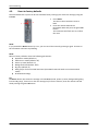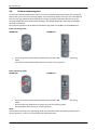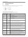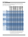
1
OccuSwitch DALI
User Manual
3222 636 49461
July 2011
Introduction to the OccuSwitch DALI
This manual covers the following products:
LRM2070, LRM2071, LRM2072
LRM2080, LRM2081, LRM2082
LRM2090, LRM2091
LCU2070, LRH2070, LCC2070, LCC2080
It does NOT cover the LRM2095
only partly, BMS integration not included
Version 1.37
July 2011
Publication number 3222 636 49461
2
Table of contents
Table of contents
1.
INTRODUCTION TO THE OCCUSWITCH DALI .......................................................................................................... 5
2.
OPERATING PRINCIPLE .......................................................................................................................................... 6
2.1.
OCCUSWITCH DALI VERSIONS ..................................................................................................................................... 6
2.1.1.
OccuSwitch DALI Basic ................................................................................................................................. 9
2.1.2.
OccuSwitch DALI Advanced ....................................................................................................................... 10
2.1.3.
OccuSwitch DALI BMS ................................................................................................................................ 11
2.1.4.
Extension movement sensor ...................................................................................................................... 12
2.2.
LUMINAIRE CONTROL ............................................................................................................................................... 13
2.2.1.
Group assignments .................................................................................................................................... 13
AUTOMATIC CONTROL ........................................................................................................................................................... 14
2.2.2.
Occupancy ................................................................................................................................................. 14
2.2.3.
Daylight regulation .................................................................................................................................... 14
2.3.
LOCAL MANUAL CONTROL ......................................................................................................................................... 16
2.3.1.
Manual control channels ........................................................................................................................... 16
2.3.2.
Manual control with the IRT8050 .............................................................................................................. 17
2.3.3.
Manual control with the IRT8010 .............................................................................................................. 17
2.3.4.
Infrared manual control groups ................................................................................................................. 17
2.3.5.
Manual control with Enocean® switches. .................................................................................................. 18
2.3.6.
Manual control with standard switches and the LCU2070 ........................................................................ 19
2.3.7.
Presets ....................................................................................................................................................... 20
2.3.8.
Manual control of multiple OccuSwitch DALI ............................................................................................ 20
3.
APPLICATION DESIGN .......................................................................................................................................... 22
3.1.1.
Luminaire output ....................................................................................................................................... 22
3.1.2.
Use area ..................................................................................................................................................... 22
3.2.
SELECTING THE OCCUSWITCH DALI TYPE ..................................................................................................................... 25
3.2.1.
OccuSwitch DALI or extension sensor ........................................................................................................ 25
3.2.2.
Type of OccuSwitch DALI ........................................................................................................................... 26
3.3.
SELECTING THE OCCUSWITCH DALI MODE ................................................................................................................... 26
3.3.1.
Parallel operation and open plan mode (mode 9) LRM208x only ............................................................. 28
4.
COMMISSIONING ................................................................................................................................................ 31
4.1.
CONFIGURE CONTROLS AND SWITCHES ........................................................................................................................ 32
4.1.1.
IRT8010 ...................................................................................................................................................... 32
4.1.2.
IRT8050 ...................................................................................................................................................... 33
4.1.3.
EnOcean® switches .................................................................................................................................... 34
4.2.
CONFIGURE THE OCCUSWITCH DALI .......................................................................................................................... 35
4.2.1.
Checks ........................................................................................................................................................ 35
4.2.2.
Motion detect timer................................................................................................................................... 35
4.2.3.
Assigning luminaires to DALI groups ......................................................................................................... 35
4.2.4.
Calibration of the required light level ........................................................................................................ 36
4.2.5.
100 hour burn-in mode .............................................................................................................................. 38
4.2.6.
Request application mode ......................................................................................................................... 38
4.2.7.
Mass programming ................................................................................................................................... 39
4.2.8.
Set application mode ................................................................................................................................. 39
4.2.9.
Background level ....................................................................................................................................... 39
4.2.10.
Power-up state .......................................................................................................................................... 40
4.2.11.
Infrared group address .............................................................................................................................. 40
4.3.
RESET TO FACTORY DEFAULTS .................................................................................................................................... 41
4.4.
PERFORM WITNESSING TEST ...................................................................................................................................... 42
3
Table of contents
5.
TECHNICAL SPECIFICATIONS ................................................................................................................................ 43
5.1.
5.2.
LED FEEDBACK ....................................................................................................................................................... 43
SETTINGS OVERVIEW ................................................................................................................................................ 44
6.
FAQ ..................................................................................................................................................................... 46
7.
DATASHEET ......................................................................................................................................................... 47
4
Introduction to the OccuSwitch DALI
1.
Introduction to the OccuSwitch DALI
OccuSwitch DALI is a lighting dimming system for offices, schools, meeting rooms, storage rooms, restrooms
and other indoor locations. The OccuSwitch DALI dimming system is a combination of daylight depending
regulation, occupancy control and manual control. The system automatically turns the lighting in a room on
and off based on occupancy. When enough daylight (natural light) enters the room, the system dims the
luminaires (artificial lights).
OccuSwitch DALI is a combined sensor and controller. It has three main functional parts: a light sensor for
daylight depending regulation, a movement detector for occupancy control and an infrared receiver for
remote control.
The OccuSwitch DALI has options for local override, parallel operation and network links to Building
Management Systems (BMS).
The specific OccuSwitch DALI BMS and DL (LRM209x) functions are not discussed in this manual.
Table 1: Main technical features
Feature
Description
Number of ballasts per OccuSwitch DALI
Maximum of 2 extension sensors and 15 ballasts per
OccuSwitch DALI.
Parallel linking
Maximum of 22 OccuSwitch DALI (Advanced) linked in
parallel.
Detection area
Office area of 20-25 m2, or
a classroom of around 48 m2.
Detection area optionally extended with an extension
sensor.
Mounting
Optimized for recessed ceiling mounting and for
mounting heights between 2.5 and 3.5 meter.
Application modes
10 available modes to suit different locations.
EnOcean® technology
Optional interface that allows using EnOcean® switches
from third parties. Both 1 and 2 channel switches can be
used.
Building Management Systems (BMS)
Up to 64 OccuSwitch DALI LRM2090 devices can be linked
to standard DALI interfaces.
5
Operating principle
2.
Operating principle
2.1.
OccuSwitch DALI versions
The following products are available for the OccuSwitch DALI lighting dimming system:
Table 2: OccuSwitch DALI products
OccuSwitch DALI product
LRM2070 OccuSwitch DALI
Basic
LRM2071 OccuSwitch DALI
Basic with EnOcean
LRM2072 OSD basic NB
LRM2080 OccuSwitch DALI
Advanced
LRM2081 OccuSwitch DALI
Advanced with EnOcean
LRM2082 OSD advanced NB
LRM2090 OccuSwitch DALI
BMS
LRM2091 OccuSwitch DALI
BMS with EnOcean
LRM2092 OSD BMS NB
LRM2095 OSD DL
6
Description
Stand alone system with 2 DALI output
connectors for window and corridor
installation.
As LRM2070 but with interface for 1- or 2channel EnOcean switches.
Exactly like LRM2070 but without Philips logo
on the front plate
Stand alone system with 2 DALI output
connectors. One connector is programmable for
the luminaires. The other connector forms a
parallel link to up to 22 different OccuSwitch
DALI systems.
As LRM2080 but with interface for 1- or 2channel EnOcean switches.
Exactly like LRM2080 but without Philips logo
on the front plate
Stand alone system with 1 DALI input and DALI
output connector. One connector is
programmable for the luminaires. The other
connector contains a standard DALI interface
for connecting to a BMS system, not specifically
covered in this manual.
As LRM2090 but with interface for 1- or 2channel EnOcean switches, not specifically
covered in this manual.
Exactly like LRM2090 but without Philips logo
on the front plate, not specifically covered in
this manual.
Dynamic Lighting version, not specifically
covered in this manual.
Operating principle
The following accessories are available for the OccuSwitch DALI lighting dimming system:
Table 3: OccuSwitch DALI accessories
OccuSwitch DALI accessory
LRM8118 extension movement sensor
LCC2070 standard Wieland cable
LCC2080 standard Wieland cable
Description
The LRM8118 can extend the
movement detection area of
OccuSwitch DALI: it has the same
detection area size as the OccuSwitch
DALI. The sensor is connected to the
same DALI channel as the luminaires,
and does not require mains power.
Cable for OccuSwitch DALI Basic
systems LRM2070 and LRM2071.
LRH2070 surface mounted box
Cable for OccuSwitch DALI Advanced
systems LRM2080 / LRM2081 and
OccuSwitch DALI BMS systems
LRM2090 / LRM2091.
Box for mounting the OccuSwitch DALI
system (all types) onto the ceiling.
The box is equipped with mounting
holes for standard BESA boxes and
socket plates.
IRT8097 (OmniProg Easy) simple
commissioning tool
Tool capable of limited commissioning.
Batteries included.
IRT8099 (OmniProg) advanced mode
selection / commissioning tool
Tool capable of full commissioning.
Batteries included.
IRT8010 two-key remote control
Infrared single-channel switch for the
OccuSwitch DALI system.
A wall holder is separately available.
Batteries included.
Holder for remote control IRT8010.
LRH8010 wall holder
IRT8050 two-key remote control
LCU2070 OSD PBU
7
Wall-mounted or tabletop infrared
control of the OccuSwitch DALI system.
Can be configured for luminaire group
control.
Batteries included.
Push button interface for OSD
Operating principle
LCU2071 OSD PBU
Push button interface for OSD
(LRM2095 only)
UID8510
IR remote control (1 or 2 channels).
Batteries are included
8
Operating principle
2.1.1.
OccuSwitch DALI Basic
Figure 1: Two cell offices with OccuSwitch DALI Basic installations
The OccuSwitch DALI Basic is a module with 2 DALI output connectors, for window and corridor installation.
The OccuSwitch DALI Basic is ideal for separate cell offices. Depending on commissioning and the number of
output connectors in use, the OccuSwitch DALI Basic functions as follows:
Table 4: Connectors in OccuSwitch DALI Basic
Number of connectors in use
Uncommissioned system
Commissioned system
1 DALI output connector (DA)
used
Other connector (X) left open
The system regulates all
connected luminaires identically,
according to the output
connector used. When the
window-row connector (DA) is
used, daylight regulation can
cause the amount of light from
the corridor luminaires to be
insufficient.
Up to four output groups
(window row, corridor row, plus
two additional groups) can be set.
This allows setting correct light
levels for all luminaire groups.
The groups do function
independently of their physical
connection location.
For commissioning, see Chapter 4.
2 DALI output connectors used
(DA and X)
The system regulates window
(DA) and corridor (X) luminaires
as separate rows. The corridor
row has a set offset from the
window row.
Example
Figure 1 shows an example layout of two simple cell offices: one small and one large. Each office part has its
own OccuSwitch DALI Basic and two rows of luminaires (a window row and a corridor row). There are no
devices in the office to manually override the automatic lighting control.
In this example, the OccuSwitch DALI Basics in the three office parts (A, B and C) are completely independent
of each other: each has an independent occupancy control and daylight regulation.
9
Operating principle
2.1.2.
OccuSwitch DALI Advanced
Figure 2: Two grids in one office linked with an OccuSwitch DALI Advanced installation
The OccuSwitch DALI Advanced is a module that allows covering larger areas such as open plan offices. Up to
22 OccuSwitch DALI Advanced modules can be connected in parallel to create lighting zones in an open
office. These lighting zones can be used, for example, so that the local lights in one area are switched on at
occupancy and the lights of the surrounding areas are automatically set to the background lighting level.
Table 5: Connectors in OccuSwitch DALI Advanced
Output connectors
Uncommissioned system
Commissioned system
DALI Output connector “DA”
The system regulates all luminaire
rows identically. The system sees
all luminaires as window row.
Daylight regulation can cause the
amount of light from the corridor
luminaires to be insufficient.
Up to four output groups
(window row, corridor row, plus
two additional groups) can be set.
This allows setting correct light
levels for all luminaire groups.
For commissioning, see Chapter 4.
Parallel link connector “X”
By default the OccuSwitch DALI
Advanced is set to local
occupancy (Mode 1). Once one
OccuSwitch DALI detects
occupancy, all OccuSwitch DALI
devices on the same parallel link
turn their lights on.
It is possible to set other
OccuSwitch DALI devices using
the same parallel link to go to
background level when one
OccuSwitch DALI is occupied
(Mode 9).
Example
Figure 2 shows an example layout of a two simple cell offices: one small and one large. Each office part has
its own OccuSwitch DALI Advanced and two rows of luminaires (a window row and a corridor row). The two
OccuSwitch DALI Advanced in the large office (B and C) are connected via parallel link, so they can share their
occupancy status with each other. This means that when someone enters the office in side B, the lights in
side B are switched on and side C is signaled. Depending on configuration, the lights in office C are then
either switched on or switched to the background level.
10
Operating principle
2.1.3.
OccuSwitch DALI BMS
Figure 3: Two cell offices linked to a BMS system
The OccuSwitch DALI BMS is a module that allows connecting a maximum of 64 OccuSwitch DALI devices to a
DALI interface, for example of a BMS system. Each OccuSwitch DALI can be assigned to a maximum of 16
groups.
The BMS system can override the local OccuSwitch DALI control. This allows, for example, to switch all lights
on when specific alarms occur or to keep all lights off during the night. The BMS system can also retrieve
status information from each OccuSwitch DALI device.
Table 6: Connectors in OccuSwitch DALI BMS
Connectors
Uncommissioned system
Commissioned system
DALI output connector
The system regulates all luminaire
rows identically. The system sees
all luminaires as window row.
Daylight regulation can cause the
amount of light from the corridor
luminaires to be insufficient.
Up to four output groups can be
set. This allows setting correct
light levels for the luminaire
groups.
For commissioning, see Chapter 4.
DALI input connector
Complete standard DALI interface for connecting to any DALI system.
For commissioning, see Chapter 4.
Example
Figure 3 shows an example layout of two cell offices: one small and one large. Each office part has its own
OccuSwitch DALI BMS and two rows of luminaires (a window row and a corridor row). The OccuSwitch DALI
devices are not directly linked to each other, but are connected to a BMS system.
Both OccuSwitch DALI BMS systems control the connected lights automatically. The BMS system is used to
monitor the system and to override the local settings in special situations.
11
Operating principle
2.1.4.
Extension movement sensor
Figure 4: OccuSwitch DALI with an extension movement sensor
The extension sensor (LRM8118) allows enlarging the movement detection area of any OccuSwitch DALI. The
sensor is connected to the same DALI line as the luminaires. When the extension movement sensor detects
occupancy it sends a trigger to the OccuSwitch DALI. The OccuSwitch DALI reacts on this trigger as if it
detected the movement with its built-in movement detection sensor. This means that the luminaires are
controlled on movement detection in both the main and the extension area.
The extension movement sensor is ideal for areas, such as classrooms, that are slightly larger or differently
shaped than the standard movement detection area of the OccuSwitch DALI. Up to two extension sensors
may be connected to one OccuSwitch DALI.
NOTE
The extension movement sensor only extends the movement detection range of the OccuSwitch DALI. In
some cases it is better to use multiple OccuSwitch DALI, instead of extending the detection range of one. For
criteria on this, see Section 3.2.1.
12
Operating principle
2.2.
Luminaire control
2.2.1.
Group assignments
The OccuSwitch DALI can address four different groups of luminaires, by using four DALI groups. The
following table shows the groups in which the luminaires can be used.
Table 7: Infrared channels available
DALI slave group
Default function
Description of default function
DALI group 1
Window luminaires
Auto on/auto off, automatic light level regulation for
window side.
DALI group 2
Corridor luminaires
Auto on/auto off, automatic light level regulation for
corridor side.
DALI group 3
Additional presence
luminaires
Auto on/auto off, no automatic light level regulation.
DALI group 4
Additional absence
luminaires
Manual on/auto off, no automatic light level regulation.
The following figure shows an application where all groups are in use:
For assigning luminaires to these DALI groups, see Section 4.2.3.
The window and corridor side speak for itself, but the additional groups are not so obvious.
Additional presence (group 3) is mainly used for luminaires in the area that do not have a window or corridor
function nor daylight regulation and might be changed separately from the main lights. Typical examples are
wall washers, task lighting, etc.
Additional absence (group 4) is used for additional luminaires with a specific function. The most common
function is board lighting (for schools and meeting rooms).
The OSD will accept luminaires with ballasts that have already a DALI group address programmed. Please be
aware that you need to program all ballast during the DALI commissioning, it is not possible to assign a single
luminaire and leave the rest as it is.
13
Operating principle
Automatic control
This section shows how the automatic control of the OccuSwitch DALI is based on occupancy and daylight
regulation.
2.2.2.
Occupancy
The OccuSwitch DALI can automatically switch lights ON when the area is occupied and switched them OFF
when the area is vacated. After the area is left unoccupied for a set time period, the lights will either switch
OFF automatically or first dim to a background level for a set time period.
On some occasions when there is very little movement, the standard delay time of OccuSwitch DALI might be
too short. If movement is detected during the turn-off fade (this takes 10 seconds) the lights will return to
their “ON” value and the delay time is automatically increased by 10 minutes (Smart Timer).
Movement sensor
The movement sensor is a PIR (Passive Infra Red) sensor that detects occupancy in an area. When installed in
a typical office ceiling at 3-metre height (between 2.5 and 3.5 meter), it is sensitive for small movements
within a range of 4 by 5 meters and to large movements within a range of 8 by 6 meters.
The PIR sensor reacts on movement by means of a temperature difference such as the human body
temperature versus its surrounding temperature. A car that just starts its engine is not seen by the PIR, nor
does it see people sitting within the car or a forklift truck. Therefore it is recommended not to use the
OccuSwitch DALI system in outdoor, parking or industrial applications.
The movement detection range can be extended with an extension movement sensor, which has the same
viewing specifications as the standard sensor.
NOTE
It is possible to limit the detection area of the movement sensor with a retractable shield.
2.2.3.
Daylight regulation
The OccuSwitch DALI has an automatic daylight regulation with a dynamic offset for the window and corridor
rows. Daylight regulation helps to keep a constant light level at all situations.
Daylight sensor
The daylight sensor reads the actual average luminance. The intensity of the luminance depends on the
amount of artificial and / or natural light in the room as well as on how well this light is reflected towards the
ceiling. The light reflection depends highly on the colors and materials chosen to furnish the office.
For more information on this sensor, see section “Light sensing” on page 24.
For calibrating the daylight sensor, see Section 4.2.4.
NOTE
In case problems occur, it is possible to limit the detection area of the daylight sensor with an
additional shield. Please contact your local Philips representative.
14
Operating principle
Dynamic offset control for window / corridor
Since the window area receives more daylight than the corridor area, window and corridor luminaires are
controlled separately. Depending on the amount of daylight entering the room, the output of both window
and corridor luminaire rows are dimmed to a minimum level with a difference of 30% between the window
and corridor side.
When both window and corridor rows have been dimmed to the minimum level for more than 15 minutes,
the window row will be turned off to ensure maximum energy saving. The corridor side, however, will by
default only dim to the minimum level, hence indicating to the user that the lighting is operational.
NOTE: This default can be overridden, in order to turn the corridor row off as well. For this special case,
please contact your local Philips representative for details.
In the daylight override function, the lights will switch on when someone enters the room even when there is
sufficient natural daylight available.
Figure 5 shows the dynamic behavior (offset) of the window and corridor row luminaires.
Figure 5: Dynamic offset between window and corridor
15
Operating principle
2.3.
Local manual control
The OccuSwitch DALI can be manually controlled using IR remotes, Enocean® and (with the LCU2070 PBU)
normal pushbutton switches. Manual control is required for switching on the system in semi-automatic
(manual on / automatic off) applications and for manually overriding the OccuSwitch DALI automatic control
functions.
CAUTION
Take into consideration that manual control will always stop the daylight regulation.
The OccuSwitch DALI will start regulating again according when:
Occupancy after the area was unoccupied (the lights switch off).
Give a general switch on command (shortly press channel 1 on the remote or switch)
Select Preset 1 on the OccuSwitch DALI (see section 2.3.7 Presets)
2.3.1.
Manual control channels
The manual control can be done on 5 different channels, as shown in the following table:
Table 8: Manual control channels available
Control channel
DALI slave group
Description
Channel 1 (Default)
DALI groups 1, 2 and 3
Window, corridor and additional presence luminaires.
When manually setting the light level, the corridor and
additional presence luminaires will follow the window
channel with an offset. Daylight override may cause
window luminaires to stay off.
Channel 2
DALI group 1
Window luminaires
Channel 3
DALI group 2
Corridor luminaires
Channel 4
DALI group 3
Extra auto on
Channel 5
DALI group 4
Additional absence luminaires
By default the remote controls are set to only channel 1, simultaneously controlling window, corridor and
additional presence luminaires. Only the IRT8050 can be configured to use other channels. For setting the
infrared channels, see the datasheet of the remote.
16
Operating principle
2.3.2.
Manual control with the IRT8050
The IRT8050 can be used in many configurations. The table below shows the most common configurations.
The default settings of the IRT8050 are listed on the first line. For more information please check the
datasheet of this device.
Table 9: Manual control functions with the IRT8050
Normal application function Switch
Dim
General on/off dim
Window side
Corridor side
Additional lighting
Board lighting
General on/off
General lighting + window control
Window/corridor control
General on/off/dim + board lighting
OSD Channel 8050 DIP
1 2 3 4 45678
IRT 8050 function
Ch 1 Off / Down
Ch 2 Off / Down
Ch 3 Off / Down
Ch 4 Off / Down
Ch 5 Off / Down
All Off
Ch 1 On & Ch 1 Off
Ch 2 On & Ch 2 Off
Ch 5 On & Ch 5 Off
Ch 1 On / Up
Ch 2 On / Up
Ch 3 On / Up
Ch 4 On / Up
Ch 5 On / Up
Preset 1
Ch 2 On & Ch 2 Off
Ch 3 On & Ch 3 Off
Ch 1 On & Ch 1 Off
The combined function off/dim down and on/dim up can be operated with a short press (switch on or off) or
by a long press, enabling the dimming function.
2.3.3.
Manual control with the IRT8010
The IRT8010 is a single channel remote control.
Please note that the IRT8010 cannot address the second additional channel (DALI group 4).
The IRT8010 is a two-key remote control, suitable for switching on / off and dimming up / down single
lighting control circuits (one channel control). It enables manual override of the OccuSwitch DALI automatic
control system. The control can only handle IR channel 1, so in combination with the OSD general on/off and
dim commands can be send. Suitable for schools / classrooms and meeting rooms. When place in the LRH810
holder it can also function as ‘wall switch’.
Note you cannot change the function of this device, only the IR group it belongs to.
The infrared group address can be set with a rotary switch within the unit itself.
Use (section 2.3.1)
Manual control channel 1
(window, corridor and additional
presence)
2.3.4.
Error! Reference source not
ound. (Error! Reference source
not found.)
Short press: lights off
Long press: lights dim down
Error! Reference source not
ound. (Error! Reference source
not found.)
Short press: lights on
Long press: lights dim up
Infrared manual control groups
The OccuSwitch DALI contains an infrared receiver that enables the manual (remote) control of the system.
For the maximum distances of the controls to the receiver, see the datasheet of the controls.
Infrared group addressing makes it possible to control individual light groups in open plan offices without
affecting the light level of neighbors. The OccuSwitch DALI can be set to one of seven available groups (group
A, B, C, D, E, F or G).
17
Operating principle
Figure 6: Infrared groups
The default infrared group for the OccuSwitch DALI and the remote controls is group A. The OccuSwitch DALI
and the remote control must always operate in the same group.
Setting the infrared group of the OccuSwitch DALI is done with the OmniProg, see Section 4.2.11.
2.3.5.
Manual control with Enocean® switches.
REMARK: This section only applies to the EnOcean® enabled versions of the OccuSwitch DALI (LRM2071,
LRM2081 and LRM2091).
It is not possible to indicate the maximum distance between an Enocean® switch and the OSD, since
switches are not supplied with the OSD. In general (without any guarantee) a distance of 10...15 meter can
be bridged. Walls, especially with reinforced concrete will strongly shorten this range.
EnOcean® technology provides a wireless and battery-less mechanism to transmit rocker commands to one
or more receivers. In the OccuSwitch DALI this technology enables manual override of the automatic control
system. The switches are suitable for 1-channel or 2-channel semi-automatic applications (schools /
classrooms and meeting rooms with light scene options).
The OccuSwitch DALI supports two types of EnOcean controls. The single rocker switch is suitable for
switching and dimming single lighting control circuits (one channel control). The dual rocker switch is suitable
for switching and dimming dual lighting control circuits (two channel control).
For binding an EnOcean® switch to the OccuSwitch DALI, see Section 4.1.3.
Single rocker
Manual control channel 1:
window, corridor and
additional presence 1
Short press: lights off
Long press: lights dim down
Short press: lights on
Long press: lights dim up
“O” side
“I” side
1
For the definition of channels, see section 2.3.1.
18
Operating principle
Dual rocker
Use mode 2
Mode 1
Mode 2
“O” side
“I” side
2.3.6.
Left (A)
Channel 1: window, corridor
and additional presence
Channel 2: window
Right (B)
Channel 5: additional absence
Short press: lights off
Long press: lights dim down
Short press: lights on
Long press: lights dim up
Short press: lights off
Long press: lights dim down
Short press: lights on
Long press: lights dim up
Channel 3: corridor
Manual control with standard switches and the LCU2070
The LCU2070 push button interface makes it possible to connect any type of push button to the OSD system.
The connection is simple, connect the interface (with the black wires) to the DALI line, and connect 1 till 4
switches to the unit. Each switch has a specific function. This function is fixed.
Note; extra auto-on = additional presence luminaires &
extra manual-on = additional absence luminaires
The switches work with a Touch & Dim function that
also can be found in many ballasts. The function is
show on the right hand side.
2
For binding a switch to one of these modes, see section 4.1.3.
19
Operating principle
2.3.7.
Presets (basic & advanced versions)
Presets are used to recall pre-programmed light scenes. Selecting presets is only possible with the IRT8050 or
IRT8080 transmitters. There are 4 presets available, as shown in the following table:
Preset 1
Preset 2
Preset 3
Preset 4
Window row
Automatic
100%
50%
10%
Corridor row
Automatic
100%
50%
10%
Extra Auto-on row
100%
100%
50%
10%
Extra Manual-on row
Unchanged
100%
50%
10%
Preset 1 is fully automated mode of the OccuSwitch DALI. When selecting this mode, the automatic daylight
regulation starts working, based on the calibrated maximum light level.
Preset 2 to 4 use the predefined light level as shown in the table. When the OccuSwitch DALI is set to one of
these presets, all luminaires react in the same way. For example, setting the OccuSwitch DALI to preset 3
causes all luminaires go to 50% of the maximum light level.
NOTE: In the OccuSwitch DALI Basic and OccuSwitch DALI Advanced systems the values for the presets
cannot be changed.
Selection of preset 2,3 or 4 will stop daylight depending regulation. All manual control will restart the
occupancy timer.
2.3.8.
Presets (BMS version)
Presets (selected by the user via a remote control (IRT8050 or IRT8080) and scenes (selected and
programmed via de (BMS) DALI interface) overlap each other.
Preset 1 and Scene 1 are the same, as are 2,3 and 4. This means that a scene 2 command from the DALI
interface will result in the same action as selecting preset 2 on a remote control.
Presets 2,3 and 4 cannot be changed via the IR interface (e.g. with a IRT8050), but CAN be changed via the
DALI interface (select a value and load it into scene 2,3 or 4).
Preset 1 and scene 1 cannot be changed, this is the automated mode. It is possible to program scene 1 and if
the scene setting is read back the original value will be reported. However the OSD will not use this value
when recalled and go into automated mode instead.
The default values of the scenes and preset are shown in the table in the previous paragraph. Both preset
and scene commands will reset the occupancy timer.
NOTE: Repeat the scene command if the lights need to switched on, even without somebody being
present. The repeat time should be shorter than the selected occupancy timer.
2.3.9.
Manual control of multiple OccuSwitch DALI
Sometimes it is required that two OSD units are manually controlled by one user interface.
Using IR remote controls
In general the IR remote controls will have a reach of 5...7 meter. So you can control a neighboring OSD as
well, provided they use the same IR group.
Using Enocean® switches
You can bind switches to several OSD units, without any problems, to control neighboring OSD as well.
20
Operating principle
Using standard switches and the Push Button Interface
You can connect a single switch to multiple push buttons units.
You need a LCU2070 PBU per OSD unit you want to control.
The schematic on the right shows the general idea.
21
Application design
3.
Application design
To design the OccuSwitch DALI in any application, the designer must:
1. Select the number of control areas to use and define the position of the sensors
2. Choose the OccuSwitch DALI type(s) to use: stand-alone, linked or controlled from a central building
management system. Option to use with EnOcean.
3. Choose or design the mode that each OccuSwitch DALI needs to work in.
Each of these steps is explained in more detail in the subsections of this chapter.
The number of OccuSwitch DALI to be used in an application on one hand depends on the area that needs to
be covered by the sensors and on the other hand on the number of output luminaires to control.
3.1.1.
Luminaire output
The DALI output of the OccuSwitch DALI can be loaded with a maximum of 15 DALI ballasts or extension
sensors.
As each luminaire is usually controlled by one ballast, the maximum area to be controlled by one OccuSwitch
DALI is restricted to 15 ballasts. This number is reduced when using one or more extension sensors: each
extension sensor counts for one DALI ballast. The maximum number of extension sensors per OccuSwitch
DALI is 2: in this case the 13 luminaire ballasts can be controlled.
If the lighting requirements for an area require more than 15 luminaires, the area should be split in to sub
areas. Each of these sub areas can then be controlled by a separate OccuSwitch DALI.
3.1.2.
Use area
The OSD is detecting movement for occupancy and measuring light levels for daylight depending control
The detection area of the OccuSwitch DALI is defined by the detection limits of its movement detection
sensor and its light sensor. To ensure a reliable working, the number of OccuSwitch DALI in the application
must be defined with these detection fields in mind.
The detection area of the OccuSwitch DALI and the extension sensor depends on the height of the ceiling
where it is installed. In this manual, an installation height between 2.5 and 3.5 meter is assumed.
NOTE: if you want to use the OccuSwitch DALI in an application with a ceiling height of less than 2.5
meters, the detection area is significantly smaller. Please contact your local Philips representative for the
exact dimensions.
NOTE: use of the OccuSwitch DALI in an application with a ceiling height of more than 4 meters may cause
in unreliable movement detection, and is therefore advised against.
22
Application design
Movement detection
At a ceiling height of 3 meter, the maximum movement detection area of both the OccuSwitch DALI and the
extension sensor is 6 by 8 meter. However the useful area of the sensor is limited to 20 m².
Figure 7: Movement detection range and
design of OccuSwitch DALI
Figure 8: Shielding the movement detection range
When a part of the sensor’s viewing area should not be used for movement detection, the area of movement
detection can be partially reduced by the retractable view shield (see
Figure 8).
For applications where little movement is made, like an office application, the number of movement
detection sensors must be calculated by dividing the total area of the room in parts of 4 by 5 meter. In the
center of each of these parts, one OccuSwitch DALI or extension sensor must be placed. For choosing
whether to use multiple OccuSwitch DALI or to use one OccuSwitch DALI with extension sensors, see Section
3.2 “Selecting the OccuSwitch DALI type” on page 25.
For applications where larger movements are made, like a corridor or a central hall, the outer detection area
can also be used, so the total area can be divided in parts of 6 by 8 meters.
NOTE: To ensure reliable movement detection, all of the applicable space must be covered by the
detection area of either an OccuSwitch DALI or an extension sensor. Therefore, for calculating the rough
number of OccuSwitch DALI or extension sensors, the resulting number of dividing the total area by the
sensor detection area must be rounded up towards the next whole number.
Tip: When placing the designed position of the OccuSwitch DALI or extension sensor in an installation
drawing, note the direction of the detection area. The OccuSwitch DALI or extension sensor must be placed
according to this direction. To do this alignment, the “Philips” word mark and the sensor line-up can be used.
23
Application design
Light sensing
The OccuSwitch should be placed in such a way that the sensor does not “see” any outside lights, for
instance from windowsills, parked cars, etc. etc.
For this the sensor should be placed as shown in figure 9.
Figure 9: Light detection range and position
24
Application design
3.2.
Selecting the OccuSwitch DALI type
When the detection areas are known, you should define which sensor to use for each area: an OccuSwitch
DALI Basic, OccuSwitch DALI Advanced, OccuSwitch DALI BMS, or an extension sensor. This decision should
be based on the grouping of the detection areas, and the amount of communication needed between these
groups. For all OccuSwitch DALI sensors also choose if you want to use this OccuSwitch DALI with EnOcean
switches.
3.2.1.
OccuSwitch DALI or extension sensor
First step is to select for each detection area between using an OccuSwitch DALI or an extension sensor. To
this purpose you must define application areas, where all the luminaires must be dimmed as a group. An
application area may contain one or more detection areas, but can be controlled by one single OccuSwitch
DALI. If the application area contains more than one detection field, the extra fields will be monitored by
extension sensors connected to the same OccuSwitch DALI. Take care however that the total number of
luminaires and extension sensors per OccuSwitch DALI does not exceed the maximum allowed load.
In the simplest case, a room is so small that it is totally covered by one detection
area. In this case there is only one application area, which consists of only one
detection area. This application area needs one OccuSwitch DALI without any
extension sensors.
In a larger room, multiple detection or control areas are needed. These detection areas must be grouped into
application areas:
If the light levels all over the room must be controlled as a whole, the
detection areas in the room are grouped as only one application area,
which can be controlled by one OccuSwitch DALI. The additional
detection area is covered by using an extension sensor.
If the luminaires in the different detection areas may be dimmed
separately, each detection area can be defined as a application area.
For each application area, one OccuSwitch DALI is used.
If communication between OccuSwitch DALI is used (see next section), it is still possible and fairly easy to
make separate application areas work as one regarding movement detection. Splitting an application area is
much harder, as it needs replacement of an extension sensor by an OccuSwitch DALI, and a split in the DALI
connection. It is therefore recommended to carefully choose between an extension sensor and an
OccuSwitch DALI.
25
Application design
3.2.2.
Type of OccuSwitch DALI
After defining for each area whether an OccuSwitch DALI or an extension sensor is used, you can select for
each OccuSwitch DALI which model to use, depending on the need for communication with any neighboring
application areas and/or a building automation system:
If the OccuSwitch DALI Basic is used, no communication will take place
with neighboring application areas or a building automation system. It
will operate stand-alone, dimming and switching the light according to
its own measurements and that of any connected extension sensors.
If the OccuSwitch DALI Advanced is used, OccuSwitch DALI can be
connected to each other via a “Parallel link”. Each OccuSwitch DALI
regulates the light level according to its own measurements, but in
addition it will use the parallel link connection to report and react on
movement detection. If one of the connected OccuSwitch DALI detects
movement, it reports this on the parallel link. Each of the other
OccuSwitch DALI on the link are set to either:
switch the local luminaires as if movement was detected locally,
or
switch the local luminaires on, at a pre-programmed background
lighting level.
If the OccuSwitch DALI BMS is used, the OccuSwitch DALI will
communicate with a DALI-capable building management system
NOTE: In a DALI network it is not possible for OccuSwitch DALI devices
to exchange data directly with each other. All communication is going
via the DALI master.
As the last step for selecting the OccuSwitch DALI type, it should be defined if the OccuSwitch DALI must be
equipped with EnOcean capability. The EnOcean capability is needed if the OccuSwitch DALI must be locally
controlled with EnOcean switches.
3.3.
Selecting the OccuSwitch DALI mode
Once the placement of the OccuSwitch DALI(es) is selected (as explained in Section 3.2), it has to be specified
how the OccuSwitch DALI must react on its movement detection, light sensor, and optional parallel link. The
OccuSwitch DALI has 10 application modes (9 predefined and one customizable) that define how the
connected luminaires are controlled.
Table 10 (on next page) shows the application modes and their parameters. For an explanation of the
parameters in this table, see below:
Auto switch-ON: the lights will automatically switch on when someone enters the area.
26
Application design
Auto switch-OFF: the lights will automatically switch off when the area is vacated (and no parallel
link activity has taken place) for the duration given with the potentiometer.
Smart timer: when the lights automatically switch off, and a movement is detected during this fade
down, the OccuSwitch DALI temporarily extends the movement detection period (as given with the
potentiometer). The smart timer value shown in the table defines with how many minutes the
movement detection period will be extended.
Background period: the OccuSwitch DALI will keep its luminaires on background level for this many
minutes, before switching the luminaires off. See also Figure 10 below.
Activity on parallel link acts as: defines what action the OccuSwitch DALI will take an event occurs on
its parallel link while its luminaires are off. Two options exist: local occupancy means that the
OccuSwitch DALI will act as if local occupancy is detected; background lighting means that the
OccuSwitch DALI will switch all its luminaires on at the background level.
Daylight dependent regulation: luminaires will be dimmed depending on the measured light level.
Daylight switching on window/corridor side: when sufficient daylight is available the luminaires (of
the given side) will be switched off.
Daylight override: when the OccuSwitch DALI detects movement and sufficient daylight is available,
the luminaires for which daylight switching is enabled will not switch on.
Figure 10: Movement detection phases
Selecting a mode for an OccuSwitch DALI can be done in two ways:
For an easy selection, look up the mode based on the application that the OccuSwitch DALI is used in.
To select the mode, find the application type in the table.
For example: when using an OccuSwitch DALI Advanced in an open plan office, with parallel link
connected, the OccuSwitch DALI can be placed in mode 9: “Open plan office with parallel link”.
For a more advanced selection, select the mode based on the parameters.
If the required set of parameters is not listed as one of the modes 1-9, you may select to use a
custom application mode, which is mode 10. For more information on using this custom mode,
please contact your supplier.
27
Application design
3.3.1.
Parallel operation and open plan mode (mode 9) LRM208x only
The LRM208x can be used in parallel mode. With this feature different (up to 22) units can be connected in
parallel as the figure below shows.
In all modes except mode 9 parallel operation means that occupancy is truly handled as parallel. In other
words if one sensor picks up occupancy, all devices will react as if their own sensor was triggered.
Parallel operation does not mean that the units act in the same way!
Only the occupancy trigger is shared. The units will switch off in different ways if timers are set in different
ways. For this the OSD has a digital potentiometer for the delay timer. If set around 15 minutes, the unit will
make the time exactly 15 minutes. So if several units are used in the same area, please set the timer at
almost the same position. When the complete area is now vacated all units will switch off (or dim to
background level) within 3 seconds.
28
Application design
Mode 9 is a special mode for this parallel operation. The OSD will
now make a difference if it detects occupancy by itself or when it
gets a message from its neighbor. In the first case lights will switch
on to nominal level, in the second case lights will switch on and
dim to background level.
Let’s look at an example. The office on the right exists of 6 office
grids with an OSD in each grid.
At starts the area is vacated for some time and all lights are off.
If somebody enters the area all lights will switch on, but at the location where
the person is present lights will be on full, in all other area’s lights will switch on
background level.
If the person moves to another sections, light sin that grid will dim up to
nominal level. In the vacated area light swill stay on at this level, until the timer
expires.
After the timer in the first grid expired lights in that section will dim to
background level.
If the person leaves the room all together lights in grids on his/her way out will
be again at nominal level. This will remain until the timers expire.
If no occupancy is detected in either of the OSD units and all timers have
expired, all lights will switch off.
29
Table 10: Mode setting overview
10
*) Only on portal luminaires (channel 1)
Smart timer
(minutes)
Activity on parallel
link acts as
Background period
(minutes)
Daylight dependent
regulation
Daylight switching
on window side
Daylight switching
on corridor side
Daylight override
6
7
8
9
Auto switch-OFF
5
Cell office
Open plan office
Class room
Cell office without movement
detection
Open plan office without
movement detection
Corridor
Toilets
Meeting room
Open plan office with parallel
link
Custom
Daylight level related
Auto switch-ON
1
2
3
4
Application
Mode
Occupancy related
Enabled
Enabled
Disabled
Disabled
Enabled
Enabled
Enabled
Disabled
10
10
10
N.A.
Local occupancy
Local occupancy
Local occupancy
N.A.
0
120
0
0
Enabled
Enabled
Enabled
Enabled
Enabled
Enabled
Enabled
Enabled
Disabled
Disabled
Enabled
Disabled
Enabled
Enabled
Disabled
Disabled
Disabled
Disabled
N.A.
N.A.
0
Enabled
Enabled
Disabled
Disabled
Enabled
Enabled
Disabled
Enabled
Enabled
Enabled
Enabled
Enabled
10
0
10
10
Local occupancy
Local occupancy
Local occupancy
Background lighting
60
15 *)
0
0
Enabled
Disabled
Enabled
Enabled
Enabled
Disabled
Enabled
Enabled
Enabled
Disabled
Disabled
Disabled
Enabled
Disabled
Disabled
Enabled
4.
Commissioning
The physical installation of the OccuSwitch DALI system is described in the installation instructions
and data sheet. These sheets are added to the printed version of this manual. Otherwise please look
at the internet pages on the OSD to get the latest version.
Once installed, the OccuSwitch DALI system is ready to be used in its default mode. However, to
assign the connected luminaires to the correct groups and to set other settings according to the
design, the OccuSwitch DALI system needs to be commissioned. The sections in this chapter show
how this is done.
The commissioning of the OccuSwitch DALI is done using the following equipment:
o Service pushbutton on the OccuSwitch DALI
o Potentiometer on the OccuSwitch DALI
o IRT8097/00 (OmniProg Easy) or IRT8099/10 (OmniProg) infrared programmer
o DALI master system (BMS version only)
The table below shows what functions can be done with each commissioning tool. Each function
(except switching on/off) is described in the subsequent sections of this chapter.
Tool
Service button
Potentiometer
OmniProg Easy
(IRT8097/00)
OmniProg
(IRT8099/10)
Programming function
Set reference light level to current level
Set reference light level by auto-calibration
Bind EnOcean switch (EnOcean enabled OccuSwitch DALI only)
Set value of delay timer
Set reference light level to current level
Check parallel link (witnessing test)
Enable 100-hour burn-in mode
Assign luminaires to group 1 (Window) or group 2 (Corridor)
Switch luminaires on/off
Set reference light level to current level
Check parallel link (witnessing test)
Assign luminaires to any group
Set light level of background lighting
Request current application mode
Set application mode
Set power-up state
Set IR group address
Reset to factory settings
Switch luminaires on/off
Note no function for 100h burn in
Commissioning
4.1.
Configure controls and switches
This section describes how to set the infrared group and channel settings for Infrared remote
controls IRT8010 and IRT8050 and how to bind an EnOcean® switch to an OccuSwitch DALI.
4.1.1.
IRT8010
In order to avoid that all lighting circuits in one room are switched unintentionally, the transmitters
present in one room and their respective receivers can be given an individual infrared group
address.
The group address of the transmitter must match the group address of the OccuSwitch DALI. The
group address of the transmitter can be changed by using the rotary switch in the battery
compartment, see Figure 11.
Figure 11: IRT8010 settings
32
Commissioning
4.1.2.
IRT8050
In order to avoid that all lighting circuits in one room are switched unintentionally, the transmitters
present in one room and their respective receivers can be given a different infrared group address.
The group address of the transmitter must match the group address of the OccuSwitch DALI. The
group address of the transmitter can be changed by dipswitches, see Figure 12.
Figure 12: IRT8050 settings
33
Commissioning
4.1.3.
EnOcean® switches
This section describes how to bind a single or a dual rocker EnOcean® switch to the OccuSwitch
DALI.
Single rocker EnOcean® switch
1. Press the push button on the OccuSwitch DALI housing for less than 3 seconds.
The OccuSwitch DALI goes to the EnOcean Learn Mode.
2. Within 10 seconds, press the push button on the OccuSwitch DALI housing for at least 3 seconds.
For four seconds, the LEDs on the OccuSwitch DALI blink in a fast cycle of long green – short
yellow. The OccuSwitch DALI is now busy.
After this four seconds, the LED on the OccuSwitch DALI blinks this same cycle (long green – short
yellow) slower. This shows that the OccuSwitch DALI is ready to receive EnOcean commands.
3. Press both switches A and B of the dual rocker switch (either “I” or “O”).
4. The OccuSwitch DALI simultaneously flashes the window, corridor and extra auto-on rows once
to indicate that it received the command.
For four seconds, the LEDs on the OccuSwitch DALI blink in a fast cycle of long green – short
yellow. The OccuSwitch DALI is now processing the EnOcean command.
After this four seconds, the LED on the OccuSwitch DALI blinks this same cycle (long green – short
yellow) slower. This shows that the OccuSwitch DALI is ready to receive EnOcean commands.
5. To bind up to three more switches to this OccuSwitch DALI, repeat step 2-4 for every switch
within 30 seconds between each other.
6. Press the push button on the OccuSwitch DALI housing within 30 seconds after the last rocker
switch was pressed for less than 3 seconds.
The OccuSwitch DALI goes back to the normal mode and the LED indicators stop blinking.
NOTE
When the maximum supported amount of rocker switches have been bound, the OccuSwitch DALI
automatically leaves the EnOcean Learn mode and the LED will stop its visual indication.
Dual rocker EnOcean® switch
1. Press the push button on the OccuSwitch DALI housing for less than 3 seconds.
The OccuSwitch DALI goes to the EnOcean Learn Mode.
2. Within 10 seconds, press the push button on the OccuSwitch DALI housing for at least 3 seconds.
The LED on the OccuSwitch DALI blinks in a cycle of green, green, green, yellow.
3. Press one rocker of the switch that you want to bind. To bind the switch in binding mode 1
(channel 1 and 5, see section Error! Reference source not found.), press the “O” side. To bind the
witch to mode 2 (channel 2 and 3, see section Error! Reference source not found.), press the “I”
side.
4. The OccuSwitch DALI simultaneously flashes the window, corridor and extra auto-on rows once
to indicate that it received the command.
5. To bind up to three more switches to this OccuSwitch DALI, repeat step 2-4 for every switch
within 30 seconds between each other.
6. Press the push button on the OccuSwitch DALI housing within 30 seconds after the last rocker
switch was pressed for less than 3 seconds.
The OccuSwitch DALI goes back to the normal mode and the LED indicators stop blinking.
NOTE
When the maximum supported amount of rocker switches have been bound, the OccuSwitch DALI
automatically leaves the EnOcean Learn mode and the LED will stop its visual indication.
34
Commissioning
4.2.
Configure the OccuSwitch DALI
4.2.1.
Checks
Make sure that the OccuSwitch DALI system has been installed correctly, by checking the LEDs and
luminaires function (see Section xxx (Basic manual)).
4.2.2.
Motion detect timer
The motion detect timer defines the time after which the lights will be turned to the background
light level, or be turned off.
1. Turn the potentiometer to the desired value.
As shown in the figure, the potentiometer
range is not linear, but divided in a number of
possible settings.
4.2.3.
Assigning luminaires to DALI groups
IRT8097/00
IRT8099/10
1
1
2
2
1. Press DALI address to start the allocation process.
The luminaires flash indicating that the OccuSwitch DALI has received the command.
One by one all luminaires dim.
When this process stops one luminaire starts to blink.
2. Select the DALI group this luminaire should be in (Window/Corridor on IRT8097, 1...4 on
IRT8099).
Directly after sending the channel number another luminaire starts to blink.
3. Repeat step 2 for all other luminaires.
When all luminaires are assigned to a channel, all luminaires blink once, and the OccuSwitch DALI
returns to normal operation.
NOTE
At all actions, stay close to the OccuSwitch DALI and point the remote control towards the sensor.
NOTE
The procedure above can be aborted at any moment by pressing DALI address again. Aborting the
assign process resets all luminaires and/or ballasts to un-commissioned state. See section 2.1 for the
behavior of the OccuSwitch DALI in uncommissioned mode.
35
Commissioning
NOTE
If the infrared channels are not assigned correctly, you can either reset the system to uncommissioned mode and/or re-program the luminaires or reset the complete OccuSwitch DALI to
factory settings (see Section 4.3).
4.2.4.
Calibration of the required light level
The OccuSwitch DALI will already function quite well in most applications since the factory settings
are designed for the common offices. However calibration is required to reach optimal cost savings,
and to be certain that the minimal required light levels are met.
The OccuSwitch DALI should be calibrated after:
The furniture is in placed in the room.
Major changes have been made to the room or furniture placement.
Before calibration
Make certain you have the right tools (OmniProg, luxmeter)
Make certain that the daylight contribution to the rooms light level is less than 70%.
You can easily check this. The level you measure with the lights switched off should be
below 70% of the required light level.
Closing the curtains or sun blinds can already take care of this
Make certain that the amount of daylight is not fluctuating during the measurement. A
partly clouded sky with fast moving clouds can hamper the right measurements.
While this section describes several methods to calibrate the system, it is recommended to use the
IRT8097/00 or IRT8099/10 for system calibration.
Manual calibration with the push button and current light level
The following tools are required for this method:
• Remote control unit (IR or EnOcean)
• Stepladder for operating the service button.
1. Change the light level to the correct light value, using any available manual control (Infrared
transmitter, EnOcean buttons).
2. Press the push button on the OccuSwitch DALI for at least 3 seconds.
The LED blinks in a cycle of “long yellow - short green” to indicate that calibration is about to
start.
3. For a more reliable calibration, get out of the sensor’s measuring area now.
After 10 seconds the OccuSwitch DALI takes the current light sensor value as new set point.
The LED stops its visual indication and the luminaires flash once indicating that calibration is
completed.
Caution: When the OccuSwitch DALI is calibrated manually with the push button and using an IR
control, the offset can be different from an automated mode.
36
Commissioning
Automatic calibration with the push button and installed light level
The following tools are required for this method:
• Push button or infrared remote control unit
• Stepladder for operating the service button.
1. Press the push button on the OccuSwitch DALI for at least 3 seconds.
The LED blinks in a cycle of “long yellow – short green” to indicate that calibration is about to
start.
2. Within 10 seconds, press the push button again.
The LED blinks in a cycle of “long red – short green” to indicate that calibration is about to start.
3. For a more reliable calibration, get out of the sensor’s measuring area now.
After 10 seconds the OccuSwitch DALI switches the lights OFF.
After 2 seconds the OccuSwitch DALI takes a measurement of the Light sensor to measure the
light level when the lights are OFF.
The OccuSwitch DALI then switches the lights ON at 100%.
After 10 seconds the OccuSwitch DALI takes a measurement of the Light sensor to measure the
light level when the lights are fully ON.
The LED stops its visual indication and the luminaires flash once indicating that calibration is
completed.
Calibration with remote control
IRT8097/00
IRT8099/10
2
2
3
3
1. Place a light meter on a representative place.
2. Measure the light level and adjust it by pressing the Arrow keys.
3. If the light level is adjusted to the correct value, press Save button.
The luminaire blinks to indicate that the setting has been stored.
NOTE
At all actions, stay close to the OccuSwitch DALI and point the remote control towards the sensor.
37
Commissioning
4.2.5.
100 hour burn-in mode
Most lamp manufacturers advise not to dim (to a low level) the fluorescent lamps for a period of
100 hours prior to normal use, in order to maintain light quality at (very) low dimming level.
The OccuSwitch DALI 100h burn-in mode adapts all dimming functions during this period, to make
sure that the lights are not dimmed. Only during witnessing (to test the installation) and
commissioning, dimming is allowed to make the necessary adjustments.
See also Chapter 1.8.1 ‘100 hours burn mode’ for more explanation on this mode.
The 100 hour burn-in mode can only be set on the IRT8097.
1. Point the remote towards the OccuSwitch DALI and press 100h to
enable or to disable the parameter.
The luminaires will flash once to confirm the selection.
When the 100h burn-in mode is active, the LEDs on the OccuSwitch
DALI are continuously green when the lights are switched on. (The
LED may blink when motion is detected).
1
4.2.6.
Request application mode
The OccuSwitch DALI controller has 10 pre-defined application Modes. The default application mode
is Mode 1 (Cell office). The IRT8099/10 can be used to request the actual application mode.
1. Point the remote towards the
OccuSwitch DALI and press Mode?.
The luminaires dim, and then start to
flash. The number of light flashes is
equal to the actual application mode, as
displayed in figure below.
1
38
Commissioning
4.2.7.
Mass programming
The ease the commissioning process of a whole installation, the IRT8099 can be pre-programmed
with the application mode, the background level, the power-up state and infrared group address.
These four settings will remain stored in the IRT8099 remote, and are sent each time the green OK
button of the remote is pressed. For resetting these values, see section 4.3.
4.2.8.
Set application mode
The OccuSwitch DALI controller has 10 pre-defined application modes. The default application mode
is Mode 1 (Cell office). The IRT8099/10 can be used to set the application mode.
1
2
3
4.2.9.
1. Press Mode 1...10.
The LED on the transmitter starts to blink.
2. Select the user mode.
The LED will stop blinking, the mode is now
set within the remote.
3. Point the remote towards the OccuSwitch
DALI, and press the green OK button.
The remote sends all stored settings
(application mode, power-up state,
background lighting level and IR group).
The luminaires will flash once to confirm the
selection.
Background level
In some application modes, the light level of all outputs is set to a “background” level if there is no
movement detection for 15 minutes. This background level is by default set to 20% of the maximum
output level, but can be changed with the IRT8099.
1. Press Background.
The LED on the transmitter starts to blink.
2. Select the background level (10% - 70%, or
“min.”).
The LED will stop blinking, the background
level is now set.
3. Point the remote towards the OccuSwitch
DALI, and press the green OK button.
The remote sends all stored settings
(application mode, power-up state,
background lighting level and IR group).
The luminaires will flash once to confirm the
selection.
1
2
3
NOTE
The “background period” is defined by the application mode and cannot be changed.
39
Commissioning
4.2.10.
Power-up state
The power-up state defines what action the OccuSwitch DALI takes after a power-up or a power
interrupt:
If the power-up state is set to OFF, the OccuSwitch DALI will keep the luminaires off during
the first 20 seconds after power-up (sensor stabilization time). After these 20 seconds,
OccuSwitch DALI will start normal operation:
o No movement detection: luminaires will stay off.
o Movement detection and insufficient daylight: luminaires will be switch on.
If the power-up state is set to ON, the OccuSwitch DALI will turn the luminaires on
immediately at power-up. If no movement is detected, the lights will turn off after 5
minutes.
The power-up state can be set to OFF or ON by means of the IRT8099/10.
1. Press Power up.
1
The LED on the transmitter starts to
blink.
2
2. Select the power-up state.
The LED will stop blinking, the power-up
3
state is now set.
3. Point the remote towards the
OccuSwitch DALI, and press the green
OK button.
The remote sends all stored settings
(application mode, power-up state,
background lighting level and IR group).
The luminaires will flash once to confirm
the selection.
4.2.11.
Infrared group address
The Infrared group address (group A, B, C, D, E, F or G) of each OccuSwitch DALI controller can be set
by means of the IRT8099/10. The infrared group address of the remote control unit must be set on
the remote control unit itself (rotary or dip switches). See section xx.
Changing an infrared group address is only useful if infrared is used in open plan offices (personal
light control).
1. Press IR group.
1
The LED on the transmitter starts to blink.
2. Select the IR group.
2
The LED will stop blinking, the IR group is
now set.
3
3. Point the remote towards the OccuSwitch
DALI, and press the green OK button.
The remote sends all stored settings
(application mode, power-up state,
background lighting level and IR group).
The luminaires will flash once to confirm
the selection.
40
Commissioning
4.3.
Reset to factory defaults
The OccuSwitch DALI system can be set to default factory settings (out of the box settings) using the
IRT8099.
1. Press Basics.
The LED on the transmitter starts to
2
1
blink.
2. Point the remote towards the
OccuSwitch DALI and press the green OK
button.
The luminaires will flash once to confirm
the reset.
NOTE
If you pressed the Basics button by error, you can cancel the action by pressing it again. The LED on
the transmitter will then stop blinking.
NOTE
Reset to factory defaults resets the following parameters:
Application mode (default: 1)
100h burn-in mode (default: off)
Power up state (default: on)
Background level (default: 20%)
IR group (default: A)
DALI groups of all connected luminaires (OccuSwitch DALI will work in uncommissioned
mode)
All EnOcean bindings
TIP
The Basics button also clears the settings in the IRT8099 (mode, power-up state, background lighting
level and IR group), if stored. To clear the settings only from the remote, cover the remote’s IR LED
while pressing the green OK button.
41
Commissioning
4.4.
Perform witnessing test
To check that the OccuSwitch DALI system is correctly installed and commissioned, the OccuSwitch
DALI system can be set into witnessing mode. In this witnessing mode, all actions of the OccuSwitch
DALI run at a high speed (10 times faster than normal), movement detection period is set to 30
seconds (independent of potentiometer settings), and daylight dependent switching and daylight
override are disabled.
The witnessing mode can be enabled and disabled using either the IRT8097 or the IRT8099 tool.
Enter witnessing mode
IRT8097/00
IRT8099/10
1
1
1. Point the remote towards the OccuSwitch DALI and press Test to enter the witnessing
mode.
The LEDs on the OccuSwitch DALI will start running a color sequence.
Leave witnessing mode
IRT8097/00
IRT8099/10
1
1
1. Point the remote towards the OccuSwitch DALI and press Test to leave the witnessing
mode.
The luminaires will flash twice to confirm the end of witnessing mode.
The OccuSwitch DALI returns to normal operation.
NOTE
After one hour of being in the witnessing mode, the OccuSwitch DALI will automatically return to
normal operation. In this case it also flashes the luminaires twice.
42
Technical Specifications
5.
Technical Specifications
5.1.
LED feedback
The OccuSwitch DALI provides feedback through different blinking patterns of the LED indicator.
Figure 13: LED indicators of the OccuSwitch DALI
The following table shows an overview of the possible LED indications.
Blinking Pattern
Color
Cause
Irregular
Red
Motion is detected or IR command is received, and the window light
output is above 70%.
Irregular
Yellow
Motion is detected or IR command is received, and the window light
output is between 40% and 70%.
Irregular
Green
Motion is detected or IR command is received, and the window light
output is below 40%.
Cycle
(0.5 s per color)
Green –
Yellow –
Red
Witnessing mode is activated.
Three short
blinks
(within 0.5 s)
All
(Red, Green
and Yellow)
A parallel link event is detected during witnessing mode.
This only shows once for each parallel link event.
Long – short
(1.5 s - 0.5 s)
Yellow –
Green
Manual set-point calibration by pushbutton is in progress.
Long – short
(1.5 s - 0.5 s)
Red – Green
Automatic set-point calibration by pushbutton is in progress.
Long – short
(1.5 s - 0.5 s)
Green –
Red
DALI addressing is activated with an IR remote control.
Long – short
(1.5 s - 0.5 s)
Green –
Yellow
EnOcean teach mode is activated.
Continuous color
Red
Continuous color
Yellow
An internal error has occurred.
Continuous color
Green
Burn-in mode is enabled by IR, the window light output has not
passed the 100 hours yet and at least one of the light outputs is at
100%.
Very fast blinking
Any
An infrared interference has occurred. Too many IR remote controls
used at the same time or too much infrared light.
An external short-circuit is present on one or both DALI outputs,
The parallel link is not correctly connected,
There are two OccuSwitch DALI on the same DALI line.
43
Technical Specifications
5.2.
Settings overview
Occupa ncy mode
Open plan
Class room
Cell office (no
motion detection)
Open plan (no
motion detection)
Corridor
Restroom
Meeting room
Open plan with
parallel link
Custom (3)
Mode
number
di s a bl ed
Cell office
This section gives an overview of the OccuSwitch DALI parameters. Separate tables are given for
mode-dependent and mode-independent parameters. These tables are only to be used by expert
level users, please contact your local sales representative.
Table 11: Mode-dependent parameters
1
2
3
4
5
6
7
8
9
10
Ma nua l on
– a uto off
Pa ra l l el Li nk
Appl i ca ti on
Da yl i ght overri de
Da yl i ght
dependent
regul a ti on
Da yl i ght
dependa nt
s wi tchi ng
Sma rt ti mer
Auto on –
a uto off
Ba ckground
l i ghti ng
Loca l
occupa ncy
di s a bl e
X
X
X
X
X
X
X
X
X
X
Wi ndow
onl y
Wi ndow +
corri dor
di s a bl e
X
ena bl e
X
X
X
X
X
(1)
X (1)
X (1)
(1)
(1)
X
X
X
X
X
X
X
X
X
X
X
X
X
X
X
di s a bl e
Wi ndow
onl y
Wi ndow +
corri dor
0 mi n
X
X
X
X
X
X
X
X
X
X
X
X
X
X
X
X
X
5 mi n
10 mi n
X
X
X
X
X
X
X
X
X
15 mi n
Ba ckground
peri od ti mer
0 mi n
X
15 mi n
X (2)
30 mi n
60 mi n
X
90 mi n
120 mi n
X
150 mi n
i nfi ni te
1
2
3
These settings are not relevant in this mode, but do have this value
In mode 7 the background timer only applies to the portal luminaires.
The custom mode can only be selected by changing a parameter.
The OccuSwitch DALI then switches automatically to mode 10,
and copies all other parameters to mode 10.
44
Technical Specifications
Table 12: Mode-independent parameters
Parameter
Range
Power-up state*
Lights OFF,
Lights ON (default)
Background level*l
10%
20% (default)
30%
40%
50%
60%
70%
Mode setting*
1 (default), 2, 3, 4, 5, 6, 7, 8, 9, 10
Infrared group*
A (default), B, C, D, E, F, G
Fade time
0.7 (default), 1, 1.4, 2, 2.8, 4, 5.7, 8, 11.3, 16, 22.6, 32, 45.3, 64 seconds
Burn-in mode**
Enabled
Disabled (default)
Motion detect timer***
Potentiometer setting, 70 seconds, 5, 10, 15, 20, 25, 30, 35 minutes
Default: potentiometer setting
Light sensor correction***
Disabled, -40%, -30%, -20% (default), -10%, 5%, 10%, 15%, 20%, 25%,
30%, 35%, 40%, 45%, 50%
Feedback LED***
Enabled (default)
Disabled
* Can be changed with the OmniProg (IRT8099/10)
** Can (only) be changed with the OmniProg (IRT8097/00)
*** Cannot be set by an user, please contact your local sales representative.
45
FAQ
6.
FAQ
Q: The LED indicators of the OccuSwitch DALI constantly show red?
For an explanation of the LED indicators, see Section 5.1.
Q: The LED indicators are continuously blinking?
For an explanation of the LED indicators see Section 5.1.
Q: All luminaires are at the same light level and there is no daylight regulation?
There may be too many luminaires connected to the OccuSwitch DALI. Disconnect all but one
Luminaire to see if daylight regulation functions with one luminaire connected.
Q: All luminaires have a constant light level of 100% (emergency mode)?
The possible causes are:
The DALI line may be in short-circuit,
There may be two OccuSwitch DALI on the same DALI line,
There are too many ballasts on one DALI output,
The DALI input line is not powered.
46
Datasheet
7.
Datasheet
47