1
Leica RX1200
User Manual
Version 4.0
English
RX1200
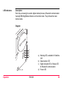
Introduction
2
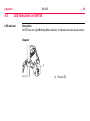
Introduction
Purchase
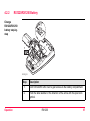
Congratulations on the purchase of an RX1200.
This manual contains important safety directions as well as instructions for setting
up the product and operating it. Refer to "7 Safety Directions" for further information.
Read carefully through the User Manual before you switch on the product.
Product
identification
The type and serial number of your product are indicated on the type plate.
Enter the type and serial number in your manual and always refer to this information
when you need to contact your agency or Leica Geosystems authorized service
workshop.
Type:
_______________
Serial No.:
_______________
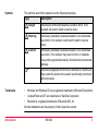
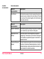
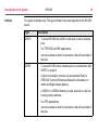
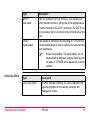
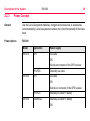
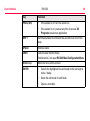
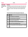
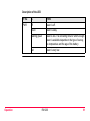
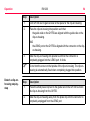
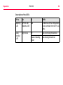
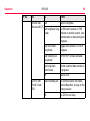
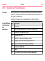
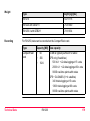
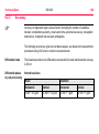
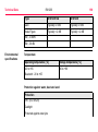
Symbols
The symbols used in this manual have the following meanings:
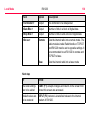
Type
Description
Danger
Indicates an imminently hazardous situation which, if not
avoided, will result in death or serious injury.
Warning
Indicates a potentially hazardous situation or an unintended
use which, if not avoided, could result in death or serious
injury.
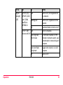
Caution
Indicates a potentially hazardous situation or an unintended
use which, if not avoided, may result in minor or moderate
injury and/or appreciable material, financial and environmental
damage.
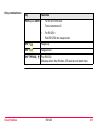
)
Trademarks
Important paragraphs which must be adhered to in practice as
they enable the product to be used in a technically correct and
efficient manner.
•
Windows and Windows CE are a registered trademark of Microsoft Corporation
•
CompactFlash and CF are trademarks of SanDisk Corporation
•
Bluetooth is a registered trademark of Bluetooth SIG, Inc
All other trademarks are the property of their respective owners.
Introduction
RX1200
3
RX1200
Table of Contents
4
Table of Contents
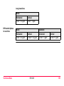
In this manual
Chapter
Page
1
How to Use this Manual
2
Description of the System
14
2.1
2.2
Terminology
System Concept
2.2.1
Software Concept
2.2.2
Data Storage and Data Conversion Concept
2.2.3
Power Concept
2.3 Transport Containers
2.3.1
Container Contents for the TPS Instrument
2.3.2
Container Contents for the GNSS Receiver
2.4 RX1200 Components
User Interface
14
20
20
25
28
30
30
33
35
38
3.1
3.2
3.3
3.4
38
42
44
45
3
Keyboard
Screen
Operating Principles
Icons
8
4
Operation
48
4.1
Equipment Setup
4.1.1
Fixing RX1200 to a Holder, Handstrap or GNSS Receiver
4.1.2
Setting up with the TPS Instrument
4.1.3
Setting up with the GNSS Receiver
4.2 Batteries
4.2.1
Operating Principles
4.2.2
RX1220/RX1250 Battery
4.2.3
SmartAntenna Battery
4.2.4
GHT56 Battery
4.3 Working with the CompactFlash Card
4.4 LED Indicators on SmartAntenna
4.5 LED Indicators on GHT56
4.6 Working with the Clip-On-Housings for Devices on GHT56
4.7 Basic Operation
4.8 Licence Keys
4.9 Guidelines for Correct Results with GNSS Surveys
4.10 RX1250 Connections
4.10.1
Connection to SmartAntenna
4.10.2
Connection to a Digital Cellular Phone
4.10.3
Connection to a Personal Computer
4.11 Working with the TPS Instrument
4.11.1
Working in Remote Mode
4.11.2
Working in Transparent Mode
Table of Contents
RX1200
48
48
59
62
65
65
67
69
71
73
78
80
82
94
100
103
104
104
106
108
114
114
115
5
RX1200
Table of Contents
5
4.11.3
Local Mode
Working in Semi-Transparent Mode
6
116
118
5.1
5.2
5.3
5.4
5.5
6
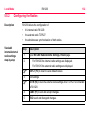
Accessing the Main Configuration Menu
Overview of the Main Configuration Menu
Choosing a Sensor
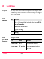
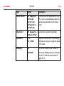
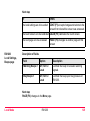
Local Settings
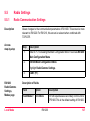
Radio Settings
5.5.1
Radio Communication Settings
5.5.2
Configuring the Radios
5.6 Working with a Sensor
Care and Transport
118
120
121
123
127
127
132
134
136
7
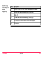
6.1 Transport
6.2 Storage
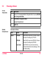
6.3 Cleaning and Drying
Safety Directions
136
137
138
140
7.1
7.2
7.3
7.4
7.5
7.6
7.7
140
141
143
144
146
148
151
General Introduction
Intended Use
Limits of Use
Responsibilities
International Warranty, Software Licence Agreement
End User Licence Agreement EULA
Hazards of Use
Table of Contents
8
7.8 Electromagnetic Compatibility EMC
7.9 FCC Statement, Applicable in U.S.
Trouble Shooting
157
160
170
9
Technical Data
178
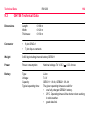
9.1
9.2
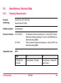
RX1200 Technical Data
SmartAntenna Technical Data
9.2.1
Tracking Characteristics
9.2.2
Accuracy
9.2.3
Technical Data
9.3 GHT56 Technical Data
9.4 Conformity to National Regulations
9.4.1
RX1220
9.4.2
RX1250
9.4.3
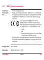
GFU16, Bluetooth communication
9.4.4
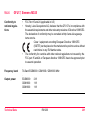
GFU17, Siemens MC45
9.4.5
GFU24, Siemens MC75
9.4.6
GFU19 (US), GFU25 (CAN) CDMA MultiTech MTMMC-C
9.4.7
SmartAntenna with Bluetooth
Appendix A Directory Structure of the Memory Device
178
183
183
186
188
192
195
195
197
199
201
203
205
207
210
Appendix B Cables
212
Index
216
RX1200
7
How to Use this Manual
1
RX1200
8
How to Use this Manual
)
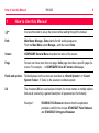
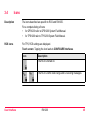
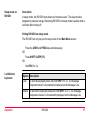
It is recommended to set-up the product while reading through this manual.
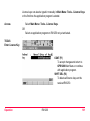
Path
Main Menu: Manage...\Data stands for this working sequence:
From the Main Menu select Manage... and then select Data.
Screen
CONFIGURE General Menu describes the name of the screen.
Page
Screens can have more than one page. Units page describes a specific page of a
screen. For example: ’...in CONFIGURE Units & Formats, Units page...’
Fields and options
Fields displayed on the screen are described as <Coord System:> or <Coord
System: Swiss>, if ’Swiss’ is the selected coordinate system.
XX
The characters XX are used as place holders for screen names or multiple options
that are all covered by a general description of appearance or functionality.
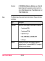
Example 1:
STAKEOUT XX Stakeout indicates that the explanation
provided is valid for the screens STAKEOUT Polar Stakeout
and STAKEOUT Orthogonal Stakeout.
Example 2:
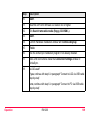
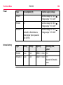
Keys
In REFLINE Define Reference, Reference page, <Task: XX
Line> indicates that the explanation provided is valid for the
options <Task: Measure to Line>, <Task: Stake to Line> and
<Task: Gridstake Line>.
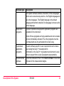
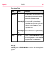
Two different types of keys can be found on the instrument. These are fixed keys
and softkeys.
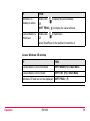
Type
Description
Fixed keys
Keys which can be pressed on the keyboard, for example:
• Function keys F1-F6.
• Function keys F7-F12.
• Alphanumeric keys.
• ESC, USER, PROG, CE, ENTER, SHIFT.
• Arrow keys.
Softkeys
How to Use this Manual
Displayed on the screen, can be selected by using the
assigned fixed key. For example CONT (F1). The assigned
fixed key is shown in brackets.
RX1200
9
How to Use this Manual
RX1200
10
)
Throughout the manual, stepwise instructions are used. Keys to be pressed within
these instructions are indicated, such as ENTER, CONT (F1) or SHIFT INDIV (F5).
Index
The index is at the end of the manual.
)
Keys, fields and options on the screens which are considered as self-explanatory are
not explained.
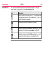
Validity of this
manual
•
This manual applies to all RX1200 instruments. Differences between the various
models are marked and described.
•
The RX1200 is available as RX1210 or with touch screen functionality as
RX1210T, RX1220T, RX1250 X. The names RX1210 and RX1220 are used
throughout the manual and may also represent the touch screen models. Only
use the supplied stylus on the screens of the touch screen models.
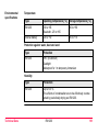
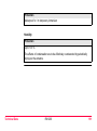
Available
documentation
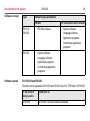
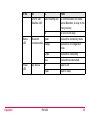
General description
Name of
documentation
Description
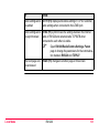
User Manual
All instructions required in order to operate the product to
a basic level are contained in the User Manual. Provides
an overview of the product together with technical data
and safety directions.
Name of
documentation
Description
System Field Manual
Describes the general working of the product in standard
use. Intended as a quick reference field guide.
Applications Field
Manual
Describes specific onboard application programs in
standard use. Intended as a quick reference field guide.
The RoadRunner application program is described in a
separate manual.
Technical Reference
Manual
Overall comprehensive guide to the product and program
functions. Included are detailed descriptions of special
software/hardware settings and software/hardware functions intended for technical specialists.
How to Use this Manual
RX1200
11
RX1200
How to Use this Manual
12
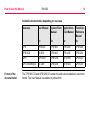
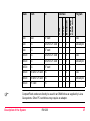
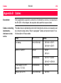
Available documentation depending on use case
Use case
Format of the
documentation
User Manual
System Field
Manual
Applications
Field Manual
Technical
Reference
Manual
for
for
for
for
TPS
TPS1200
TPS1200
TPS1200
TPS1200
TPS RCS
RX1200
TPS1200
TPS1200
TPS1200
GPS
GPS1200
GPS1200
GPS1200
GPS1200
GPS SmartRover
RX1200
GPS1200
GPS1200
GPS1200
The TPS1200 CD and GPS1200 CD contain the entire documentation in electronic
format. The User Manual is available in printed form.
How to Use this Manual
RX1200
13
Description of the System
2
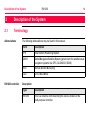
2.1
RX1200
14
Description of the System
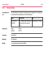
Terminology
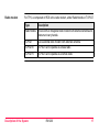
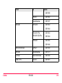
Abbreviations
RX1200 controller
The following abbreviations may be found in this manual:
Term
Description
TPS
Total Station Positioning System
GNSS
Global Navigation Satellite System (generic term for satellite based
navigation systems like GPS, GLONASS, SBAS)
RCS
Remote Control Surveying
LGO
LEICA Geo Office
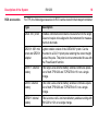
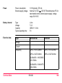
Description
Type
Description
RX1200
This is a collective term describing the various models of the
multi-purpose controller.
Type
Description
For TPS, a component of RCS is RX1200. TPS1200 instruments
can be used with these controllers and radio modems (RadioHandle or TCPS27) to form RCS.
For GPS, these controllers can be used with GPS instruments.
RX1250 can replace RX1210/RX1220 but not vice versa.
Radio module
Internal battery
CompactFlash
card
Bluetooth
Windows CE
Application
-
-
-
-
-
-
GX1200
-
RX1210T
x
-
-
-
-
-
GX1200
-
RX1220T
x
x
x
-
-
-
GX1200
RCS
RX1250 X
x
-
x
x
x
x
SmartAntenna
or GX1200
-
Description of the System
RX1200
For TPS
Touch screen
RX1210
For GPS
Models
Available models
15
RX1200
Description of the System
Holders
16
Two types of holders exist. The type of holder to be used depends on the RX1200
model.
Type
Description
GHT39
•
GHT56
To mount RX1200 on a GLS11 prism pole or on an antenna
pole.
•
For TPS RCS and GPS applications.
•
Can be reversed so that it is mounted on the left hand side of
the pole.
•
To mount RX1250 on an antenna pole or in combination with
GHT57 on a tripod.
•
A clip-on-housing for a device can be attached. Refer to
GPS1200 Technical Reference Manual for information on
radios and digital cellular phones.
•
A GEB211 or GEB221 battery to power a device in a clip-onhousing can be attached.
•
For GPS applications.
•
Can be reversed so that it is mounted on the left hand side of
the pole.
Radio modem
For TPS, a component of RCS is the radio modem, either RadioHandle or TCPS27.
Type
Description
RadioHandle
This is both an integrated radio modem with attached antenna and
instrument carry handle.
TCPS27
Leica external radio modem with attached antenna.
TCPS27B
TCPS27 set to operate as a base radio.
TCPS27R
TCPS27 set to operate as a remote radio.
Description of the System
RX1200
17
Description of the System
RCS accessories
RX1200
18
For TPS, the following accessories for RCS can be stored in the transport container:
Type
Description
GRZ4 360° prism
Enables omnidirectional distance measurement to the target.
Does not require to be aligned to the instrument for measurements to be made.
GRZ101 360° mini Lighter smaller version of the GRZ4 360° prism. Can be
prism and GRZ101 mounted to a GLS11 prism pole retaining the correct height
scale of the pole. This prism is not recommended for use with
adapter
the PowerSearch function.
GEB171 external
battery
This large Leica external battery enables continuous operation of both TPS1200 and TCPS27B for 18 h on a single
charge.
GEB70 external
battery
This small Leica external battery enables continuous operation of both TPS1200 and TCPS27B for 5 h on a single
charge.
GEB211 internal
battery
This Leica two cell Li-Ion internal battery enables working with
RX1220 for 12 h on a single charge.
Type
Description
GHT39
pole holder
This unit enables RX1210 or RX1220T to be mounted on
either the antenna pole or, with the use of the supplied sleeve,
it can be mounted on the GLS11 prism pole. The GHT39 can
be reversed so that it is mounted on the left hand side of the
pole.
GHT43
tripod adapter
This adapter is intended for the mounting of TCPS27B to all
Leica standard tripods in order to optimise the radio transmission performance.
Scope of adjustability. The tripod adapter can be
adjusted both up and down along the tripod leg, and
the angle of TCPS27B can be adjusted to a vertical
position.
)
LEICA Geo Office
Type
Description
LEICA Geo Office:
An office software consisting of a suite of standard and
extended programs for the viewing, exchange and
management of data.
Description of the System
RX1200
19
Description of the System
2.2
System Concept
2.2.1
Software Concept
Description
Software type
RX1200
20
The software concept depends on the RX1200 model.
The various types of software are explained in paragraph "Software type".
The software concept for the RX1200 models is explained in paragraph "Software
concept".
Software type
Description
RX1200
software
For RX1210 and RX1220T. This software covers display, sound
and communication settings of the RX1210 and RX1220T.
System
software
This important software covers the basic functions of the instrument. System software is also referred to as firmware.
The programs Survey and Setup are integrated into the firmware
and cannot be deleted.
The English language is integrated into the firmware and cannot
be deleted.
Language
software
Numerous languages are available for the receivers. Language
software is also referred to as system language.
Software type
Description
The system software enables a maximum of three languages
which can be stored at any one time - the English language and
two other languages. The English language is the default
language and cannot be deleted. One language is chosen as the
active language.
Application
programs
A suite of optional survey-specific application programs are
available for the instrument.
Some of these programs are freely available and can be loaded
and are immediately activated. The other programs must be
purchased and are only activated with a licence key.
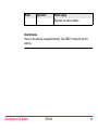
Customised
application
programs
Custom software specific to user requirements can be developed using the GeoC++ development kit.
Information on the GeoC++ development environment is available on request from a Leica Geosystems representative.
SmartAntenna
software
This is the software for the ATX1230/ATX1230 GG. It covers the
firmware for the measurement engine.
Description of the System
RX1200
21
RX1200
Description of the System
Software concept
Type
Software type uploaded to
RX1200
TPS instrument / GPS receiver
RX1210/
RX1220
•
•
System software
•
Language software
•
Application programs
•
Customised application
programs
RX1250
Software upload
22
RX1200 software
•
System software
•
Language software
•
Application programs
•
Customised application
programs
-
For RX1210 and RX1220
Firmware can be uploaded to RX1210 and RX1220 via LGO, TPS1200 or GPS1200.
IF the product
being used is
THEN refer to
TPS1200
GPS1200 Technical Reference Manual.
IF the product
being used is
THEN refer to
GPS1200
TPS1200 Technical Reference Manual.
LGO
online help in LGO.
For RX1250
All software is stored in the System RAM of the RX1250. The software can be
uploaded onto a CompactFlash card in the RX1250 using the methods listed in the
table below.
After uploading, the software must then be transferred from the CompactFlash card
to the RX1250 System RAM. Refer to GPS1200 Technical Reference Manual for
information.
Description of the System
RX1200
23
RX1200
Description of the System
24
RX1250 CF card
PC
RX1250 CF card
x
-
x
-
ActiveSync
PC
CF card
-
-
-
x
-
Card slot/
OMNI drive
PC
Bluetooth
Interface
Serial
To
USB
From
x
x
x
-
Program
Refer to
chapter
LGO
online help in
LGO
Microsoft ActiveSync is the synchronization software for Windows mobile-based
pocket PC’s. Microsoft ActiveSync enables a PC and a Windows mobile-based
pocket PC to communicate.
For SmartAntenna
SmartAntenna must always be connected to RX1250 when uploading the firmware.
Connect SmartAntenna and RX1250 via cable.
Uploading the firmware takes some time.
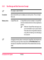
2.2.2
Data Storage and Data Conversion Concept
)
This chapter is valid for RX1250.
Description
Data is stored within a job in a database on a memory device. This is a CompactFlash card.
Memory device
CompactFlash card:
A CompactFlash card slot is standard. A CompactFlash
card can be inserted and removed. Various capacities are
available.
Whilst other CompactFlash cards may be used,
Leica recommends to only use Leica CompactFlash cards and is not responsible for data loss
or any other error that may occur whilst using a
non-Leica card.
)
)
Unplugging connecting cables or removing the CompactFlash card during the measurement may cause loss of data. Always return to GPS1200 Main Menu before
removing the CompactFlash card and switch off the instrument before removing
cables.
Description of the System
RX1200
25
RX1200
Description of the System
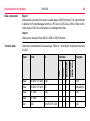
Data conversion
26
Export
Data can be exported from a job in a wide range of ASCII formats. The export format
is defined in Format Manager which is a PC tool in LEICA Geo Office. Refer to the
online help of LGO for information on creating format files.
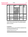
Import
Data can be imported from ASCII, GSI8 or GSI16 format.
Data
From
Serial
Bluetooth
Card slot/
OMNI drive
Data can be transferred in various ways. Refer to " ActiveSync" and the online help
of LGO.
USB
Transfer data
To
Interface
Program
Raw
RX1250 CF card LGO
x
x
x
-
LGO
Raw
RX1250 CF card PC
x
-
x
-
ActiveSync
Raw
CF card
LGO
-
-
-
x
LGO
Raw
CF card
PC
-
-
-
x
-
Job
LGO
RX1250 CF card x
x
x
-
LGO
)
LGO
CF card
Program
Card slot/
OMNI drive
Job
Interface
Bluetooth
To
Serial
From
USB
Data
-
-
-
x
LGO
Job
PC
RX1250 CF card x
-
x
-
ActiveSync
Job
PC
CF card
-
-
-
x
-
ASCII
PC
RX1250 CF card x
x
x
-
LGO
ASCII
PC
RX1250 CF card x
-
x
-
ActiveSync
ASCII
PC
CF card
ASCII
RX1250 CF card PC
ASCII
RX1250 CF card PC
x
-
x
-
ActiveSync
ASCII
CF card
-
-
-
x
-
PC
-
-
-
x
-
x
x
x
-
LGO
CompactFlash cards can directly be used in an OMNI drive as supplied by Leica
Geosystems. Other PC card drives may require an adaptor.
Description of the System
RX1200
27
RX1200
Description of the System
2.2.3
28
Power Concept
General
Use the Leica Geosystems batteries, chargers and accessories or accessories
recommended by Leica Geosystems to ensure the correct functionality of the instrument.
Power options
RX1200
Model
Application
Power supply
RX1210
GPS
Via cable
OR
Via clip-on connector of the GPS receiver
RX1220
TPS RCS
Externally via cable
GPS
Via cable
OR
Vial clip-on connector of the GPS receiver
RX1250
TPS RCS
Internally via GEB211 battery
SmartRover
Internally via GEB211 battery
OR
Model
Application
Power supply
Externally via cable to battery.
SmartAntenna
Power for the antenna is supplied internally. One GEB211 battery fits into the
antenna.
Description of the System
RX1200
29
RX1200
Description of the System
2.3
Transport Containers
2.3.1
Container Contents for the TPS Instrument
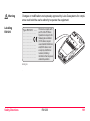
Description
30
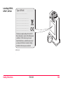
Components for RCS and SmartStation are combined in one transport container.
Term
Description
SmartStation
A TPS1200 instrument integrated with an add-on GPS system,
comprising hardware and software components, forms
SmartStation.
Components of SmartStation include SmartAntenna,
SmartAntenna Adapter with attached clip-on-housing and antenna
for a communication device and Communication side cover (not
included in transport container).
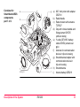
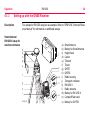
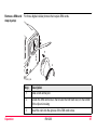
Container for
SmartStation/RCS
components
part 1 of 2
a
g
b
c
d
e
h
i
f
RX12_012
Description of the System
RX1200
a) 360° mini prism with adapter
GRZ101
b) RadioHandle
c) Radio modem with antenna
TCPS27
d) Grip with circular bubble and
fixing element GHT25
(without clamp)
e) Y-cable GEV186 / battery
cable GEV52 (stored over
grip)
f) Antenna for communication
device in clip-on-housing
g) SmartAntenna Adapter with
communication device in
clip-on-housing
h) SmartAntenna
i) Internal battery GEB211
31
Description of the System
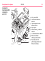
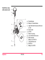
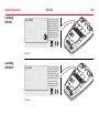
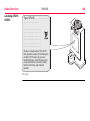
Container for
SmartStation/RCS
components
part 2 of 2
RX1200
32
a
b
e
c
d
RX12_004
a) 360° prism GRZ4
b) User manual and other
manuals
c) Tripod adapter for radio
modem GHT43
d) Spare stylus
e) External battery - GEB70 or
GEB171
f f) 2 x internal batteries GEB211
g) RX1220 controller
g
with stylus and antenna
h) Pole holder GHT39
h
(with clamp) (stored under
RX1220 controller)
2.3.2
Container Contents for the GNSS Receiver
Description
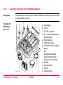
Container for
SmartRover
part 1 of 2
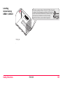
Components for a two component cableless GNSS real-time system are combined
in one transport container.
a b
c
d
e
f
a)
b)
c)
d)
e)
f)
g)
g
GPS12_151a
Description of the System
h
i
RX1200
j
k
h)
i)
j)
k)
Adjusting pin
GHT57
90° TNC conenctor
Arm 15 cm long, attaches to
SmartAntenna
Spare batteries
Antennas of device
GHT56 with device, without
battery
OR
SmartAntenna Adapterwithout communication
device in clip-on-housing
RX1250
SmartAntenna
Cables
Supplied stylus
33
RX1200
Description of the System
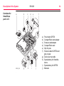
Container for
SmartRover
part 2 of 2
a
b
c
d
34
f
e
a)
b)
c)
d)
e)
f)
GPS12_152
g
h
i
j
Pole holder GHT39
CompactFlash card adapter
Screw-to-stub adapter
CompactFlash card
Grip for pole
Screw to attach GHT39 and
grip on pole
g) Device such as radio
h) Spare battery for SmartAntenna
i) Spare battery for GHT56
j) Manuals
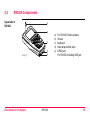
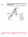
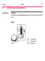
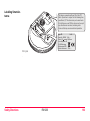
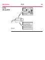
2.4
RX1200 Components
Upperside of
RX1200
a
b
c
RX12_017
Description of the System
d
e
RX1200
a)
b)
c)
d)
e)
For RX1220: Radio antenna
Screen
Keyboard
Hand strap bottom clips
LEMO port
For RX1250 including USB port
35
RX1200
Description of the System
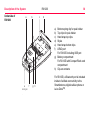
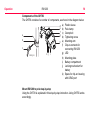
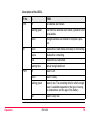
Underside of
RX1200
a
b
c
36
d
a)
b)
c)
d)
e)
f)
Bottom spring clip for pole holder
Top clips for pole holder
Hand strap top clips
Stylus
Hand strap bottom clips
LEMO port
For RX1250 including USB port
g) Battery compartment
For RX1250 with CompactFlash card
compartment
h) Clip-on-contacts
e
RX12_002
f
g h
For RX1250, a Bluetooth port is included
inside to facilitate connectivity to the
SmartAntenna, digital cellular phone or
Leica DistoTM.
Description of the System
RX1200
37
RX1200
User Interface
3
3.1
38
User Interface
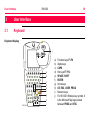
Keyboard
Keyboard display
ESC
j
PROG
OFF
F1
Q
W
A
F2
E
S
Z
F
C
F8
F4
T
D
X
F7
F3
R
G
V
F5
Y
U
H
B
SPACE
F9
F6
I
J
N
F10
K
L
CAPS
M
F11
SHIFT
7
8
4
5
1
6
2
0
PgUp
9
PgDn
3
.
F12
a
b
c
d
e
f
g
ESC
CE
USER
PROG
OFF
RX12_001
P
O
ON
ON
h
i
a)
b)
c)
d)
e)
f)
g)
h)
i)
j)
Function keys F1-F6
Alpha keys
CAPS
Hot keys F7-F12
SPACE, SHIFT
ENTER
Arrow keys
CE, ESC, USER, PROG
Numeric keys
For RX1250: Windows key symbol. It
is the Microsoft flag logo located
between PROG and ESC.
)
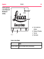
Keys
For the purpose of the illustration, a RX1250 model has been selected which is
representative for all models. Differences to other RX1200 models are outlined.
Key
Function
Function keys
F1-F6
Correspond to six softkeys that appear on the bottom of the
screen when the screen is activated.
Hot keys
F7-F12
User definable keys to execute chosen commands or access
chosen screens.
Alpha keys
To type letters.
Numeric keys
To type numbers.
CAPS
Switches between upper case and lower case letters.
CE
•
Clears all entry at the beginning of user input.
•
Clears the last character during user input.
•
Leaves the current menu or dialogue without storing any
changes made.
•
Turns receiver off when hold for 2 s in GPS1200 Main
Menu.
ESC
User Interface
RX1200
39
RX1200
User Interface
Key
PROG (ON)
40
Function
•
If the sensor is off: turn the sensor on.
•
If the sensor is on: press at any time to access XX
Programs to select an application.
SHIFT
Switches between the first and the second level of function
keys.
SPACE
Enters a blank.
USER
Calls the user defined menu.
Hold down for 2 s to open RX1200 Main Configuration Menu.
Arrow keys
Move the focus on the screen.
ENTER
•
Selects the highlighted line and leads to the next logical
menu / dialog.
•
Starts the edit mode for edit fields.
•
Opens a choicelist.
Key combinations
Key
Function
PROG plus USER •
For RX1210/RX1220:
Turns instrument off.
•
For RX1250:
Puts RX1250 into sleep mode.
SHIFT
Pages up.
SHIFT
Pages down.
SHIFT PROG (
User Interface
) For RX1250:
Displays either the Windows CE task bar and start menu.
RX1200
41
RX1200
User Interface
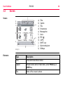
3.2
42
Screen
Screen
f
a
b
c
g
d
h
i
j
e
k
RX12_013
Elements
a)
b)
c)
d)
e)
f)
g)
h)
i)
j)
k)
Time
Caption
Title
Screen area
Message line
Icons
ESC
CAPS
SHIFT icon
Quick coding icon
Softkeys
Type
Description
Time
The current local time is shown.
Caption
Shows location either in Main Menu, under PROG key or
USER key.
Title
Name of the screen is shown.
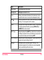
Type
Description
Screen area
The working area of the screen.
Message line
Messages are shown for 10 s.
Icons
Shows current status information of the instrument. Can be
used with touch screen to access the subsequent screen.
ESC
Can be used with touch screen. Same functionality as the ESC
fixed key. The last operation will be undone.
CAPS
The caps mode for upper case letters is active.The caps mode
is activated and deactivated by pressing UPPER (F5) or
LOWER (F5) in some screens.
SHIFT icon
Shows the status of the SHIFT key; either first or second level
of softkeys is selected. Can be used with touch screen and has
the same functionality as the fixed key SHIFT.
Quick coding icon Shows the quick coding configuration. Can be used with touch
screen to turn quick coding on and off.
Softkeys
User Interface
Commands can be executed using F1 - F6 keys. The
commands assigned to the softkeys are screen dependent.
Can be used directly with touch screen.
RX1200
43
RX1200
User Interface
3.3
44
Operating Principles
Keyboard and
touch screen
The user interface is operated either by the keyboard or by the touch screen with
supplied stylus. The workflow is the same for keyboard and touch screen entry, the
only difference lies in the way information is selected and entered.
Operation by keyboard
Information is selected and entered using the keys. Refer to "3.1 Keyboard" for a
detailed description of the keys on the keyboard and their function.
Operation by touch screen
Information is selected and entered on the screen using the supplied stylus.
Operation
Description
To select an item
Tap on the item.
To start the edit mode in input fields
Tap on the input field.
To highlight an item or parts of it for
editing
Drag the supplied stylus from the left to
the right.
To accept data entered into an input field Tap on the screen outside of the input
and exit the edit mode
field.
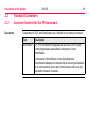
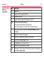
3.4
Icons
Description
The icons described are specific to RCS and RX1250.
For a complete listing of icons
• for GPS1200 refer to GPS1200 System Field Manual.
•
RCS icons
for TPS1200 refer to TPS1200 System Field Manual.
For TPS, RCS settings are displayed.
Touch screen: Tapping the icon leads to CONFIGURE Interfaces.
Icon
Description
The RCS is turned on.
The RCS is within radio range and is receiving messages.
User Interface
RX1200
45
RX1200
User Interface
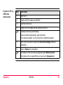
Bluetooth icons
46
The status of each Bluetooth port and any Bluetooth connection is displayed.
Touch screen: Tapping the icon leads to STATUS Bluetooth.
Icon
Description
RX1250, GNSS receiver with GFU16 or TPS instrument with
Communication side cover is Bluetooth capable. In case of a
RX1250, Bluetooth is integrated.
A Bluetooth connection is established and active.
Bluetooth connection not established. Bluetooth port 1, 2 and
3 are down. Port 2 and 3 are only available on RX1250.
Bluetooth connection established. Bluetooth port 1, 2 and 3
are active. Port 2 and 3 are only available on RX1250.
Battery icons
The status and source of the battery is displayed. The remaining power in the battery
is indicated by six levels.
For RX1250: If an external power supply is connected and one internal battery is
inserted, then the external power is used.
Touch screen: Tapping the icon leads to STATUS Battery & Memory, Battery
page.
Icon
Description
For RX1250: Internal battery is in use.
For RX1250: External battery attached and in use.
For TPS1200 instruments: Internal TPS and RCS batteries are
in use.
For TPS1200 instruments: External TPS and RCS batteries
are in use.
User Interface
RX1200
47
RX1200
Operation
4
Operation
4.1
Equipment Setup
4.1.1
Fixing RX1200 to a Holder, Handstrap or GNSS Receiver
Description
RX1200 can be set up using
• a holder on the pole.
•
GNSS receiver.
•
a handstrap.
All three setups are described in this chapter.
48
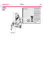
Holders
Components of the GHT39
The GHT39 consists of a number of components, as shown in the diagram below.
d
a
e a)
b
b)
c)
d)
e)
f)
f
c
RX12_005
Operation
RX1200
Plastic sleeve
Pole clamp
Clamp bolt
Tightening screw
Mounting plate
Mounting arm
49
RX1200
Operation
50
Components of the GHT56
The GHT56 consists of a number of components, as shown in the diagram below.
d a)
e b)
f c)
g
a
d)
b
h e)
f)
c
RX12_016
k j
i
g)
h)
i)
j)
k)
Plastic sleeve
Pole clamp
Clamp bolt
Tightening screw
Mounting arm
Clip-on-contacts for
connecting RX1250
LED
Mounting plate
Battery compartment
Locking mechanism for
battery
Space for clip-on-housing
with LEMO port
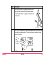
Mount RX1200 to pole step-by-step
Using the GHT39 is explained in this step-by-step instruction. Using GHT56 works
accordingly.
Step
Remove holder from the travel container.
2.
For GLS11 pole: the plastic sleeve is to be fitted to the pole clamp.
For GPS pole: the plastic sleeve is not required.
3.
Insert pole into the clamp hole.
4.
Adjust the angle of the mounting plate and the height of the holder on the
pole to comfort.
5.
Tighten the clamp with the tightening screw.
)
)
Operation
Description
1.
Once tightened, the button on the tightening screw can be depressed to
change the position of the handle for more comfort.
A locking mechanism is incorporated in the mounting plate of the holder.
RX1200
51
RX1200
Operation
Step
52
Description
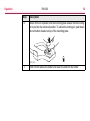
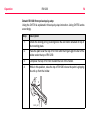
6.
Before RX1200 is placed onto the mounting plate ensure that the locking
pin is put into the unlocked position. To unlock the locking pin, push down
the red button situated on top of the mounting plate.
7.
Hold RX1200 above the holder and lower the end into the holder.
RX12_015
Step
Description
8.
Apply slight pressure in a downward direction and
then lower the top part of RX1200 until the unit is
clicked into the holder. The guides of the holder aid
in this action.
9.
After RX1200 is placed onto the mounting plate ensure that the locking pin
is put into the locked position. To lock the locking pin, push up the red
button from below.
RX12_006
RX12_014
Operation
RX1200
53
RX1200
Operation
54
Detach RX1200 from pole step-by-step
Using the GHT39 is explained in this step-by-step instruction. Using GHT56 works
accordingly.
Step
Description
1.
Unlock the locking pin by pushing down the red button situated on top of
the mounting plate.
2.
Place the palm over the top of RX1200 until the fingers grip the bar of the
holder under the top of RX1200.
3.
Compress the top of RX1200 toward the bar of the holder.
4.
While in this position, raise the top of RX1200 where the palm is gripping
the unit up from the holder.
1
2
RX12_007
GPS receiver
Description
RX1210, RX1220 and RX1250 can be mounted to a GNSS receiver.
Mount RX1210/RX1220/RX1250 to GNSS receiver step-by-step
Step
Description
1.
Hold RX1200 above the recess in the
housing of the GNSS receiver intended
for the unit.
2.
Lower the bottom part of RX1200 into
the recess in the housing of the GNSS
receiver.
3.
Apply slight pressure in a downward
direction and then lower the top part of
RX1200 until the unit is clicked into the
GNSS receiver. The recess in the
housing of the GNSS receiver helps to
guide RX1200.
2
1
RX12_008
Operation
RX1200
55
RX1200
Operation
Detach RX1210/RX1220T from GNSS receiver step-by-step
Step
Description
1.
Place the palm over the top of RX1200.
2.
Compress RX1200 downward toward the ports of the GNSS receiver.
3.
While in this position, raise the top of RX1200 from the GNSS receiver.
RX12_009
56
Handstrap
Mount handstrap to RX1200 step-by-step
Step
)
Description
1
2
3
RX12_003
Operation
1.
Hold the main hook rotated to approximately the 11 o'clock position in relation to RX1200.
2.
Lower the main hook onto the pivot knob in the middle of RX1200.
3.
Rotate the main hook to the 12 o'clock position. A click should be felt when
the clip is secure.
RX1200
57
RX1200
Operation
Step
4.
Description
Take the other end of the handstrap and clip it to the base of RX1200.
58
4.1.2
Setting up with the TPS Instrument
TPS1200/RX1200
setup for RCS
with RadioHandle
Refer to "TPS1200 User Manual" for additional information on RadioHandle.
e
a
f
g
b
h
c
a)
b)
c)
d)
e)
f)
g)
h)
d
RX12_013
Operation
RX1200
360° prism
Prism pole
RX1220
RX1200 holder and pole clamp
RadioHandle
Communication side cover
TPS1200 instrument
Tripod
59
RX1200
Operation
Step
Description
1.
Attach TCPS27B to the adapter and then attach to the tripod leg.
2.
Adjust the angle of TCPS27B until it is approximately vertical.
3.
Adjust the location of the adapter on the tripod leg so that there are no
metallic objects in the horizontal plane around the antenna.
Metallic objects near the antenna disturb transmissions from the
radio.
To achieve the best performance from
TCPS27B, it should be mounted in a vertical
position on the tripod leg approximately
30 cm from the top of the tripod.
cm
)
)
~ 30
Mount base radio
to tripod
step-by-step
60
)
RX12_010
If the adapter is no longer able to retain it’s angle position, the adjustment
bolt at the hinge can be slightly tightened.
TPS1200/RX1200
setup for RCS
with TCPS27
a
e
b
f
g
c
d
h
a)
b)
c)
d)
e)
f)
g)
h)
i)
i
RX12_011
Operation
RX1200
360° prism
Prism pole
RX1220
RX1200 holder and pole clamp
TPS1200 instrument
Tripod
TCPS27B
External battery
Y-cable
61
RX1200
Operation
4.1.3
62
Setting up with the GNSS Receiver
Description
Two setups for RX1250 are given as example. Refer to "GPS1200 Technical Reference Manual" for information on additional setups.
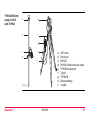
SmartAntenna/
RX1250 X setup for
real-time reference
a
b
c
d
e
f
g
j
k
l
m
n
h
i
RX12_28
o
a)
b)
c)
d)
e)
f)
g)
h)
i)
j)
k)
l)
m)
n)
o)
SmartAntenna
Battery for SmartAntenna
Height hook
Carrier
Tribrach
Tripod
GHT57
GHT56
Radio housing
Transport container
RX1250 X
Radio antenna
Battery for RX1250 X
CompactFlash card
Battery for GHT56
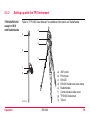
SmartRover setup
with external radio
a
b
c
h
i
d
j
e
k
f
l
g
RX12_31
Operation
RX1200
a) SmartAntenna
b) Battery for SmartAntenna
c) Upper half aluminium pole with screw
or stub
d) Grip for pole
e) GHT56
f) Radio in housing
g) Lower half aluminium pole
h) Radio antenna
i) Battery for RX1250 X
j) CompactFlash card
k) RX1250 X
l) Battery for GHT56
63
RX1200
Operation
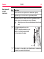
Increase radio
coverage on SmartRover
64
Description
Some applications require the maximum radio coverage. In those cases the radio
antenna is mounted on an antenna arm which is fixed to the pole just below the
SmartAntenna. Connection is made between the radio housing and the radio
antenna.
Connect radio antenna and radio housing using cable step-by-step
Step
1.
Description
Clip the antenna arm to the SmartAntenna.
2.
Screw the radio antenna onto the antenna arm.
3.
Attach the radio in its housing to GHT56.
4.
Place the battery into the battery compartment of the GHT56.
5.
Attach GHT56 to the pole and tighten the screw.
6.
Connect the radio antenna to the radio housing using the 1.2 m antenna
cable.
4.2
Batteries
4.2.1
Operating Principles
)
)
Operation
This chapter is valid for RX1220, RX1250 and GHT56.
Primary use/charging
• The battery must be charged prior to using it for the first time because it is delivered with an energy content as low as possible.
•
For new batteries or batteries that have been stored for a long time (> three
months), it is effectual to make only one charge/discharge cycle.
•
For Li-Ion batteries, a single discharging and charging cycle is sufficient. We
recommend carrying out the process when the battery capacity indicated on the
charger or on a Leica Geosystems product deviates significantly from the actual
battery capacity available.
•
The permissible temperature range for charging is between 0°C to +40°C/ +32°F
to +104°F. For optimal charging we recommend charging the batteries at a low
ambient temperature of +10°C to +20°C/+50°F to +68°F if possible.
•
It is normal for the battery to become warm during charging. Using the chargers
recommended by Leica Geosystems, it is not possible to charge the battery if
the temperature is too high.
RX1200
65
RX1200
Operation
66
Operation/Discharging
• The batteries can be operated from -20°C to +55°C/-4°F to +131°F.
•
Low operating temperatures reduce the capacity that can be drawn; very high
operating temperatures reduce the service life of the battery.
4.2.2
RX1220/RX1250 Battery
Change
RX1220/RX1250
battery step-bystep
2
4
5
3
6
RX12_018
f
Step
Operation
Description
1.
Turn RX1220/RX1250 over to gain access to the battery compartment.
2.
Push the slide fastener in the direction of the arrow with the open-lock
symbol.
RX1200
67
RX1200
Operation
Step
68
Description
3.
Open the battery compartment.
4.
Pull the battery from the battery compartment.
5.
A pictogram of the battery is displayed inside the battery compartment.
This is a visual aid to assist in placing the battery correctly.
6.
Place the battery into the battery compartment with the Leica logo facing
to the left.
7.
Close the battery compartment by pushing the slide fastener in the direction of the arrow with the close-lock symbol.
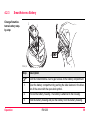
4.2.3
SmartAntenna Battery
Change SmartAntenna battery stepby-step
1
2
3
4
TPS12_193
Step
)
Operation
Description
Turn the SmartAntenna over to gain access to the battery compartment.
1.
Open the battery compartment by pushing the slide fastener in the direction of the arrow with the open-lock symbol.
2.
Pull out the battery housing. The battery is attached to the housing.
3.
Hold the battery housing and pull the battery from the battery housing.
RX1200
69
RX1200
Operation
Step
70
Description
4.
A polarity of the battery is displayed inside the battery housing. This is a
visual aid to assist in placing the battery correctly.
5.
Place the battery onto the battery housing, ensuring that the contacts are
facing outward. Click the battery into position.
6.
Close the battery compartment by pushing the slide fastener in the direction of the arrow with the close-lock symbol.
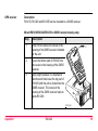
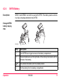
4.2.4
GHT56 Battery
Description
GEB211 and GEB221 can both be used with GHT56. The battery powers a device
in a clip-on-housing attached to the GHT56.
Change GHT56
battery step-bystep
3
2
5
6 6
2
RX12_022
f
Step
1.
Turn GHT56 over to gain access to the battery compartment.
2.
Press simultaneously on the right side of the locking mechanism and the
left side of the battery.
)
3.
Operation
Description
This unlocks the battery from its locked position.
Pull the battery from the battery compartment.
RX1200
71
RX1200
Operation
Step
4.
)
5.
)
72
Description
Place the battery into the battery compartment.
Ensure that the battery is placed adjacent to the locking mechanisam with
the contacts facing down.
Press simultaneously on the right side of the locking mechanism and the
right side of the battery.
This locks the battery into position.
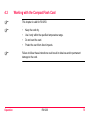
4.3
)
)
)
Operation
Working with the CompactFlash Card
This chapter is valid for RX1250.
•
Keep the card dry.
•
Use it only within the specified temperature range.
•
Do not bend the card.
•
Protect the card from direct impacts.
Failure to follow these instructions could result in data loss and/or permanent
damage to the card.
RX1200
73
RX1200
Operation
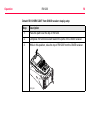
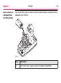
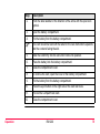
Insert and remove
a CompactFlash
card step-by-step
74
The CompactFlash card is inserted into a slot inside the battery compartment on the
underside of the RX1250.
2
4
3
11
10
RX12_019
Step
1.
Description
Turn RX1250 over to gain access to the battery compartment.
Step
2.
Push the slide fastener in the direction of the arrow with the open-lock
symbol.
3.
Open the battery compartment.
4.
Pull the battery from the battery compartment.
)
The card should be held with the label for the care instructions upwards
and the contacts facing the slot.
5.
Slide the card firmly into the slot until it clicks into position.
6.
Place the battery into the battery compartment.
7.
Close the compartment cover.
8.
To remove the card, open the cover of the battery compartment.
9.
10.
Operation
Description
Pull the battery from the battery compartment.
Press the eject button on the right side of the card slot twice.
11.
Pull out the CompactFlash card.
12.
Close the compartment cover.
RX1200
75
RX1200
Operation
Format a CompactFlash card step-bystep
76
Formatting the CompactFlash card before logging data is started is required if a
completely new CompactFlash card is used or if all existing data needs to be
deleted.
Step
Description
1.
Select Main Menu: Tools...\Format Memory Device.
2.
TOOLS Format Memory Device
<Memory Device: CF Card>
<Format Method: Format Quick>
)
)
Select the memory device to be formatted.
By activating the format command all data will be lost. Make sure that all
important data on the CompactFlash card has been backed up before
formatting the card. Before formatting the internal memory make sure that
all important data is first transferred to the PC.
To exit the screen without formatting the memory device, press ESC. This
returns to the previous screen.
3.
CONT (F1)
4.
YES (F4) to continue with the formatting of the selected device.
Step
)
5.
Operation
Description
NO (F6) to not continue with the formatting of the selected device and to
return to TOOLS Format Memory Device.
Once the formatting of the card is completed the system returns to
GPS1200 Main Menu.
RX1200
77
RX1200
Operation
4.4
78
LED Indicators on SmartAntenna
LED indicators
Description
SmartAntenna has Light Emitting Diode indicators. They indicate the basic antenna
status.
Diagram
BT
TRK PWR
K
R
T
GPS12_153
T
B
R
ON
OFF
W
P
TRK
BT
PWR
Tracking LED
Bluetooth LED
Power LED
Description of the LED’s
IF the
TRK
BT
PWR
Operation
is
THEN
off
no satellites are tracked.
flashing green
less than four satellites are tracked, a position is not
yet available.
green
enough satellites are tracked to compute a position.
green
Bluetooth is in data mode and ready for connecting.
purple
Bluetooth is connecting.
blue
Bluetooth has connected.
flashing blue
data is being transferred
off
power is off.
green
power is okay.
flashing green
power is low. The remaining time for which enough
power is available depends on the type of survey,
the temperature and the age of the battery.
red
power is very low.
RX1200
79
RX1200
Operation
4.5
80
LED Indicators on GHT56
LED indicator
Description
GHT56 has one Light Emitting Diode indicator. It indicates the basic power status.
Diagram
a
RX12_021
a) Power LED
Description of the LED
Operation
IF the
is
THEN
PWR
off
power is off.
green
power is okay.
flashing green
power is low. The remaining time for which enough
power is available depends on the type of survey,
the temperature and the age of the battery.
red
power is very low.
RX1200
81
RX1200
Operation
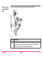
4.6
82
Working with the Clip-On-Housings for Devices on GHT56
Devices fitting into
a clip-on-housing
Digital cellular phones fitting into a clip-on-housing
Digital cellular phone
Clip-on-housing
Siemens MC45
GFU17
Siemens MC75
GFU24
CDMA MultiTech MTMMC-C (US)
GFU19
CDMA MultiTech MTMMC-C (CAN)
GFU25
Radios fitting into a clip-on-housing
Radio
Clip-on-housing
Pacific Crest PDL, receive
GFU15
Satelline 3AS, transceive
GFU14
Attach a clip-onhousing step-bystep
The clip-on-housing for devices fits to the underside of the GHT56.
RX12_020
Step
)
Operation
Description
A circular screw is located at one end of the clip-on-housing. Ensure that
the circular screw is in the unlocked position. Turn it anticlockwise, as
shown by the lock and arrow symbols on the screw.
RX1200
83
RX1200
Operation
Step
84
Description
1.
Turn GHT56 over to gain access to the space for the clip-on-housing.
2.
Place the clip-on-housing into position such that
• the guide rails on the GHT56 are aligned with the guide rails on the
clip-on-housing.
AND
• the LEMO port on the GHT56 is aligned with the connector on the clipon-housing.
3.
Detach a clip-onhousing step-bystep
Slide the clip-on-housing into position such that the connector is
completely plugged into the LEMO port. It clicks.
)
Do not turn the screw on the topside of the clip-on-housing. The clip-onhousing is automatically fixed when completely plugged into position.
Step
Description
1.
Press the small press clip next to the guide rail on the GHT56 to unlock
the clip-on-housing from the GHT56.
2.
Slide the clip-on-housing away from the press clip until the connector is
completely unplugged from the LEMO port.
Step
3.
Insert a SIM card
step-by-step
Operation
Description
Pull the clip-on-housing from the GHT56.
For those digital cellular phones that require SIM cards.
Step
Description
1.
Take the SIM card, a coin and a pen.
2.
Locate the SIM card screw, that covers the SIM card slot, on the bottom
of the clip-on-housing.
3.
Insert the coin into the groove of the SIM card screw.
4.
Turn the coin anticlockwise to loosen the SIM card screw.
5.
Remove the SIM card screw from the housing.
6.
Using the pen, press the small button of the SIM card slot to eject the SIM
card holder.
7.
Take the SIM card holder out off the housing.
8.
Put the SIM card into the SIM card holder, the chip facing up.
9.
Insert the SIM card holder into the SIM card slot, the chip facing the
connectors inside the slot.
RX1200
85
RX1200
Operation
Step
Description
10.
Place the SIM card screw back on the housing.
11.
Insert the coin into the groove of the SIM card screw.
12.
Turn the coin clockwise to tighten the SIM card screw.
86
Remove a SIM card
step-by-step
For those digital cellular phones that require SIM cards.
7
6
5
4
GPS12_088
Step
Operation
Description
1.
Take a coin and a pen.
2.
Locate the SIM card screw, that covers the SIM card slot, on the bottom
of the clip-on-housing.
3.
Insert the coin into the groove of the SIM card screw.
RX1200
87
RX1200
Operation
Step
88
Description
4.
Turn the coin anticlockwise to loosen the SIM card screw.
5.
Remove the SIM card screw from the housing.
6.
Using the pen, press the small button of the SIM card slot to eject the SIM
card holder.
7.
Take the SIM card holder out off the SIM card slot.
8.
Take the SIM card out of the SIM card holder.
9.
Put the SIM card holder back into the SIM card slot, the even side not
facing the contacts inside the slot.
10.
Place the SIM card screw back on the housing.
11.
Turn the coin clockwise to tighten the SIM card screw.
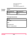
LED indicators
Description
Each clip-on-housing for a radio, digital cellular phones or Bluetooth communication
has Light Emitting Diode indicators on the bottom side. They indicate the basic
device status.
Diagram
a
b
c
d
GPS12_089
Operation
RX1200
a) Warning LED, available for Satelline
3AS
b) Data transfer LED
c) Signal strength LED or Status LED
for Bluetooth communication
d) Power LED
89
RX1200
Operation
90
Description of the LED’s
IF the
on
is
THEN
Warning
LED
GFU14 with
Satelline 3AS
red
the device is in the configuration
mode controlled from the PC via
cable.
Data
transfer
LED
any device
off
data is not being transferred.
green or flashing
green
data is being transferred.
IF the
on
is
THEN
Signal
strength
LED
GFU19 (US),
GFU25 (CAN)
with CDMA
MultiTech
MTMMC-C
red
device is on, not registered on
the network.
flashing red
device is on, registered on the
network.
off
GFU17 with
red
Siemens MC45
red: long flash,
short break
Operation
download mode or device is off.
call is in progress.
no SIM card inserted, no PIN
entered or network search, user
authentication or network login in
progress.
red: short flash,
long break
logged onto network, no call in
progress.
off
device is off.
RX1200
91
RX1200
Operation
IF the
on
is
92
THEN
GFU24 with
red
call is in progress.
Siemens MC75
red: long flash, long no SIM card inserted, no PIN
break
entered or network search, user
authentication or network login in
progress.
GFU15 with
Pacific Crest
PDL
red: short flash,
long break
logged onto network, no call in
progress.
red: flashing red,
long break
GPRS PDP context activated.
red: long flash,
short break
Packet switched data transfer is
in progress.
off
device is off.
red or flashing red
the communication link, Data
Carrier Detection, is okay on the
roving receiver.
off
the DCD is not okay.
IF the
Status
LED
on
is
THEN
GFU14 with
Satelline 3AS
red or flashing red
the communication link, Data
Carrier Detection, is okay on the
roving receiver.
off
the DCD is not okay.
Bluetooth
green
communication
orange
purple
Power
LED
Operation
any device
Bluetooth is in stand-by mode.
Bluetooth is in configuration
mode.
Bluetooth is connecting.
blue
Bluetooth has connected.
off
power is off.
green
power is okay.
RX1200
93
RX1200
Operation
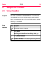
4.7
94
Basic Operation
Turning RX1200 on
Type
Description
PROG (ON)
When RX1200 has a power supply, pressing PROG (ON)
on RX1200 unit switches the unit on.
Connection to
the LEMO port
When RX1200 is connected via cable to either TPS1200 or
GPS1200 that are already switched on, RX1200 automatically switches on.
)
Connection to
the clip-on connector
RX1200 has to be connected to a power source
to switch on automatically. This can be either an
external battery connected with a Y-cable, power
received from GPS1200 or an internal battery for
RX1220/RX1250.
When RX1200 is connected to the clip-on connector of
GPS1200 that is already on, RX1200 automatically
switches on.
When RX1200 has been turned on
Operation
Type
Description
Connected to
GPS1200
•
When RX1200 is operating with the GPS1200, RX1200
acts as the control unit of the GPS1200.
Direct connection to
TPS1200
•
When RX1200 is connected directly to TPS1200 with a
cable, RX1200 acts as a secondary control unit for
TPS1200 which additionally offers dedicated alpha
keyboard and touch screen capabilities.
Radio connection to
TPS1200
•
When RX1220 is connected to TPS1200 via the radio
link, RX1220 acts as a remote control system enabling
operation of TPS1200 from the prism pole.
Operating
•
without an instrument
When RX1210/RX1220 is activated without a connection to either TPS1200 or GPS1200, it will enter the
local mode.
•
When RX1250 is activated without a connection to
SmartAntenna or GPS1200, survey independent tasks
such as COGO can still be performed.
RX1200
95
RX1200
Operation
Turning RX1200 off
Type
Description
OFF
The RX1200 can only be turned off in the Main Menu
screen.
•
96
For RX1210/RX1220:
Pressing the USER and PROG keys simultaneously
will switch off RX1200.
OR
Hold ESC for 2 s.
•
For RX1250:
SHIFT OFF (F2) to completely turn off.
Unplugging
or unclipping
from the instrument
Disconnecting either the LEMO cable or the clip-on
connector of RX1200 without an internal battery automatically switches it off.
Auto power down
Option to set shutdown and sleep events after user defined
duration of instrument inactivity when working with TPS
instruments.
Sleep mode on
RX1250
Description
In sleep mode, the RX1250 shuts down and reduces power. The sleep mode is
designed to preserve energy. Rebooting RX1250 from sleep mode is quicker than a
cold start after turning off.
Putting RX1250 into sleep mode
The RX1250 can only be put into sleep mode in the Main Menu screen.
Press the USER and PROG keys simultaneously.
OR
Press SHIFT SLEEP (F3).
OR
Hold ESC for 2 s.
Lock/Unlock
keyboard
Option Description
Lock
To lock the keyboard press and hold SHIFT for 3 s. The message
’Keyboard locked’ is momentariliy displayed on the Message Line.
Unlock To unlock the keyboard press and hold SHIFT for 3 s. The message
’Keyboard unlocked’ is momentariliy displayed on the Message Line.
Operation
RX1200
97
RX1200
Operation
Switching between
Leica software and
Windows CE
desktop
98
a
b
d
a) Icon to start Leica
software
b) Windows CE desktop
c) Task bar
d) Start button
c
RX12_33
Access Leica software
IF
THEN
RX1250 is started
the Leica software starts up automatically.
IF
THEN
Windows CE
desktop is active
double click
OR
SHIFT PROG (
Leica software is
minimised
to display the Leica software.
) to display the Leica software.
double click
to maximise it.
OR
select SmartRover in the task bar to maximise it.
Access Windows CE desktop
IF
THEN
Leica software is to be minimised
SHIFT MINIM (F5) in Main Menu.
Leica software is to be closed
SHIFT EXIT (F6) in Main Menu.
Windows CE task bar is to be displayed SHIFT PROG (
Operation
RX1200
).
99
RX1200
Operation
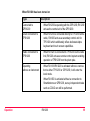
4.8
100
Licence Keys
Description
A licence key can be used to activate application programs and protected options
and can be used to define the expiry date of the software maintenance.
A licence key is required for:
Application programs
Protected options
•
COGO Area Division
•
GPS Survey functionality on RX1250
•
DTM Stakeout
•
Some OWI messages
•
Reference Plane
•
GLONASS option
•
Reference Line
•
RoadRunner
•
Survey Cross Section
•
Volume Calculations
A licence key file can be uploaded to the receiver/RX1250. To upload a licence key
file the file should be located on the \SYSTEM directory of the CompactFlash card.
Licence key files use the naming convention L_123456.key, where 123456 is the
instrument serial number.
Licence keys can also be typed in manually in Main Menu: Tools...\Licence Keys
or the first time the application program is started.
Access
Select Main Menu: Tools...\Licence Keys.
OR
Select an application program on RX1250 not yet activated.
TOOLS
Enter Licence Key
CONT (F1)
To accept changes and return to
GPS1200 Main Menu or continue
with application program.
SHIFT DEL (F4)
To delete all licence keys on the
receiver/RX1250.
Operation
RX1200
101
RX1200
Operation
102
Description of fields
Field
Option
<Method:>
Description
The method used to input the licence key to activate the application program or the protected
options or the software maintenance.
Upload Key File The licence key file is uploaded from the
CompactFlash card. The licence key file must
be stored in the \SYSTEM directory on the
CompactFlash card.
Manual Entry of Allows the licence key to be typed in manually.
Key
<Key:>
User input
Available for <Method: Manual Entry of Key>.
The licence key required to activate an application program. Entry is not case sensitive.
Next step
CONT (F1) returns to GPS1200 Main Menu or continues with selected application
program.
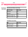
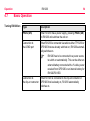
4.9
Guidelines for Correct Results with GNSS Surveys
Undisturbed satellite signal reception
Successful GNSS surveys require undisturbed satellite signal reception, especially
at the receiver which serves as a reference. Set up the receivers in locations which
are free of obstructions such as trees, buildings or mountains.
Steady antenna for
static surveys
For static surveys, the antenna must be kept perfectly steady throughout the whole
occupation of a point. Put the antenna on a tripod or pillar.
Centred and
levelled antenna
Centre and level the antenna precisely over the marker.
Operation
RX1200
103
RX1200
Operation
4.10
RX1250 Connections
4.10.1
Connection to SmartAntenna
Via Bluetooth
step-by-step
Step
1.
Description
Select Main Menu: Config...\Interfaces... in the Leica software.
2.
Highlight SmartAntenna.
3.
EDIT (F3)
4.
CONFIGURE SmartAntenna Interface
<Use Device: Yes>
Select a free Bluetooth port.
5.
DEVCE (F5)
6.
CONFIGURE Devices
Highlight ATX1230.
7.
CONT (F1)
8.
SRCH (F4) to search for Bluetooth devices.
)
SmartAntenna must be turned on.
104
Step
9.
Description
CONFIGURE Search Bluetooth Device
All available Bluetooth devices are displayed.
10.
Highlight the SmartAntenna to be used.
11.
CONT (F1)
)
)
Operation
If the SmartAntenna selected is connected for the first time, a Windows
CE authentication request comes up. Type in 0000 as identification
number for Leica’s Bluetooth and click OK.
Once the Bluetooth connection is established, the Bluetooth LED on the
SmartAntenna starts flashing in blue.
RX1200
105
RX1200
Operation
4.10.2
106
Connection to a Digital Cellular Phone
Via Bluetooth
step-by-step
Step
Description
1.
Select Main Menu: Config...\Interfaces... in the Leica software.
2.
Highlight Real-Time.
3.
EDIT (F3)
4.
CONFIGURE Real-Time Mode
<R-Time Mode: Rover> or <R-Time Mode: Reference>
Select a free Bluetooth port.
5.
DEVCE (F5)
6.
CONFIGURE Devices, Modems/GSM page
Highlight a Bluetooth capable digital cellular phone.
7.
CONT (F1)
8.
SRCH (F4) to search for the digital cellular phone.
)
9.
The digital cellular phone must be turned on and Bluetooth must be activated.
CONFIGURE Search Bluetooth Device
Step
Description
All available Bluetooth devices are displayed.
10.
Highlight the digital cellular phone to be used.
11.
CONT (F1)
)
)
)
Operation
If the digital cellular phone selected is connected for the first time, the
Windows CE dialog for pairing comes up. Type in 0000 as identification
number for Leica’s Bluetooth and click OK.
Some digital cellular phones also ask for the identification number for
Leica’s Bluetooth. The number is 0000.
Some digital cellular phones also ask for an acknowledgement before
connecting to another Bluetooth device.
RX1200
107
RX1200
Operation
4.10.3
108
Connection to a Personal Computer
ActiveSync
Connect USB cable
to PC for the first
time
step-by-step
Microsoft ActiveSync is the synchronization software for Windows mobile-based
pocket PC’s. ActiveSync enables a PC and a Windows mobile-based pocket PC, like
the RX1250, to communicate.
ActiveSync is freeware. It can be downloaded from the Microsoft website.
Step
Description
1.
Start the PC.
2.
Have the GPS1200 firmware CD version 4.0 or higher ready.
3.
Plug the GEV161 cable into RX1250.
4.
Turn the RX1250 on.
5.
Wait until the Windows CE desktop is visible.
6.
)
Plug the GEV161 cable into the USB port of the PC.
The new hardware wizard starts up automatically.
7.
Tick No, not at this time.
8.
Next>.
9.
Tick Install from a list or specific location (Advanced).
Step
Description
10.
Next>.
11.
Insert the GPS1200 firmware CD version 4.0 or higher.
12.
Tick Search removable media (floppy, CD-ROM...).
13.
Next>.
14.
Confirm Hardware Installation window with Continue Anyway.
15.
Finish.
16.
Run the ActiveSync installation program if not already installed.
17.
Allow USB connections inside the Connection Settings window of
ActiveSync.
18.
Is LGO used?
If yes, continue with step 6. in paragraph "Connect to LGO via USB cable
step-by-step".
Is no, continue with step 6. in paragraph "Connect to PC via USB cable
step-by-step".
Operation
RX1200
109
RX1200
Operation
Connect to LGO via
USB cable
step-by-step
Step
Description
1.
Start the PC.
2.
Plug the GEV161 cable into RX1250.
3.
Turn the RX1250 on.
4.
Plug the GEV161 cable into the USB port of the PC.
)
ActiveSync starts up automatically.
If does not start automatically, start ActiveSync.
If not already installed, run the ActiveSync installation program.
5.
Allow USB connections inside the Connection Settings window of
ActiveSync.
6.
Start LGO or install it if not available.
7.
Start the Leica SmartRover software on the RX1250.
8.
Goto Data Exchange Manager in LGO.
9.
Click Refresh on the ActiveSync folder.
10.
)
110
Establish the communication to RX1250.
The folders CF-Card, System1200 and Sensor System are displayed in
the Data Exchange Manager.
Connect to PC via
USB cable
step-by-step
Step
Description
1.
Start the PC.
2.
Plug the GEV161 cable into RX1250.
3.
Turn the RX1250 on.
4.
Plug the GEV161 cable into the USB port of the PC.
)
5.
6.
)
Operation
ActiveSync starts up automatically.
If does not start automatically, start ActiveSync.
If not already installed, run the ActiveSync installation program.
Allow USB connections inside the Connection Settings window of
ActiveSync.
Click on Explore in ActiveySync.
The folders on the RX1250 are displayed under Mobile Devices.
The folders of the CompactFlash can be found in StorageCard.
RX1200
111
RX1200
Operation
Via Bluetooth
step-by-step
Step
1.
112
Description
Activate Bluetooth on the PC.
The steps required depend on the Bluetooth driver and other PC specific
configurations. On the PC, always ensure that
•
the correct COM port is defined.
•
the COM port is configured as incoming, which allows Bluetooth
devices to detect the PC.
2.
Turn the RX1250 on.
3.
Go to Start/Settings/Control Panel/Bluetooth Device.
4.
Click Scan Device.
5.
Highlight the service required in the Untrusted box.
6.
Click - -> to move the service to the Trusted box.
7.
Highlight the service required in the Trusted box.
8.
Right mouse click to access the context menu.
9.
Tick Active.
)
Go to Start/Settings/Control/System/Device Name to give the RX1250
a specific name.
Step
Description
10.
Go to Start/Settings/Control Panel/PC Connection.
11.
Select Bluetooth from the combo box.
12.
Go to Start/Programs/Communication/ActiveSync to initialise the
communication.
)
13.
Start LGO or install it if not available.
14.
Goto Data Exchange Manager in LGO.
15.
Click Refresh on the ActiveSync folder.
16.
Establish the communication to RX1250.
)
Operation
As soon as the communication is initialised on the RX1250, ActiveSync
establishes the link between the PC and RX1250.
The folders CF-Card, System1200 and Sensor System are displayed in
the Data Exchange Manager.
RX1200
113
RX1200
Operation
4.11
Working with the TPS Instrument
4.11.1
Working in Remote Mode
Description
Access
step-by-step
114
In the remote mode TPS1200 is controlled from RX1220. To work in this mode
TPS1200 must be set to RCS mode. Refer to "TPS1200 Technical Reference
Manual" for more information. While in RCS mode TPS1200 can still be controlled
with the keys on the instrument.
Step
)
Description
Proceed to the local menu of RX1200.
1.
Select RX1200:
Main Configuration Menu: Radio/Comms Settings, Modes page.
2.
Set <ComMode: RCS Mode>.
)
<ComMode: RCS Mode> is set automatically when turning on RX1220.
4.11.2
Working in Transparent Mode
Description
Access
step-by-step
Operation
<ComMode: Transparent> enables the remote control of TPS1200 with GeoCOM
commands. RX1220 becomes a transparent radio modem, like the RadioHandle or
TCPS27B. GeoCOM commands can be sent from a computer to RX1220, which are
then sent to TPS1200 via RadioHandle or TCPS27B. These commands will be
executed on TPS1200 and results can be sent back.
Step
)
)
Description
From CONFIGURE Interfaces on TPS1200 ensure that GeoCOM Mode
is turned on and RCS Mode is turned off.
Proceed to the local menu of RX1200.
1.
Select RX1200:
Main Configuration Menu: Radio/Comms Settings, Modes page.
2.
Set <ComMode: Transparent>.
RX1200
115
RX1200
Operation
4.11.3
116
Working in Semi-Transparent Mode
Description
)
Access
step-by-step
<ComMode: Semi-Transparent> enables the total remote control of TPS1200 in
RCS mode but the data being captured by TPS1200 will be sent via radio link to the
LEMO port of RX1200. A computer connected to this port will receive the data
captured on TPS1200 in real-time.
Data being sent over the radio link in this mode is not protected by a Leica protocol.
There exists a chance of data loss without notification.
Step
)
)
Description
From CONFIGURE Interfaces on TPS1200 ensure that GSI Output and
RCS Mode are turned on.
Proceed to the local menu of RX1200.
1.
Select RX1200:
Main Configuration Menu: Radio/Comms Settings, Modes page.
2.
Set <ComMode: Semi-Transparent>.
Operation
RX1200
117
RX1200
Local Mode
5
5.1
)
118
Local Mode
Accessing the Main Configuration Menu
This option is available for RX1250 in terminal mode.
Access
Press USER for 2 s.
OR
Automatically after 10 s when no sensor can be detected.
RX1200
A message is displayed for a period of 10 s.
Next step
IF RX1200
THEN
is to be configured
CONF (F2) leads directly to RX1200 Main Configuration Menu.
is to be connected automati- AUTO (F3) initiates the auto detect function.
cally
RX1200 tries to connect to any available instrument
or receiver.
Local Mode
IF RX1200
THEN
is to be connected to TPS
TPS (F4) tries to connect to any available TPS
instrument.
is to be connected to GPS
GPS (F5) tries to connect to any available GPS
receiver.
RX1200
119
RX1200
Local Mode
5.2
120
Overview of the Main Configuration Menu
RX1200
Main
Configuration
Menu
Description of main menu functions
Main menu function Description
Refer to
chapter
Choose Sensor
Select the sensor to be working with RX1200.
5.3
Local Settings
Change or adjust the display and sound
settings of RX1200.
5.4
Radio/Comms
Settings
Change or adjust the communication settings of 5.5
RX1200.
Work with Sensor
Leave the Local Mode and work with the
selected sensor.
5.6
Next step
CONT (F1) selects the highlighted option and continues with the next screen.
5.3
Choosing a Sensor
Access
step-by-step
Step
Description
1.
Refer to "5.1 Accessing the Main Configuration Menu" to access RX1200
Main Configuration Menu.
2.
RX1200 Main Configuration Menu
Highlight Choose Sensor.
3.
RX1200
Choose Sensor
Local Mode
CONT (F1).
Description of fields
Field
Option
Description
Sensor
TPS1200
Sets RX1200 to work with TPS1200. Choose
this option if working only TPS1200.
GPS1200
Sets RX1200 to work with GPS1200. Choose
this option if working only GPS1200.
Auto Detect
Sets RX1200 to try and connect with any
connected instrument when starting up. This is
the default setting.
RX1200
121
Local Mode
RX1200
Next step
CONT (F1) to return to RX1200 Main Configuration Menu.
122
5.4
Local Settings
Description
Access
step-by-step
The settings on this screen allow the screen appearance to be configured, turn the
notification beeps on and off and define the behaviour of the keys. The settings are
stored on RX1200 itself.
Step
Description
1.
Refer to "5.1 Accessing the Main Configuration Menu" to access RX1200
Main Configuration Menu.
2.
RX1200 Main Configuration Menu
Highlight Local Settings.
3.
RX1200
Local Settings,
Display page
Local Mode
CONT (F1).
Description of fields
Field
Option
Description
<Touch Screen:>
On or Off
Turns touch screen on and off.
<Screen Beep:>
Off, Soft or Loud
Controls the beep upon touching the
touch screen.
RX1200
123
RX1200
Local Mode
124
Field
Option
Description
<Screen Illum:>
Off, Always On,
On for 30 s,
On for 1 min,
On for 2 min or
On for 5 min
Controls the screen illumination to be on,
off or on for the specified time after the
last key was pressed or touch screen
event.
<Key Illum:>
Off, Always On, or Controls the keyboard illumination.
Same as Screen
<Contrast:>
From
0% to 100%
Adjust the contrast level for the display
using the arrow keys or using the stylus
on the slider.
<Heating:>
Off
The screen heating never comes on.
Automatic
The screen heating comes on automatically at 5°C and below and shuts off
again at 7°C.
Next step
IF
THEN
the local settings are to be exited
CONT (F1) accepts changes and returns to the
screen from where this screen was accessed.
the touch screen is to be calibrated CALIB (F5) calibrates the touch screen.
the next page is to be accessed
RX1200
Local Settings,
Beeps page
PAGE (F6) changes to another page on this
screen
Description of fields
Field
Option
Description
<Warning Beeps:>
Off, Soft or
Loud
Controls the beep for acoustic warning
signals.
<Key Beeps:>
Off, Soft or
Loud
Controls the beep upon key presses on
RX1200.
Next step
PAGE (F6) changes to the More page.
Local Mode
RX1200
125
RX1200
Local Mode
RX1200
Local Settings,
More page
126
Description of fields
Field
Option
Description
<Language:> Choicelist
Allows the local mode functions to be displayed
in different languages. The language setting
does not affect the language displayed when
working with a sensor. When working with a
sensor, the language selected in the sensor is
shown on RX1200.
<Action:>
None
RX1200 does not switch off automatically.
RX Off
After the preset time of RX1200 inactivity,
RX1200 switches off.
RX+TPS Off
After the preset time of RX1200 inactivity, both
RX1200 and TPS1200 switch off.
<After time:> From 1 to 99
minutes
Time of RX1200 inactivity before the set action
is executed.
Next step
CONT (F1) to return to the screen from where this screen was accessed.
5.5
Radio Settings
5.5.1
Radio Communication Settings
Description
Access
step-by-step
Allows changes to the communication parameters of RX1200. This screen is more
relevant to RX1220. For RX1210, this screen is relevant when combined with
TCPS27R.
Step
Description
1.
Refer to "5.1 Accessing the Main Configuration Menu" to access RX1200
Main Configuration Menu
2.
RX1200 Main Configuration Menu
Highlight Radio/Comms Settings.
3.
RX1200
Radio/Comms
Settings,
Modes page
Local Mode
CONT (F1).
Description of fields
Field
Option
Description
<ComMode:> RCS Mode
RX1200
RX1200 operates as a secondary control unit for
TPS1200.This is the default setting of RX1200.
127
RX1200
Local Mode
Field
<Modem:>
128
Option
Description
Transparent
Deactivates the software functionality of
RX1220, converting it into a radio modem which
can be used with RadioHandle or TCPS27B to
communicate remotely with TPS1200. Refer to
"4.11.2 Working in Transparent Mode" for more
information.
SemiTransparent
Enables measurement data to be sent from
TPS1200, via the radio link, to the LEMO port of
RX1200 in real-time. RX1200 continues to
control TPS1200 in the normal RCS way. Refer
to "4.11.3 Working in Semi-Transparent Mode"
for more information.
Output
Communication internally via the radio modem
or externally via the LEMO port.
<Baud Rate:> From 19200
to 115200
This field is only available when:
<ComMode: Transparent> or
<ComMode: Semi-Transparent>.
Next step
RX1200
Radio/Comms
Settings,
Param page
Local Mode
IF
THEN
the local settings
are to be exited
CONT (F1) accepts changes and returns to the screen from
where this screen was accessed.
the next page is to
be accessed
PAGE (F6) changes to another page on this screen
Description of fields
Field
Option
Description
<Link Number:>
From 0 to
15
Assigned channel number enabling multiple
pairs of radios to work simultaneously in the
same area without interfering with each
other.The link number for RadioHandle or
TCPS27 and RX1220 must be the same.
<Baud Rate:>
Output
Frequency of data transfer from instrument to
device.
<Parity:>
Output
Error checksum at the end of a block of digital
data.
RX1200
129
RX1200
Local Mode
130
Field
Option
Description
<Terminator:>
Output
The terminator of a data packet.
<Data Bits:>
Output
Number of bits in a block of digital data.
<Stop Bits:>
Output
Number of bits to end a block of digital data.
<Set as:>
Remote
Sets the internal radio into a remote mode. The
radio modules inside RadioHandle or TCPS27
and RX1220 must be set to opposite settings. It
is recommended to set RX1220 to remote and
TCPS27 to base.
Base
Sets the internal radio into a base mode
Next step
IF
THEN
the local settings
are to be exited
CONT (F1) accepts changes and returns to the screen from
where this screen was accessed.
default values are
to be restored
DEFLT (F3) restores Leica default values to the internal
modem of RX1220.
IF
THEN
radio settings are to EXT R (F4) displays and allows editing of TCPS27 external
be edited
radio settings when connected to the LEMO port.
radio settings are to SYNC (F5) synchronises the settings between the internal
be synchronised
radio of RX1220 and external radio TCPS27B when
connected to each other via cable.
Open RX1200 Radio/Comms Settings, Param
page to change the parameters for the communication between RX1220 and TCPS27.
)
the next page is to
be accessed
Local Mode
PAGE (F6) changes to another page on this screen
RX1200
131
RX1200
Local Mode
5.5.2
132
Configuring the Radios
Description
View/edit
internal/external
radio settings
step-by-step
RX1200 allows the configuration of
• it's internal radio RX1220.
•
the external radio TCPS27.
•
the simultaneous synchronisation of both radios.
Step
Description
1.
Open RX1200 Radio/Comms Settings, Param page.
2.
•
For RX1220 the internal radio settings are displayed.
•
For RX1210 the external radio settings are displayed.
)
)
3.
DEFLT (F3) to reset to Leica default values
Edit settings.
EXT R (F4) to view the external radio settings when TCPS27 is connected
to RX1220.
4.
CONT (F1) to exit and accept changes.
5.
ESC to exit and disregard changes.
Synchronising
radio settings for
RX1220
step-by-step
Local Mode
Step
Description
1.
Connect TCPS27 to RX1220 with a Y-cable and external battery.
2.
Open RX1200 Radio/Comms Settings, Param page.
3.
SYNC (F5).
4.
Open RX1200 Radio/Comms Settings, Param page.
5.
The settings of the internal radio of RX1220 are displayed.
6.
Edit settings.
RX1200
133
RX1200
Local Mode
5.6
134
Working with a Sensor
Description
Exit Configuring
RX1200
step-by-step
This function allows to leave the RX1200 Main Configuration Menu and returns to
working with the sensor.
Step
Description
1.
From any screen in the local mode press SHIFT QUIT (F6).
OR
ESC until RX1200 Main Configuration Menu is displayed.
2.
RX1200 Main Configuration Menu
Highlight Work with Sensor.
3.
CONT (F1).
Local Mode
RX1200
135
RX1200
Care and Transport
6
6.1
136
Care and Transport
Transport
Transport in a road
vehicle
Never carry the product loose in a road vehicle, as it can be affected by shock and
vibration. Always carry the product in its transport container and secure it.
Shipping
When transporting the product by rail, air or sea, always use the complete original
Leica Geosystems packaging, transport container and cardboard box, or its equivalent, to protect against shock and vibration.
Shipping, transport
of batteries
When transporting or shipping batteries, the person in charge of the product must
ensure that the applicable national and international rules and regulations are
observed. Before transportation or shipping, contact your local passenger or freight
transport company.
6.2
Storage
Product
Respect the temperature limits when storing the equipment, particularly in summer
if the equipment is inside a vehicle. Refer to "9 Technical Data" for information about
temperature limits.
Li-Ion batteries
•
Refer to "9 Technical Data" for information about storage temperature range.
•
A storage temperature range of -20 to +30°C/-4 to 68°F in a dry environment is
recommended to minimise self-discharging of the battery.
•
At the recommended storage temperature range, batteries containing a 10% to
50% charge can be stored for up to one year. After this storage period the
batteries must be recharged.
•
Remove batteries from the product and the charger before storing.
Care and Transport
•
After storage recharge batteries before using.
•
Protect batteries from damp and wetness. Wet or damp batteries must be dried
before storing or use.
RX1200
137
RX1200
Care and Transport
6.3
138
Cleaning and Drying
Product
Use only a clean, soft, lint-free cloth for cleaning. If necessary, moisten the cloth with
water or pure alcohol. Do not use other liquids; these may attack the polymer components.
Damp products
Dry the product, the transport container, the foam inserts and the accessories at a
temperature not greater than 40°C / 108°F and clean them. Do not repack until
everything is completely dry.
Cables and plugs
Keep plugs clean and dry. Blow away any dirt lodged in the plugs of the connecting
cables.
Care and Transport
RX1200
139
RX1200
Safety Directions
7
7.1
140
Safety Directions
General Introduction
Description
The following directions should enable the person responsible for the product, and
the person who actually uses the equipment, to anticipate and avoid operational
hazards.
The person responsible for the product must ensure that all users understand these
directions and adhere to them.
7.2
Intended Use
Permitted use
Adverse use
Safety Directions
•
Remote control of surveying products.
•
Data transmission to external appliances.
•
Transmitting and receiving data.
•
Use of the product without instruction.
•
Use outside of the intended limits.
•
Disabling safety systems.
•
Removal of hazard notices.
•
Opening the product using tools, for example screwdriver, unless this is specifically permitted for certain functions.
•
Modification or conversion of the product.
•
Use after misappropriation.
•
Use of products with obviously recognizable damages or defects.
•
Use with accessories from other manufacturers without the prior explicit
approval of Leica Geosystems.
•
Inadequate safeguards at the surveying site, for example when measuring on
roads.
RX1200
141
RX1200
Safety Directions
•
Warning
142
Controlling of machines, moving objects or similar monitoring application without
additional control- and safety installations.
Adverse use can lead to injury, malfunction and damage.
It is the task of the person responsible for the equipment to inform the user about
hazards and how to counteract them. The product is not to be operated until the user
has been instructed on how to work with it.
7.3
Limits of Use
Environment
Suitable for use in an atmosphere appropriate for permanent human habitation: not
suitable for use in aggressive or explosive environments.
Danger
Local safety authorities and safety experts must be contacted before working in
hazardous areas, or in close proximity to electrical installations or similar situations
by the person in charge of the product.
Safety Directions
RX1200
143
RX1200
Safety Directions
7.4
144
Responsibilities
Manufacturer of the
product
Leica Geosystems AG, CH-9435 Heerbrugg, hereinafter referred to as Leica
Geosystems, is responsible for supplying the product, including the user manual and
original accessories, in a completely safe condition.
Manufacturers of
non
Leica Geosystems
accessories
The manufacturers of non Leica Geosystems accessories for the product are
responsible for developing, implementing and communicating safety concepts for
their products, and are also responsible for the effectiveness of those safety
concepts in combination with the Leica Geosystems product.
Person in charge of
the product
The person in charge of the product has the following duties:
• To understand the safety instructions on the product and the instructions in the
user manual.
•
To be familiar with local regulations relating to safety and accident prevention.
•
To inform Leica Geosystems immediately if the product and the application
becomes unsafe.
•
To ensure that the national laws, regulations and conditions for the operation of
radio transmitters are respected. Not applicable for RX1210.
Warning
Safety Directions
The person responsible for the product must ensure that it is used in accordance
with the instructions. This person is also accountable for the training and the deployment of personnel who use the product and for the safety of the equipment in use.
RX1200
145
Safety Directions
7.5
RX1200
146
International Warranty, Software Licence Agreement
International
Warranty
The International Warranty can be downloaded from the Leica Geosystems home
page at http://www.leica-geosystems.com/internationalwarranty or received from
your Leica Geosystems dealer.
Software Licence
Agreement
This product contains software that is preinstalled on the product, or that is supplied
to you on a data carrier medium, or that can be downloaded by you online pursuant
to prior authorization from Leica Geosystems. Such software is protected by copyright and other laws and its use is defined and regulated by the Leica Geosystems
Software Licence Agreement, which covers aspects such as, but not limited to,
Scope of the Licence, Warranty, Intellectual Property Rights, Limitation of Liability,
Exclusion of other Assurances, Governing Law and Place of Jurisdiction. Please
make sure, that at any time you fully comply with the terms and conditions of the
Leica Geosystems Software Licence Agreement.
Such agreement is provided together with all products and can also be found at the
Leica Geosystems home page at http://www.leica-geosystems.com/swlicense
or your Leica Geosystems dealer.
You must not install or use the software unless you have read and accepted the
terms and conditions of the Leica Geosystems Software Licence Agreement. Instal-
lation or use of the software or any part thereof, is deemed to be an acceptance of
all the terms and conditions of such licence agreement. If you do not agree to all or
some of the terms of such licence agreement, you may not download, install or use
the software and you must return the unused software together with its accompanying documentation and the purchase receipt to the dealer from whom you
purchased the product within ten (10) days of purchase to obtain a full refund of the
purchase price.
Safety Directions
RX1200
147
RX1200
Safety Directions
7.6
148
End User Licence Agreement EULA
EULA terms
•
You have acquired a device RX1250 that includes software licenced by Leica
Geosystems from an affiliate of Microsoft Corporation ("MS"). Those installed
software products of MS origin, as well as associated media, printed materials,
and "online" or electronic documentation ("SOFTWARE") are protected by international intellectual property laws and treaties. The SOFTWARE is licenced, not
sold. All rights reserved.
•
IF YOU DO NOT AGREE TO THIS END USER LICENCE AGREEMENT
("EULA"), DO NOT USE THE DEVICE OR COPY THE SOFTWARE, INSTEAD,
PROMPTLY CONTACT Leica Geosystems FOR INSTRUCTIONS ON
RETURN OF THE UNUSED DEVICE(S) FOR A REFUND. ANY USE OF THE
SOFTWARE, INCLUDING BUT NOT LIMITED TO USE ON THE DEVICE,
WILL CONSTITUTE YOUR AGREEMENT TO THIS EULA (OR RATIFICATION OF ANY PREVIOUS CONSENT).
•
GRANT OF SOFTWARE LICENCE. This EULA grants you the following
licence:
• You may use the SOFTWARE only on the DEVICE.
• NOT FAULT TOLERANT. THE SOFTWARE IS NOT FAULT TOLERANT.
Leica Geosystems HAS INDEPENDENTLY DETERMINED HOW TO USE
THE SOFTWARE IN THE DEVICE, AND MS HAS RELIED UPON Leica
Geosystems TO CONDUCT SUFFICIENT TESTING TO DETERMINE THAT
THE SOFTWARE IS SUITABLE FOR SUCH USE.
• NO WARRANTIES FOR THE SOFTWARE. THE SOFTWARE is provided
"AS IS" and with all faults. THE ENTIRE RISK AS TO SATISFACTORY
QUALITY, PERFORMNCE, ACCURACY, AND EFFORT (INCLUDING LACK
OF NEGLIGENCE) IS WITH YOU. ALSO, THERE IS NO WARRANTY
AGAINST INTERFERENCE WITH YOUR ENJOYMENT OF THE SOFTWARE OF AGAINST INFRINGEMENT. IF YOU HAVE RECEIVED ANY
WARRANTIES REGARDING THE DEVICE OR THE SOFTWARE, THOSE
WARRANTIES DO NOT ORIGINATE FROM, AND ARE NOT BINDING ON,
MS.
• No Liability for Certain Damages. EXCEPT AS PROHIBITED BY LAW, MS
SHALL HAVE NO LIABILITY FOR ANY INDIRECT, SPECIAL, CONSEQUENTIAL OR INCIDENTAL DAMAGES ARISING FROM OR IN CONNECTION WITH THE USE OR PERFORMANCE OF THE SOFTWARE. THIS
LIMITATION SHALL APPLY EVEN IF ANY REMEDY FAILS FOF ITS
ESSENTIAL PURPOSE. IN NO EVENT SHALL MS BE LIABLE FOR ANY
AMOUNT IN EXCESS OF U.S. TWO HUNDRED FIFTY DOLLARS
(U.S.$250.00).
• Limitations on Reverse Engineering, Decompilation, and Disassembly.
You may not reverse engineer, decompile, or disassemble the SOFTWARE,
Safety Directions
RX1200
149
Safety Directions
RX1200
150
except and only to the extent that such activity is expressly permitted by applicable law notwithstanding thes limitation.
• SOFTWARE TRANSFER ALLOWED BUT WITH RESTRICTIONS. You may
permanently transfer rights under this EULA only as part of a permanent sale
or transfer of the Device, and only if the recipient agrees to this EULA. If the
SOFTWARE is an upgrade, any transfer must also include all prior versions
of the SOFTWARE.
• EXPORT RESTRICTIONS. You acknowledge that SOFTWARE is subject to
U.S. and European Union export jurisdiction. You agree to comply with all
applicable international and national laws that apply to the SOFTWARE,
including the U.S. Export Administration Regulations, as well as end-user,
end-use and destination restrictions issued by U.S. and other governments.
For additional information see http://www.microsoft.com/exporting/.
7.7
Hazards of Use
Warning
The absence of instruction, or the inadequate imparting of instruction, can lead to
incorrect or adverse use, and can give rise to accidents with far-reaching human,
material, financial and environmental consequences.
Precautions:
All users must follow the safety directions given by the manufacturer and the directions of the person responsible for the product.
Danger
Because of the risk of electrocution, it is very dangerous to use poles and extensions
in the vicinity of electrical installations such as power cables or electrical railways.
Precautions:
Keep at a safe distance from electrical installations. If it is essential to work in this
environment, first contact the safety authorities responsible for the electrical installations and follow their instructions.
Safety Directions
RX1200
151
Safety Directions
RX1200
152
Warning
By surveying during a thunderstorm you are at risk from lightning.
Precautions:
Do not carry out field surveys during thunderstorms.
Warning
During dynamic applications, for example stakeout procedures there is a danger of
accidents occurring if the user does not pay attention to the environmental conditions
around, for example obstacles, excavations or traffic.
Precautions:
The person responsible for the product must make all users fully aware of the
existing dangers.
Warning
Inadequate securing of the surveying site can lead to dangerous situations, for
example in traffic, on building sites, and at industrial installations.
Precautions:
Always ensure that the survey site is adequately secured. Adhere to the regulations
governing safety and accident prevention and road traffic.
Caution
With the remote control on surveying products, it is possible that extraneous targets
will be picked out and measured.
Precautions:
When measuring in remote control mode, always check your results for plausibility.
Warning
Only Leica Geosystems authorized service workshops are entitled to repair these
products.
Warning
If computers intended for use indoors are used in the field there is a danger of electric shock.
Precautions:
Adhere to the instructions given by the computer manufacturer with regard to field
use in conjunction with Leica Geosystems products.
Caution
If the accessories used with the product are not properly secured and the product is
subjected to mechanical shock, for example blows or falling, the product may be
damaged or people may sustain injury.
Precautions:
When setting-up the product, make sure that the accessories, for example tripod,
tribrach, connecting cables, are correctly adapted, fitted, secured, and locked in
position.
Avoid subjecting the product to mechanical stress.
Safety Directions
RX1200
153
Safety Directions
RX1200
154
Caution
During the transport, shipping or disposal of batteries it is possible for inappropriate
mechanical influences to constitute a fire hazard.
Precautions:
Before shipping the product or disposing of it, discharge the batteries by running the
product until they are flat.
When transporting or shipping batteries, the person in charge of the product must
ensure that the applicable national and international rules and regulations are
observed. Before transportation or shipping contact your local passenger or freight
transport company.
Warning
Using a battery charger not recommended by Leica Geosystems can destroy the
batteries. This can cause fire or explosions.
Precautions:
Only use chargers recommended by Leica Geosystems to charge the batteries.
Warning
High mechanical stress, high ambient temperatures or immersion into fluids can
cause leackage, fire or explosions of the batteries.
Precautions:
Protect the batteries from mechanical influences and high ambient temperatures. Do
not drop or immerse batteries into fluids.
Warning
Short circuited battery terminals can overheat and cause injury or fire, for example
by storing or transporting in pockets if battery terminals come in contact with jewellery, keys, metallized paper or other metals.
Precautions:
Make sure that the battery terminals do not come into contact with metallic objects.
Warning
If the product is improperly disposed of, the following can happen:
• If polymer parts are burnt, poisonous gases are produced which may impair
health.
•
If batteries are damaged or are heated strongly, they can explode and cause
poisoning, burning, corrosion or environmental contamination.
•
By disposing of the product irresponsibly you may enable unauthorized persons
to use it in contravention of the regulations, exposing themselves and third
parties to the risk of severe injury and rendering the environment liable to
contamination.
Precautions:
The product must not be disposed with household waste.
Dispose of the product appropriately in accordance with the national
regulations in force in your country.
Always prevent access to the product by unauthorized personnel.
Safety Directions
RX1200
155
Safety Directions
RX1200
156
Product specific treatment and waste management information can be downloaded
from the Leica Geosystems home page at http://www.leica-geosystems.com/treatment or received from your Leica Geosystems dealer.
7.8
Electromagnetic Compatibility EMC
Description
The term Electromagnetic Compatability is taken to mean the capability of the
product to function smoothly in an environment where electromagnetic radiation and
electrostatic discharges are present, and without causing electromagnetic disturbances to other equipment.
Warning
Electromagnetic radiation can cause disturbances in other equipment.
Although the product meets the strict regulations and standards which are in force
in this respect, Leica Geosystems cannot completely exclude the possibility that
other equipment may be disturbed.
Caution
Safety Directions
There is a risk that disturbances may be caused in other equipment if the product is
used in conjunction with accessories from other manufacturers, for example field
computers, personal computers, two-way radios, non-standard cables or external
batteries.
Precautions:
Use only the equipment and accessories recommended by Leica Geosystems.
When combined with the product, they meet the strict requirements stipulated by the
guidelines and standards. When using computers and two-way radio, pay attention
to the information about electromagnetic compatibility provided by the manufacturer.
RX1200
157
Safety Directions
RX1200
158
Caution
Disturbances caused by electromagnetic radiation can result in erroneous measurements.
Although the product meets the strict regulations and standards which are in force
in this respect, Leica Geosystems cannot completely exclude the possibility that the
product may be disturbed by very intense electromagnetic radiation, for example,
near radio transmitters, two-way radios or diesel generators.
Precautions:
Check the plausibility of results obtained under these conditions.
Warning
If the product is operated with connecting cables attached at only one of their two
ends, for example external supply cables, interface cables, the permitted level of
electromagnetic radiation may be exceeded and the correct functioning of other
products may be impaired.
Precautions:
While the product is in use, connecting cables, for example product to external
battery, product to computer, must be connected at both ends.
Radios or digital
cellular phones
Warning
Safety Directions
Use of product with radio or digital cellular phone:
Electromagnetic radiation can cause disturbances in other equipment, in installations, in medical devices, for example pacemakers or hearing aids and in aircraft. It
can also affect humans and animals.
Precautions:
Although the product meets the strict regulations and standards which are in force
in this respect, Leica Geosystems cannot completely exclude the possibility that
other equipment may be disturbed or that humans or animals may be affected.
•
Do not operate the product in the vicinity of filling stations or chemical installations, or in other areas where an explosion hazard exists.
•
Do not operate the product near to medical equipment.
•
Do not operate the product in aircraft.
•
Do not operate the product for long periods immediately next to your body.
RX1200
159
RX1200
Safety Directions
7.9
160
FCC Statement, Applicable in U.S.
Applicablility
Warning
The grayed paragraph below is only applicable for RX1210 products without internal
radio.
This equipment has been tested and found to comply with the limits for a Class B
digital device, pursuant to part 15 of the FCC rules.
These limits are designed to provide reasonable protection against harmful interference in a residential installation.
This equipment generates, uses and can radiate radio frequency energy and, if not
installed and used in accordance with the instructions, may cause harmful interference to radio communication. However, there is no guarantee that interference will
not occur in a particular installation.
If this equipment does cause harmful interference to radio or television reception,
which can be determined by turning the equipment off and on, the user is encouraged to try to correct the interference by one or more of the following measures:
•
Reorient or relocate the receiving antenna.
•
Increase the separation between the equipment and the receiver.
•
Connect the equipment into an outlet on a circuit different from that to which the
receiver is connected.
•
Consult the dealer or an experienced radio/TV technician for help.
Warning
Labelling
RX1210
Changes or modifications not expressly approved by Leica Geosystems for compliance could void the user's authority to operate the equipment.
Type: RX1210 .......
.................
............
............
............
.................
.................
.................
.................
.................
This device complies with
part 15 of the FCC Rules.
Operation is subject to the
following two conditions:
(1) This device may not
cause harmful interference,
and (2) this device must
accept any interference
received, including i
nterference that may cause
undesired operation.
RX12_023
Safety Directions
RX1200
161
RX1200
Safety Directions
Labelling
RX1220
Type: RX1220
...........
...................
............
.................
...........
.................
.................
.................
.................
This device complies with part
15 of the FCC Rules. Operation is
subject to the following two
conditions: (1) This device may
not cause harmful interference,
and (2) this device must accept
any interference received,
including interference that may
cause undesired operation.
RX12_024
Labelling
RX1250 X
Type: RX1250
...........
...................
...........
.................
.................
.................
.................
.................
RX12_025
This device complies with part
15 of the FCC Rules. Operation is
subject to the following two
conditions: (1) This device may
not cause harmful interference,
and (2) this device must accept
any interference received,
including interference that may
cause undesired operation.
162
Labelling SmartAntenna
This device complies with part 15 of the FCC
Rules. Operation is subject to the following two
conditions: (1) This device may not cause harmful interference, and (2) this device must accept
any interference received, including interference that may cause undesired operation.
Type: AT....
Art.No.: ......
Equip.No.: XXXXXX S.No.: ......
Power: 12V---, nominal 1/0.5A max.
Leica Geosystems AG
CH-9435 Heerbrugg
Manufactured: 2004
Made in Switzerland S.No.: ......
TPS12_208
Safety Directions
RX1200
163
RX1200
Safety Directions
Labelling
GHT56
Type: GHT 56 .......
..................
..................
..................
..................
..........
..........
.........
.........
RX12_026
164
This device complies with
part 15 of the FCC Rules.
Operation is subject to the
following two conditions: (1)
This device may not cause
harmful interference, and
(2) this device must accept
any interference received,
including interference that
may cause undesired
operation.
Labelling GFU16,
GFU17, GFU24
Type: GFUXX
.........
.................
...................
...................
...................
...................
...................
...................
This device complies with part 15 of the FCC
Rules. Operation is subject to the following two
conditions: (1) This device may not cause
harmful interference, and (2) this device must
accept any interference received, including
interference that may cause undesired
GPS12_103
Safety Directions
RX1200
165
RX1200
Safety Directions
Labelling GFU19,
GFU25
Type: GFUXX
.........
.................
...................
...................
...................
...................
...................
...................
This device complies with part 15 of the FCC
Rules. Operation is subject to the following two
conditions: (1) This device may not cause
harmful interference, and (2) this device must
accept any interference received, including
interference that may cause undesired
operation.
TPS12_218
166
Labelling
internal battery
GEB211, GEB221
..
.... ........
.... ....
.... ....
..
....
.... ........
....
....
.... ........ .... ..
..
....
.... ........
.... ......
.... ....
....
.... .
.... ........
....
.... ................
.... .. ...
....
.... ........
....
.... ........
....
.... ........
..
.... ........
....
.... ...
....
....
..
This device complies with part 15 of the FCC Rules. Operation
is subject to the following two conditions: (1) This device
may not cause harmful interference, and (2) this device
must accept any interference received, including
interference that may cause undesired operation.
TPS12_082
Safety Directions
RX1200
167
RX1200
Safety Directions
Labelling
USB cable GEV161
Type: GEV161
Power: 3,3V
/ 0,005mA
Leica Geosystems AG
CH-9435 Heerbrugg
Manufactured: 08.2005
Made in Switzerland
RX12_027
168
Art.No.: 733281
S.No.: 0055
This device complies with part 15 of the FCC Rules.
Operation is subject to the following
two conditions: (1) This device may not cause
harmful interference, and (2) this device must
accept any interference received, including
interference that may cause undesired operation.
Safety Directions
RX1200
169
RX1200
Trouble Shooting
8
170
Trouble Shooting
Turning on and
communicating
with the
instruments
Problem
Details
To be checked
RX1200 does
not turn on
RX1220
with a battery
•
RX1210
RX1200 does
not connect to
TPS1200
Via the radio link
Battery fully charged.
•
Clip-on connection to GPS1200.
•
Cable connection to GPS1200 RX1200
port.
•
Connection to a fully charged battery.
•
<Sensor: TPS1200> or <Sensor: Auto
Detect> is selected in Main Configuration Menu: Choose Sensor on the
RX1200. Refer to "5.3 Choosing a
Sensor".
•
<ComMode: RCS Mode> is selected in
Main Configuration Menu:
Radio/Comms Settings on the Modes
page. Refer to "5.5 Radio Settings".
Problem
Trouble Shooting
Details
To be checked
RX1200
•
TPS1200 is set to work in RCS mode.
Refer to "TPS1200 Technical Reference
Manual".
•
The base radio is connected to the instrument and a fully charged external battery.
•
RX1220 and the base radio are within
radio range.
•
The radio settings in RX1220 and the
base radio are correct. Refer to "5.5 Radio
Settings".
Radio settings should be synchronised to
Leica default values. Refer to paragraph
"Synchronising radio settings for RX1220
step-by-step" in "5.5.2 Configuring the
Radios".
171
RX1200
Trouble Shooting
Problem
RX1200 does
not connect to
GPS1200
172
Details
To be checked
Via cable
•
<Sensor: TPS1200> or <Sensor: Auto
Detect> is selected in Main Configuration Menu: Choose Sensor on the
RX1200. Refer to "5.3 Choosing a
Sensor".
•
<ComMode: RCS Mode> is selected in
Main Configuration Menu:
Radio/Comms Settings on the Modes
page. Refer to "5.5 Radio Settings".
•
Proper physical connection of cable to
TPS1200 and RX1220.
•
RX1210 is connected to the instrument
and a fully charged external battery.
•
RX1200 is properly connected to
GPS1200.
Via
clip-on-contacts
Problem
Details
To be checked
Via cable
RX1250 does
not connect to
SmartAntenna
Via Bluetooth
Via cable
Trouble Shooting
RX1200
•
<Sensor: GPS1200> or <Sensor: Auto
Detect> is selected in Main Configuration Menu: Choose Sensor on RX1200.
Refer to "5.3 Choosing a Sensor".
•
RX1200 is properly connected to
GPS1200.
•
<Sensor: GPS1200> or <Sensor: Auto
Detect> is selected in Main Configuration Menu: Choose Sensor on RX1200.
Refer to "5.3 Choosing a Sensor".
•
SmartAntenna battery is charged.
•
SmartAntenna is switched on.
•
Correct configuration in CONFIGURE
SmartAntenna Interface.
•
Correct cable being used GEV 173, 8 pin
Lemo connectors with green shielding.
173
RX1200
Trouble Shooting
RX1220 radio
performance
RX1250 communicating with
radio/digital
cellular phone
Problem
Details
Radio range
not optimal
174
To be checked
•
TCPS27B is mounted onto the tripod
using the adapter. Refer to "4.1.2 Setting
up with the TPS Instrument".
•
Change the link number if it is suspected
to have other 2.4 GHz radios operating in
the area, this measure may reduce interference and improve radio performance.
Refer to "5.5 Radio Settings".
•
RX1220 faces the instrument without
obstruction between the antennas.
Problem
Details
To be checked
RX1250 does
not connect to
digital cellular
phone
Via Bluetooth
•
Bluetooth on digital cellular phone turned
on.
•
Digital cellular phone ready for external
connectivity.
•
Battery of digital cellular phone fully
charged.
RX1250 recognising CompactFlash card
Trouble Shooting
Problem
Details
To be checked
RX1250 does
not recognise
radio
Via GHT56
•
RX1250 is properly connected to GHT56
via clip-on-contacts.
•
Battery of radio fully charged. The radio is
powered by the battery attached to
GHT56. If the LED indicator on GHT56 is
green, then power is okay.
Problem
Details
To be checked
RX1250 does
not recognise
CompactFlash
card
CompactFlash
card is inserted
into a slot inside
the battery
compartment on
the underside of
the RX1250.
•
CompactFlash card is inserted.
•
CompactFlash card is pushed in
completely.
RX1200
175
RX1200
Trouble Shooting
RX1250
Windows CE
Problem
176
Details
To be checked
Icon to display
Leica software
•
Tap the Start button in the bottom left
corner of Windows CE desktop. Then
select Programs\Leica Geosystems\GPS1200.
•
Access the Windows directory from the
Windows CE Explorer. Copy the Leica
software icon and paste it to the Windows
CE desktop. The Leica software icon may
be a hidden file.
•
Tap the Start button in the bottom left
corner of Windows CE desktop. Then
select Settings\Taskbar and Start
Menu. Under the General tab tick the
Auto hide option.
not on
Windows CE
desktop
Function keys
are hidden by
Windows CE
task bar
-
RX1250 Bluetooth
connection to PC
Trouble Shooting
Problem
Details
To be checked
RX1250 does
not connect to
PC
Via Bluetooth
•
Use another USB port to connect the
Bluetooth device to the PC.
•
Is the device properly detected and the
driver loaded?
•
Go to My Computer/Manage/Device
Management. Check the settings of the
Bluetooth device.
•
Check the Bluetooth device settings, for
example the Options and COM ports
pages.
•
Is ActiveSync running? Is the correct
COM port defined in the Connection
Settings dialog?
•
Re-boot the PC or/and RX1250.
RX1200
177
RX1200
Technical Data
9
9.1
178
Technical Data
RX1200 Technical Data
Design
Glass reinforced polymer housing with optional integrated battery and radio modem.
Control unit
Display:
Keyboard:
Angle Display:
Distance Display:
Touch screen if fitted:
Dimensions
1/4 VGA (320 x 240 pixels), monochrome, graphics
capable LCD, illumination, optional touch screen
62 keys including 12 function keys, illumination
360°’", 360° decimal, 400 gon, 6400 mil, V %
m, ft int, ft us, ft int inch, ft us inch
Toughened film on glass
Type
Length [m]
Width [m]
Thickness [m]
RX1210
0.218
0.123
0.037
RX1220/RX1250
0.218
0.123
0.047
Weight
Recording
Type
Weight [kg]/[lbs]
RX1210
0.507/1.118
RX1220 with GEB211
0.753/1.660
RX1250 X with GEB211
0.741/1.634
For RX1250, data can be recorded on the CompactFlash card.
Type
Capacity [MB] Data capacity
CompactFlash
card
•
64
•
256
•
1024
64 MB is typically sufficient for about
GPS only (8 satellites)
• 500 h L1 + L2 data logging at 15 s rate
•
2000 h L1 + L2 data logging at 60 s rate
•
90000 real-time points with codes
GPS + GLONASS (8 + 4 satellites)
• 340 h data logging at 15 s rate
Technical Data
RX1200
•
1360 h data logging at 60 s rate
•
90000 real-time points with codes
179
RX1200
Technical Data
Power
Internal battery
180
Type
Consumption [W]
External supply voltage
RX1210
1
Nominal voltage 12 V DC (
Voltage range 11.5 V-28 V
)
RX1220
1.3
Nominal voltage 12 V DC (
Voltage range 11.5 V-28 V
)
RX1250 X
1.1
Bluetooth to SmartAntenna,
digital cellular phone powered
from GHT56
Nominal voltage 12 V DC (
Voltage range 11.5 V-28 V
)
Type
Battery
Voltage
Capacity
RX1220
Li-Ion
7.4 V
GEB211: 1.9 Ah 10 h
RX1250 X
Li-Ion
7.4 V
GEB211: 1.9 Ah 11 h
Bluetooth to SmartAntenna
Operating time,
typical
Environmental
specifications
Temperature
Type
Operating temperature [°C] Storage temperature [°C]
RX1200
-30 to +65
Bluetooth: -25 to +65
-40 to +80
Internal battery
-20 to +50
-40 to +70
Protection against water, dust and sand
Type
Protection
RX1200
IP67 (IEC60529)
Dusttight
Waterproof to 1 m temporary immersion
Humidity
Technical Data
Type
Protection
RX1200
Up to 100 %
The effects of condensation are to be effectively counteracted by periodically drying out RX1200.
RX1200
181
RX1200
Technical Data
Interfaces
Data format for
RS232
Ports
Type
RS232
RS232
No handshake Handshake
RX1210/
RX1220
•
•
RX1250
LEMO port
LEMO port
Clip-oncontacts
-
182
USB
Bluetooth
-
-
Clip-on-contacts LEMO port
Class 2
The default values are:
Baud rate:
Parity:
Terminator:
Data bits:
Stop bits:
115200
None
CR/LF
8
1
Type
8 pin LEMO-1
RX1210/
RX1220
For power and/or communication For power and communication to
GPS1200
Special clip-on interface
RX1250
For power and/or communication For communication to GHT56
and GPS1200
9.2
SmartAntenna Technical Data
9.2.1
Tracking Characteristics
Receiver
technology
SmartTrack+ (ATX1230 GG)
SmartTrack (ATX1230)
Satellite reception
Dual frequency
Receiver channels
ATX1230 GG:
ATX1230:
Supported codes
Technical Data
14 channels continuous tracking on L1 and L2 (GPS); twelve
channels continuous tracking on L1 and L2 (GLONASS); two
channels tracking SBAS.
Twelve channels continuous tracking on L1 and L2 (GPS); two
channels tracking SBAS.
GPS
Type
L1
L2
ATX1230 GG/
ATX1230
Carrier phase, C/A code
Carrier phase, C code (L2C)
and P2 code
RX1200
183
RX1200
Technical Data
184
GLONASS
Carrier tracking
Type
L1
L2
ATX1230 GG
Carrier phase, C/A code
Carrier phase, P2 code
GPS
Condition
ATX1230 GG/ATX1230
L1, AS off or on
Reconstructed carrier phase via C/A code
L2, AS off
Reconstructed carrier phase via P2 code
L2, AS on
Switches automatically to patented P code-aided technique
providing full L2 reconstructed carrier phase
GLONASS
Condition
ATX1230 GG
L1
Reconstructed carrier phase via C/A code
L2
Reconstructed carrier phase via P2 code
Code measurements
GPS
Condition
ATX1230 GG/ATX1230
L1, AS off
L1, AS on
Carrier phase smoothed code measurements: C/A code
L2, AS off
Carrier phase smoothed code measurements: P2 code
L2, AS on
Carrier phase smoothed code measurements: Patented P
code-aided code
GLONASS
Condition
ATX1230 GG
L1
Carrier phase smoothed code measurements: C/A code
L2
Carrier phase smoothed code measurements: P2 code
)
Carrier phase and code measurements on L1 and L2 are fully independent with AS
on or off.
Satellites tracked
ATX1230 GG:
ATX1230:
Technical Data
Up to 14 simultaneously on L1 and L2 (GPS) + up to twelve
simultaneously on L1 and L2 (GLONASS) + up to two SBAS
Up to twelve simultaneously on L1 and L2 + up to two SBAS
RX1200
185
RX1200
Technical Data
9.2.2
186
Accuracy
)
Accuracy is dependent upon various factors including the number of satellites
tracked, constellation geometry, observation time, ephemeris accuracy, ionospheric
disturbance, multipath and resolved ambiguities.
The following accuracies, given as root mean square, are based on measurements
processed using LGO and on real-time measurements.
Differential code
The baseline precision of a differential code solution for static and kinematic surveys
is 25 cm.
Differential phase
in post-processing
Normal baselines
Static
Kinematic
Horizontal
Vertical
Horizontal
Vertical
5 mm + 0.5 ppm
10 mm + 0.5 ppm
10 mm + 1 ppm
20 mm + 1 ppm
Long baselines
Static
Differential phase
in real-time
Technical Data
Horizontal
Vertical
3 mm + 0.5 ppm
6 mm + 1 ppm
Static
Kinematic
Horizontal
Vertical
Horizontal
Vertical
5 mm + 0.5 ppm
10 mm + 0.5 ppm
10 mm + 1 ppm
20 mm + 1 ppm
RX1200
187
RX1200
Technical Data
9.2.3
188
Technical Data
Description and
use
The SmartAntenna is selected for use based upon the application. The table gives
a description and the intended use of the SmartAntenna.
Type
Description
ATX1230 GG/
ATX1230
L1/L2 SmartTrack+/SmartTrack With RX1250 or TPS1200.
antenna with built in groundplane.
Dimensions
Height:
Diameter:
Connector
8 pin LEMO-1
Mounting
5/8" Whitworth
Weight
1.1 kg including internal battery GEB211
0.890 m
0.186 m
Use
Power
Power consumption:
External supply voltage:
1.8 W typically, 270 mA
Nominal 12 V DC ( , GEV197 SmartAntenna to PC for
data transfer and to external power supply), voltage
range 5-28 V DC
Battery internal
Type:
Voltage:
Capacity:
Typical operating time:
Li-Ion
7.4 V
GEB211: 1.9 Ah
5h
Electrical data
Type
ATX1230 GG
ATX1230
Voltage
-
-
Current
-
-
Frequency
GPS L1 1575.42 MHz
GPS L1 1575.42 MHz
GPS L2 1227.60 MHz
GPS L2 1227.60 MHz
GLONASS L1 1602.56251611.5 MHz
GLONASS L2 1246.43751254.3 MHz
Technical Data
RX1200
189
RX1200
Technical Data
Type
Environmental
specifications
190
ATX1230 GG
ATX1230
Gain
Typically 27 dBi
Typically 27 dBi
Noise Figure
Typically < 2 dBi
Typically < 2 dBi
BW, -3 dBiW
-
-
BW, -30 dBi
-
-
Temperature
Operating temperature [°C]
Storage temperature [°C]
-40 to +65
-40 to +80
Bluetooth: -30 to +65
Protection against water, dust and sand
Protection
IP67 (IEC 60529)
Dusttight
Protected against water jets
Protection
Waterproof to 1 m temporary immersion
Humidity
Protection
Up to 100 %
The effects of condensation are to be effectively counteracted by periodically
drying out the antenna.
Technical Data
RX1200
191
RX1200
Technical Data
9.3
192
GHT56 Technical Data
Dimensions
Length:
Width:
Thickness:
0.169 m
0.123 m
0.130 m
Connector
•
8 pin LEMO-1
•
7 pin clip-on-contacts
Weight
0.460 kg including internal battery GEB211
Power
Power consumption:
Nominal voltage 7.4 V DC (
Battery
Type:
Voltage:
Capacity:
Typical operating time:
Li-Ion
7.4 V
GEB211: 1.9 Ah, GEB221: 3.8 Ah
The given operating times are valid for
• one fully charged GEB221 battery.
• 25°C. Operating times will be shorter when working
in cold weather.
• good data link.
) / 2.0 A max
GFU14, receive only mode: 14.5 h
GFU17, GFU24: 6.1 h
Pacific Crest radio, receive only mode: 13.3 h
Environmental
specifications
Temperature
Operating temperature [°C]
Storage temperature [°C]
-20°C to +65
-40 to +80
Protection against water, dust and sand
Protection
IP67 (IEC 60529)
Dusttight
Protected against water jets
Waterproof to 1 m temporary immersion
Technical Data
RX1200
193
RX1200
Technical Data
Humidity
Protection
Up to 100 %
The effects of condensation are to be effectively counteracted by periodically
drying out the antenna.
194
9.4
Conformity to National Regulations
9.4.1
RX1220
Conformity to
national regulations
•
•
FCC Part 15 (applicable in US)
Hereby, Leica Geosystems AG, declares that the RX1220 is in compliance with
the essential requirements and other relevant provisions of Directive 1999/5/EC.
The declaration of conformity may be consulted at http://www.leica-geosystems.com/ce.
Class 2 equipment according European Directive
1999/5/EC (R&TTE) for which following EEA Member
States apply restrictions on the placing on the market or on
the putting into service or require authorization for use:
• France
•
Italy
•
•
Frequency band
Technical Data
Norway (if used in the geographical area within a radius
of 20km from the centre of Ny-Ålesund)
The conformity for countries with other national regulations not covered by the
FCC part 15 or European directive 1999/5/EC has to be approved prior to use
and operation.
Limited to 2409 - 2435 MHz
RX1200
195
RX1200
Technical Data
Ouput power
Antenna
196
Type
Output power [mW]
RX1220
< 100 (e. i. r. p.)
Type
Antenna
Gain
[dBi]
Connector
Frequency
band [MHz]
RX1220
Detachable λ/4 antenna
2
SMA
•
2409 - 2435
9.4.2
RX1250
Conformity to
national regulations
•
•
•
Frequency band
Ouput power
Technical Data
FCC Part 15 (applicable in US)
Hereby, Leica Geosystems AG, declares that the RX1250 is in compliance with
the essential requirements and other relevant provisions of Directive 1999/5/EC.
The declaration of conformity may be consulted at http://www.leica-geosystems.com/ce.
Class 1 equipment according European Directive 1999/5/EC
(R&TTE) can be placed on the market and be put into service without
restrictions in any EU Member state.
The conformity for countries with other national regulations not covered by the
FCC part 15 or European directive 1999/5/EC has to be approved prior to use
and operation.
Type
Frequency band [MHz]
RX1250, Bluetooth
2400 - 2483.5
Type
Output power [mW]
RX1250, Bluetooth
2.5
RX1200
197
RX1200
Technical Data
Antenna
198
Type
Antenna
Gain
[dBi]
Connector
Frequency
band [MHz]
RX1250,
Bluetooth
Integrated antenna
-
-
-
9.4.3
GFU16, Bluetooth communication
Conformity to
national regulations
•
•
FCC Part 15 (applicable in US)
Hereby, Leica Geosystems AG, declares that the GFU16 is in compliance with
the essential requirements and other relevant provisions of Directive 1999/5/EC.
The declaration of conformity may be consulted at http://www.leica-geosystems.com/ce.
Class 2 equipment according European Directive
1999/5/EC (R&TTE) for which following EEA Member
States apply restrictions on the placing on the market or on
the putting into service or require authorization for use:
• France
•
Italy
•
•
Norway (if used in the geographical area within a radius
of 20km from the centre of Ny-Ålesund)
The conformity for countries with other national regulations not covered by the
FCC part 15 or European directive 1999/5/EC has to be approved prior to use
and operation.
Frequency band
2402 - 2480 MHz
Output power
Bluetooth Class 2 type:
Technical Data
2.5 mW
RX1200
199
RX1200
Technical Data
Antenna
Type
Gain
Internal patch antenna
2.7 dBi
200
9.4.4
GFU17, Siemens MC45
Conformity to
national regulations
•
•
•
FCC Part 15 and 24 (applicable in US)
Hereby, Leica Geosystems AG, declares that the GFU17 is in compliance with
the essential requirements and other relevant provisions of Directive 1999/5/EC.
The declaration of conformity may be consulted at http://www.leica-geosystems.com/ce.
Class 1 equipment according European Directive 1999/5/EC
(R&TTE) can be placed on the market and be put into service without
restrictions in any EU Member state.
The conformity for countries with other national regulations not covered by the
FCC part 15 and 24 or European directive 1999/5/EC has to be approved prior
to use and operation.
Frequency band
Tri-Band EGSM900 / GSM1800 / GSM1900 MHz
Output power
EGSM900:
GSM1800:
GSM1900:
Technical Data
2W
1W
1W
RX1200
201
RX1200
Technical Data
Antennas
Specific Absorption Rate (SAR)
Type
GAT 3
202
GAT 5
Frequency band
900 or 1800 MHz
850 or 1900 MHz
Type
Detachable λ/2 antenna
Detachable λ/2 antenna
Gain
0 dBi
0 dBi
Connector
TNC
TNC
The product meets the limits for the maximum permissible exposure of the guidelines and standards which are force in this respect. The product must be used with
the recommended antenna. A separation distance of at least 20 centimeters should
be kept between the antenna and the body of the user or nearby person within the
intended application.
9.4.5
GFU24, Siemens MC75
Conformity to
national regulations
•
•
•
FCC Part 15, 22 and 24 (applicable in US)
Hereby, Leica Geosystems AG, declares that the GFU17 is in compliance with
the essential requirements and other relevant provisions of Directive 1999/5/EC.
The declaration of conformity may be consulted at http://www.leica-geosystems.com/ce.
Class 1 equipment according European Directive 1999/5/EC
(R&TTE) can be placed on the market and be put into service without
restrictions in any EU Member state.
The conformity for countries with other national regulations not covered by the
FCC part 15, 22 and 24 or European directive 1999/5/EC has to be approved
prior to use and operation.
Frequency band
Quad-Band EGSM850 / EGSM900 / GSM1800 / GSM1900 MHz
Output power
EGSM850:
EGSM900:
GSM1800:
GSM1900:
Technical Data
2W
2W
1W
1W
RX1200
203
RX1200
Technical Data
Antennas
Specific Absorption Rate (SAR)
Type
GAT 3
204
GAT 5
Frequency band
900 or 1800 MHz
850 or 1900 MHz
Type
Detachable λ/2 antenna
Detachable λ/2 antenna
Gain
0 dBi
0 dBi
Connector
TNC
TNC
The product meets the limits for the maximum permissible exposure of the guidelines and standards which are force in this respect. The product must be used with
the recommended antenna. A separation distance of at least 20 centimeters should
be kept between the antenna and the body of the user or nearby person within the
intended application.
9.4.6
GFU19 (US), GFU25 (CAN) CDMA MultiTech MTMMC-C
Conformity to
national regulations
•
FCC Part 15, 22 and 24 (applicable in US)
•
The conformity for countries with other national regulations not covered by the
FCC part 15, 22 and 24 has to be approved prior to use and operation.
Frequency band
Dual-Band CDMA850/CDMA1900 MHz
Output power
CDMA850:
CDMA1900:
Antenna
Technical Data
2W
0.4 W
Type
GAT 5
Frequency band
850 or 1900 MHz
Type
Detachable λ/2 antenna
Gain
0 dBi
Connector
TNC
RX1200
205
Technical Data
Specific Absorption Rate (SAR)
RX1200
206
The product meets the limits for the maximum permissible exposure of the guidelines and standards which are force in this respect. The product must be used with
the recommended antenna. A separation distance of at least 20 centimeters should
be kept between the antenna and the body of the user or nearby person within the
intended application.
9.4.7
SmartAntenna with Bluetooth
Conformity to
national regulations
•
•
•
Frequency band
Technical Data
FCC Part 15 (applicable in US)
Hereby, Leica Geosystems AG, declares that the SmartAntenna with Bluetooth
is in compliance with the essential requirements and other relevant provisions of
Directive 1999/5/EC. The declaration of conformity may be consulted at
http://www.leica-geosystems.com/ce.
Class 1 equipment according European Directive 1999/5/EC
(R&TTE) can be placed on the market and be put into service without
restrictions in any EU Member state.
The conformity for countries with other national regulations not covered by the
FCC part 15 or European directive 1999/5/EC has to be approved prior to use
and operation.
Type
Frequency band [MHz]
ATX1230 GG/ATX1230
1227.60
1575.42
ATX1230 GG
1246.4375 - 1254.3
1602.4375 - 1611.5
Bluetooth
2402 - 2480
RX1200
207
RX1200
Technical Data
Output power
Antenna
Type
208
Output power [mW]
GNSS
Receive only
Bluetooth
5
GNSS
Bluetooth
Internal GNSS antenna element (receive only)
Type: Internal Microstrip antenna
Gain: 1.5 dBi
Technical Data
RX1200
209
Directory Structure of the Memory
Device
RX1200
210
Appendix A Directory Structure of the Memory Device
Description
On the memory device, files are stored in certain directories. The following diagram
of the directory structure refers to both CompactFlash card and internal memory if
fitted. Backwards compatible with Leica GPS System 500 are geoid field files, CSCS
field files and GSI files.
Directory structure
|—— CODE
|
|
|—— CONFIG
|
|
|—— CONVERT
|
|
|—— DATA
|
|
|
|
|
|
|
|
|
|
|
•
Codelists, various files
•
GPS configuration files (*.xfg)
•
Format files (*.frt)
•
ASCII files for import/export to/from
job (*.*)
•
|
|
|
|
|
|
•
Logfiles created from application
programs
Almanac file (Almanac.sys)
•
CSCS field files (*.csc)
|—— GPS
|
|—— CSCS
|
|
|
|
|
|
|
|
|—— DBX
|
|
|
|
|
|
|
|—— GPS
|
|
|
|
|—— GEOID
|
|
|—— RINGBUF
|
Geoid field files (*.gem)
•
Ring buffer files
•
Job files, various files
•
DTM jobs, various files
•
System 1200 coordinate system file
(Trfset.dat)
Antenna file (List.ant)
•
•
|—— GSI
|
|
|
|—— SYSTEM
Directory Structure of the Memory
Device
•
RX1200
•
GSM/Modem station list
(Stations1200.fil)
GSI files (*.gsi)
•
ASCII files for export from job (*.*)
•
Application program files (*.a*)
•
Firmware files (*.fw)
•
Language files (*.s*)
•
Licence file (*.key)
•
System files (System.ram)
211
RX1200
Cables
212
Appendix B Cables
Description
Some applications require the connection of instruments, devices or accessories to
the RX1200. In this chapter, the required cables and their use are listed.
Cables connecting
instruments,
devices or accessories
The table shows in alphabetical order which instruments, devices or accessories can
be connected using cables. Refer to paragraph "Cables and product names" for a
full description of these cables.
From
To
Car battery
RX1210/RX1220
GEB70 or GEB171
RX1200
SmartAntenna
Cables
•
GEV186 + GEV71
•
GEV188 + GEV71
•
GEV97
•
GEV121
•
GEV197 + GEV97
•
GEV197 + GEV121
Power supply for GPS
receiver, 12 V DC
SmartAntenna
•
GEV197
RS232 9 pin on PC
RX1210/RX1220
•
GEV160
From
RX1200
Cables
To
Cables
•
GEV188
RX1250
•
GEV162
SmartAntenna
•
GEV197
GPS1200
•
GEV163
•
GEV164
GRX1200 Pro/
GRX1200 GG Pro
•
GEV163
•
GEV164
TPS1200
•
GEV185
•
GEV186
RX1210/RX1220
TCPS27
•
GEV190
RX1250
SmartAntenna
•
GEV173
TCPS27
RX1210/RX1220
•
GEV190
USB on PC
RX1250
•
GEV161
RX1200
213
RX1200
Cables
Cables and product
names
214
The product names of the cables in the above table are explained in detail below in
ascending order.
Name
Description
GEV71
Cable 4.0 m, LEMO to 12 V DC power supply
It allows a connection to a 12 V DC power supply for example a car
battery. Cables used to connect to a GEB70 or GEB171 battery can be
connected to adapter cable number 7.
GEV97
Cable 1.8 m, GX power cable
GEV121
Cable 0.5 m, GX power cable
GEV160
Cable 2.8 m, data transfer GX COM to RS232
GEV161
Cable 2.8 m, data transfer GX RX1250 to USB
GEV162
Cable 2.8 m, data transfer GX RX to RS232
GEV163
Cable 1.8 m, RX to GX
GEV164
Cable 1.0 m, RX to GX, all-on-pole setup
GEV173
Cable 1.2 m, SmartAntenna to RX1250
GEV185
Cable 1.8 m, TPS1200 to RX1200
GEV186
Y-cable 1.8 m, RX1210/RX1220/TCPS27 to TPS1200 with power
Cables
Name
Description
GEV188
Y-cable 2.0 m, RX1210/RX1220/TCPS27 to RS232 with power
GEV190
Y-cable 1.8 m, RX1210/RX1220 to TCPS27 with power
GEV197
Y-cable 2.8 m, SmartAntenna to PC for data transfer and to power
supply
RX1200
215
Index
RX1200
216
Index
A
B
Abbreviations ....................................................... 14
Accuracy ............................................................ 186
ActiveSync ................................................... 24, 108
Adapter cable .................................................... 214
Almanac file, directory ....................................... 210
Almanac.sys ...................................................... 210
Antenna file, directory ........................................ 211
Antennas
GFU16 Bluetooth communication ................ 200
GFU17, Siemens MC45 ....................... 202, 204
GFU19, MultiTech MTMMC-C ..................... 205
SmartAntenna .............................................. 208
Type ............................................................. 188
Application program file, directory ..................... 211
ASCII file
Directory for import/export to/from job .......... 210
Attach, clip-on-housing ........................................ 83
Backwards compatible with GPS System500 ... 210
Battery
Change in GHT56 .......................................... 71
Change in RX1250 ........................................ 67
Change in SmartAntenna .............................. 69
For SmartAntenna ......................................... 29
GHT56 ......................................................... 192
Internal, SmartAntenna ................................ 189
Operating temperature ................................. 181
Storage temperature ............................ 137, 181
Technical data ............................................. 180
Bluetooth
Communication ............................................ 199
Icon ................................................................ 46
LED on SmartAntenna ................................... 78
C
Cables ............................................................... 212
Capacity, memory ............................................. 179
Cleaning and Drying .......................................... 138
Clip-on-housing
Attach ............................................................. 83
Detach ............................................................ 84
Codelist, directory .............................................. 210
CompactFlash card
Format ............................................................ 76
Insert .............................................................. 74
Memory device ............................................... 25
Remove .......................................................... 74
Safety instructions .......................................... 73
Compatibile with Leica GPS System500 ........... 210
Configuration file, directory ................................ 210
Connector
GHT56 .......................................................... 192
SmartAntenna .............................................. 188
Container Contents
Part 1 of 2 ....................................................... 31
Index
Part 2 of 2 ...................................................... 32
Conversion of data .............................................. 26
Coordinate system file, directory ....................... 211
CSCS field file, directory ................................... 210
D
Data conversion .................................................. 26
Data transfer ....................................................... 26
Detach, clip-on-housing ...................................... 84
Device
Clip-on-housing .............................................. 82
Status ............................................................. 89
Dimensions
GHT56 ......................................................... 192
SmartAntenna .............................................. 188
Directory structure of memory device ............... 210
Drive
OMNI ....................................................... 24, 26
PC card, on office computer .......................... 27
DTM job, directory ............................................. 211
RX1200
217
Index
RX1200
218
E
G
Electrical data, SmartAntenna ........................... 189
End User Licence Agreement ........................... 148
Environmental specifications
GHT56 .......................................................... 193
SmartAntenna .............................................. 190
EULA ................................................................. 148
GAT 3, antenna ......................................... 202, 204
GeoC++ .............................................................. 21
Geoid field file, directory ................................... 211
GFU16 .............................................................. 197
GFU17 .............................................................. 201
GFU19 .............................................................. 203
GHT56 ................................................................ 16
GNSS = Global Navigation Satellite System ...... 14
GSI file, directory .............................................. 211
F
Firmware file, directory ...................................... 211
Flashing LED on clip-on-housing .................. 91, 92
Format CompactFlash card ................................. 76
Format files, directory ........................................ 210
Frequency band
GFU16 Bluetooth communication ................ 199
GFU17, Siemens MC45 ....................... 201, 203
GFU19, MultiTech MTMMC-C ..................... 205
SmartAntenna .............................................. 207
H
Handstrap ........................................................... 57
Holder ................................................................. 16
Housing for devices ............................................ 82
I
Icons .................................................................... 45
Indicators, LED
Clip-on-housing .............................................. 89
GHT56 ............................................................ 80
SmartAntenna ................................................ 78
Insert
CompactFlash card ........................................ 74
SIM card ......................................................... 85
J
Job file, directory ............................................... 211
K
Key Combinations ............................................... 41
Keyboard
Graphical overview ......................................... 38
Operating principles ....................................... 44
Keyboard, lock and unlock .................................. 97
Index
Keys
Alpha keys ..................................................... 39
Arrow keys ..................................................... 40
CAPS key ...................................................... 39
CE key ........................................................... 39
Combinations ................................................. 41
Description of ............................................. 9, 39
ENTER key .................................................... 40
ESC key ......................................................... 39
Fixed keys ........................................................ 9
Function keys ................................................. 39
Hot keys ......................................................... 39
Numeric keys ................................................. 39
PROG key ...................................................... 40
SHIFT key ...................................................... 40
Softkeys ........................................................... 9
SPACE key .................................................... 40
USER key ...................................................... 40
RX1200
219
Index
RX1200
L
Labelling
GHT56 .......................................................... 164
RX1210 ........................................................ 161
RX1220 ........................................................ 162
RX1250 ........................................................ 162
USB cable GEV161 ...................................... 168
Language file, directory ..................................... 211
LED
Clip-on-housing, description ........................... 90
GHT56, description ........................................ 81
Housing, description ....................................... 89
SmartAntenna, description ............................. 79
LEICA Geo Office ................................................ 19
Leica software
Access ............................................................ 98
Exit ................................................................. 99
Licence file, directory ......................................... 211
Light Emitting Diode
Clip-on-housing .............................................. 89
GHT56 ............................................................ 80
SmartAntenna ................................................ 78
220
Li-Ion battery ............................................. 189, 192
Local Mode ....................................................... 118
Local Settings ................................................... 123
Lock, keyboard .................................................... 97
Logfile, directory ................................................ 210
M
Main Configuration Menu
Accessing .................................................... 118
Choosing a sensor ....................................... 121
Description of ............................................... 120
Local settings ............................................... 123
Memory device
Available ........................................................ 25
Directory structure ....................................... 210
Microsoft ActiveSync ................................... 24, 108
Mode
Local ............................................................ 118
Remote ........................................................ 114
Semi-transparent ......................................... 116
Transparent ................................................. 115
Mount, SmartAntenna ....................................... 188
MultiTech MTMMC-C
GFU19, technical data ................................. 205
O
OMNI drive .................................................... 24, 26
Operating Temperature
For internal battery GEB211 ........................ 181
For RX1200 controller .................................. 181
GHT56 .......................................................... 193
SmartAntenna .............................................. 190
Output power
GFU16 Bluetooth communication ................ 199
GFU17, Siemens MC45 ....................... 201, 203
GFU19, MultiTech MTMMC-C ..................... 205
SmartAntenna .............................................. 208
Index
P
PC card drive on office computer ........................ 27
Power
GHT56 ......................................................... 192
SmartAntenna .............................................. 189
Power LED
GHT56 ........................................................... 80
SmartAntenna ................................................ 78
Power on GHT56, status ..................................... 80
R
Radio Modem
Communication settings .............................. 127
Configuring .................................................. 132
Description of RadioHandle ........................... 17
Description of TCPS27 .................................. 17
Mount TCPS27 to tripod ................................ 60
RCS setup with RadioHandle ........................ 59
RCS setup with TCPS27 ............................... 61
RadioHandle, description of ................................ 17
RX1200
221
Index
RX1200
RCS
Accessories .................................................... 18
Container contents part 1 of 2 ........................ 31
Container Contents part 2 of 2 ....................... 32
Description of ................................................. 14
RX1200 controller .......................................... 14
Setup with RadioHandle ................................. 59
Setup with TCPS27 ........................................ 61
Recording .......................................................... 179
Remove
CompactFlash card ........................................ 74
SIM card ......................................................... 87
Ring buffer file, directory ................................... 211
RX1200
Cables .......................................................... 213
Graphical overview of underside .................... 36
Graphical overview of upperside .................... 35
Mount to pole ................................................. 50
Power options ................................................ 28
RX1200 components ........................................... 35
222
RX1200 Controller
Available models ............................................ 15
Description of ................................................. 14
Detach from GPS receiver ............................. 56
Detach from pole ........................................... 54
Mount handstrap ............................................ 57
Mount to GPS receiver .................................. 55
Operating principles ....................................... 44
Operating temperature ................................. 181
Storage temperature .................................... 181
Turn off .................................................... 41, 96
Turn on .................................................... 40, 94
S
Screen
Describing a working sequence ....................... 8
Description of elements .................................. 42
Fields and options ............................................ 8
Graphical overview ......................................... 42
Icons ............................................................... 45
Names .............................................................. 8
Pages ............................................................... 8
XX .................................................................... 8
Setup for RCS
With RadioHandle .......................................... 59
With TCPS27 ................................................. 61
Siemens MC45
GFU17, technical data ......................... 201, 203
SIM card
Insert .............................................................. 85
Remove .......................................................... 87
Sleep mode ......................................................... 97
Index
SmartAntenna ................................................... 183
Power supply ................................................. 29
Status ............................................................. 78
SmartStation
Components of .............................................. 30
Container contents part 1 of 2 ....................... 31
Container contents part 2 of 2 ....................... 32
Description of ................................................. 30
Software
Application programs ..................................... 21
ATX1230/ATX1230 GG ................................. 21
Customised application programs ................. 21
Language ....................................................... 20
RX1200 .......................................................... 20
System ........................................................... 20
Type ............................................................... 20
Upload ........................................................... 22
Software concept ................................................ 22
Specifications, environmental
GHT56 ......................................................... 193
SmartAntenna .............................................. 190
RX1200
223
Index
RX1200
Status, device ...................................................... 89
Status, power on GHT56 ..................................... 80
Status, SmartAntenna ......................................... 78
Storage of Equipment ........................................ 137
Storage Temperature
For internal battery GEB211 ................ 137, 181
For RX1200 controller .................................. 181
GHT56 .......................................................... 193
SmartAntenna .............................................. 190
Switching, Leica software and Windows CE ....... 98
System file, directory ......................................... 211
System500, backwards compatible ................... 210
224
T
TCPS27, description of ....................................... 17
Technical Data
Dimensions .................................................. 178
Display and keyboard .................................. 178
Environmental specifications ....................... 181
Interface ....................................................... 182
Internal battery GEB211 .............................. 180
Ports ............................................................ 182
Power supply ............................................... 180
Weight .......................................................... 179
Temperature, charging internal battery ............... 65
Touch Screen, operating principles .................... 44
Tracking LED, SmartAntenna ............................. 78
Transfer data ....................................................... 26
Transparent Mode ............................................. 115
Transport of Equipment .................................... 136
Trouble Shooting
Radio modem performance ......................... 174
Turn controller on ......................................... 170
Turn Controller Off ........................................ 41, 96
Turn Controller On ........................................ 40, 94
U
Unlock, keyboard ................................................. 97
Upload software .................................................. 22
User Interface ...................................................... 38
User Manual
Available formats ............................................ 12
How to use ....................................................... 8
Validity of ........................................................ 10
W
Weight
GHT56 .......................................................... 192
SmartAntenna .............................................. 188
Windows CE desktop, access ............................. 99
Windows key symbol ............................... 38, 41, 99
Index
RX1200
225
Ask your local Leica Geosystems dealer for more information about our TQM
program.
Leica Geosystems AG
Heinrich-Wild-Strasse
CH-9435 Heerbrugg
Switzerland
Phone +41 71 727 31 31
www.leica-geosystems.com
733550-4.0.0en Original text
Leica Geosystems AG, Heerbrugg, Switzerland, has been
certified as being equipped with a quality system which
meets the International Standards of Quality Management
and Quality Systems (ISO standard 9001) and Environmental
Management Systems (ISO standard 14001).
Printed in Switzerland © 2006 Leica Geosystems AG, Heerbrugg, Switzerland
Total Quality Management: Our commitment to total customer satisfaction.