1
Railway System User Manual
Revision 1.1
Tobias Simon
November 19, 2009
Contents
1
Overview
1
2
Hardware and Base Software
1
3
Steering Implementation
3
4
3.1
The AbstractSteering class
. . . . . . . . . . . . . .
3.2
Avoiding realtime programming pitfalls
3.3
System requirements for x86 realtime
3
. . . . . . .
5
. . . . . . . .
6
RSAPI reference
7
4.1
Power Interface
. . . . . . . . . . . . . . . . . . . .
4.2
Reed Contact Interface
4.3
Turnout Interface
4.4
Locomotive Interface
4.5
Communication Interface
8
. . . . . . . . . . . . . . . .
9
. . . . . . . . . . . . . . . . . . .
10
. . . . . . . . . . . . . . . . .
1
. . . . . . . . . . . . . . .
11
12
2
1
HARDWARE AND BASE SOFTWARE
Overview
This manual gives a brief introduction on how to implement a model railroad
system steering with the supplied base software.
First, the hardware is de-
scribed in Section 2. After that, a short guide on programming the steering
with the AbstractSteering class is given in Section 3.
This section also
issues some do's and dont's for implementing realtime systems with the RTSJ
(Real-Time Specication for Java).
Finally, the programming interface to
the railway system is dened in Section 4.
2
Hardware and Base Software
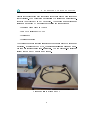
The railway system is based on a ground plate on which all railway system
components are mounted and wired. The locomotives drive on the rails which
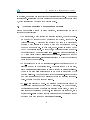
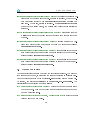
are interconnected by a crossing in the center and four turnouts, as shown in
Figure 1.
To provide information about the locomotives' positions, 16 reed
Figure 1: Image of the railway system
contacts are installed on the track bed. To simulate temporary erroneous reed
contact activations, pushbuttons are installed next to the six foremost reed
contacts.
Additionally, six rocker switches are installed.
2
They are used to
2
HARDWARE AND BASE SOFTWARE
disable the corresponding reed contacts in order to simulate a permanent reed
contact failure. The whole system is controlled by a serial communication protocol (IEA232) driven by an RSAPI backend. The programming environment
resides on a standard PC and includes the following base software:
•
Realtime Linux based on Ubuntu
•
Sun JRTS including JVM/JDK
•
Eclipse IDE
•
Eclipse workspace
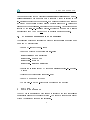
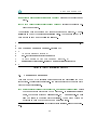
The Eclipse workspace contains all software components needed to implement
a steering.
AbstractSteering class and a sim RTT_Steering. The complete set-up including
It includes the RSAPI, the
ple example steering called
railway system and PC is shown in Figure 2.
Figure 2: Railway system and PC
3
3
3
STEERING IMPLEMENTATION
Steering Implementation
The realtime steering uses the AbstractSteering class to encapsulate all workow functionality. In order to write a custom steering, the user needs to derive
his steering class from AbstractSteering. User code should reside in the
steering package. To form a cleaner namespace an additional sub-package,
which holds the user implementation, may be created.
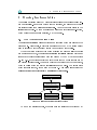
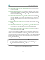
3.1
The
The AbstractSteering class
AbstractSteering
class provides some features which are useful to the
programmer. First of all, it provides an instance of the RSAPI (eld: api)
used to interact with the railway system (see Section 4 for details).
When the system starts up (time from starting the program till the control
ow reaches user code), the
AbstractSteering
initializes all locomotives and
turnouts to their default states which are dened by the RSAPI (see Section
4.3 and 4.4). It provides exactly one entry point for the whole control ow of
the derived steering class. This entry point is the abstract method drive(),
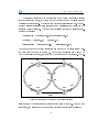
which is called after the system initialization is complete.
For information
about its class context, take a look at Figure 3. This gure also states that
AbstractSteering
is essentially a
NoHeapRealTimeThread.
NoHeapRealtimeThread
<<abstract>>
1
AbstractSteering
1
RSAPI
abstract void steer()
AnotherSteering
void steer()
Figure 3:
ReferenceSteering
void steer()
AbstractSteering
RTT_Steering
void steer()
class diagram
To make the steering secure, it implements the following behaviour: Any
4
3
exception that leaves
drive()
in a safe state (power-o ).
STEERING IMPLEMENTATION
up the call stack will put the railway system
Relevant error and/or warning messages will be
written to the standard error output. A minimal example of how to structure
the steering is shown in Listing 1.
1 public class StubSteeing extends AbstractSteering
2 {
3
/* Place your private fields here . */
4
5
6
7
8
9
10
11
public StubSteering ( RSAPI api ) throws Exception
{
super ( api );
/* Place memory allocation ( object creation ) here .
Note : do not use the api at this stage or the
AbstractSteering initialization sequence may fail ! */
}
12
13
14
15
16
17
@Override
public void steer () throws Exception
{
/* Perform initial api operations here ,
e. g. start locomotives . */
18
/* steering loop : */
while ( true )
{
/* Read reed contact states / perform steering step .
Note : Do not allocate any memory here ,
possible memory leak ! */
}
19
20
21
22
23
24
25
26
}
27 }
Listing 1: Stub steering implementation
5
3
STEERING IMPLEMENTATION
In addition, a real example is provided in the
is called
steering package.
The Example
RTT_Steering and just measures the round trip time of locomotive
1, which is instructed to drive with a certain speed.
3.2
Avoiding realtime programming pitfalls
Since a hard realtime system is being developed, special problems must be
taken into concideration:
•
The
Main
class, which creates the steering instance, boosts the prior-
ity of all JVM tasks above any process in the system, except the interrupt handlers.
A programming mistake may lead to a deadlocking
program which results in a system which no more responds to keyboard or mouse stimuli.
In this case, power-cycling is needed to get
the PC operational again. To avoid this, a defensive programming attitude is required: The main steering loop must give other processes some
NoHeapRealtimeThread.sleep() or through
NoHeapRealtimeThread.waitForNextPeriod() to avoid the continuous
CPU ticks either through
preemtion of these processes.
•
Do not allocate memory or call standard-library functions which may
allocate memory in the steering loop.
since a
NoHeapRealtimeThread
This will cause a memory leak,
is always located in
ImmortalMemory.
This memory area allows allocating memory which is never freed by the
garbage collector. The consequence is that all steering-relevant objects
and data structures need to be allocated before the steering loop is entered. See also the comments in Listing 1.
•
Do not write directly to a le the realtime behaviour will depend on
the harddisk access speed and the I/O scheduler.
On the other side,
pagefaults are occuring when les are accessed under Linux, which may
also inuence the realtime behaviour. If writing to a le is needed, use a
seperate non-realtime thread for this purpose and let the realtime thread
exchange data with it using a
WaitFreeWriteQueue.
6
4
An example showing the combination of a
RSAPI REFERENCE
NoHeapRealTimeThread and a Wait-
FreeWriteQueue to communicate with a standard Thread is located in the
rt-latency project in the workspace. It measures the latency and jitter of
the given NoHeapRealtimeThread using a periodic sleep of 1ms. Please take
also a look at the le README.TXT located in the project. A negative example
is given by the non-rt-latency project. It tries to make as much mistakes
as possible to show you what not to do in a realtime software project.
3.3
System requirements for x86 realtime
The following points are necessary in order to enable realtime programming
on an x86 PC architecture:
•
use an RT-enabled Linux-Kernel
•
use the modied "/etc/security/limits.conf":
@realtime
@realtime
@realtime
@realtime
•
soft cpu unlimited
- rtprio 100
- nice 40
- memlock unlimited
enable the "performance" CPU frequency scaler: "cpufreq-set -g performance"
4
•
disable the SMI if present ("smictrl -s 0")
•
use PS/2 mouse and keyboard
•
do not plug-in an USB-stick before powering on the machine
RSAPI reference
The RSAPI is an interface which is used to interact with each controllable
or accessible element of the railway system. The acronym stands for Railway
System Application Programming Interface.
7
4
RSAPI REFERENCE
The interface introduces an abstraction which helps to separate logical
elements like
locomotives, turnouts
and reed
contacts
from physical decoder
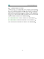
adressing conciderations. To identify each individual logical element, the enumerator classes Locomotive, Turnout and ReedContact reside in the
interface package (rsapi). The enumerator classes contain the following enumerator identiers:
• Locomotive → Locomotive.L0
and
Locomotive.L1
• Turnout → Turnout.T0 . . . Turnout.T3
• ReedContact → ReedContact.R0 . . . ReedContact.R15
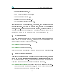
The turnout and reed contact identiers are mapped to physical railway system elements as stated in Figure 4.
Locomotive identiers are mapped to
both physical locomotives, according to the identiers on their sides. The inrear
R0
R1
T0
T1
R2
R3
R6
R7
R8
R9
R5
left
right
R4
R10
R12
R13
T2
R11
T3
R14
front
R15
Figure 4: Identier mapping on the railway system
terface is used to control dierent entities of the railway system. Based on this
separation, the following ve independend interface parts are established:
8
4
•
Power Interface (section 4.1)
•
Reed Contact Interface (section 4.2)
•
Turnout Interface (section 4.3)
•
Interface Locomotive (section 4.4)
•
Communication Interface (section 4.5)
RSAPI REFERENCE
All methods in the RSAPI are blocking. That means, they either succeed or an
exception is thrown. The maximum blocking time, as stated by the IntelliBox
manual, is 50ms. If asynchronous behavior is required, additional threads may
be implemented. For redundancy, it may be useful to create one thead for the
steering and one for the communication with the other steering PC.
4.1
Power Interface
The Power Interface provides two methods for turning all power-consuming
railway system components on and o. Please note that the locomotives and
turnouts can't be steered while the power is o.
void powerOn()
void powerOff()
turns the power on.
turns the power o.
Both methods throw an exception in case of a backend or communication error.
4.2
Reed Contact Interface
This part of the interface is used to retrieve the reed contact states. It consists
of the main methods
readReedContactStates and getReedContactState and
some additional utility methods. This interface is implemented stateful in order
to improve throughput and to simplify the resulting programs.
void readReedContactStates()
reads all 16 reed contact states from the hard-
ware backend into an internal buer. This method throws an exception
in case of a backend or communication error.
9
4
RSAPI REFERENCE
boolean getReedContactState(ReedContact contact)
returns the currently buf-
true is returned, then the contact was closed (active) when readReedContactStates was called the
last time. Otherwise, false is returned. If readReedContactStates
has never been called before, the default reed contact state (false) is
fered state of the given reed contact. If
returned.
double getReedContactLastChange(ReedContact contact)
returns the time (in
milliseconds) since the buered state of the given reed contact state has
changed.
boolean reedContactChanged(ReedContact contact)
returns
true
if the buf-
fered reed contact state has changed between two subsequent calls of
readReedContactStates.
boolean reedContactClosed(ReedContact contact)
returns
true if the buered
reed contact state has changed from open to closed between two subsequent calls of
readReedContactStates.
boolean reedContactOpened(ReedContact contact)
returns
true if the buered
reed contact state has changed from closed to open between two subsequent calls of
4.3
readReedContactStates.
Turnout Interface
The turnout interface is used to switch the individual turnouts. The state of
each turnout is buered, so inverting the turnout direction is possible without the otherwise needed extra application-level turnout state management.
On startup, the states are initialized to
TurnoutDir.DIR_STRAIGHTON.
The
descriptions of the interface methodes follow:
void writeTurnoutState(Turnout turnout)
writes the buered turnout state
to the hardware. This method throws an exception in case of a backend
or communication error.
void setTurnoutState(Turnout turnout, TurnoutState state)
turnout state to a new value.
10
sets the buered
4
TurnoutState getTurnoutState(Turnout turnout)
RSAPI REFERENCE
returns the buered tunout
state.
public void invertTurnoutState(Turnout turnout)
inverts the currently buf-
fered turnout state.
The interface does not perform any turnout switching on startup.
tialization is done by the
AbstractSteering
The ini-
class. The turnouts are put in a
known state as shown in the following listing 2.
1 RelativeTime turnoutSleepInterval = new RelativeTime (250 ,0);
2
3 for ( Turnout turnout : Turnout . values ())
4 {
/* Write default state */
api . writeTurnoutState ( turnout );
/* Wait 250 ms to let the turnout settle . */
NoHeapRealtimeThread . sleep ( turnoutSleepInterval );
5
6
7
8
9 }
Listing 2: Turnout initialization sequence
4.4
Locomotive Interface
This part of the RSAPI interface provides support for controlling the both
locomotives. This interface is stateful the state is written to the locomotive
decoder via
writeLocState.
void writeLocState(Locomotive locomotive, boolean writeFunctions)
writeFunctions is
LocFunction.F1 . . . LocFunction.F3 will
the buered locomotive state to the hardware.
true,
the buered states of
writes
1
also be written to the locomotive controller .
If
This method throws an
exception in case of a backend or communication error.
1 Since
ence.
the current locomotives do not implement these functions, this ag has no inu-
11
4
void setLocSpeed(Locomotive loc, LocSpeed speed)
RSAPI REFERENCE
sets the buered speed
for the locomotive.
LocSpeed getLocSpeed(Locomotive loc)
by
returns the last speed which was set
setLocomotiveSpeed or LocSpeed.SPEED_0 if setLocomotiveSpeed
has never been called before.
void setLocDirection(Locomotive loc, boolean forward)
sets the buered lo-
comotive direction. Note: The locomotives should only be driven in the
backward direction, because the reed contact magnet is placed below the
rear axis.
boolean getLocDirection(Locomotive loc)
returns the buered locomotive di-
rection.
void setLocFunction(Locomotive loc, LocFunction f, boolean enabled)
the buered locomotive function state to the value of
sets
enabled.
boolean getLocFunction(Locomotive loc, LocFunction function)
returns the
buered locomotive function state.
As in the turnout interface (see 4.3), the locomotive interface itself does not
perform any locomotive initialization on startup. Putting the locomotives into
a known state before executing the user code is also done by the
AbstractSteering
class (see Listing 3). The locomotive state after startup is: speed 0, direction
forward, functions disabled.
1 for ( Locomotive locomotive : Locomotive . values ())
2 {
3
4
/* Write default locomotive state to the decoder . */
api . writeLocState ( locomotive , true );
5 }
Listing 3: Locomotive initialization sequence
12
4
4.5
RSAPI REFERENCE
Communication Interface
The last part of the RSAPI interface allows to communicate with another steering PC over a serial communication channel. This port is directly beneath the
serial port, which is interconnected with the railway system.
This interface
is only needed for implementing hot-standby redundancy in the steering program. It may be used concurrent to the other interface parts by another thread
because it accesses a dedicated communication interface.
void writeCharToPC(char c)
char readCharFromPC()
sends a character to the other steering PC.
receives a character from the other steering PC.
Both methods throw an exception in the case of a communication error.
13