1
User Manual
Programming of TesiMod Operating
Terminals
Part Number:
80860.026
Version:
1
Date:
02.03.2005
Valid for:
TSwin 2.35
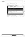
Version
1
Date
02.03.2005
Modifications
First Edition
This manual, including all illustrations contained herein, is copyright protected. Use of this manual by any third
party in departure from the copyright provision is forbidden. No part of this manual may be reproduced, translated or electronically or photographically archived or altered without the express written consent from Sütron
electronic GmbH. Violations shall be cause for damage liability.
Sütron electronic reserves the right to make any changes that contribute to technical improvement.
Overall Table of Contents
Overall Table of Contents
1
Important Notes ....................................................................................................... 1-1
1.1
2
Symbols .................................................................................................... 1-1
1.1.1
General Symbols ................................................................................. 1-1
1.1.2
Specific Symbols ................................................................................. 1-1
1.2
Safety Notes ............................................................................................. 1-2
1.3
Intended Use............................................................................................. 1-2
1.4
Target Group............................................................................................. 1-2
Operating Concept................................................................................................... 2-1
2.1
Introduction ............................................................................................... 2-1
2.1.1
2.2
3
Uniform device features ....................................................................... 2-1
Programming TesiMod Operating Devices ............................................... 2-3
2.2.1
Hardware Prerequisites ....................................................................... 2-3
2.2.2
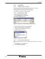
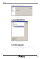
Installing TSwin.................................................................................... 2-4
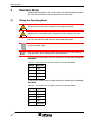
Standard Mode ........................................................................................................ 3-1
3.1
Setting the Operating Mode ...................................................................... 3-1
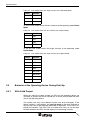
3.2
Behavior of the Operating Device During Start-Up ................................... 3-2
3.2.1
With Valid Project ................................................................................ 3-2
3.2.2
Without a Valid Project ........................................................................ 3-3
3.3
Communication with a Controller .............................................................. 3-3
3.4
Masks........................................................................................................ 3-4
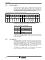
3.4.1
Mask Structure..................................................................................... 3-4
3.4.2
Mask Parameters................................................................................. 3-5
3.4.2.1
Mask Number .............................................................................................................3-5
3.4.2.2
Access Level...............................................................................................................3-5
3.4.2.3
Background Color .......................................................................................................3-5
3.4.2.4
Help Mask ...................................................................................................................3-6
3.4.2.5
Variables Management Topdown ...............................................................................3-6
3.4.2.6
Automatic Data Release .............................................................................................3-6
3.4.2.7
Reset Password..........................................................................................................3-6
3.4.2.8
Activate Help Mask .....................................................................................................3-6
3.4.3
System Masks ..................................................................................... 3-6
3.4.3.1
Setup Mask .................................................................................................................3-7
3.4.3.1.1
3.4.3.1.2
Password Protection for Setup Mask ...................................................................3-7
Suppressing the Setup Mask ...............................................................................3-7
3.4.3.2
Start-up Mask .............................................................................................................3-7
3.4.3.3
Password Mask ..........................................................................................................3-8
3.4.4
Input/Output Masks.............................................................................. 3-9
3.4.5
Help Masks .......................................................................................... 3-9
3.5
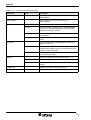
Variables ................................................................................................. 3-10
3.5.1
Symbolic Name.................................................................................. 3-10
3.5.2
Controller Address ............................................................................. 3-11
i
Overall Table of Contents
3.5.3
Representation Type.......................................................................... 3-11
3.5.3.1
Decimal Number....................................................................................................... 3-11
3.5.3.1.1
Standard............................................................................................................. 3-11
3.5.3.1.2
Timer .................................................................................................................. 3-12
3.5.3.1.3
Counter .............................................................................................................. 3-15
3.5.3.1.4
BCD Format ....................................................................................................... 3-16
3.5.3.2
Alphanumeric............................................................................................................ 3-17
3.5.3.3
Selection Text........................................................................................................... 3-18
3.5.3.4
Selection Image........................................................................................................ 3-19
3.5.3.5
Floating Point Number.............................................................................................. 3-20
3.5.3.6
Hexadecimal Number ............................................................................................... 3-21
3.5.3.7
Binary Number.......................................................................................................... 3-22
3.5.3.8
Bars .......................................................................................................................... 3-23
3.5.3.9
Curve ........................................................................................................................ 3-25
3.5.3.10
Fields ........................................................................................................................ 3-26
3.5.3.10.1
Message Field.................................................................................................... 3-26
3.5.3.10.2
Recipe Field ....................................................................................................... 3-27
3.5.3.10.3
ii
Table Field ......................................................................................................... 3-27
3.5.4
Field Type .......................................................................................... 3-28
3.5.4.1
Input.......................................................................................................................... 3-28
3.5.4.2
Output....................................................................................................................... 3-28
3.5.4.3
Password.................................................................................................................. 3-29
3.5.4.4
Cyclical ..................................................................................................................... 3-29
3.5.5
Format................................................................................................ 3-29
3.5.5.1
Only Positive............................................................................................................. 3-29
3.5.5.2
Display Leading Zeros.............................................................................................. 3-29
3.5.5.3
Field Length.............................................................................................................. 3-29
3.5.5.4
Fractional Digits........................................................................................................ 3-30
3.5.6
Documentation Value......................................................................... 3-30
3.5.7
Limits.................................................................................................. 3-30
3.5.8
Scaling ............................................................................................... 3-31
3.5.8.1
Scaled Input.............................................................................................................. 3-31
3.5.8.2
Scaled Output........................................................................................................... 3-31
3.5.9
Communication Definition .................................................................. 3-33
3.5.9.1
PLC Handshake ....................................................................................................... 3-33
3.5.9.2
With Enter................................................................................................................. 3-34
3.5.9.3
With +, –, or Enter .................................................................................................... 3-35
3.5.9.4
For all changes ......................................................................................................... 3-35
3.5.10
Access Type ...................................................................................... 3-35
3.5.10.1
Normal ...................................................................................................................... 3-35
3.5.10.2
Selective ................................................................................................................... 3-35
3.5.10.3
Article Administration................................................................................................ 3-36
3.5.10.4
Delete Article Administration .................................................................................... 3-36
3.5.11
Variable Type ..................................................................................... 3-36
3.5.11.1
Standard ................................................................................................................... 3-36
3.5.11.2
Timer ........................................................................................................................ 3-36
3.5.11.3
Counter..................................................................................................................... 3-36
3.5.11.4
BCD Number ............................................................................................................ 3-37
3.5.12
Attributes (Static or Dynamic) ............................................................ 3-37
3.5.12.1
Global ....................................................................................................................... 3-37
3.5.12.2
Inverse...................................................................................................................... 3-37
3.5.12.3
Flashing .................................................................................................................... 3-38
3.5.12.4
Underline .................................................................................................................. 3-38
Overall Table of Contents
3.5.12.5
Invisible .....................................................................................................................3-38
3.5.12.6
Non-Editable .............................................................................................................3-38
3.5.13
Font.................................................................................................... 3-38
3.5.14
Help Mask .......................................................................................... 3-39
3.5.15
Output Variables ................................................................................ 3-39
3.5.15.1
One-Off and Cyclical Output Variables .....................................................................3-39
3.5.15.2
Formatted Output......................................................................................................3-40
3.5.16
Input Variables ................................................................................... 3-40
3.5.16.1
Plausibility Check......................................................................................................3-41
3.5.17
System Variables............................................................................... 3-41
3.5.17.1
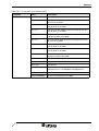
Basic Functions ........................................................................................................3-42
3.5.17.1.1
IntEraseEprom ...................................................................................................3-42
3.5.17.1.2
MainVersion .......................................................................................................3-42
3.5.17.1.3
ComVersion........................................................................................................3-42
3.5.17.1.4
UserVersion........................................................................................................3-42
3.5.17.1.5
Boot ....................................................................................................................3-43
3.5.17.1.6
LcdContrast ........................................................................................................3-43
3.5.17.1.7
LcdBackground ..................................................................................................3-43
3.5.17.1.8
LcdBackLight ......................................................................................................3-43
3.5.17.1.9
TurnOnTemp ......................................................................................................3-44
3.5.17.1.10
OsLanguage .......................................................................................................3-44
3.5.17.1.11
IdentName ..........................................................................................................3-44
3.5.17.1.12
IdentVersion .......................................................................................................3-44
3.5.17.1.13
IdentDate ............................................................................................................3-45
3.5.17.1.14
IdentTime ...........................................................................................................3-45
3.5.17.1.15
IdentCount ..........................................................................................................3-45
3.5.17.1.16
IdentRandom ......................................................................................................3-45
3.5.17.1.17
3.5.17.2
ComErrorRetry ...................................................................................................3-45
Communication SER1 ..............................................................................................3-47
3.5.17.2.1
ComDataLenA ....................................................................................................3-47
3.5.17.2.2
ComParityA ........................................................................................................3-47
3.5.17.2.3
ComStopBitsA ....................................................................................................3-47
3.5.17.2.4
ComBaudrateA ...................................................................................................3-48
3.5.17.2.5
ComHandshakeA ...............................................................................................3-48
3.5.17.2.6
ComDefaultA ......................................................................................................3-48
3.5.17.2.7
ComTimeout .......................................................................................................3-49
3.5.17.2.8
ComRetryTimeout ..............................................................................................3-49
3.5.17.2.9
ComSlaveNr .......................................................................................................3-49
3.5.17.2.10
ComErrorCode ...................................................................................................3-49
3.5.17.2.11
ComErrorSubcode..............................................................................................3-50
3.5.17.3
Error Statistics SER1 ................................................................................................3-50
3.5.17.3.1
ComParityCount .................................................................................................3-50
3.5.17.3.2
ComOverrunCount .............................................................................................3-51
3.5.17.3.3
ComFrameCount ................................................................................................3-51
3.5.17.4
Communication SER2 ..............................................................................................3-51
3.5.17.4.1
ComDataLenB ....................................................................................................3-51
3.5.17.4.2
ComParityB ........................................................................................................3-51
3.5.17.4.3
ComStopBitsB ....................................................................................................3-52
3.5.17.4.4
ComBaudrateB ...................................................................................................3-52
3.5.17.4.5
ComHandshakeB ...............................................................................................3-52
3.5.17.4.6
3.5.17.5
ComDefaultB ......................................................................................................3-52
Real-Time Clock .......................................................................................................3-53
3.5.17.5.1
RTCSec ..............................................................................................................3-53
3.5.17.5.2
RTCMin ..............................................................................................................3-53
3.5.17.5.3
RTCHour ............................................................................................................3-53
3.5.17.5.4
RTCDay..............................................................................................................3-53
iii
Overall Table of Contents
3.5.17.5.5
RTCMonth.......................................................................................................... 3-54
3.5.17.5.6
RTCYear ............................................................................................................ 3-54
3.5.17.5.7
RTCDayOfWeek ................................................................................................ 3-54
3.5.17.5.8
RTCDateFmt ...................................................................................................... 3-54
3.5.17.5.9
3.5.17.6
3.5.17.6.1
RepmanSortCrit ................................................................................................. 3-56
3.5.17.6.2
ClearRepBuf....................................................................................................... 3-56
3.5.17.6.3
RepmanRepPrint................................................................................................ 3-56
3.5.17.6.4
RepoutNr............................................................................................................ 3-57
3.5.17.6.5
RepoutDate ........................................................................................................ 3-57
3.5.17.6.6
RepoutTime........................................................................................................ 3-57
3.5.17.6.7
RepoutAnzYear.................................................................................................. 3-57
3.5.17.6.8
RepoutRepText .................................................................................................. 3-57
3.5.17.6.9
Repout RepText21 ............................................................................................. 3-58
3.5.17.6.10
RepoutRepText41 .............................................................................................. 3-58
3.5.17.6.11
RepoutRepText61 .............................................................................................. 3-58
3.5.17.6.12
RepmanQuitKey................................................................................................. 3-58
3.5.17.6.13
RepmanChgMask .............................................................................................. 3-59
3.5.17.6.14
RepoutQuitText .................................................................................................. 3-59
3.5.17.6.15
RepoutQuitText21 .............................................................................................. 3-59
3.5.17.6.16
RepoutQuitText41 .............................................................................................. 3-60
3.5.17.6.17
RepoutQuitText61 .............................................................................................. 3-60
3.5.17.6.18
RepoutQuitAnz................................................................................................... 3-60
3.5.17.6.19
RepoutMarker .................................................................................................... 3-60
3.5.17.6.20
RepoutSelectGroup............................................................................................ 3-61
3.5.17.6.21
RepoutSelectTime.............................................................................................. 3-61
3.5.17.6.22
3.5.17.7
RepoutGroup...................................................................................................... 3-61
Parallel Message System ......................................................................................... 3-61
3.5.17.7.1
RepmanSortCritP ............................................................................................... 3-61
3.5.17.7.2
RepoutNrP ......................................................................................................... 3-62
3.5.17.7.3
RepoutDateP...................................................................................................... 3-62
3.5.17.7.4
RepoutTimeP ..................................................................................................... 3-62
3.5.17.7.5
RepoutAnzYearP ............................................................................................... 3-62
3.5.17.7.6
RepoutRepTextP................................................................................................ 3-63
3.5.17.7.7
Repout RepText21P........................................................................................... 3-63
3.5.17.7.8
RepoutRepText41P............................................................................................ 3-63
3.5.17.7.9
RepoutRepText61P............................................................................................ 3-63
3.5.17.7.10
RepoutSelectGroupP ......................................................................................... 3-64
3.5.17.7.11
3.5.17.8
RepoutGroupP ................................................................................................... 3-64
Printer Control .......................................................................................................... 3-64
3.5.17.8.1
StopPrint ............................................................................................................ 3-64
3.5.17.8.2
BlockPrint ........................................................................................................... 3-64
3.5.17.8.3
PrintAllRep ......................................................................................................... 3-65
3.5.17.8.4
PrintAllState ....................................................................................................... 3-65
3.5.17.8.5
BlockPrintLong ................................................................................................... 3-65
3.5.17.9
iv
RTCYear2000 .................................................................................................... 3-54
Serial Message System............................................................................................ 3-56
Menu Control / Keys ................................................................................................. 3-65
3.5.17.9.1
NewMask ........................................................................................................... 3-65
3.5.17.9.2
VarTablenR0 ...................................................................................................... 3-66
3.5.17.9.3
VarTablenR1 ...................................................................................................... 3-66
3.5.17.9.4
HardCopy ........................................................................................................... 3-66
3.5.17.9.5
TabLeft ............................................................................................................... 3-66
3.5.17.9.6
TabRight............................................................................................................. 3-67
3.5.17.9.7
TabPgUp ............................................................................................................ 3-67
3.5.17.9.8
TabPgDn ............................................................................................................ 3-67
3.5.17.9.9
Shift .................................................................................................................... 3-67
3.5.17.9.10
ShiftCase............................................................................................................ 3-68
3.5.17.9.11
ShiftTouch .......................................................................................................... 3-69
3.5.17.9.12
KeyCursLeft ....................................................................................................... 3-69
Overall Table of Contents
3.5.17.9.13
KeyCursRight .....................................................................................................3-69
3.5.17.9.14
KeyCursUp .........................................................................................................3-69
3.5.17.9.15
KeyCursDown ....................................................................................................3-69
3.5.17.9.16
KeyHome............................................................................................................3-70
3.5.17.9.17
KeyHelp ..............................................................................................................3-70
3.5.17.9.18
KeyDot................................................................................................................3-70
3.5.17.9.19
KeyClear.............................................................................................................3-70
3.5.17.9.20
Key0 ...................................................................................................................3-70
3.5.17.9.21
Key1 ...................................................................................................................3-71
3.5.17.9.22
Key2 ...................................................................................................................3-71
3.5.17.9.23
Key3 ...................................................................................................................3-71
3.5.17.9.24
Key4 ...................................................................................................................3-71
3.5.17.9.25
Key5 ...................................................................................................................3-71
3.5.17.9.26
Key6 ...................................................................................................................3-72
3.5.17.9.27
Key7 ...................................................................................................................3-72
3.5.17.9.28
Key8 ...................................................................................................................3-72
3.5.17.9.29
Key9 ...................................................................................................................3-72
3.5.17.9.30
KeyPlus ..............................................................................................................3-72
3.5.17.9.31
KeyMinus............................................................................................................3-73
3.5.17.9.32
KeyEnter.............................................................................................................3-73
3.5.17.9.33
KeyEdit ...............................................................................................................3-73
3.5.17.10
Password ..................................................................................................................3-73
3.5.17.10.1
MskChgPasswd..................................................................................................3-73
3.5.17.10.2
MskChgResPasswd ...........................................................................................3-74
3.5.17.10.3
ChangePasswd ..................................................................................................3-74
3.5.17.10.4
FlashPasswd ......................................................................................................3-74
3.5.17.10.5
PasswdInactive ..................................................................................................3-74
3.5.17.10.6
ActViewLevel ......................................................................................................3-75
3.5.17.10.7
3.5.17.11
ActEditLevel .......................................................................................................3-75
Recipes .....................................................................................................................3-76
3.5.17.11.1
SelectDSNr.........................................................................................................3-76
3.5.17.11.2
SelectDSName ...................................................................................................3-76
3.5.17.11.3
DestDSNr ...........................................................................................................3-76
3.5.17.11.4
DSCopy ..............................................................................................................3-76
3.5.17.11.5
DSDelete ............................................................................................................3-77
3.5.17.11.6
ActDSName........................................................................................................3-77
3.5.17.11.7
SelectRezeptNr ..................................................................................................3-77
3.5.17.11.8
SelectRezeptName ............................................................................................3-77
3.5.17.11.9
DSDeleteState....................................................................................................3-78
3.5.17.11.10
LoadRezName ...................................................................................................3-78
3.5.17.11.11
DSDownload ......................................................................................................3-78
3.5.17.11.12
DSDnloadBreak..................................................................................................3-78
3.5.17.11.13
DSDnloadState...................................................................................................3-78
3.5.17.11.14
LoadDSName .....................................................................................................3-79
3.5.17.11.15
StartSave............................................................................................................3-79
3.5.17.11.16
SaveState ...........................................................................................................3-79
3.5.17.11.17
StartRestore .......................................................................................................3-79
3.5.17.11.18
RestoreState ......................................................................................................3-80
3.5.17.11.19
RestoreLineNr ....................................................................................................3-80
3.5.17.11.20
StartRezPrint ......................................................................................................3-80
3.5.17.11.21
RezPrintState .....................................................................................................3-80
3.5.17.11.22
StartUpload ........................................................................................................3-81
3.5.17.11.23
UploadDSNr .......................................................................................................3-81
3.5.17.11.24
3.5.17.12
3.5.17.12.1
3.5.17.13
UploadState........................................................................................................3-81
Running Time Meters ...............................................................................................3-81
Counter1 to Counter8 .........................................................................................3-81
Loop-Through Operation ..........................................................................................3-83
3.5.17.13.1
Pg2Sps ...............................................................................................................3-83
3.5.17.13.2
Pg2SpsState ......................................................................................................3-83
v
Overall Table of Contents
3.5.17.14
3.5.17.14.1
3.5.17.15
3.5.17.15.1
ChrsetName ....................................................................................................... 3-83
Maintenance ............................................................................................................. 3-84
User1 to User5 ................................................................................................... 3-84
3.5.17.15.2
LCDADCInput .................................................................................................... 3-84
3.5.17.15.3
LCDDACOutput.................................................................................................. 3-84
3.5.17.15.4
Break.................................................................................................................. 3-84
3.5.17.15.5
StartCalibrationTouch ........................................................................................ 3-85
3.5.17.15.6
StateCalibrationTouch........................................................................................ 3-85
3.5.17.15.7
MaskStartupTime ............................................................................................... 3-85
3.5.17.15.8
3.5.17.16
KeyResponseTime............................................................................................. 3-86
Editors ...................................................................................................................... 3-86
3.5.17.16.1
EditInvers ........................................................................................................... 3-86
3.5.17.16.2
EditEnter ............................................................................................................ 3-86
3.5.17.16.3
3.5.17.17
StatePerm .......................................................................................................... 3-86
Help .......................................................................................................................... 3-87
3.5.17.17.1
StateHelp ........................................................................................................... 3-87
3.5.17.17.2
Message............................................................................................................. 3-87
3.5.17.17.3
QuitMessage ...................................................................................................... 3-87
3.5.17.17.4
StatusText .......................................................................................................... 3-88
3.5.17.17.5
StatusText21 ...................................................................................................... 3-88
3.5.17.17.6
StatusText41 ...................................................................................................... 3-88
3.5.17.17.7
StatusText61 ...................................................................................................... 3-88
3.5.17.18
3.5.17.18.1
Print Logs ................................................................................................................. 3-89
SelectPrintLog.................................................................................................... 3-89
3.5.17.18.2
StartPrintLog ...................................................................................................... 3-89
3.5.17.18.3
StatePrintLog ..................................................................................................... 3-89
3.5.17.18.4
3.5.17.19
PageNumber ...................................................................................................... 3-89
Compact Flash Card................................................................................................. 3-90
3.5.17.19.1
CardFileName .................................................................................................... 3-90
3.5.17.19.2
CardApplicationMove ......................................................................................... 3-90
3.5.17.19.3
CardDataSetMove.............................................................................................. 3-90
3.5.17.19.4
CardFileDelete ................................................................................................... 3-91
3.5.17.19.5
CardFileError...................................................................................................... 3-91
3.5.17.19.6
3.5.17.20
3.5.17.20.1
3.5.17.20.2
3.5.17.21
3.5.17.21.1
3.6
CFCardError....................................................................................................... 3-92
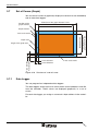
Set of Curves (Graph) .............................................................................................. 3-92
DataLogTrig ....................................................................................................... 3-92
DataLogClear ..................................................................................................... 3-93
Sound ....................................................................................................................... 3-93
Volume ............................................................................................................... 3-93
Dynamic Attributes .................................................................................. 3-93
3.6.1
Underline............................................................................................ 3-94
3.6.2
Inverse ............................................................................................... 3-94
3.6.3
Flashing ............................................................................................. 3-94
3.6.4
Invisible .............................................................................................. 3-95
3.6.5
Non-Editable ...................................................................................... 3-95
3.6.6
Foreground ........................................................................................ 3-95
3.6.7
Background ........................................................................................ 3-95
3.6.8
Attribute Priorities............................................................................... 3-95
3.7
3.7.1
vi
Loadable Character Set............................................................................................ 3-83
Set of Curves (Graph) ............................................................................. 3-96
Data Logger ....................................................................................... 3-96
3.8
Images .................................................................................................... 3-98
3.9
Symbols .................................................................................................. 3-98
Overall Table of Contents
3.10
Buttons.................................................................................................... 3-99
3.10.1
Content of Buttons ............................................................................. 3-99
3.10.2
Functions of Buttons ........................................................................ 3-100
3.10.3
Representation of Buttons ............................................................... 3-100
3.10.3.1
Frames for Buttons .................................................................................................3-101
3.11
Function Keys/Softkeys ........................................................................ 3-103
3.11.1
Direct Selector Keys ........................................................................ 3-104
3.11.2
Function Keys in the Controller........................................................ 3-104
3.11.3
Softkeys ........................................................................................... 3-104
3.11.4
Reaction Time of Function and Soft Keys ....................................... 3-105
3.11.5
Using Control Keys as Function Keys ............................................. 3-106
3.11.6
Function Keys Controlling Parallel Outputs ..................................... 3-106
3.11.7
Status LEDs of Function Keys ......................................................... 3-106
3.12
Running Time Meter ............................................................................. 3-107
3.13
Read Coordination Byte........................................................................ 3-108
3.13.1
Editing Request ............................................................................... 3-109
3.13.2
Editing Status................................................................................... 3-109
3.13.3
Refresh Request .............................................................................. 3-109
3.13.4
Liveness Flag................................................................................... 3-110
3.13.5
Data Set Download Active ............................................................... 3-110
3.14
Write Coordination Byte ........................................................................ 3-110
3.14.1
External Data Release ..................................................................... 3-111
3.14.2
Refresh Acknowledgment ................................................................ 3-111
3.14.3
Delete Password.............................................................................. 3-111
3.14.4
Liveness Flag................................................................................... 3-112
3.14.5
Data Set Download Release............................................................ 3-112
3.15
The Cyclical Polling Area ...................................................................... 3-113
3.15.1
Byte-Oriented Polling Area .............................................................. 3-114
3.15.2
Word-Oriented Polling Area ............................................................. 3-116
3.15.3
Serial Message Channel.................................................................. 3-116
3.15.4
Image of the Status LEDs ................................................................ 3-117
3.15.5
Polling Time ..................................................................................... 3-117
3.15.6
Size of the Polling Area ................................................................... 3-118
3.16
Control Codes ....................................................................................... 3-118
3.16.1
Delete Data Logger.......................................................................... 3-120
3.16.2
Trigger Data Logger......................................................................... 3-120
3.16.3
Write Values of Running Time Meters to Controller......................... 3-120
3.16.4
Switch to Another Language............................................................ 3-120
3.16.5
Automatic Data Release for Scanner Module.................................. 3-121
3.16.6
Reload Event-Controlled Variable Values ....................................... 3-121
3.16.7
Transfer Single Data Set from Operating Device to Controller ........ 3-121
3.16.8
Delete Acknowledged Messages from Serial Message Memory..... 3-121
3.16.9
Cancel Printing the Print Log ........................................................... 3-121
3.16.10
Printing a Print Log .......................................................................... 3-122
vii
Overall Table of Contents
3.16.11
Printing a Data Set ........................................................................... 3-122
3.16.12
Set Clock in Operating Device ......................................................... 3-122
3.16.13
Data Set Transfer from Controller to
Operating Device (Block Mode) ....................................................... 3-123
3.16.14
Data Set Transfer from Operating Device to Controller ................... 3-123
3.16.15
Send Keyboard Image to Controller................................................. 3-123
3.16.16
Data Set Transfer from Controller to
Operating Device (Single Mode) ...................................................... 3-123
3.16.17
Erase Serial Message Memory ........................................................ 3-124
3.16.18
Refresh Message System ................................................................ 3-124
3.17
Password Protection ............................................................................. 3-125
3.17.1
Password Management ................................................................... 3-126
3.17.2
Reactivate Password Protection ...................................................... 3-127
3.17.3
Password Mask and Password Functions ....................................... 3-127
3.18
Real Time Clock in the Operating Device ............................................. 3-128
3.18.1
Date and Time Image ...................................................................... 3-128
3.18.2
Setting the Real Time Clock from the Controller.............................. 3-130
3.18.3
Transferring the Real-Time to the Controller ................................... 3-130
3.19
Help System.......................................................................................... 3-131
3.19.1
Default Help Mask............................................................................ 3-131
3.19.2
Help Mask for Masks ....................................................................... 3-131
3.19.3
Help Mask for Input Variable............................................................ 3-131
3.19.4
Help Mask for Message Masks ........................................................ 3-132
3.20
Print Logs .............................................................................................. 3-133
3.20.1
3.21
System Parameters............................................................................... 3-134
3.21.1
General Parameters......................................................................... 3-134
3.21.2
Polling Area...................................................................................... 3-135
3.21.3
Terminal Clock ................................................................................. 3-136
3.21.4
Running Time Meters....................................................................... 3-136
3.21.5
Message System ............................................................................. 3-137
3.21.6
Variant Options ................................................................................ 3-138
3.21.7
Password Management ................................................................... 3-139
3.21.8
Communication SER2...................................................................... 3-139
3.21.8.1
Connecting a Scanner ............................................................................................ 3-139
3.21.9
Gateway ........................................................................................... 3-140
3.21.10
Data Set Transfer............................................................................. 3-140
3.21.11
Parallel Outputs ............................................................................... 3-140
3.21.12
Touch Parameters ........................................................................... 3-141
3.21.13
Print Logs ......................................................................................... 3-141
3.22
viii
Escape Sequences for Print Logs.................................................... 3-133
Message System................................................................................... 3-143
3.22.1
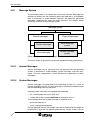
Internal Messages............................................................................ 3-143
3.22.2
System Messages............................................................................ 3-143
3.22.2.1
System Message 1 - Wrong format ........................................................................ 3-145
Overall Table of Contents
3.22.2.2
System Message 2 - Value too large ......................................................................3-145
3.22.2.3
System Message 3 - Value too small .....................................................................3-145
3.22.2.4
System Message 4 - Replace battery .....................................................................3-146
3.22.2.5
System Message 5 - Message overflow .................................................................3-146
3.22.2.6
System Message 6 - New message .......................................................................3-146
3.22.2.7
System Message 7 - Message buffer full................................................................3-146
3.22.2.8
System Message 8 - Invalid mask no ....................................................................3-146
3.22.2.9
System Message 9 - Invalid message no. .............................................................3-146
3.22.2.10
System Message 10 - Print log invalid....................................................................3-146
3.22.2.11
System Message 11 - Interface in use ...................................................................3-146
3.22.2.12
System Message 12 - Invalid Password .................................................................3-147
3.22.2.13
System Message 13 - Password unchanged .........................................................3-147
3.22.2.14
System Message 14 - Overvoltage.........................................................................3-147
3.22.2.15
System Message 15 - Data set protected...............................................................3-147
3.22.2.16
System Message 16 - Illegal data set .....................................................................3-147
3.22.2.17
System Message 17 - Data set unknown ...............................................................3-147
3.22.2.18
System Message 18 - Data set memory full ...........................................................3-147
3.22.2.19
System message 19 - Data set active ....................................................................3-147
3.22.2.20
System Message 20 - Data set transfer .................................................................3-147
3.22.2.21
System Message 21 - Password missing ...............................................................3-148
3.22.2.22
System Message 22 - Editing mode active.............................................................3-148
3.22.2.23
System Message 23 - Data set file error ................................................................3-148
3.22.2.24
System Message 24 - Data set format ...................................................................3-148
3.22.2.25
System Message 25 - Number invalid ....................................................................3-148
3.22.2.26
System Message 26 - Loop-through active ............................................................3-148
3.22.2.27
System Message 27 - No data set address ............................................................3-148
3.22.2.28
System Message 28 - Recipe unknown .................................................................3-148
3.22.2.29
System Message 29 - Data set download ..............................................................3-148
3.22.2.30
System Message 30 - Scanner error ......................................................................3-149
3.22.2.31
System Message 31 - Print log unknown ...............................................................3-149
3.22.2.32
System Message 32 - Error on changing the language..........................................3-149
3.22.2.33
System Message 33 - Flash card information ........................................................3-149
3.22.2.34
System Message 34 - New appl. necessary...........................................................3-149
3.22.3
Suppressing the Display of System Messages................................ 3-149
3.22.4
Error messages ............................................................................... 3-150
3.22.5
External Messages .......................................................................... 3-153
3.22.5.1
Structure of an External Message ..........................................................................3-153
3.22.5.1.1
Message Number .............................................................................................3-154
3.22.5.1.2
Message Text and Variable..............................................................................3-154
3.22.5.2
Size of Message Memory .......................................................................................3-155
3.22.5.3
Message Sorting .....................................................................................................3-155
3.22.5.4
Message Priority for Direct Display.........................................................................3-156
3.22.5.5
Printing the Message Memory ................................................................................3-156
3.22.5.6
Direct Call of the Message Mask ............................................................................3-156
3.22.5.7
Message Output Formats .......................................................................................3-157
3.22.5.8
Zooming Messages ................................................................................................3-159
3.22.5.9
Acknowledging Messages ......................................................................................3-159
3.22.6
Serial Message System ................................................................... 3-159
3.22.6.1
Full-Page Message Output .....................................................................................3-160
3.22.6.2
Outputting Messages to a Logging Printer .............................................................3-160
3.22.6.3
Erasing the Message Memory Externally ...............................................................3-161
3.22.7
Parallel Message System (Status Messages) ................................. 3-161
3.22.7.1
Settings for Status Messages .................................................................................3-161
ix
Overall Table of Contents
3.22.7.1.1
Size in Bytes .................................................................................................... 3-161
3.22.7.1.2
Polling Time ..................................................................................................... 3-163
3.22.7.1.3
Variables for Status Messages ........................................................................ 3-163
3.22.7.1.4
Variable for Acknowledging Messages ............................................................ 3-163
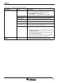
3.23
3.23.1
Structure of a Recipe ....................................................................... 3-166
3.23.2
Working with Recipes and Data Sets............................................... 3-166
3.23.2.1
Selecting a Recipe.................................................................................................. 3-166
3.23.2.2
Selecting a Data Set............................................................................................... 3-167
3.23.2.3
Copying a Data Set ................................................................................................ 3-167
3.23.2.4
Deleting a Data Set ................................................................................................ 3-168
3.23.2.5
Modifying a Data Set .............................................................................................. 3-168
3.23.3
Data Set Transfer to/from Controller ................................................ 3-169
3.23.3.1
Transfer to the Controller (Operator-Controlled) .................................................... 3-170
3.23.3.2
Transfer to the Operating Device (Operator-Controlled) ........................................ 3-171
3.23.3.3
Transferring Data Sets to / from a PC .................................................................... 3-171
3.23.3.4
Transfer to a PC ..................................................................................................... 3-172
3.23.3.5
Transfer from a PC ................................................................................................. 3-172
3.23.3.6
Structure of a Data Set File .................................................................................... 3-173
3.23.3.7
Printing Data Sets................................................................................................... 3-175
3.23.3.8
Memory Requirement for Data Sets ....................................................................... 3-175
3.24
Memory Requirement for Messages and Data Sets ............................. 3-176
3.25
Application ID ........................................................................................ 3-177
3.26
Version Number .................................................................................... 3-178
3.27
Image of Mask Number......................................................................... 3-178
3.28
Image of User Mode Switch .................................................................. 3-178
3.29
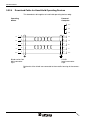
Parallel Outputs..................................................................................... 3-179
3.30
Screen Saver ........................................................................................ 3-179
3.31
Documentation ...................................................................................... 3-180
3.31.1
Global Settings ....................................................................................................... 3-180
3.31.1.2
Projects................................................................................................................... 3-180
3.31.1.3
Masks ..................................................................................................................... 3-180
3.31.1.4
Recipes................................................................................................................... 3-181
3.31.1.5
Help Masks............................................................................................................. 3-181
3.31.1.6
System Messages .................................................................................................. 3-182
3.31.1.7
Messages ............................................................................................................... 3-182
Downloading a Project .......................................................................... 3-183
3.32.1
Automatic Download Function ......................................................... 3-183
3.32.2
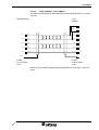
Download Cable 9 Pin ..................................................................... 3-184
3.32.3
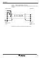
Download Cable 25 Pin ................................................................... 3-185
3.32.4
Download Cable for Hand-Held Operating Devices......................... 3-186
3.33
x
Documentation Parameters ............................................................. 3-180
3.31.1.1
3.32
4
Recipes ................................................................................................. 3-163
Simulation Without a Controller (Demo Mode)...................................... 3-187
Transparent Mode....................................................................................................4-1
4.1
Setting the Operating Mode ...................................................................... 4-1
4.2
Behavior of the Operating Device During Start-Up ................................... 4-2
Overall Table of Contents
4.3
Communication in Transparent Mode....................................................... 4-2
4.4
Parameters for Interface X2, X3 SER1 ..................................................... 4-3
4.4.1
Receive Buffer for Interface X2............................................................ 4-3
4.4.2
Setup Menu Function........................................................................... 4-3
4.4.3
Changing the Parameters in the Setup Menu...................................... 4-3
4.5
Display ...................................................................................................... 4-4
4.5.1
4.6
Character Set, Character Attributes..................................................... 4-5
Keys .......................................................................................................... 4-5
4.6.1
4.7
Control Characters for the Interface.......................................................... 4-7
4.7.1
LED Codes for the Operating Devices................................................. 4-8
4.7.2
Control Sequences for Operating Devices .......................................... 4-9
4.8
5
Key Codes for Each Operating Device ................................................ 4-5
Error Messages....................................................................................... 4-12
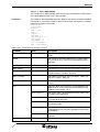
Controller and Bus Connections .............................................................................. 5-1
5.1
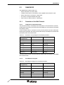
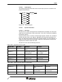
3964 RK512 .............................................................................................. 5-3
5.1.1
Procedure of the 3964 Protocol ........................................................... 5-3
5.1.1.1
Telegram for Connection Setup ..................................................................................5-3
5.1.1.2
Data Request Telegram..............................................................................................5-3
5.1.1.3
Data Request Telegram Header.................................................................................5-4
5.1.1.3.1
Specification of the Data Types in the "Data Request" Telegram Header ...........5-5
5.1.1.4
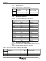
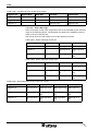
Response Telegram ...................................................................................................5-6
5.1.1.5
Data Transmission Telegram......................................................................................5-6
5.1.1.6
Data Transmission Telegram Header .........................................................................5-6
5.1.1.7
Special Features of the 3964R Protocol .....................................................................5-7
5.1.1.7.1
Destination Information for a Write-Access via a Data Block ...............................5-7
5.1.1.7.2
Restrictions of the 3964R Protocol .......................................................................5-8
5.1.2
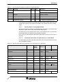
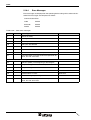
Data Types .......................................................................................... 5-8
5.1.3
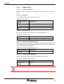
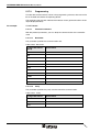
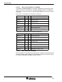
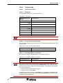
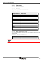
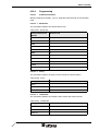
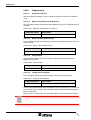
Programming ..................................................................................... 5-10
5.1.3.1
Protocol Parameters .................................................................................................5-10
5.1.3.1.1
Baud Rate ..........................................................................................................5-10
5.1.3.1.2
Parity ..................................................................................................................5-10
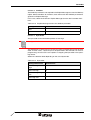
5.1.3.1.3
Handshake .........................................................................................................5-10
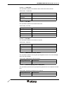
5.1.3.1.4
Data Bits .............................................................................................................5-11
5.1.3.1.5
Stop Bits .............................................................................................................5-11
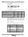
5.1.3.1.6
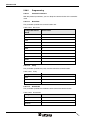
Use Coordination Flag........................................................................................5-11
5.1.3.1.7
Coordination Flag ...............................................................................................5-11
5.1.3.1.8
Bit Number .........................................................................................................5-11
5.1.3.1.9
Data Block Number ............................................................................................5-12
5.1.3.1.10
Data Block Word ................................................................................................5-12
5.1.3.1.11
Floating Point Number in the Siemens Format ..................................................5-12
5.1.3.1.12
Block Check .......................................................................................................5-12
5.1.3.1.13
CPU Number ......................................................................................................5-12
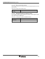
5.1.3.1.14
Full Duplex .........................................................................................................5-13
5.1.3.1.15
Half Duplex .........................................................................................................5-13
5.1.3.2
Input Syntax ..............................................................................................................5-14
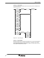
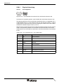
5.1.4
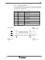
Physical Interfacing............................................................................ 5-15
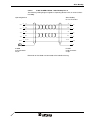
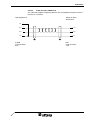
5.1.4.1
Pin Assignment for Operating Devices with an Universal Interface..........................5-15
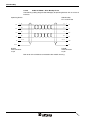
5.1.4.2
Pin Assignment for Operating Devices without an Universal Interface.....................5-16
5.1.4.3
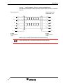
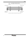
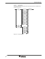
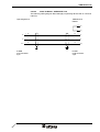
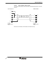
Cable X3 SER1 TTY / 20 mA - Siemens S5 CP524/525 and
Helmholz SAS 523/525.............................................................................................5-18
xi
Overall Table of Contents
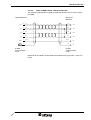
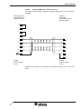
5.1.4.4
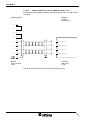
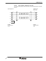
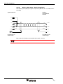
Cable X2 TTY / 20 mA - Siemens S5 CP524/525 and Helmholz SAS 523/525....... 5-19
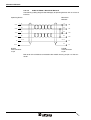
5.1.4.5
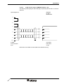
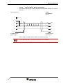
Cable X3 SER1 RS232 - Siemens S5 CP523/525................................................... 5-20
5.1.4.6
Cable X2 RS232 - Siemens S5 CP 523/525 ............................................................ 5-21
5.1.4.7
Cable X3 SER1 RS485 - Siemens S5 CP 523/525.................................................. 5-22
5.1.4.8
Cable X2 RS485 - Siemens S5 CP 523/525 ............................................................ 5-23
5.1.4.9
Cable X3 SER1 RS485 - Siemens S5 with Helmholz SAS 523/525 ........................ 5-24
5.1.4.10
Cable X2 RS485 - Siemens S5 with Helmholz SAS 523/525................................... 5-25
5.1.4.11
Cable X3 SER1 RS485 - Siemens S5 with VIPA BGM79-43................................... 5-26
5.1.4.12
Cable X2 RS485 - Siemens S5 with VIPA BGM79-43 ............................................. 5-27
5.1.4.13
Cable X3 SER1 TTY / 20 mA - EBERLE PLS514 - K43 .......................................... 5-28
5.1.4.14
Cable X2 TTY / 20 mA - EBERLE PLS514 - K43..................................................... 5-29
5.1.4.15
Cable X3 SER1 RS232 - EBERLE PLS514 - K43.................................................... 5-30
5.1.4.16
Cable X2 RS232 - EBERLE PLS514 - K43 .............................................................. 5-31
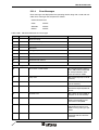
5.1.5
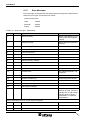
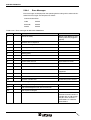
Error Messages.................................................................................. 5-32
5.1.6
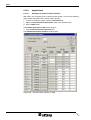
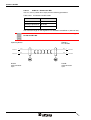
Applications........................................................................................ 5-34
5.1.6.1
Connection to Siemens S5 115U ............................................................................. 5-34
5.1.6.2
Connection to EBERLE PLS514 with communication block K43 ............................. 5-35
5.1.6.2.1
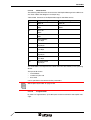
Protocol Parameters for TTY / 20 mA ................................................................ 5-36
5.1.6.2.2
Protocol Parameters for RS232 ......................................................................... 5-36
5.1.6.2.3
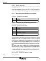
Initializing the K43 module ................................................................................. 5-37
5.2
3S sarti .................................................................................................... 5-43
5.2.1
Data Types......................................................................................... 5-43
5.2.1.1
Single Variables........................................................................................................ 5-43
5.2.1.2
String Variables ........................................................................................................ 5-43
5.2.2
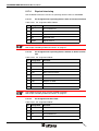
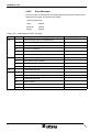
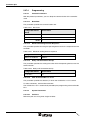
Programming ..................................................................................... 5-44
5.2.2.1
Protocol Parameters................................................................................................. 5-44
5.2.2.1.1
5.2.2.2
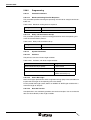
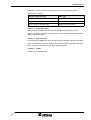
System Parameters .................................................................................................. 5-44
5.2.2.2.1
Poll Area............................................................................................................. 5-44
5.2.2.2.2
Status Messages................................................................................................ 5-44
5.2.2.2.3
Date and Time.................................................................................................... 5-44
5.2.2.2.4
Variant Buffer ..................................................................................................... 5-44
5.2.2.2.5
Tables ................................................................................................................ 5-45
5.2.3
Error Messages.................................................................................. 5-46
5.2.4
Applications........................................................................................ 5-47
5.2.4.1
CoDeSys Version 2.2 or Higher ............................................................................... 5-47
5.2.4.1.1
Declaring Global Variables................................................................................. 5-47
5.2.4.1.2
Activate Output into Symbol File ........................................................................ 5-47
5.2.4.1.3
Target System Settings...................................................................................... 5-49
5.3
xii
Path for Variable List *.sym................................................................................ 5-44
3S serial .................................................................................................. 5-51
5.3.1
Data Types......................................................................................... 5-51
5.3.1.1
Single Variables........................................................................................................ 5-51
5.3.1.2
String Variables ........................................................................................................ 5-51
5.3.2
Programming ..................................................................................... 5-52
5.3.2.1
Protocol Parameters................................................................................................. 5-52
5.3.2.1.1
Baud Rate .......................................................................................................... 5-52
5.3.2.1.2
Parity .................................................................................................................. 5-52
5.3.2.1.3
Data Bits............................................................................................................. 5-52
5.3.2.1.4
Stop Bits............................................................................................................. 5-52
5.3.2.1.5
Waiting Time for Response................................................................................ 5-53
5.3.2.1.6
Delay until Connection Set-Up ........................................................................... 5-53
5.3.2.1.7
Byte Order.......................................................................................................... 5-53
5.3.2.1.8
Controllers.......................................................................................................... 5-53
Overall Table of Contents
5.3.2.1.9
5.3.2.2
Path for Variable List *.sym ................................................................................5-53
System Parameters ..................................................................................................5-54
5.3.2.2.1
Poll Area .............................................................................................................5-54
5.3.2.2.2
Status Messages ................................................................................................5-54
5.3.2.2.3
5.3.2.3
Date and Time ....................................................................................................5-54
Physical Interfacing...................................................................................................5-55
5.3.2.3.1
Pin Assignment for Operating Devices with an Universal Interface ...................5-55
5.3.2.3.2
Pin Assignment for Operating Devices without an Universal Interface ..............5-55
5.3.2.3.3
Cable X3 SER1 RS232 - Schraml PLC FWM105 ..............................................5-56
5.3.2.3.4
Cable X2 RS232 - Schraml SPS FWM105 ........................................................5-57
5.3.2.3.5
Cable X3 SER1 RS232 - Schraml SPS FWM160 ..............................................5-58
5.3.2.3.6
Cable X2 RS232 - Schraml SPS FWM160 ........................................................5-59
5.3.3
Error Messages ................................................................................. 5-60
5.3.4
Applications ....................................................................................... 5-61
5.3.4.1
CoDeSys Version 2.2 or Higher................................................................................5-61
5.3.4.1.1
Declaring Global Variables .................................................................................5-61
5.3.4.1.2
Activate Output into Symbol File ........................................................................5-61
5.3.4.1.3
Variable List........................................................................................................5-63
5.4
3S Symbolic ............................................................................................ 5-65
5.4.1
Data Types ........................................................................................ 5-65
5.4.1.1
Single Variables ........................................................................................................5-65
5.4.1.2
String Variables ........................................................................................................5-65
5.4.2
Programming ..................................................................................... 5-66
5.4.2.1
Protocol Parameters .................................................................................................5-66
5.4.2.1.1
Baud rate ............................................................................................................5-66
5.4.2.1.2
Parity ..................................................................................................................5-66
5.4.2.1.3
Data Bits .............................................................................................................5-66
5.4.2.1.4
Stop Bits .............................................................................................................5-66
5.4.2.1.5
Waiting Time for Response ................................................................................5-67
5.4.2.1.6
Delay until Connection Set-Up ...........................................................................5-67
5.4.2.1.7
Byte Order ..........................................................................................................5-67
5.4.2.1.8
Controllers ..........................................................................................................5-67
5.4.2.1.9
5.4.2.2
Path for Variable List *.sym ................................................................................5-67
System Parameters ..................................................................................................5-67
5.4.2.2.1
Poll Area .............................................................................................................5-67
5.4.2.2.2
Status Messages ................................................................................................5-68
5.4.2.2.3
Date and Time ....................................................................................................5-68
5.4.3
Physical Interfacing............................................................................ 5-69
5.4.3.1
Pin assignment for operating devices with a universal interface ..............................5-69
5.4.3.2
Pin Assignment for Operating Devices without an Universal Interface.....................5-69
5.4.3.3
Cable X3 SER1 RS232 - Schraml PLC FWM105.....................................................5-70
5.4.3.4
Cable X2 RS232 - Schraml SPS FWM105 ...............................................................5-71
5.4.3.5
Cable X3 SER1 RS232 - Schraml SPS FWM160 ....................................................5-72
5.4.3.6
Cable X2 RS232 - Schraml SPS FWM160 ...............................................................5-73
5.4.4
Error Messages ................................................................................. 5-74
5.4.5
Applications ....................................................................................... 5-75
5.4.5.1
CoDeSys Version 2.2 or Higher................................................................................5-75
5.4.5.1.1
Declaring Global Variables .................................................................................5-75
5.4.5.1.2
Activate Output into Symbol File ........................................................................5-75
5.4.5.1.3
Variable List........................................................................................................5-77
5.5
ABB Arcnet ............................................................................................. 5-79
5.5.1
Hardware ........................................................................................... 5-79
5.5.2
Telegram Setup ................................................................................. 5-79
xiii
Overall Table of Contents
5.5.3
Data Types......................................................................................... 5-80
5.5.4
Programming ..................................................................................... 5-82
5.5.4.1
Protocol Parameters................................................................................................. 5-82
5.5.4.1.1
Maximum Waiting Time For Response .............................................................. 5-82
5.5.4.1.2
Delay until Connection Set-Up ........................................................................... 5-82
5.5.4.1.3
Baud Rate .......................................................................................................... 5-82
5.5.4.1.4
Node Address .................................................................................................... 5-82
5.5.4.1.5
Maximum Number of Nodes .............................................................................. 5-83
5.5.4.1.6
Initializing Values for Timer ................................................................................ 5-83
5.5.4.1.7
Modbus Parameters........................................................................................... 5-83
5.5.4.2
Input Syntax.............................................................................................................. 5-84
5.5.4.2.1
Syntax for Outputs ............................................................................................. 5-85
5.5.4.2.3
Syntax for Flag Area .......................................................................................... 5-85
5.5.4.2.4
Syntax for Constants.......................................................................................... 5-85
5.5.4.2.5
Syntax for Step Sequence ................................................................................. 5-86
5.5.4.3
System Parameters .................................................................................................. 5-86
5.5.4.3.1
Poll Area............................................................................................................. 5-86
5.5.4.3.2
Status Messages................................................................................................ 5-86
5.5.4.3.3
Internally used flag addresses ........................................................................... 5-87
5.5.5
Physical Interfacing ............................................................................ 5-88
5.5.5.1
Cable for Arcnet with BNC Connectors .................................................................... 5-89
5.5.5.2
Cable for Arcnet with RJ45 Connector ..................................................................... 5-89
5.5.6
Error Messages.................................................................................. 5-90
5.6
ABB CS31 ............................................................................................... 5-91
5.6.1
Data Types......................................................................................... 5-91
5.6.2
Programming ..................................................................................... 5-92
5.6.2.1
Protocol Parameters................................................................................................. 5-92
5.6.2.1.1
Baud Rate .......................................................................................................... 5-92
5.6.2.1.2
Parity .................................................................................................................. 5-92
5.6.2.1.3
Handshake ......................................................................................................... 5-92
5.6.2.1.4
Data Bits............................................................................................................. 5-93
5.6.2.1.5
Stop Bits............................................................................................................. 5-93
5.6.2.1.6
Maximum Waiting Time For Response .............................................................. 5-93
5.6.2.1.7
Delay until Connection Set-Up ........................................................................... 5-93
5.6.2.2
Input Syntax.............................................................................................................. 5-94
5.6.2.3
System Parameters .................................................................................................. 5-94
5.6.2.3.1
5.6.2.3.2
Poll Area............................................................................................................. 5-94
Status Messages................................................................................................ 5-95
5.6.3
Physical Interfacing ............................................................................ 5-96
5.6.3.1
Pin Assignment for Operating Devices with an Universal Interface ......................... 5-96
5.6.3.2
Pin Assignment for Operating Devices without an Universal Interface .................... 5-96
5.6.3.3
Cable X2 RS232 - ABB CS31 .................................................................................. 5-97
5.6.3.4
Cable X3 SER1 RS232 - ABB CS31 ........................................................................ 5-97
5.6.4
Error Messages.................................................................................. 5-98
5.7
ABB T200................................................................................................ 5-99
5.7.1
Data Types......................................................................................... 5-99
5.7.1.1
Value Ranges for the Data Types .......................................................................... 5-100
5.7.2
Programming ................................................................................... 5-101
5.7.2.1
Protocol Parameters............................................................................................... 5-101
5.7.2.1.1
xiv
Syntax for Inputs ................................................................................................ 5-84
5.5.4.2.2
Baud Rate ........................................................................................................ 5-101
5.7.2.1.2
Parity ................................................................................................................ 5-101
5.7.2.1.3
Handshake ....................................................................................................... 5-101
5.7.2.1.4
Data Bits........................................................................................................... 5-102
Overall Table of Contents
5.7.2.1.5
Stop Bits ...........................................................................................................5-102
5.7.2.1.6
Maximum Waiting Time For Response ............................................................5-102
5.7.2.1.7
Delay until Connection Set-Up .........................................................................5-102
5.7.2.1.8
Additional Parameters ......................................................................................5-103
5.7.2.1.9
1:N Communication ..........................................................................................5-103
5.7.2.1.10
Access Authorization Control ...........................................................................5-103
5.7.2.2
Input Syntax ............................................................................................................5-104
5.7.2.3
System Parameters ................................................................................................5-104
5.7.2.3.1
Poll Area ...........................................................................................................5-104
5.7.2.4
Status Messages ....................................................................................................5-105
5.7.3
Physical Interfacing.......................................................................... 5-106
5.7.3.1
Pin assignment for operating devices with a universal interface ............................5-106
5.7.3.2
Pin Assignment for Operating Devices without an Universal Interface...................5-106
5.7.3.3
Cable X3 SER1 RS232 - ABB T200 .......................................................................5-108
5.7.3.4
Cable X2 RS232 - ABB T200 .................................................................................5-109
5.7.3.5
Cable X3 SER1 RS485 - ABB T200 .......................................................................5-110
5.7.3.6
Cable X2 RS485 - ABB T200 .................................................................................5-111
5.7.4
Error Messages ............................................................................... 5-112
5.8
AEG KS................................................................................................. 5-115
5.8.1
Data Types ...................................................................................... 5-115
5.8.2
Programming ................................................................................... 5-116
5.8.2.1
Protocol Parameters ...............................................................................................5-116
5.8.2.1.1
Baud Rate ........................................................................................................5-116
5.8.2.1.2
Parity ................................................................................................................5-116
5.8.2.1.3
Handshake .......................................................................................................5-116
5.8.2.1.4
Data Bits ...........................................................................................................5-117
5.8.2.1.5
Stop Bits ...........................................................................................................5-117
5.8.2.2
Input Syntax ............................................................................................................5-118
5.8.3
Physical Interfacing.......................................................................... 5-119
5.8.3.1
Pin Assignment for Operating Devices with an Universal Interface........................5-119
5.8.3.2
Pin Assignment for Operating Devices without an Universal Interface...................5-120
5.8.3.3
Cable X3 SER1 RS232 - AEG A120 and A250 ......................................................5-122
5.8.3.4
Cable X2 RS232 - AEG A120 and A250 ................................................................5-123
5.8.4
Error Messages ............................................................................... 5-124
5.9
Allen Bradley......................................................................................... 5-125
5.9.1
Data Types ...................................................................................... 5-125
5.9.2
Programming ................................................................................... 5-126
5.9.2.1
Protocol Parameters ...............................................................................................5-126
5.9.2.1.1
Baud Rate ........................................................................................................5-126
5.9.2.1.2
Parity ................................................................................................................5-126
5.9.2.1.3
Handshake .......................................................................................................5-126
5.9.2.1.4
Data Bits ...........................................................................................................5-127
5.9.2.1.5
Stop Bits ...........................................................................................................5-127
5.9.2.1.6
PLC Type .........................................................................................................5-127
5.9.2.1.7
Block Check .....................................................................................................5-127
5.9.2.2
Input Syntax ............................................................................................................5-128
5.9.3
Physical Interfacing.......................................................................... 5-129
5.9.3.1
Pin Assignment for Operating Devices with an Universal Interface........................5-129
5.9.3.2
Pin Assignment for Operating Devices without an Universal Interface...................5-129
5.9.3.3
Cable X3 SER1 RS232 - Allen Bradley SLC 500-5/03 ...........................................5-131
5.9.3.4
Cable X2 RS232 - Allen Bradley SLC 500-5/03 .....................................................5-132
5.9.3.5
Cable X3 SER1 RS485 - Allen Bradley PLC 5 .......................................................5-133
5.9.3.6
Cable X2 RS485 - Allen Bradley PLC 5..................................................................5-134
xv
Overall Table of Contents
5.9.4
Error Messages................................................................................ 5-135
5.10
Bosch BUEP19 ..................................................................................... 5-137
5.10.1
Data Types....................................................................................... 5-137
5.10.2
Programming ................................................................................... 5-139
5.10.2.1
Protocol Parameters............................................................................................... 5-139
5.10.2.1.1
Baud Rate ........................................................................................................ 5-139
5.10.2.1.2
Parity ................................................................................................................ 5-139
5.10.2.1.3
Handshake ....................................................................................................... 5-139
5.10.2.1.4
Data Bits........................................................................................................... 5-140
5.10.2.1.5
Stop Bits........................................................................................................... 5-140
5.10.2.1.6
Use Coordination Flag ..................................................................................... 5-140
5.10.2.1.7
Coordination Flag............................................................................................. 5-140
5.10.2.1.8
Bit Number ....................................................................................................... 5-140
5.10.2.1.9
Destination Module .......................................................................................... 5-141
5.10.2.1.10
Input Syntax............................................................................................................ 5-142
5.10.3
Physical Interfacing .......................................................................... 5-143
5.10.3.1
Pin Assignment for Operating Devices with an Universal Interface ....................... 5-143
5.10.3.2
Pin Assignment for Operating Devices without an Universal Interface .................. 5-143
5.10.3.3
Cable X3 SER1 TTY / 20 mA - Bosch PU .............................................................. 5-144
5.10.3.4
Cable X2 TTY / 20 mA - Bosch PU ........................................................................ 5-145
5.10.4
Error Messages................................................................................ 5-146
5.11
Bosch BUEP19E ................................................................................... 5-149
5.11.1
Data Types....................................................................................... 5-149
5.11.2
Programming ................................................................................... 5-151
5.11.2.1
Protocol Parameters............................................................................................... 5-151
5.11.2.1.1
Baud Rate ........................................................................................................ 5-151
5.11.2.1.2
Parity ................................................................................................................ 5-151
5.11.2.1.3
Handshake ....................................................................................................... 5-151
5.11.2.1.4
Data Bits........................................................................................................... 5-152
5.11.2.1.5
Stop Bits........................................................................................................... 5-152
5.11.2.1.6
Use Coordination Flag ..................................................................................... 5-152
5.11.2.1.7
Coordination Flag............................................................................................. 5-152
5.11.2.1.8
Process Coordination Flag ............................................................................... 5-153
5.11.2.1.9
Destination Module .......................................................................................... 5-153
5.11.2.1.10
Block Check ..................................................................................................... 5-153
5.11.2.2
Input Syntax............................................................................................................ 5-154
5.11.3
Physical Interfacing .......................................................................... 5-155
5.11.3.1
Pin Assignment for Operating Devices with an Universal Interface ....................... 5-155
5.11.3.2
Pin Assignment for Operating Devices without an Universal Interface .................. 5-155
5.11.3.3
Cable X3 SER1 TTY / 20 mA - Bosch PU .............................................................. 5-156
5.11.3.4
Cable X2 TTY / 20 mA - Bosch PU ........................................................................ 5-157
5.11.4
Error Messages................................................................................ 5-158
5.12
xvi
Block Check ..................................................................................................... 5-141
5.10.2.2
CAN....................................................................................................... 5-161
5.12.1
Data Objects .................................................................................... 5-161
5.12.2
Identifier ........................................................................................... 5-161
5.12.3
PDO Communication ....................................................................... 5-161
5.12.3.1
Indirect process data communication ..................................................................... 5-161
5.12.3.2
Data exchange sequence....................................................................................... 5-162
5.12.3.3
Structure of Request and Response PDO.............................................................. 5-162
5.12.3.4
Structure of the Status Byte.................................................................................... 5-162
5.12.3.5
Index bytes ............................................................................................................. 5-163
Overall Table of Contents
5.12.3.6
Subindex Byte.........................................................................................................5-163
5.12.3.7
User data bytes of request and response PDO ......................................................5-163
5.12.3.8
Response Object With an Error ..............................................................................5-164
5.12.3.9
Tasks of the Communication Partner .....................................................................5-164
5.12.3.9.1
Procedure for Communication Without Errors..................................................5-165
5.12.3.9.2
Procedure for Communication with Errors .......................................................5-165
5.12.4
SDO Communication ....................................................................... 5-165
5.12.4.1
Server SDO ............................................................................................................5-165
5.12.4.2
Client SDO ..............................................................................................................5-165
5.12.5
CANopen in TesiMod Operating Devices ........................................ 5-165
5.12.5.1
NMT Capability .......................................................................................................5-165
5.12.5.2
Object Dictionary ....................................................................................................5-166
5.12.5.3
Object Description ..................................................................................................5-167
5.12.5.3.1
Guard Time ......................................................................................................5-167
5.12.5.3.2
Life Time Factor ...............................................................................................5-167
5.12.5.3.3
Store Parameters .............................................................................................5-168
5.12.5.3.4
Restore Default Parameters .............................................................................5-168
5.12.6
Programming ................................................................................... 5-169
5.12.6.1
Protocol Parameters ...............................................................................................5-169
5.12.6.1.1
Baud Rate ........................................................................................................5-169
5.12.6.1.2
Maximum Waiting Time For Response ............................................................5-169
5.12.6.1.3
Delay until Connection Set-Up .........................................................................5-169
5.12.6.1.4
Register Errors in Serial Message System.......................................................5-169
5.12.6.1.5
Use CANopen ..................................................................................................5-170
5.12.6.1.6
Terminal Status on the Bus ..............................................................................5-170
5.12.6.1.7
Node Guarding for SDO Channels ...................................................................5-171
5.12.6.1.8
Communication Relations ................................................................................5-172
5.12.6.1.9
Terminal Module Number .................................................................................5-172
5.12.6.1.10
Communication Over........................................................................................5-172
5.12.6.1.11
5.12.6.2
Identifier Settings..............................................................................................5-172
System Parameters ................................................................................................5-173
5.12.6.2.1
Poll Area via PDO Channel ..............................................................................5-173
5.12.6.2.2
Poll Area via SDO Channel ..............................................................................5-174
5.12.6.2.3
Parallel Message System via PDO Channel ....................................................5-174
5.12.6.2.4
Parallel Message System via SDO Channel ....................................................5-175
5.12.6.2.5
Strings via the SDO Channel ...........................................................................5-175
5.12.6.2.6
Tables via the SDO Channel ............................................................................5-175
5.12.6.3
Input Syntax ............................................................................................................5-176
5.12.7
Physical Interfacing.......................................................................... 5-177
5.12.7.1
Cable X2 - CAN ......................................................................................................5-177
5.12.8
Error Messages ............................................................................... 5-178
5.12.9
Applications ..................................................................................... 5-180
5.12.9.1
Examples for Communication Relations .................................................................5-180
5.13
DeviceNet ............................................................................................. 5-183
5.13.1
Explicit Message .............................................................................. 5-183
5.13.1.1
Storing Data ............................................................................................................5-183
5.13.1.2
Exchanging Data ....................................................................................................5-183
5.13.1.3
Data Memory ..........................................................................................................5-183
5.13.1.4
Read Service ..........................................................................................................5-184
5.13.1.5
Write Service ..........................................................................................................5-185
5.13.1.6
Fragmentation.........................................................................................................5-185
5.13.2
Poll I/O Connection .......................................................................... 5-186
5.13.2.1
Receive Data of the Operating Device (Consumed Data) ......................................5-186
5.13.2.2
Transmit Data of the Operating Device (Produced Data) .......................................5-186
xvii
Overall Table of Contents
5.13.2.2.1
Byte 1 - Initialization ......................................................................................... 5-186
5.13.2.2.2
Byte 2 - Control Byte ........................................................................................ 5-186
5.13.2.2.3
Byte 3 and Byte 4 - Word Address ................................................................... 5-187
5.13.2.2.4
Byte 5 - Number of Bytes ................................................................................. 5-187
5.13.2.3
Module /Network Status ......................................................................................... 5-187
5.13.3
Programming ................................................................................... 5-188
5.13.3.1
Protocol Parameters............................................................................................... 5-188
5.13.3.1.1
Baud Rate ........................................................................................................ 5-188
5.13.3.1.2
Node Number................................................................................................... 5-188
5.13.3.1.3
Delay until Connection Set-Up ......................................................................... 5-188
5.13.3.1.4
Waiting Time for Response.............................................................................. 5-188
5.13.3.1.5
Attribute............................................................................................................ 5-189
5.13.3.1.6
Input Syntax............................................................................................................ 5-190
5.13.3.3
Variables................................................................................................................. 5-190
5.13.3.4
System Variables.................................................................................................... 5-190
5.13.3.4.1
ComBaudrateA................................................................................................. 5-190
5.13.3.4.2
ComHandshakeA ............................................................................................. 5-191
5.13.4
Object Definitions ............................................................................. 5-191
5.13.4.1
Identity Object......................................................................................................... 5-191
5.13.4.1.1
Instance Attribute ............................................................................................. 5-191
5.13.4.1.2
Instance Service............................................................................................... 5-192
5.13.4.1.3
5.13.4.2
Message Router Object ................................................................................... 5-192
DeviceNet Object.................................................................................................... 5-192
5.13.4.2.1
Class Service ................................................................................................... 5-192
5.13.4.2.2
Instance Attribute ............................................................................................. 5-192
5.13.4.2.3
Instance Service............................................................................................... 5-192
5.13.4.3
Assembly Object..................................................................................................... 5-192
5.13.4.4
Connection Object .................................................................................................. 5-192
5.13.4.4.1
Class Service ................................................................................................... 5-192
5.13.4.4.2
Instance Attribute ............................................................................................. 5-193
5.13.4.4.3
Instance Service............................................................................................... 5-193
5.13.4.4.4
BT Object ......................................................................................................... 5-193
5.13.4.4.5
Instance Service............................................................................................... 5-193
5.13.5
Format of the Explicit Message High Byte ....................................... 5-197
5.13.6
EDS File ........................................................................................... 5-199
5.13.7
Physical Interfacing .......................................................................... 5-200
5.13.7.1
Cable X2.1 / X2.2 - DeviceNet................................................................................ 5-201
5.13.8
Error Messages................................................................................ 5-202
5.13.9
Applications...................................................................................... 5-203
5.13.9.1
Rockwell SLC 505 - 1747 SDN/B ........................................................................... 5-203
5.13.9.2
OMRON DRM 21-V1 .............................................................................................. 5-203
5.14
xviii
Byte Order........................................................................................................ 5-189
5.13.3.2
DIN Measurement Bus.......................................................................... 5-205
5.14.1
DIN Measurement Bus Master......................................................... 5-206
5.14.1.1
Extended Poll Area................................................................................................. 5-206
5.14.1.2
Cache Function for Read-Only Data ...................................................................... 5-208
5.14.1.3
Network Status ....................................................................................................... 5-208
5.14.2
Programming ................................................................................... 5-209
5.14.2.1
Protocol Parameters for the PLC Connection ........................................................ 5-209
5.14.2.2
Protocol Parameters for the DIN Measurement Bus Master .................................. 5-209
5.14.2.2.1
Baud Rate ........................................................................................................ 5-209
5.14.2.2.2
Parity ................................................................................................................ 5-210
5.14.2.2.3
Handshake ....................................................................................................... 5-210
5.14.2.2.4
Data Bits........................................................................................................... 5-210
Overall Table of Contents
5.14.2.2.5
5.14.2.2.6
Stop Bits ...........................................................................................................5-210
Slave Number...................................................................................................5-211
5.14.3
Additional Error Messages............................................................... 5-212
5.14.4
DIN Measurement Bus Slave .......................................................... 5-213
5.14.5
Programming ................................................................................... 5-214
5.14.5.1
Protocol Parameters for the DIN Measurement Bus Slave ....................................5-214
5.14.5.1.1
Baud Rate ........................................................................................................5-214
5.14.5.1.2
Parity ................................................................................................................5-214
5.14.5.1.3
Handshake .......................................................................................................5-214
5.14.5.1.4
Data Bits ...........................................................................................................5-215
5.14.5.1.5
Stop Bits ...........................................................................................................5-215
5.14.5.1.6
Timeout for Order Reply ...................................................................................5-215
5.14.5.1.7
Timeout for Cache Update ...............................................................................5-215
5.14.5.1.8
Slave Number...................................................................................................5-216
5.14.6
Physical Interfacing.......................................................................... 5-217
5.14.6.1
Pin Assignment for Operating Devices with an Universal Interface........................5-217
5.14.6.2
Pin Assignment for Operating Devices without an Universal Interface...................5-217
5.14.6.3
Cable X3 SER1 RS485 - Master/Slave ..................................................................5-218
5.14.6.4
Cable X2 RS485 - Master/Slave .............................................................................5-219
5.14.7
Error Messages ............................................................................... 5-220
5.15
Fanuc SNP............................................................................................ 5-221
5.15.1
Data Types ...................................................................................... 5-221
5.15.2
Programming ................................................................................... 5-222
5.15.2.1
Protocol Parameters ...............................................................................................5-222
5.15.2.1.1
Baud Rate ........................................................................................................5-222
5.15.2.1.2
Parity ................................................................................................................5-222
5.15.2.1.3
Handshake .......................................................................................................5-222
5.15.2.1.4
Data Bits ...........................................................................................................5-223
5.15.2.1.5
Stop Bits ...........................................................................................................5-223
5.15.2.1.6
Maximum Waiting Time For Response ............................................................5-223
5.15.2.1.7
Delay until Connection Set-Up .........................................................................5-223
5.15.2.2
Input Syntax ............................................................................................................5-224
5.15.3
Physical Interfacing.......................................................................... 5-225
5.15.3.1
Pin Assignment for Operating Devices with an Universal Interface........................5-225
5.15.3.2
Pin Assignment for Operating Devices without an Universal Interface...................5-225
5.15.3.3
Cable X3 SER1 RS485 - Fanuc Series 90 .............................................................5-226
5.15.3.4
Cable X2 RS485 - Fanuc Series 90........................................................................5-227
5.15.3.5
Cable X3 SER1 RS485 - Fanuc CMM311 ..............................................................5-228
5.15.3.6
Cable X2 RS485 - Fanuc CMM311 ........................................................................5-229
5.15.4
Error Messages ............................................................................... 5-230
5.16
Idec Micro3 ........................................................................................... 5-231
5.16.1
Data Types ...................................................................................... 5-231
5.16.2
Programming ................................................................................... 5-232
5.16.2.1
Protocol Parameters ...............................................................................................5-232
5.16.2.1.1
Baud Rate ........................................................................................................5-232
5.16.2.1.2
Parity ................................................................................................................5-232
5.16.2.1.3
Handshake .......................................................................................................5-232
5.16.2.1.4
Data Bits ...........................................................................................................5-233
5.16.2.1.5
Stop Bits ...........................................................................................................5-233
5.16.2.1.6
Maximum Waiting Time For Response ............................................................5-233
5.16.2.1.7
Delay until Connection Set-Up .........................................................................5-233
5.16.2.2
Input Syntax ............................................................................................................5-234
5.16.3
Physical Interfacing.......................................................................... 5-235
xix
Overall Table of Contents
5.16.3.1
Pin assignment for operating devices with a universal interface ............................ 5-235
5.16.3.2
Pin Assignment for Operating Devices without an Universal Interface .................. 5-235
5.16.3.3
Cable X3 SER1 RS485 - Idec Micro3..................................................................... 5-236
5.16.3.4
Cable X2 RS485 - Idec Micro3 ............................................................................... 5-237
5.16.4
Error Messages................................................................................ 5-238
5.17
INTERBUS MMICOM Interface 02, 10, 15, 23...................................... 5-241
5.17.1
MMICOM Structure .......................................................................... 5-242
5.17.2
Data Types....................................................................................... 5-243
5.17.3
Programming ................................................................................... 5-244
5.17.3.1
Protocol Parameters............................................................................................... 5-244
5.17.3.1.1
Baud Rate ........................................................................................................ 5-244
5.17.3.1.2
Parity ................................................................................................................ 5-244
5.17.3.1.3
Handshake ....................................................................................................... 5-245
5.17.3.1.4
Data Bits........................................................................................................... 5-245
5.17.3.1.5
Stop Bits........................................................................................................... 5-245
5.17.3.1.6
MMICOM Handshake Timeout......................................................................... 5-245
5.17.3.1.7
Maximum Waiting Time for Response ............................................................. 5-245
5.17.3.1.8
Delay until Connection Set-Up ......................................................................... 5-246
5.17.3.1.9
Input Syntax............................................................................................................ 5-247
5.17.4
Physical Interfacing .......................................................................... 5-248
5.17.4.1
Pin Assignment for Operating Devices with an Universal Interface ....................... 5-248
5.17.4.2
Pin Assignment for Operating Devices without an Universal Interface .................. 5-248
5.17.4.3
Pin Assignment for Bus Node................................................................................. 5-248
5.17.4.4
Cable X3 SER1 RS232 - Bus Node BK06.............................................................. 5-250
5.17.5
Error Messages................................................................................ 5-251
5.18
INTERBUS Siemens S7 Functions, Interface 02, 10, 23 ...................... 5-253
5.18.1
PCP Structure .................................................................................. 5-253
5.18.1.1
ID Code .................................................................................................................. 5-253
5.18.1.2
Process Data .......................................................................................................... 5-253
5.18.2
Data Types....................................................................................... 5-253
5.18.3
Programming ................................................................................... 5-255
5.18.3.1
Protocol Parameters............................................................................................... 5-255
5.18.3.1.1
Baud Rate ........................................................................................................ 5-255
5.18.3.1.2
Parity ................................................................................................................ 5-255
5.18.3.1.3
Handshake ....................................................................................................... 5-255
5.18.3.1.4
Data Bits........................................................................................................... 5-256
5.18.3.1.5
Stop Bits........................................................................................................... 5-256
5.18.3.1.6
Maximum Waiting Time for Response ............................................................. 5-256
5.18.3.1.7
Delay until Connection Set-Up ......................................................................... 5-256
5.18.3.1.8
Floating Point Number in the Siemens Format ................................................ 5-257
5.18.3.1.9
Data Consistency via Hardware ...................................................................... 5-257
5.18.3.2
Input Syntax............................................................................................................ 5-258
5.18.4
Physical Interfacing .......................................................................... 5-259
5.18.4.1
Pin Assignment for Operating Devices with an Universal Interface ....................... 5-259
5.18.4.2
Pin assignment for operating devices without a universal interface ....................... 5-259
5.18.4.3
Pin Assignment for Bus Node................................................................................. 5-259
5.18.4.4
Cable X3 SER1 RS232 - Bus Node BK06.............................................................. 5-261
5.18.5
Error Messages................................................................................ 5-262
5.18.6
Applications...................................................................................... 5-266
5.18.6.1
Siemens S7-400 ..................................................................................................... 5-266
5.18.6.1.1
xx
Floating Point Number in the Siemens Format ................................................ 5-246
5.17.3.2
OB1 .................................................................................................................. 5-266
Overall Table of Contents
5.18.6.1.2
OB100 and OB101 ...........................................................................................5-267
5.18.6.1.3
Function Block FB71 ........................................................................................5-268
5.18.6.1.4
Function Block FB171 .....................................................................................5-272
5.18.6.1.5
Function FC3 ....................................................................................................5-273
5.18.6.1.6
Function FC8 ....................................................................................................5-273
5.18.6.1.7
Function FC11 "INIT_IB" ..................................................................................5-273
5.18.6.1.8
Function FC12 "MEM_READ" ..........................................................................5-275
5.18.6.1.9
Function FC13 "IB_DIAG" ................................................................................5-276
5.18.6.1.10
Function FC14 "MEM_WRITE" ........................................................................5-277
5.18.6.1.11
Function FC18 "IB_SERV" ...............................................................................5-277
5.18.6.1.12
Function FC19 "GETCONF".............................................................................5-278
5.18.6.1.13
Function FC78 ..................................................................................................5-279
5.18.6.1.14
System Function SFC51 "RDSYSST" ..............................................................5-280
5.19
Jetter ..................................................................................................... 5-281
5.19.1
Data Types ...................................................................................... 5-281
5.19.1.1
Address Definition...................................................................................................5-281
5.19.2
Programming ................................................................................... 5-284
5.19.2.1
Protocol Parameters ...............................................................................................5-284
5.19.2.1.1
Baud Rate ........................................................................................................5-284
5.19.2.1.2
Parity ................................................................................................................5-284
5.19.2.1.3
Handshake .......................................................................................................5-284
5.19.2.1.4
Data Bits ...........................................................................................................5-285
5.19.2.1.5
Stop Bits ...........................................................................................................5-285
5.19.2.1.6
Maximum Waiting Time For Response ............................................................5-285
5.19.2.1.7
Delay until Connection Set-Up .........................................................................5-285
5.19.2.1.8
Jetter CPU Type ...............................................................................................5-285
5.19.2.1.9
Jetter Protocol Type .........................................................................................5-286
5.19.2.1.10
Structure of Poll Area/Status Messages...........................................................5-286
5.19.2.2
Input Syntax ............................................................................................................5-287
5.19.2.3
System Parameters ................................................................................................5-287
5.19.2.3.1
Poll Area ...........................................................................................................5-287
5.19.2.3.2
Status Messages ..............................................................................................5-288
5.19.3
Physical Interfacing.......................................................................... 5-289
5.19.3.1
Pin Assignment for Operating Devices with an Universal Interface........................5-289
5.19.3.2
Pin Assignment for Operating Devices without an Universal Interface...................5-289
5.19.3.3
Cable X3 SER1 RS232 - Jetter ..............................................................................5-290
5.19.3.4
Cable X2 RS232 - Jetter.........................................................................................5-291
5.19.4
Error Messages ............................................................................... 5-292
5.20
Mitsubishi FX ........................................................................................ 5-293
5.20.1
Data Types ...................................................................................... 5-293
5.20.2
Programming ................................................................................... 5-294
5.20.2.1
Protocol Parameters ...............................................................................................5-294
5.20.2.1.1
Baud Rate ........................................................................................................5-294
5.20.2.1.2
Parity ................................................................................................................5-294
5.20.2.1.3
Handshake .......................................................................................................5-294
5.20.2.1.4
Data Bits ...........................................................................................................5-295
5.20.2.1.5
Stop Bits ...........................................................................................................5-295
5.20.2.1.6
Maximum Waiting Time For Response ............................................................5-295
5.20.2.1.7
Delay until Connection Set-Up .........................................................................5-295
5.20.2.2
Input Syntax ............................................................................................................5-296
5.20.3
Physical Interfacing.......................................................................... 5-297
5.20.3.1
Pin Assignment for Operating Devices with an Universal Interface........................5-297
5.20.3.2
Pin Assignment for Operating Devices without an Universal Interface...................5-297
5.20.3.3
Cable X3 SER1 RS485 - Mitsubishi FX ..................................................................5-298
xxi
Overall Table of Contents
5.20.3.4
Cable X2 RS485 - Mitsubishi FX ............................................................................ 5-299
5.20.3.5
Cable X3 SER1 RS485 - Mitsubishi FX0................................................................ 5-300
5.20.3.6
Cable X2 RS485 - Mitsubishi FX0 .......................................................................... 5-301
5.20.4
Error Messages................................................................................ 5-302
5.21
Mitsubishi MelsecA ............................................................................... 5-303
5.21.1
Data Types....................................................................................... 5-303
5.21.2
Programming ................................................................................... 5-305
5.21.2.1
Protocol Parameters............................................................................................... 5-305
5.21.2.1.1
Baud Rate ........................................................................................................ 5-305
5.21.2.1.2
Parity ................................................................................................................ 5-305
5.21.2.1.3
Handshake ....................................................................................................... 5-305
5.21.2.1.4
Data Bits........................................................................................................... 5-306
5.21.2.1.5
Stop Bits........................................................................................................... 5-306
5.21.2.1.6
Maximum Waiting Time For Response ............................................................ 5-306
5.21.2.1.7
Delay until Connection Set-Up ......................................................................... 5-306
5.21.2.1.8
Input Syntax............................................................................................................ 5-307
5.21.3
Physical Interfacing .......................................................................... 5-308
5.21.3.1
Pin Assignment for Operating Devices with an Universal Interface ....................... 5-308
5.21.3.2
Pin Assignment for Operating Devices without an Universal Interface .................. 5-308
5.21.3.3
Cable X3 SER1 RS485 - Mitsubishi MelsecA ........................................................ 5-309
5.21.3.4
Cable X2 RS485 - Mitsubishi MelsecA................................................................... 5-310
5.21.4
Error Messages................................................................................ 5-311
5.22
MMICOM............................................................................................... 5-313
5.22.1
Integration of the Operating Devices ............................................... 5-313
5.22.2
MMICOM Profile .............................................................................. 5-314
5.22.2.1
Direct Process Data Channel ................................................................................. 5-314
5.22.2.2
Indirect Process Data Channel............................................................................... 5-314
5.22.2.3
Parameter Channel ................................................................................................ 5-314
5.22.3
Connecting the Operating Device .................................................... 5-314
5.22.3.1
Specification for INTERBUS................................................................................... 5-315
5.22.4
Programming ................................................................................... 5-316
5.22.4.1
Protocol Parameters............................................................................................... 5-316
5.22.4.1.1
MMICOM Handshake Timeout......................................................................... 5-316
5.22.4.1.2
Delay until Connection Set-Up ......................................................................... 5-316
5.22.4.1.3
5.22.4.2
5.22.4.2.1
5.22.4.2.2
Floating Point Number in the Siemens Format ................................................ 5-316
System Parameters ................................................................................................ 5-316
Poll Area........................................................................................................... 5-317
Status Messages.............................................................................................. 5-317
5.22.4.3
Data Types ............................................................................................................. 5-317
5.22.4.4
Input Syntax............................................................................................................ 5-319
5.22.4.4.1
Variable Number .............................................................................................. 5-319
5.22.5
Physical Interfacing .......................................................................... 5-320
5.22.5.1
Pin Assignment....................................................................................................... 5-320
5.22.5.2
2-Wire Remote Bus Cable...................................................................................... 5-321
5.22.5.3
Converting from 8-Wire Protocol to 2-Wire Protocol .............................................. 5-322
5.22.6
Error Messages................................................................................ 5-323
5.22.7
Applications...................................................................................... 5-325
5.22.7.1
Siemens S7 Controller............................................................................................ 5-325
5.22.7.1.1
xxii
Mitsubishi CPU Type........................................................................................ 5-306
5.21.2.2
Operating Mode 'Asynchronous' ...................................................................... 5-325
5.22.7.1.2
Operating Mode 'Asynchronous with Synchronization Impulse'....................... 5-325
5.22.7.1.3
Configuring the Operating Device as an INTERBUS Participant ..................... 5-326
Overall Table of Contents
5.22.7.1.4
Phoenix Contact Function Blocks.....................................................................5-326
5.22.7.1.5
FC20 (INIT_IB) .................................................................................................5-327
5.22.7.1.6
FC21 (MEM_READ) .........................................................................................5-331
5.22.7.1.7
FC22 (MEM_WRIT)..........................................................................................5-332
5.22.7.1.8
FC28 (IB_SYNC) ..............................................................................................5-333
5.22.7.1.9
Function Blocks from Sütron electronic ............................................................5-333
5.22.7.1.10
Decoding the Variable Number ........................................................................5-333
5.22.7.1.11
Overview of Function Blocks from Sütron electronic ........................................5-335
5.22.7.1.12
Inserting Sources and Function Blocks ............................................................5-335
5.22.7.1.13
FC60 for the Operating Mode 'Asynchronous' with S7-400..............................5-337
5.22.7.1.14
FC66 for the Operating Mode 'Asynchronous' with S7-300..............................5-338
5.22.7.1.15
FC80 for the Operating Mode 'Asynchronous' with S7-400..............................5-339
5.22.7.1.16
FC86 for the Operating Mode 'Asynchronous' with S7-300..............................5-340
5.22.7.1.17
FC65 for the Operating Mode 'Asynchronous with
Synchronization Impulse' with S7-300..............................................................5-341
5.22.7.1.18
FC85 for the Operating Mode 'Asynchronous with
Synchronization Impulse' with S7-300..............................................................5-342
5.22.7.1.19
Example for the Operating Mode 'Asynchronous' ............................................5-342
5.22.7.1.20
Example for the Operating Mode 'Asynchronous with
Synchronization Impulse'..................................................................................5-343
5.23
Modbus TCP ......................................................................................... 5-345
5.23.1
Programming ................................................................................... 5-346
5.23.1.1
Protocol Parameters ...............................................................................................5-346
5.23.1.1.1
Controllers ........................................................................................................5-346
5.23.1.1.2
Maximum Waiting Time For Response ............................................................5-346
5.23.1.1.3
Delay until Connection Set-Up .........................................................................5-346
5.23.1.1.4
Word Swap in Double-Word .............................................................................5-346
5.23.1.1.5
Use host name table from file...........................................................................5-347
5.23.1.1.6
Host Name Table .............................................................................................5-347
5.23.1.2
Variable List ............................................................................................................5-347
5.23.1.3
System Parameters ................................................................................................5-348
5.23.1.3.1
5.23.2
5.24
Poll Area ...........................................................................................................5-348
Error Messages ............................................................................... 5-349
OMRON Host-Link ................................................................................ 5-351
5.24.1
Telegram Mode................................................................................ 5-351
5.24.1.1
Point-to-Point Connection .......................................................................................5-351
5.24.1.2
Multipoint Connection .............................................................................................5-351
5.24.2
Data Types ...................................................................................... 5-351
5.24.3
Programming ................................................................................... 5-353
5.24.3.1
Protocol Parameters ...............................................................................................5-353
5.24.3.1.1
Baud Rate ........................................................................................................5-353
5.24.3.1.2
Parity ................................................................................................................5-353
5.24.3.1.3
Handshake .......................................................................................................5-353
5.24.3.1.4
Data Bits ...........................................................................................................5-354
5.24.3.1.5
Stop Bits ...........................................................................................................5-354
5.24.3.1.6
Maximum Waiting Time For Response ............................................................5-354
5.24.3.1.7
Delay until Connection Set-Up .........................................................................5-354
5.24.3.1.8
Mode ................................................................................................................5-354
5.24.3.2
Input Syntax ............................................................................................................5-355
5.24.3.3
System Parameters ................................................................................................5-355
5.24.3.3.1
Poll Area ...........................................................................................................5-355
5.24.3.3.2
Status Messages ..............................................................................................5-356
5.24.4
Physical Interfacing.......................................................................... 5-357
5.24.4.1
Pin Assignment for Operating Devices with an Universal Interface........................5-357
5.24.4.2
Pin Assignment for Operating Devices without an Universal Interface...................5-357
xxiii
Overall Table of Contents
5.24.4.3
Cable X3 SER1 RS232 - OMRON Host-Link ......................................................... 5-358
5.24.4.4
Cable X2 RS232 - OMRON Host-Link.................................................................... 5-359
5.24.5
Error Messages................................................................................ 5-360
5.25
OMRON NT-Link................................................................................... 5-361
5.25.1
Telegram Mode ................................................................................ 5-361
5.25.1.1
Point-to-Point Connection....................................................................................... 5-361
5.25.1.2
Multipoint Connection ............................................................................................. 5-361
5.25.2
Data Types....................................................................................... 5-361
5.25.3
Programming ................................................................................... 5-364
5.25.3.1
Protocol Parameters............................................................................................... 5-364
5.25.3.1.1
Baud Rate ........................................................................................................ 5-364
5.25.3.1.2
Parity ................................................................................................................ 5-364
5.25.3.1.3
Handshake ....................................................................................................... 5-364
5.25.3.1.4
Data Bits........................................................................................................... 5-365
5.25.3.1.5
Stop Bits........................................................................................................... 5-365
5.25.3.1.6
Maximum Waiting Time For Response ............................................................ 5-365
5.25.3.1.7
Delay until Connection Set-Up ......................................................................... 5-365
5.25.3.1.8
NT Module Number.......................................................................................... 5-366
5.25.3.1.9
Protocol Mode .................................................................................................. 5-366
5.25.3.1.10
Priority .............................................................................................................. 5-366
5.25.3.1.11
Duplex Operation ............................................................................................. 5-366
5.25.3.1.12
Input Syntax............................................................................................................ 5-368
5.25.3.3
System Parameters ................................................................................................ 5-370
5.25.3.3.1
Poll Area........................................................................................................... 5-370
5.25.3.3.2
Status Messages.............................................................................................. 5-371
5.25.4
Physical Interfacing .......................................................................... 5-372
5.25.4.1
Pin Assignment for Operating Devices with an Universal Interface ....................... 5-372
5.25.4.2
Pin Assignment for Operating Devices without an Universal Interface .................. 5-372
5.25.4.3
Cable X3 SER1 RS232 - OMRON NT-Link ............................................................ 5-374
5.25.4.4
Cable X2 RS232 - OMRON NT-Link ...................................................................... 5-375
5.25.4.5
Cable X3 SER1 RS485 - OMRON NT-Link 2-Wire ................................................ 5-376
5.25.4.6
Cable X2 RS485 - OMRON NT-Link 2-Wire........................................................... 5-377
5.25.4.7
Cable X3 SER1 RS485 - OMRON NT-Link 4-Wire ................................................ 5-378
5.25.4.8
Cable X2 RS485 - OMRON NT-Link 4-Wire........................................................... 5-379
5.25.5
Error Messages................................................................................ 5-380
5.26
Phoenix SSGI........................................................................................ 5-381
5.26.1
Transfer of Process Variables.......................................................... 5-381
5.26.2
Programming ................................................................................... 5-382
5.26.2.1
Protocol Parameters............................................................................................... 5-382
5.26.2.1.1
Maximum Waiting Time For Response ............................................................ 5-382
5.26.2.1.2
Delay until Connection Set-Up ......................................................................... 5-382
5.26.2.2
System Parameters ................................................................................................ 5-382
5.26.2.2.1
Poll Area........................................................................................................... 5-382
5.26.2.2.2
Status Messages.............................................................................................. 5-382
5.26.2.2.3
5.26.2.3
5.26.2.3.1
xxiv
PLC Type ......................................................................................................... 5-367
5.25.3.2
Data Set Transfer............................................................................................. 5-382
Variables................................................................................................................. 5-383
Variable Types ................................................................................................. 5-383
5.26.2.4
Control Command Byte in DPRAM ........................................................................ 5-383
5.26.2.5
Date and Time Addresses in DPRAM .................................................................... 5-384
5.26.2.6
Other Addresses in DPRAM................................................................................... 5-384
5.26.3
Physical Interfacing .......................................................................... 5-385
5.26.4
Error Messages................................................................................ 5-386
Overall Table of Contents
5.27
ProComm plus ...................................................................................... 5-387
5.27.1
Hardware ......................................................................................... 5-387
5.27.2
Software........................................................................................... 5-387
5.27.3
Data Types ...................................................................................... 5-387
5.27.3.1
Single Variables ......................................................................................................5-387
5.27.3.2
String Variables ......................................................................................................5-387
5.27.4
Programming ................................................................................... 5-388
5.27.4.1
Protocol Parameters ...............................................................................................5-388
5.27.4.1.1
Baud Rate ........................................................................................................5-388
5.27.4.1.2
Maximum Waiting Time For Response ............................................................5-388
5.27.4.1.3
Delay until Connection Set-Up .........................................................................5-388
5.27.4.1.4
5.27.4.2
Path of the Variable List sr.csv .........................................................................5-388
System Parameters ................................................................................................5-388
5.27.4.2.1
Poll Area ...........................................................................................................5-388
5.27.4.2.2
Status Messages ..............................................................................................5-389
5.27.4.2.3
Date and Time ..................................................................................................5-389
5.27.4.2.4
Tables...............................................................................................................5-389
5.27.5
Physical Interfacing.......................................................................... 5-390
5.27.5.1
Pin Assignment for Operating Devices with an Universal Interface........................5-390
5.27.5.2
Pin Assignment for Operating Devices without an Universal Interface...................5-390
5.27.5.3
Cable X3 SER1 RS232 - Schleicher microLine ......................................................5-391
5.27.5.4
Cable X2 RS232 - Schleicher microLine ................................................................5-392
5.27.6
Error Messages ............................................................................... 5-393
5.28
PROFIBUS-DP ..................................................................................... 5-395
5.28.1
Specification for PROFIBUS-DP...................................................... 5-395
5.28.1.1
Diagnosis ................................................................................................................5-395
5.28.2
Data Profile ...................................................................................... 5-395
5.28.2.1
Structure of the Data Profile ...................................................................................5-396
5.28.2.1.1
Request Telegram ............................................................................................5-396
5.28.2.1.2
Response Telegram .........................................................................................5-397
5.28.2.1.3
User Data .........................................................................................................5-397
5.28.2.1.4
Reading and Writing Bytes ...............................................................................5-397
5.28.2.1.5
Reading Bits .....................................................................................................5-397
5.28.2.1.6
Writing Bits .......................................................................................................5-398
5.28.3
Programming ................................................................................... 5-399
5.28.3.1
Protocol Parameters ...............................................................................................5-399
5.28.3.1.1
Maximum Waiting Time For Response ............................................................5-399
5.28.3.1.2
Delay until Connection Set-Up .........................................................................5-399
5.28.3.1.3
Station Number ................................................................................................5-399
5.28.3.1.4
Telegram Length ..............................................................................................5-399
5.28.3.1.5
Floating Point Format .......................................................................................5-399
5.28.3.1.6
Byte Order ........................................................................................................5-400
5.28.3.1.7
Adress Width ....................................................................................................5-400
5.28.3.2
5.28.3.2.1
System Parameters ................................................................................................5-400
Poll Area ...........................................................................................................5-400
5.28.4
Input Syntax ..................................................................................... 5-401
5.28.5
Physical Interfacing.......................................................................... 5-402
5.28.5.1
Pin Assignment .......................................................................................................5-402
5.28.5.2
Cable X2 - PROFIBUS-DP .....................................................................................5-402
5.28.5.2.1
Transfer Speed and Line Length ......................................................................5-403
5.28.6
Error Messages ............................................................................... 5-404
5.28.7
Applications ..................................................................................... 5-406
5.28.7.1
Siemens S7 Controllers ..........................................................................................5-406
xxv
Overall Table of Contents
5.28.7.1.1
Hardware Configurator..................................................................................... 5-406
5.28.7.1.2
PROFIBUS Function Blocks ............................................................................ 5-409
5.28.7.1.3
Importing the STL Source Files........................................................................ 5-409
5.28.7.1.4
General Functioning......................................................................................... 5-410
5.28.7.1.5
SFC14 Functioning .......................................................................................... 5-411
5.28.7.1.6
FC80 Functioning............................................................................................. 5-412
5.28.7.1.7
SFC15 Functioning .......................................................................................... 5-412
5.28.7.1.8
Example for an OB1......................................................................................... 5-412
5.28.7.1.9
Defining Variables ............................................................................................ 5-413
5.28.7.2
Siemens S5 Controllers.......................................................................................... 5-413
5.28.7.2.1
Parameter Settings for IM308B........................................................................ 5-413
5.28.7.2.2
Data Consistency ............................................................................................. 5-414
5.28.7.2.3
PLC Program ................................................................................................... 5-414
5.28.7.2.4
FB110 Evaluation Block ................................................................................... 5-415
5.28.7.2.5
FB111 - Reading from the Data Block ............................................................. 5-416
5.28.7.2.6
FB112 - Writing to the Data Block.................................................................... 5-416
5.28.7.2.7
Protocol Parameters for the Siemens S5 Series.............................................. 5-417
5.28.7.2.8
Defining Variables ............................................................................................ 5-417
5.28.7.3
Rexroth Controllers................................................................................................. 5-418
5.28.7.3.1
Configuration in WINSPS................................................................................. 5-418
5.28.7.3.2
Configuration in PROFI .................................................................................... 5-421
5.28.7.3.3
Protocol Parameters for BM DP12................................................................... 5-424
5.28.7.3.4
Protocol Parameters for the Bosch CL Series ................................................. 5-424
5.28.7.3.5
Defining Variables ............................................................................................ 5-424
5.29
Siemens S5 PG (AS511) ...................................................................... 5-427
5.29.1
Data Types....................................................................................... 5-427
5.29.2
Programming ................................................................................... 5-430
5.29.2.1
Protocol Parameters............................................................................................... 5-430
5.29.2.1.1
Baud Rate ........................................................................................................ 5-430
5.29.2.1.2
Parity ................................................................................................................ 5-430
5.29.2.1.3
Handshake ....................................................................................................... 5-430
5.29.2.1.4
Data Bits........................................................................................................... 5-431
5.29.2.1.5
Stop Bits........................................................................................................... 5-431
5.29.2.1.6
Maximum Waiting Time For Response ............................................................ 5-431
5.29.2.1.7
Delay until Connection Set-Up ......................................................................... 5-432
5.29.2.1.8
Fast Data Block Access ................................................................................... 5-432
5.29.2.1.9
Input Syntax ..................................................................................................... 5-433
5.29.3
Physical Interfacing .......................................................................... 5-434
5.29.3.1
Pin Assignment for Operating Devices with an Universal Interface ....................... 5-434
5.29.3.2
Pin Assignment for Operating Devices without an Universal Interface .................. 5-434
5.29.3.3
Cable X3 SER1 TTY / 20 mA - Siemens S5 PG .................................................... 5-435
5.29.3.4
Cable X2 TTY / 20 mA - Siemens S5 PG ............................................................... 5-436
5.29.4
Error Messages................................................................................ 5-437
5.30
Siemens S7 MPI ................................................................................... 5-439
5.30.1
Data Types....................................................................................... 5-439
5.30.2
Programming ................................................................................... 5-441
5.30.2.1
Protocol Parameters............................................................................................... 5-441
5.30.2.1.1
Baud Rate ........................................................................................................ 5-441
5.30.2.1.2
Delay until Connection Set-Up ......................................................................... 5-441
5.30.2.1.3
Participant Address of Terminal ....................................................................... 5-441
5.30.2.1.4
Highest Participant Address............................................................................. 5-442
5.30.2.1.5
Offline Operation .............................................................................................. 5-442
5.30.2.1.6
xxvi
Connections ..................................................................................................... 5-442
5.30.2.2
Input Syntax............................................................................................................ 5-443
5.30.2.3
System Parameters ................................................................................................ 5-443
Overall Table of Contents
5.30.2.3.1
Poll Area ...........................................................................................................5-443
5.30.2.3.2
Status Messages ..............................................................................................5-444
5.30.3
Physical Interfacing.......................................................................... 5-445
5.30.3.1
Cable X2 - Siemens S7 MPI ...................................................................................5-446
5.30.4
Error Messages ............................................................................... 5-447
5.31
Siemens S7 MPI (HMI adapter) ............................................................ 5-449
5.31.1
Data Types ...................................................................................... 5-449
5.31.2
Programming ................................................................................... 5-450
5.31.2.1
Protocol Parameters ...............................................................................................5-450
5.31.2.1.1
Baud Rate ........................................................................................................5-450
5.31.2.1.2
Delay until Connection Set-Up .........................................................................5-450
5.31.2.1.3
Participant Address of Terminal .......................................................................5-451
5.31.2.1.4
Highest Participant Address .............................................................................5-451
5.31.2.1.5
Connections .....................................................................................................5-451
5.31.2.2
Input Syntax ............................................................................................................5-452
5.31.2.3
System Parameters ................................................................................................5-452
5.31.2.3.1
Poll Area ...........................................................................................................5-452
5.31.2.3.2
Status Messages ..............................................................................................5-453
5.31.3
Physical Interfacing.......................................................................... 5-454
5.31.3.1
Pin Assignment for Operating Devices with an Universal Interface........................5-454
5.31.3.2
Pin Assignment for Operating Devices without an Universal Interface...................5-454
5.31.3.3
Cable X3 SER1 RS232 - Siemens S7 MPI (HMI adapter) .....................................5-455
5.31.3.4
Cable X2 RS232 - Siemens S7 MPI (HMI adapter) ................................................5-456
5.31.3.5
Cable X2 RS485 - Siemens S7 MPI (HMI adapter) ................................................5-457
5.31.4
Error Messages ............................................................................... 5-458
5.32
Siemens S7 PPI.................................................................................... 5-463
5.32.1
Data Types ...................................................................................... 5-463
5.32.2
Programming ................................................................................... 5-464
5.32.2.1
Protocol Parameters ...............................................................................................5-464
5.32.2.1.1
Baud Rate ........................................................................................................5-464
5.32.2.1.2
Parity ................................................................................................................5-464
5.32.2.1.3
Handshake .......................................................................................................5-464
5.32.2.1.4
Data Bits ...........................................................................................................5-465
5.32.2.1.5
Stop Bits ...........................................................................................................5-465
5.32.2.1.6
Maximum Waiting Time For Response ............................................................5-465
5.32.2.1.7
Delay until Connection Set-Up .........................................................................5-465
5.32.2.1.8
Station Number of the Terminal .......................................................................5-466
5.32.2.2
Input Syntax ............................................................................................................5-467
5.32.2.3
System Parameters ................................................................................................5-468
5.32.2.3.1
Poll Area ...........................................................................................................5-468
5.32.2.3.2
Status Messages ..............................................................................................5-468
5.32.3
Physical Interfacing.......................................................................... 5-469
5.32.3.1
Pin Assignment for Operating Devices with an Universal Interface........................5-469
5.32.3.2
Pin Assignment for Operating Devices without an Universal Interface...................5-469
5.32.3.3
Cable X3 SER1 RS485 - Siemens S7 PPI .............................................................5-470
5.32.3.4
Cable X2 RS485 - Siemens S7 PPI........................................................................5-471
5.32.3.5
Cable for Siemens S7 PPI Bus Connection............................................................5-472
5.32.4
Error Messages ............................................................................... 5-473
5.33
Sinec L1 Master .................................................................................... 5-475
5.33.1
Data Types ...................................................................................... 5-475
5.33.2
Programming ................................................................................... 5-477
5.33.2.1
Protocol Parameters ...............................................................................................5-477
xxvii
Overall Table of Contents
5.33.2.1.1
Baud Rate ........................................................................................................ 5-477
5.33.2.1.2
Parity ................................................................................................................ 5-477
5.33.2.1.3
Handshake ....................................................................................................... 5-477
5.33.2.1.4
Data Bits........................................................................................................... 5-478
5.33.2.1.5
Stop Bits........................................................................................................... 5-478
5.33.2.1.6
Maximum Waiting Time For Response ............................................................ 5-478
5.33.2.1.7
Delay until Connection Set-Up ......................................................................... 5-478
5.33.2.1.8
Input Syntax ..................................................................................................... 5-479
5.33.2.1.9
Slave Number .................................................................................................. 5-479
5.33.3
Physical Interfacing .......................................................................... 5-480
5.33.3.1
Pin Assignment for Operating Devices with an Universal Interface ....................... 5-480
5.33.3.2
Pin Assignment for Operating Devices without an Universal Interface .................. 5-480
5.33.3.3
Cable X3 SER1 TTY / 20 mA - Sinec L1 ................................................................ 5-481
5.33.3.4
Cable X2 TTY / 20 mA - Sinec L1 .......................................................................... 5-482
5.33.4
Error Messages................................................................................ 5-483
5.33.5
Applications...................................................................................... 5-485
5.33.5.1
Connection to Simatic S5 95U and S5 115U.......................................................... 5-486
5.33.5.1.1
Data Block L1DB.............................................................................................. 5-486
5.33.5.1.2
Function Block FB200 (Initialization)................................................................ 5-486
5.33.5.1.3
5.33.5.2
5.33.5.2.1
Data Block L1DB.............................................................................................. 5-488
5.33.5.2.2
Function Block FB200 (Initialization)................................................................ 5-488
5.33.5.2.3
Function Block FB201 (Communication).......................................................... 5-489
5.34
SUCOM1 PS306/316 ............................................................................ 5-491
5.34.1
Data Types....................................................................................... 5-491
5.34.2
Programming ................................................................................... 5-492
5.34.2.1
Protocol Parameters............................................................................................... 5-492
5.34.2.1.1
Baud Rate ........................................................................................................ 5-492
5.34.2.1.2
Parity ................................................................................................................ 5-492
5.34.2.1.3
Handshake ....................................................................................................... 5-492
5.34.2.1.4
Data Bits........................................................................................................... 5-493
5.34.2.1.5
Stop Bits........................................................................................................... 5-493
5.34.2.1.6
Swap LED Output ............................................................................................ 5-493
5.34.2.2
Input Syntax............................................................................................................ 5-494
5.34.3
Physical Interfacing .......................................................................... 5-495
5.34.3.1
Pin Assignment for Operating Devices with an Universal Interface ....................... 5-495
5.34.3.2
Pin Assignment for Operating Devices without an Universal Interface .................. 5-495
5.34.3.3
Cable X3 SER1 RS485 - Moeller PS306................................................................ 5-496
5.34.3.4
Cable X2 RS485 - Moeller PS306 .......................................................................... 5-497
5.34.3.5
Cable X3 SER1 RS485 - Moeller PS316/PS416.................................................... 5-498
5.34.3.6
Cable X2 RS485 - Moeller PS316/PS416 .............................................................. 5-499
5.34.4
Error Messages................................................................................ 5-500
5.34.5
Applications...................................................................................... 5-501
5.34.5.1
Connection to PS416.............................................................................................. 5-501
5.34.5.1.1
Settings at the Controller.................................................................................. 5-501
5.34.5.1.2
Sucosoft S40 Manager..................................................................................... 5-502
5.35
xxviii
Function Block FB201 (Communication).......................................................... 5-487
Connection to the Simatic S5 135U with CP530 .................................................... 5-488
SUCOM1 PS4-201................................................................................ 5-511
5.35.1
Data Types....................................................................................... 5-511
5.35.2
Programming ................................................................................... 5-512
5.35.2.1
Protocol Parameters............................................................................................... 5-512
5.35.2.1.1
Baud Rate ........................................................................................................ 5-512
5.35.2.1.2
Parity ................................................................................................................ 5-512
Overall Table of Contents
5.35.2.1.3
Handshake .......................................................................................................5-512
5.35.2.1.4
Data Bits ...........................................................................................................5-513
5.35.2.1.5
Stop Bits ...........................................................................................................5-513
5.35.2.1.6
Swap LED Output.............................................................................................5-513
5.35.2.2
Input Syntax ............................................................................................................5-514
5.35.3
Physical Interfacing.......................................................................... 5-515
5.35.3.1
Pin Assignment for Operating Devices with an Universal Interface........................5-515
5.35.3.2
Pin Assignment for Operating Devices without an Universal Interface...................5-515
5.35.3.3
Cable X3 SER1 RS232 - Moeller PS4-201.............................................................5-516
5.35.3.4
Cable X2 RS232 - Moeller PS4201 ........................................................................5-517
5.35.4
Error Messages ............................................................................... 5-518
5.36
SUCOnet K ........................................................................................... 5-519
5.36.1
Telegrams for the communication ................................................... 5-521
5.36.1.1
Telegram for Bit Access..........................................................................................5-521
5.36.1.2
Telegram for Byte Access.......................................................................................5-522
5.36.2
Data Types ...................................................................................... 5-523
5.36.3
Programming ................................................................................... 5-524
5.36.3.1
Protocol Parameters ...............................................................................................5-524
5.36.3.1.1
Maximum Waiting Time For Response ............................................................5-524
5.36.3.1.2
Delay until Connection Set-Up .........................................................................5-524
5.36.3.1.3
Slave Number...................................................................................................5-524
5.36.3.1.4
Length of Data Telegram..................................................................................5-524
5.36.3.2
Input Syntax ............................................................................................................5-525
5.36.4
Physical Interfacing.......................................................................... 5-526
5.36.4.1
Pin Assignment .......................................................................................................5-526
5.36.4.2
Cable X2.1 X2.2 SUCOnet K ..................................................................................5-527
5.36.5
Error Messages ............................................................................... 5-528
6
Shielding D-SUB Connectors .................................................................................. 6-1
A
Table of Figures....................................................................................................... A-1
B
Table of Tables........................................................................................................ B-1
C
Index ........................................................................................................................C-1
xxix
Overall Table of Contents
xxx
Important Notes
1
Important Notes
1.1
Symbols
The symbols in this manual are used to draw your attention on notes and dangers.
1.1.1
General Symbols
Danger
This symbol is used to refer to instructions which, if ignored or not carefully followed
could result in personal injury.
Note
This symbol indicates application tips or supplementary notes.
Reference to source of information
This symbol refers to detailed sources of information on the current topic.
1.1.2
Specific Symbols
The following symbols indicate specific dangers which could result in damage to
equipment or personal injury or even up to the death of the operator.
Danger - Electric Shock
Danger - Corrosive
Danger - Toxic
Danger - Explosive
Danger - Fire
Danger - Infrared Light
Danger - Electrostatic Charge
1-1
Important Notes
1.2
Safety Notes
–
Read this manual carefully before using the operating device. Keep this manual
in a place where it is always accessible to all users.
–
Proper transportation, handling and storage, placement and installation of this
product are prerequisites for its subsequent flawless and safe operation.
–
This user manual contains the most important information for the safe operation
of the device.
–
The user manual, in particular the safety notes, must be observed by all personnel working with the device.
–
Observe the accident prevention rules and regulations that apply to the operating
site.
–
Installation and operation must only be carried out by qualified and trained personnel.
1.3
Intended Use
–
The device is designed for use in the industry.
–
The device is state-of-the art and has been built to the latest standard safety requirements. However, dangerous situations or damage to the machine itself or
other property can arise from the use of this device.
–
The device fulfills the requirements of the EMC directives and harmonized European standards. Any modifications to the system can influence the EMC behavior.
1.4
Target Group
All configuration and programming work in connection with the automation system
must be performed by trained personnel only (e.g. qualified electricians, electrical engineers).
The configuration and programming personnel must be familiar with the safety concepts of automation technology.
1-2
Operating Concept
2
Operating Concept
2.1
Introduction
With the term 'TesiMod', Sütron refers to the entire concept of operating and monitoring. A uniform functionality and operating structure constitute key aspects of this
concept across the entire product family.
The devices of the TesiMod series relieve the controller completely of operating and
monitoring tasks.
This applies to the operating mode Standard Mode in particular. In this mode, devices reach their full performance capacity. In this context, the device reads all required data independently from the controller, and processes this further internally.
On request, the device writes data or data sets (of recipes) to the controller. The device independently controls the display and the status LEDs.
You can also run the devices as an ANSI terminal in the operating mode Transparent
Mode. In this context, the device writes each key actuation to the controller as a press
and release code. The controller uses escape sequences to control the display and
the status LEDs of the device.
All devices of the TesiMod series are programmed with the same programming software TSwin.
2.1.1
Uniform device features
All devices of the TesiMod series are equipped with:
–
Displays with temperature-compensated contrast or brightness control
–
Flash memory
–
Buffered RAM
–
Real-time clock
–
Watchdog timer
–
Lithium battery with voltage monitoring
–
An interface for downloads, uploads, the logging printer, a scanner
–
Standard or field bus interfaces for communication with the controller
–
a user mode switch.
All devices with a keyboard are additionally equipped with:
–
Editing keys
–
Control keys
–
Function keys with status LEDs
–
Slide-in identification strips for the function keys
The operating system of all TesiMod devices offers:
–
the operating modes Standard Mode and Transparent Mode
–
Application ID
–
Multilingual applications
–
Option to customize the interface parameters
–
Automatic error correction
–
Softkey functionality for all function keys
–
A help system for masks and variables
2-1
Operating Concept
–
Password protection function for masks and variables
–
Scaling of variable values
–
Dynamic attributes for texts and variables
–
A message system for status messages
–
A message system for error messages
–
Recipe data management function
–
Print logs
–
Operating hour meters
–
System variables for internal functions.
Devices with graphics displays additionally offer:
–
Use of any Windows fonts
–
Display of images
–
Display of sets of curves.
Devices with a touch screen additionally offer:
2-2
–
Full-graphics user interface including buttons
–
A keyboard that is shown automatically when a variable is selected
Operating Concept
2.2
Programming TesiMod Operating Devices
All TesiMod operating devices are programmed in the same way with the TSwin programming software.
For this purpose, install the programming software on your PC.
–
Start the software and select the corresponding entries for the device type and
the desired communication protocol.
–
Create all of the components of the project, consisting of languages and a controller.
–
Compile the project into a S3 file and load the file into the operating device using
the download cable.
–
Connect the operating device to the controller or simulate the basic functions
without a controller connected.
2.2.1
Hardware Prerequisites
To carry out the installation, you need a basic knowledge of Microsoft Windows. This
information is not provided here. If you have any queries in this regard, refer to the
Microsoft Windows manuals or online help.
Hardware requirements for TSwin
Your computer should fulfill at least the following hardware and software requirements, to run TSwin:
–
Pentium processor with 100 MHz (preferably 266 MHz)
–
32 Mbyte working memory (RAM) (preferably 64 Mbyte)
–
100 Mbyte free hard disk memory
–
CD ROM drive
–
Mouse
–
Windows NT 4, Windows 95, Windows 98, or Windows 2000
–
One free serial interface
2-3
Operating Concept
2.2.2
Installing TSwin
The installation of the programing software TSwin includes all required directories,
files and entries in Windows.
TSwin runs under the operating systems Windows NT 4, Windows 95, Windows 98,
Windows 2000, and Windows XP.
To install TSwin, insert the installation CD, select the desired language and start the
installation process. Follow the instructions in the installation dialog box.
2-4
Standard Mode
3
Standard Mode
TesiMod operating devices are usually used in the Standard Mode of operation. The devices deliver maximum performance in this mode.
3.1
Setting the Operating Mode
Make sure that you set the operating mode when the device is switched off.
This ensures that the device accepts the new operating mode.
Note the switch positions ON and OFF marked on the user mode switch. Depending on the user mode switch, the position of the switches may vary.
The factory setting for all operating devices is the Standard Mode of operation. You use the user mode switch to set the operating mode.
Refer to the user manual for the device for more information on the position
of the user mode switch.
After you switch on the power supply, the switch position is only read and
evaluated once, that is, during the initialization phase.
To set the user mode switch with four switches to the operating mode Standard Mode:
Table 3-1
User mode switch with four switches set to Standard Mode
Switch
Position
1
ON
2
OFF
3
OFF
4
OFF
To set the user mode switch with eight switches to the operating mode Standard Mode:
Table 3-2
User mode switch with eight switches set to Standard Mode
Switch
Position
1
ON
2
OFF
3
OFF
4
OFF
5
Not used
3-1
Standard Mode
Table 3-2
User mode switch with eight switches set to Standard Mode
Switch
Position
6
Not used
7
Not used
8
Not used
To set the user mode switch with four switches to the operating mode Demo
Mode:
Table 3-3
User mode switch with four switches set to Demo Mode
Switch
Position
1
ON
2
OFF
3
ON
4
OFF
To set the user mode switch with eight switches to the operating mode
Demo Mode:
Table 3-4
User mode switch with eight switches set to Demo Mode
Switch
Position
1
ON
2
OFF
3
ON
4
OFF
5
Not used
6
Not used
7
Not used
8
Not used
3.2
Behavior of the Operating Device During Start-Up
3.2.1
With Valid Project
When you apply the supply voltage, all LEDs on the operating device are
activated. A system test is then carried out, to check and initialize the modules in the operating device.
The system test may issue different system and error messages. If the
device contains a valid project, the start-up mask or the mask entered as
the start-up mask in the language parameter is displayed. This mask is displayed five seconds. This time is set as a fixed value. You can use this time
to check whether the LEDs and the display are functioning correctly.
3-2
Standard Mode
Once this time has expired, the main mask, or the mask set as the main
mask in the language parameters, is displayed. This mask is also the first
mask of user interface.
If the main mask contains a controller variable, and communication with the
controller fails, an error message is displayed (instead of the main mask),
which provides details about the communication error that occurred.
If you press the Enter key or similar button while the start-up mask is being
displayed, the setup mask or the mask set in the language parameters is
displayed. In this mask, for example, parameters are assigned to the interfaces. If you press any key before the start-up mask appears, an error message is generated when the keyboard is being checked. The error message
includes the data for clock frequency, memory size, firmware level, protocol
driver, programming software version, and the project name.
The display of the setup mask may be delayed if the message memory contains several messages of the serial message system. This is because time
may be required to set up message management structures. However, this
initialization time considerably reduces the time subsequently required to
sort messages. A corresponding message is displayed during this time
period.
3.2.2
Without a Valid Project
If no valid project exists, the Flash memory is erased, and the operating
device automatically switches to the download operating mode.
The message 'DOWNLOAD 1' remains on the screen. This message indicates that the operating device is now ready to receive a valid project via the
download interface. If no valid project is available in the memory, there is no
communication with a connected controller, and the keyboard will not execute any functions.
3.3
Communication with a Controller
Communication between a controller (host computer, for example) and an
operating device may occur in standard mode with any interface, except
those for the logging printer and parallel outputs. The interface used always
depends on the connected counterpart or on the network.
3-3
Standard Mode
For more information on the interfaces themselves, see the manual for the
corresponding operating device.
More detailed information is available on possible connections to different
controllers and networks.
Siehe Kapitel „Steuerungs- und Busankopplungen“ auf Seite 5-1.
A standard cable, measuring about 3 m (9.843 ft), is available to ensure a
secure connection for each connection option.
3.4
Masks
A mask refers to the content of a display page. This means that masks vary
in size, depending on the operating device being used.
A mask corresponds to the screen displayed at a particular time on the
screen of the operating device.
You can display and enter texts and variables (250) in input and output
masks. You can determine the layout of these masks, and use images to tailor them to your specific requirements.
For each mask, you can program specific soft keys or function keys that will
automatically link you to other masks. You can also program cursor keys to
open other masks.
You can also program function keys to change the values of variables.
If you use the same mask names in all languages, you can use global mask
elements to design similar masks. Global mask elements (for example, global variables) appear in each mask with the same name.
3.4.1
Mask Structure
Masks with specific functions form the basic components of the mask structure.
System masks:
– Setup mask
– Start-up mask
– Password mask
– Main mask
User mask:
– Input/output mask
The mask structure is made up of a network of input and output masks.
There is no hierarchy. Input and output masks are located at nodes of the
network. These masks contain a selection field from which you can choose
the names of other masks.
In each input/output mask you can use control keys, function keys and but-
3-4
Standard Mode
tons to access all other masks.
You can select different system masks for each language of a project.
3.4.2
Mask Parameters
Each mask parameter is valid for each individual mask of a project.
Mask parameters are:
–
–
–
–
–
–
–
–
Mask number
Access level
Background color
Help mask
Variables management topdown
Automatic data release
Reset password
Activate help mask
3.4.2.1 Mask Number
You can use the mask number to:
–
–
–
Enter masks in a text list and display as a mask menu
Switch masks over from the controller
Write documentation for masks
3.4.2.2 Access Level
The access level corresponds to a threshold value for password management. You use it to determine when operators must enter a password.
Values between 0 and 255 are valid access level parameters.
The initial access level default value for each mask is 0. This corresponds to
the status general release.
If the threshold value is above the view level, the operator can only display
this mask if you enter the correct password.
If the threshold value is above the edit level, the operator can only change
the variables contained in the mask if you enter the correct password.
3.4.2.3 Background Color
For each mask, you can select a separate color for the entire mask area. All
elements that may be contained in a mask cover over the background color!
You can only use this parameter for operating devices that use gray scales
or color display.
3-5
Standard Mode
3.4.2.4
Help Mask
You can create a specific help mask for each mask, and display it by selecting the Help key or a corresponding button.
3.4.2.5
Variables Management Topdown
If you activate this parameter, the variables in a mask are selected in
sequence from top to bottom.
If this parameter is not activated, the variables are selected from left to right.
3.4.2.6
Automatic Data Release
Switching to this mask automatically activates data release.
Otherwise you have to select the Data Release button to be able to change
the value of a variable.
Automatic data release cannot be used with operating devices that use a
touch screen.
3.4.2.7
Reset Password
Exiting this mask reactivates password protection. When you go back to this
mask, you must enter your password again.
3.4.2.8
Activate Help Mask
If you are using a touch-screen operating device, you can select the unused
display area to display the help mask.
You cannot use the 'Activate Help Mask' parameter for operating devices
equipped with a keyboard.
3.4.3
System Masks
System masks are based on the input/output mask type. Some restrictions
apply, due to the compulsory initialization phase and the fact that no communication has yet taken place with the controller.
System masks facilitate programming, and allow the system to become
directly operable. In this way, the initialization phase becomes a fixed component of the project.
You can select any mask as the system mask.
As all masks are created on a language-specific basis, you can define other
masks as system masks for each language.
3-6
Standard Mode
As no communication has yet been established with the controller during the
initialization phase, the following restrictions apply to system masks.
–
–
The setup mask and start-up mask cannot be accessed by selecting a
mask externally
No controller variables can be displayed on the setup mask and start-up
mask
3.4.3.1 Setup Mask
The operator can only access the operating device’s setup mask if you
select the Enter key or the Setup button during the initialization phase (the
start-up mask is displayed for five seconds).
On the setup mask, it may be useful to include the following functions:
– Activate/deactivate download function
– Set protocol parameters
– Select PLC protocol
– Set date and time
– Display firmware level of the operating device
If you program these functions using system variables, the operator can
select the corresponding parameter from text lists.
3.4.3.1.1
Password Protection for Setup Mask
A special procedure applies to password protection on the setup mask.
If you set the system variable MskchgPasswd as the first editable variable
on the setup mask, you can enter the password independently of the access
level (exception 255). This also allows you to set password protection for the
setup mask.
For the setup mask, the access level only impacts at the edit level, meaning
the content is always visible to the operator.
3.4.3.1.2
Suppressing the Setup Mask
You can choose to hide the setup mask if you do not need to display it.
To do this, set the access level for this mask to the value 255. The setup
mask can then not be accessed from the start-up mask (using the Enter key
or the Enter button).
3.4.3.2 Start-up Mask
The start-up mask appears for about five seconds after you switch on the
operating device. This time is fixed, and this cannot be changed.
On the start-up mask, you can only display static texts and system variables.
Due to the time sequence used, it is not possible to enter variables here.
When the start-up mask is being displayed, you can press the Enter key to
go to the setup mask. You cannot go to the setup mask if the access level of
3-7
Standard Mode
the setup mask is set to 255.
On the start-up mask, you can display the following information, for example:
–
–
–
3.4.3.3
Service address
Machine type
Program version
Password Mask
In a project in which specific masks or variables are to be protected from
unauthorized access, you must create a password mask.
In your password mask, you must create the system variable MskchgPasswd.
Select the name of the password mask in the language parameters, to activate the password mask.
You can create your own password mask for each language used in the
project.
See chapter “Password Mask and Password Functions“ on page 3-127.
See chapter “MskChgPasswd“ on page 3-73.
3-8
Standard Mode
3.4.4
Input/Output Masks
The user interface of a project is primarily made up of input and output
masks. These masks may contain the following:
– Static text
– Text fields
– Variables
– System variables
– Background images
– Set of curves (graph)
– Buttons
– Recipe fields
– Table fields
– Message fields
You can also assign the following functions to an input/output mask:
–
–
–
–
3.4.5
Sub-masks
Help mask
Background color
Key functions (soft key function)
Help Masks
To optimize usability, you can create a help mask for each mask and each
input variable. To call help on the operating devices, press the Help key or
the button that has been programmed accordingly.
If data release is not requested, a help text appears for the screen. The help
text for the variable that is currently selected appears, provided the Editor for
entering a variable value has been activated.
The default help mask appears if no specific help mask has been linked to a
mask or a variable.
A help mask is the same size as a normal mask. You can insert static text,
background images, output variables, and tables in a help mask. You can
also link help masks to sub-masks, to ensure that help masks have a uniform appearance.
See chapter “Password Mask and Password Functions“ on page 3-127.
3-9
Standard Mode
3.5
Variables
All operating devices support standard usage variable types. The connected
controller determines the number of variable types permitted.
The variable type determines the range of values and the number of significant places.
Table 3-5
Variable types
Type
Size
Range of Values
Bit
1 Bit
0, 1
Byte
1 Byte
–128 to +127
Byte
1 Byte
0 to 255
Word
2 Bytes
–32768 to +32767
Word
2 Bytes
0 to 65535
LWord
4 Bytes
–2147483648 to +2147483647
LWord
4 Bytes
0 to 4294967295
LWord
4 Bytes
±1,2 x 10-38 to ±3,4 x 10+38
ASCII
42 Bytes
0 to 255
In the programming software, you define a variable as a mask element. The
mask element Variable is made up of the:
–
–
–
–
–
–
–
–
–
–
–
–
–
–
–
3.5.1
Symbolic name
Controller address
Representation type
Field type
Field length
Format
Documentation value
Limits
Scaling
Communication type
Editor
Variable type
Attributes (static or dynamic)
Character set
Help mask
Symbolic Name
In the programming software, you assign a symbolic name to each variable.
This name can have up to 255 characters.
3-10
Standard Mode
3.5.2
Controller Address
You use the controller address to specify the storage location in the controller.
Note whether a variable will be accessed on a byte, word, or double-word basis.
Depending on the protocol selected, the system carries out a syntax check.
To avoid incorrect input, you can call a syntax diagram for each protocol in
the online help for the programming software.
3.5.3
Representation Type
You can choose from the following options for displaying variables on the
operating device
–
–
–
–
–
–
–
–
–
Decimal number
Alphanumeric
Selection text
Selection image
Floating point number
Hexadecimal number
Binary number
Bars
Curves
3.5.3.1 Decimal Number
This is the method most frequently used to display figures. You use this representation type for integers and fixed point numbers.
The programming software also distinguishes between:
–
–
–
–
Standard
Timer
Counter
BCD format
3.5.3.1.1
Standard
The significance of the displayed digits increases from right to left. You can
display places either with leading zeros and/or a decimal point. The representation refers to the data types bit, byte, word, and Lword. The maximum
length depends on the data type. There are no blanks between the characters. The variable appears in the controller either in binary format or in special timer or counter formats.
3-11
Standard Mode
A decimal number with two decimal places.
Example:
Table 3-6
103
102
101
100
10-1
10-2
Significance
0
1
2
3
4
5
Displayed =
123,45
Key functions for decimal numbers of the type Standard
Key
Function
0 to 9
Enters the numbers 0 to 9.
Decimal point
Enters the decimal point.
Cursor Right
Moves the cursor one position to the right.
0 to 9
Enters the numbers 0 to 9.
Decimal point
Enters the decimal point.
Cursor Right
Moves the cursor one position to the right.
Cursor Left
Moves the cursor one position to the left.
Cursor Up
Moves the cursor to the next highest, editable variable in the display, and selects
it. If the cursor is already positioned at the top-level variable, the lowest-level
variable is selected.
Cursor Down
Moves the cursor to the next lowest, editable variable in the display, and selects
it. If the cursor is already positioned at the lowest-level variable, the top-level
variable is selected.
Plus
1st case: Variable is selected. The value is deleted and you can enter a new
value.
2nd case: Cursor was moved within a positive value. The value is not changed.
3rd case: Cursor was moved within a negative value. The negative sign for the
value is deleted.
Minus
1st case: Variable is selected. The value is deleted, and a negative sign is inserted at the least-significant position. You can enter a new value.
2nd case: Cursor was moved within a positive value. A negative sign is placed
in front of the value.
3rd case: Cursor was moved within a negative value. The value is not changed.
Delete
Deletes the position where the cursor is located, and also deletes the sign.
3.5.3.1.2
Timer
If the representation type Decimal Number is used as a timer, it only plays a
significant role when used in combination with Siemens S5 controllers.
The type of formatting for the Timer variable type depends on the memory
area from which the value is read.
If the value is read from a time word, the binary time value (10 bit) is offset
with the time base (2 bit) so that the time value is calculated for the base 10
ms.
If the value is read from another memory area, it is assumed that the timer
value is BCD-coded (three-digit BCD code and two-bit time base). This
value is then also converted into a time value for the base 10 ms.
3-12
Standard Mode
You can then format the resulting time value for the base 10 ms as a fixed
point number. You can use fractional digits (decimal places) and scaling.
Example:
On the operating device, you enter the setpoint value in the address
MW100. The operating device displays the actual value from the address
MW200. The input variables are formatted as follows:
Representation type
Decimal
number
Variable type
Timer
Field length
7
Fractional digits
2
Factor
1
Divisor
1
Addend
0
The output variables are formatted as follows:
Representation type
Decimal
number
Variable type
Timer
Field length
6
Fractional digits
1
Factor
1
Divisor
10
Addend
0
The command sequence
L MW 100SI T
loads the value from MW100 as a BCD-coded time value to the timer T1.
The command sequence
LC T1T MW200
loads the current timer value into MW200. The operating device reads the
value as a BCD-coded timer value and interprets it before it is output. The
time value for the base 10 ms is produced and then scaled. In this example,
the output values are displayed with one fractional digit (decimal place).
3-13
Standard Mode
The following is displayed on the operating device.
Table 3-7
Example for timer values
Input Value
Output Value
Resolution
KT Value
(S5)
0000,01 to
0000,09
0000,0 to
0000,0
0,01 s
001.0 to 009.0
0000,10 to
0000,99
0000,1 to
0000,9
0,01 s
010.0 to 099.0
0001,00 to
0009,99
0001,0 to
0009,9
0,01 s
100.0 to 999.0
0010,00 to
0099,90
0010,0 to
0099,9
0,1 s
100.1 to 999.1
0100,00 to
0999,00
0100,0 to
0999,0
1s
100.2 to 999.2
1000,00 to 9990,0
1000,0 to
9990,0
10 s
100.3 to 999.3
You can change the resolution, thereby modifying the input and reading
accuracy, by changing the number of fractional digits and scaling.
Table 3-8
Key functions for decimal numbers of the type Timer
Key
Function
0 to 9
Enters the numbers 0 to 9.
Decimal point
Enters the decimal point.
Cursor Right
Moves the cursor one position to the right.
0 to 9
Enters the numbers 0 to 9.
Decimal point
Enters the decimal point.
Cursor Right
Moves the cursor one position to the right.
Cursor Left
Moves the cursor one position to the left.
Cursor Up
Moves the cursor to the next highest, editable variable in the display, and selects
it. If the cursor is already positioned at the top-level variable, the lowest-level
variable is selected.
Cursor Down
Moves the cursor to the next lowest, editable variable in the display, and selects
it. If the cursor is already positioned at the lowest-level variable, the top-level
variable is selected.
3-14
Standard Mode
Table 3-8
Key functions for decimal numbers of the type Timer
Key
Function
Plus
1st case: Variable is selected. The value is deleted and you can enter a new
value.
2nd case: Cursor was moved within a positive value. The value is not changed.
3rd case: Cursor was moved within a negative value. The negative sign for the
value is deleted.
Minus
1st case: Variable is selected. The value is deleted, and a negative sign is inserted at the least-significant position. You can enter a new value.
2nd case: Cursor was moved within a positive value. A negative sign is placed
in front of the value.
3rd case: Cursor was moved within a negative value. The value is not changed.
Delete
Deletes the position where the cursor is located, and also deletes the sign.
3.5.3.1.3
Counter
You can use the representation type Decimal Number as a counter only for
controllers that support this type. The controller Siemens S5-115U is a sample case.
15
14
C
13
12
11
10
9
8
7
6
B
Figure 3-1
5
4
3
2
1
0
A
Structure of the counter word in Siemens S5-115U
A. Counter value binary-coded from 0 to 999
B. Edge trigger flag for setting, releasing, forwards and backwards counting
C. Help flag for queries
The type of formatting used by the variable type Counter depends on the
memory area from which the value is read.
If the value is read from a count word, the binary counter value (10 bit) is
directly transferred.
If the value is read from another memory area, it is assumed that the counter
value is BCD-coded (three-digit BCD code). This value is also converted into
a binary counter value.
You can then format the resulting counter value as an integer. This means
that you can use scaling.
Table 3-9
Key functions for decimal numbers of the type Counter
Key
Function
0 to 9
Enters the numbers 0 to 9.
Decimal point
Enters the decimal point.
Cursor Right
Moves the cursor one position to the right.
Cursor Left
Moves the cursor one position to the left.
3-15
Standard Mode
Table 3-9
Key functions for decimal numbers of the type Counter
Key
Function
Cursor Up
Moves the cursor to the next highest, editable variable in the display, and selects
it. If the cursor is already positioned at the top-level variable, the lowest-level
variable is selected.
Cursor Down
Moves the cursor to the next lowest, editable variable in the display, and selects
it. If the cursor is already positioned at the lowest-level variable, the top-level
variable is selected.
Plus
1st case: Variable is selected. The value is deleted and you can enter a new
value.
2nd case: Cursor was moved within a positive value. The value is not changed.
3rd case: Cursor was moved within a negative value. The negative sign for the
value is deleted.
Minus
1st case: Variable is selected. The value is deleted, and a negative sign is inserted at the least-significant position. You can enter a new value.
2nd case: Cursor was moved within a positive value. A negative sign is placed
in front of the value.
3rd case: Cursor was moved within a negative value. The value is not changed.
Delete
Deletes the position where the cursor is located, and also deletes the sign.
3.5.3.1.4
BCD Format
The significance of the displayed digits increases from right to left. You can
display integers as BCD numbers with leading zeros.
The representation refers to the data types bit, byte, word, and Lword. The
maximum length is 8 digits. There are no blanks between the characters.
The variable appears in BCD format in the controller.
For one byte, the range of values spans from 00 to 99.
Example for a BCD number:
103
102
101
100
10-1
10-2
Significance
0
1
2
3
4
5
Displayed =
1234D
It is important that you take particular care when inputting BCD numbers.
You can enter numeric values as standard decimal numbers using the Standard editor. You can also increment or decrement each individual digit of the
BCD value using the Mixmode editor. You can only use the Increment editor
to make incremental changes to individual digits in a value with decimal
transfer. This corresponds to the procedure used by a decade switch.
For scaled variables, the value in the controller changes by +/- 1. However,
3-16
Standard Mode
the value displayed also depends on the scaling specified.
Table 3-10
Key functions for decimal numbers of the type BCD
Key
Function
0 to 9
1. Standard and Mixmode - Enter the numbers 0 to 9
2. Increment - No function
Decimal point
Enters the decimal point.
Plus
1. Standard - No function
2. Mixmode and Increment - Increments the value at the cursor and influences
the more significant digits when the range of values is exceeded.
Minus
1. Standard - No function
2. Mixmode and Increment - Decrements the value at the cursor and influences
the more significant digits when the range of values is not reached.
Cursor Right
Moves the cursor one position to the right.
Cursor Left
Moves the cursor one position to the left.
Cursor Up
Moves the cursor to the next highest, editable variable in the display, and selects
it. If the cursor is already positioned at the top-level variable, the lowest-level
variable is selected.
Cursor Down
Moves the cursor to the next lowest, editable variable in the display, and selects
it. If the cursor is already positioned at the lowest-level variable, the top-level
variable is selected.
Delete
1. Standard and Mixmode - Variable is selected: The value is deleted and you
can enter a new value.
2. Standard and Mixmode - Cursor was moved within the value: The character
is deleted and the more significant digits are moved to the left.
3. Increment - No function
3.5.3.2 Alphanumeric
For alphanumeric display, ASCII strings are read in byte format from the
controller, and displayed in the operating device. The number of characters
displayed varies, depending on the options offered by the operating device.
A variable of the type Alphanumeric cannot be longer than one display line.
Longer texts are truncated.
The controller address specifies the start of the string. It does not contain a
length byte, as this is not required.
You can use the plus and minus keys to input alphanumeric characters. The
system variables Shift and ShiftCase are also available for upper case
(Shift) and lower case (ShiftCase) respectively. You can use these keys to
enter the additional characters displayed on the numeric keys.
To use the system variables, link the system variables as press and release
variables with a function key to the mask. During input, the operator must
press the function key and the corresponding numeric key.
You can use the Password field type to enable concealed password entry on
the operating device. However, you can only enter numbers here. An “X”
3-17
Standard Mode
appears for each digit you enter.
See chapter “Password Protection“ on page 3-125.
Table 3-11
Key functions for alphanumeric variables
Key
Function
With
Shift
With ShiftCase
0
Enters the number 0
()°0
()°0
1
Enters the number 1
STU1
STUstu1
2
Enters the number 2
VWX2
VWXvwx2
3
Enters the number 3
YZ%3
YZ%yz%3
4
Enters the number 4
JKL4
JKLjkl4
5
Enters the number 5
MNO5
MNOmno5
6
Enters the number 6
PQR6
PQRpqr6
7
Enters the number 7
ABC7
ABCabc7
8
Enters the number 8
DEF8
DEFdef8
9
Enters the number 9
GHI9
GHIghi9
Decimal point
Enters the decimal point.
:?!.
:?!:?!.
Plus
Enters the numbers 0 to 9, the letters A to Z and a to z
<=>+
<=><=>+
Minus
Enters the numbers 0 to 9, the letters A to Z and a to z
\*/–
\*/\*/-
Cursor Right
Moves the cursor one position to the right.
Cursor Left
Moves the cursor one position to the left.
Cursor Up
Moves the cursor to the next highest, editable variable
in the display, and selects it. If the cursor is already positioned at the top-level variable, the lowest-level variable is selected.
Cursor Down
Moves the cursor to the next lowest, editable variable
in the display, and selects it. If the cursor is already positioned at the lowest-level variable, the top-level variable is selected.
Delete
Deletes the character at the cursor position.
3.5.3.3
Selection Text
You can choose to display a text instead of a numeric value. To do this, you
must create a text list.
In the text list, you assign numeric values to the corresponding texts.
The operating device reads the value of the variable from the controller,
3-18
Standard Mode
replaces the numeric value with text, and displays this text. If a value is read
from the controller, and you have not defined a corresponding text for this
value, the system displays a number of question marks.
If the Selection Text type is used for an input variable, you can choose to
limit the field height to one or several lines.
If you specify a field height of 1, the system always only displays one text
from the text list. If the field height is greater than 1, a correspondingly
higher number of texts from the text list is displayed. The active text is displayed inversely.
Table 3-12
Key functions for selection texts
Key
Function
0-9
No function
Decimal point
No function
Plus
Selection in ascending order (after the final value in
the text list is reached, the value at top of the text
list is selected next).
Minus
Selection in descending order (after the first value
in the text list is reached, the value at the bottom of
the text list is selected next).
Cursor Right
Moves the cursor one position to the right.
Cursor Left
Moves the cursor one position to the left.
Cursor Up
Moves the cursor to the next highest, editable variable in the display, and selects it. If the cursor is already positioned at the top-level variable, the lowest-level variable is selected.
Cursor Down
Moves the cursor to the next lowest, editable variable in the display, and selects it. If the cursor is already positioned at the lowest-level variable, the
top-level variable is selected.
Delete
Deletes the character at the cursor position.
3.5.3.4 Selection Image
You can choose to display images instead of numeric values, in the same
way as you can use text to represent numeric values. In an image list, first of
all assign individual images to the numeric values. The numeric values do
not need to be contiguous or sorted consecutively. Then, in a mask create a
variable field for the selection image variable. In the dialog field for the representation type Selection Image, link the variable with the image list. The
corresponding image will then be displayed in the operating device, depending on the controller values used. The default image will be displayed for
controller values that have not been specified in the image list.
Note that all of the images in an image list must be the same size, to ensure
that they cover each other completely. Furthermore, make sure that the
images used are not too large, to avoid slow display build-up. You may need
3-19
Standard Mode
to modify the polling time accordingly.
Table 3-13
3.5.3.5
Key functions for selection images
Key
Function
0-9
No function
Decimal point
No function
Plus
Selection in ascending order (after the final value in the
image list is reached, the value at top of the image list is
selected next).
Minus
Selection in descending order (after the first value in the
image list is reached, the value at the bottom of the image list is selected next).
Cursor Right
No function
Cursor Left
No function
Cursor Up
Moves the cursor to the next highest, editable variable in
the display, and selects it. If the cursor is already positioned at the top-level variable, the lowest-level variable
is selected.
Cursor Down
Moves the cursor to the next lowest, editable variable in
the display, and selects it. If the cursor is already positioned at the lowest-level variable, the top-level variable
is selected.
Delete
No function
Floating Point Number
The significance of the displayed digits increases from right to left. The number can optionally be displayed with a decimal point. Scaling is only carried
out using a factor. The operating device can also form the inverse value
before display.
There are no blanks between the characters. In the controller, the variable
appears in special floating point formats, for example, IEEE. Only some controllers support floating point numbers.
Table 3-14
3-20
Key functions for floating point numbers
Key
Function
0 to 9
Enters the numbers 0 to 9.
Decimal point
Enters the decimal point.
Cursor Right
Moves the cursor one position to the right.
Cursor Left
Moves the cursor one position to the left.
Cursor Up
Moves the cursor to the next highest, editable variable in
the display, and selects it. If the cursor is already positioned at the top-level variable, the lowest-level variable
is selected.
Standard Mode
Table 3-14
Key functions for floating point numbers
Key
Function
Cursor Down
Moves the cursor to the next lowest, editable variable in
the display, and selects it. If the cursor is already positioned at the lowest-level variable, the top-level variable
is selected.
Plus
1st case: Variable is selected. The value is deleted and
you can enter a new value.
2nd case: Cursor was moved within a positive value. The
value is not changed.
3rd case: Cursor was moved within a negative value.
The negative sign for the value is deleted.
Minus
1st case: Variable is selected. The value is deleted, and
a negative sign is inserted at the least-significant position. You can enter a new value.
2nd case: Cursor was moved within a positive value. A
negative sign is placed in front of the value.
3rd case: Cursor was moved within a negative value.
The value is not changed.
Delete
Deletes the position where the cursor is located, and
also deletes the sign.
3.5.3.6 Hexadecimal Number
The significance of the displayed digits increases from right to left. Hexadecimal numbers are displayed with the digits 0 to 9 and A to F in upper case,
and with leading zeros.
The representation refers to the data types byte, word, and LWord. The
maximum length is 8 digits. There are no blanks between the characters.
Example:
A hexadecimal number:
164
163
162
161
160
Significance
0
E
4
5
A
Displayed =
0E45AH
Table 3-15
Key functions for hexadecimal numbers
Key
Function
0 to 9
Enters the numbers 0 to 9.
Decimal point
No function
Cursor Right
Moves the cursor one position to the right.
Cursor Left
Moves the cursor one position to the left.
Cursor Up
Moves the cursor to the next highest, editable variable in
the display, and selects it. If the cursor is already positioned at the top-level variable, the lowest-level variable
is selected.
3-21
Standard Mode
Table 3-15
3.5.3.7
Key functions for hexadecimal numbers
Key
Function
Cursor Down
Moves the cursor to the next lowest, editable variable in
the display, and selects it. If the cursor is already positioned at the lowest-level variable, the top-level variable
is selected.
Plus
Enters the characters 0 to 9 and A to F in ascending order.
Minus
Enters the characters 0 to 9 and A to F in descending order.
Delete
No function
Binary Number
You use binary numbers to display individual bits, bytes, words, and Lwords.
Select the number of bits and blank spaces for display. Both values are
used to determine the entire field length.
There are a maximum of 32 bits for each variable. There can be no more
than 255 blank spaces between the bits.
The significance of the displayed digits can be displayed in ascending order
from either left to right or from right to left.
Example for displaying a binary number with or without blank spaces:
0
1
0
0
0
1
0
0
Table 3-16
3-22
Blanks = 0
1
0
0
Blanks = 1
0
Blanks = 2
Key functions for binary numbers
Key
Function
0 and 1
Enters the numbers 0 and 1.
2 to 9
No function
Decimal point
No function
Cursor Right
Moves the cursor one position to the right.
Cursor Left
Moves the cursor one position to the left.
Cursor Up
Moves the cursor to the next highest, editable variable in the display, and selects it. If the cursor is already positioned at the top-level variable, the lowest-level variable is selected.
Cursor Down
Moves the cursor to the next lowest, editable variable in the display, and selects it. If the cursor is already positioned at the lowest-level variable, the
top-level variable is selected.
Standard Mode
Table 3-16
Key functions for binary numbers
Key
Function
Plus
Enters the characters 0 and 1.
Minus
Enters the characters 0 and 1.
Delete
No function
3.5.3.8 Bars
You can use the representation type Bars only to output variable values.
The variable values are refreshed either cyclically or one time, when the
mask is opened.
You use the height and width values to determine whether the bars run horizontally or vertically. From a particular reference point, the dimension of a
bar can be:
– in a positive direction
– in a negative direction
– in both directions
Specify the width and height in the unit 'Character'. The entire bar can only
ever accept the size of a multiple of a character. When the controller values
are output, however, the bar changes its dimension by pixel size.
You use two values to define the range of values that a bar will display.
Use the first value to define:
–
–
For BT25, the value of the bar on the right or top end
For all other operating devices, the value of the bar on the left or bottom
end
Use the second value to define:
–
–
For BT25, the value of the bar on the left or bottom end
For all other operating devices, the value of the bar on the right or top end.
Figure 3-2
Horizontal bars
3-23
Standard Mode
Figure 3-3
Vertical bars
The range of values is limited to values from -32768 to +32767.
To display several bars in a mask, ensure that the controller addresses are
consecutive and contiguous. This will speed up data transfer.
You can use four fill patterns for bars:
1. For the empty area of the bar (background).
2. For the filled area of the bar (foreground).
3. For the bar, if the lower value is not reached.
4. For the bar, if the higher value is exceeded.
TSwin contains four standard fill patterns. You can use any other images as
fill patterns. Prior to use, you must import these images into TSwin or insert
them as OLE.
See chapter “Images“ on page 3-98.
Example of fill status
display:
3-24
Four graphics have been created for the example. They display a container
that is either empty or full. The word MIN is used to demonstrate a situation
in which the value is not reached. And the word MAX to depict a situation in
Standard Mode
which the value is exceeded. The container in the middle depicts a container
for a case where the operating device displays a mid-point controller value
for the variables.
Figure 3-4
Example of fill status display
3.5.3.9 Curve
Use the representation type Curve to display a value table as a row of points
in the operating device.
The address for the controller variable represents the start of the value table
in the controller. Each value in the table describes one pixel of the curve.
A curve is defined by the following parameters:
– Maximum width (54 pixels for each curve variable)
– Maximum height (height of the display in the operating device)
Specify a length and height to determine the dimension of the curve in the
unit 'Character'.
To produce a curve with a width of 54 pixels, several curve variables next to
each other are required.
Insert a coordinate grid as a background image.
The operating device reads the variable values as an array from the controller, and inserts these as continuous consecutive height data. The value with
the starting address (address +0) is displayed on the very left. Each subsequent piece of height data (address +n) is offset one pixel position to the
right.
The height data for the curve is cyclically refreshed.
3-25
Standard Mode
Example of a curve
display:
Figure 3-5
3.5.3.10
Example for displaying a curve
Fields
You can add fields to masks, to carry out specific tasks. Depending on the
type of field added, the mask can be a message mask, recipe mask, or table
mask. At runtime, you can display the messages sent by the PLC in the
message field of a message mask. For a recipe mask, you must set up a
recipe field to display the contents of a recipe. In the table field of a mask,
data is displayed in tabular form.
3.5.3.10.1
Message Field
The message field refers to the area in a mask that is used to display messages.
To create a message field, carry out the following steps:
1. Select the Message Field icon in the toolbar and in the mask select the
area where messages will be displayed.
This area is displayed as a rectangle. The message field is marked with the
letter M on the left edge of the rectangle.
2. You can use the sizing handles to change the height of the area. You cannot change the width of the area.
3. In the Message System area, determine whether messages of the parallel
message system or the serial message system will be displayed in the
current message field.
You can determine the height of the message field in the Height of Message
Field area. A message field can have a maximum height of 60 lines.
In the Representation of Message area, you can specify data that can be
changed when the operating device is running.
Global settings:
If this parameter is active, default settings from the system parameters are
used for the message system.
Message group:
The system outputs the group identifier before the message text.
Message number:
The system outputs the message number before the message text.
Message date:
The system outputs today’s date before the message text. In the date, the
3-26
Standard Mode
year can either be output as two digits or four digits. The value of the date is
frozen with the message.
Time of message:
The system outputs the time before the message text. The value of the date
is frozen with the message.
The maximum number of lines per message specifies that only the number
of lines entered here will be displayed. The standard value is the maximum
value of 255 lines.
In the Time Period area, you can specify the time period from which messages will be displayed.
Chronicle:
The system displays all messages.
Old list:
The system only displays acknowledged messages that do not have the status Disappeared.
In the Group Assignment area, you can select whether you would like to display message groups in the current message field, and if you would, specify
the corresponding groups. Next to the group number, the system also displays the group identifier that you set up. Select the check box next to the
group number, to select the required group. Any number of combinations
are possible. If you do not select any check box, the system can display all
groups.
The Font area specifies the character set used to display all elements of a
message field on the operating device. To display all elements of a message
field in another font, click the New button.
3.5.3.10.2
Recipe Field
The Recipe field classifies the area in a mask used to display recipes.
Select the Recipe Field icon in the toolbar and in the mask select the area
where recipes will be displayed. This area is displayed as a rectangle. The
recipe field is marked with the letter R on the left edge of the rectangle. You
can use the sizing handles to change the height of the area. You cannot
change the width of the area.
Select the name of the recipe for which you want to set up a recipe field.
Just below, enter the height for the recipe field in the mask
The Font area specifies the character set used to display all elements of a
recipe field on the operating device. To display all elements of a recipe field
in another font, click the New Font button.
3.5.3.10.3
Table Field
The Table field classifies the area in a mask used to display values in a
table.
Select the Table Field icon in the toolbar and in the mask select the area
where the table will be displayed. This area is displayed as a rectangle. The
table field is marked with the letter T on the left edge of the rectangle. You
can use the sizing handles to change the height of the area. You cannot
change the width of the area.
3-27
Standard Mode
Specify here, how many lines the table field will have and how many elements can be displayed in this table field.
The Font area specifies the character set used to display all elements of the
table on the operating device. To display all elements of a table in another
font, click the New button.
To display variable values in the table, create a variable frame in the table
field. Specify the address for the variable and select the representation type.
Variables displayed in a button that has a frame cannot be dragged with the
mouse to the table field. Frames of buttons cannot be displayed in tables.
You have 256 elements you want to be displayed in a table which has four
columns. The operating device has screen with 20 lines.16 of these lines are
to be used to display elements. Therefore, create a table field with a height
of 16. Enter 64 (16 lines x 4 elements) for the number of table elements.
Example:
3.5.4
Field Type
By selecting a field type, you determine whether the operator will be able to
modify the variable's value or whether the value is just displayed.
For password entry, you can specify the field type in more detail.
3.5.4.1
Input
Select the field type Input to enable operators to change the value of a variable on the operating device.
The value of the variables is loaded from the controller when the mask is
accessed.
If you select the attribute Cyclical, the system constantly updates the value
of the variables, based on the interval specified in the polling time.
Before input, the operator must press the Data Release key. The operator
can only change the value of the variables once the status LED for the data
release is lit. Use the Enter key to write the value to the controller. The operator must then press the Data Release key. The status LED for the data
release switches off.
3.5.4.2
Output
Select the field type Output to only display the value of the variables, but not
allow the operator to change the value.
The value of the variables is loaded from the controller when the mask is
accessed.
If you select the attribute Cyclical, the system constantly updates the value
of the variables, based on the interval specified in the polling time.
3-28
Standard Mode
3.5.4.3 Password
You can use the additional attribute Password to determine for an alphanumeric variable that the password is not visible on the operating device when
it is entered.
Instead of displaying the values entered, the system displays the operator a
string of “X“ when the password is entered.
3.5.4.4 Cyclical
The operating device always polls the controller for the value of a variable
when the operator goes to a mask in which a value is to be displayed. However, to display actual values, the value must be continuously updated.
Therefore, always select the field type Cyclical for displaying actual values.
The system will then continuously update the value of the variables, based
on the interval set as the polling time.
3.5.5
Format
3.5.5.1 Only Positive
Use the attribute Only Positive to display variable values that are to be displayed without a sign. This means that the range of values that can be displayed changes, for example, for a byte, from between -128 and +127 to
between 0 and 255.
You can also display positive decimal numbers with leading zeros.
3.5.5.2 Display Leading Zeros
For positive decimal numbers, you can display more significant digits with a
value of zero as zeros.
For example:
If the field length is 5 digits, the number 25 is displayed with leading zeros as
follows:
00025
3.5.5.3 Field Length
The field length of a variable is made up of:
– The sign
– The number of digits
– The decimal point
For the representation type Binary Number, the number of blank spaces is
added to the number of digits, to determine the field length.
3-29
Standard Mode
3.5.5.4
Fractional Digits
You can define the number of fractional digits for decimal and floating point
numbers.
This does not change the field length, however, one digit for displaying the
decimal point is lost.
3.5.6
Documentation Value
The documentation value for displaying a variable is a placeholder when
you program with TSwin. Depending on the representation type you are
using, TSwin specifies another documentation value, for example, 'F' for
hexadecimal numbers or '9' for decimal numbers.
The documentation value is also used for project documentation instead of a
real controller value.
See chapter “Documentation“ on page 3-180.
3.5.7
Limits
In the programming software, you can specify a lower and an upper limit for
each variable to restrict operator input.
The lower limit is automatically set to 0 for variable values that are displayed
with the attribute Only Positive.
If the operator tries to enter a value outside of these limits, one of the following system messages is issued:
– Value too small
– Value too large
The operator can ignore these system messages, but he must enter a value
that lies between the limits, or use the Cursor Up or Cursor Down keys to go
to another variable in the mask. The system then accepts the current controller value again.
3-30
Standard Mode
3.5.8
Scaling
3.5.8.1 Scaled Input
To modify the values that the operator enters in the operating device in line
with the values used in the connected controller, inverse scaling must be
carried out.
The system uses the following formula to scale the input:
=
Controller Value
Input Value of
the Unit
-
Summand
x
Divisor
Factor
Figure 3-6
Scaling of the input variables in the operating device
A rounding error may occur during scaling which is calculated using the following formula.
(
Input Value of
the Unit
Figure 3-7
x Factor
)
<
( Upper Limit
-
Divisor
/ 2
)
Rounding of the input variables in the operating device
3.5.8.2 Scaled Output
You can scale output to modify the range of values to suit user interface
requirements. The scaling data is used for both output and input in the operating device. This does not restrict the range of values for the variable. Scaling is only carried out in the operating device.
You use the following operands for scaling:
–
–
–
Factor,
Divisor and
Addend.
Note that a factor or divisor with the value 0 is not permitted.
Table 3-17
Scaling decimal numbers
Operand
Range of Values
Factor
–32768 to –1, +1 to +32767
Divisor
+1 to +32767
Addend
–32768 to +32767
3-31
Standard Mode
Table 3-18
Scaling floating point numbers
Operand
Range of Values
Factor
–999999999,99999999 to –0,00000001+0,00000001 to
+999999999,99999999
Divisor
–999999999,99999999 to –0,00000001+0,00000001 to
+999999999,99999999
Addend
–999999999,99999999 to +999999999,99999999
The operating device uses the following formula to scale the output:
Output Value
of the Unit
Controller Value
x
Factor
=
+
Summand
Divisor
Figure 3-8
Scaling of the output variables in the operating device
Use the following formula to determine the operands.
Current
Controller Value
Current
Terminal Value
Lower Limit
- Controller Values
-
Lower Limit
Output Values
Figure 3-9
Upper Limit
Controller Values
-
Lower Limit
Controller Values
Upper Limit
Output Values
-
Lower Limit
Output Values
=
Scaling of the output variables
The following example will help you determine the operands.
Example:
Range of values for output values:
Lower limit for output value = 0
Upper limit for output value = 100
Current value in operating device = x
Range of values for controller values:
Lower limit for controller values = -4096
Upper limit for controller values = 4096
Current controller value = y
1. Inserting the variable values:
y - (-4096)
4096 - (-4096)
=
x-0
100 - 0
4096 + 4096
y + 4096
=
x
Figure 3-10
100
Inserting the variable values in the formula
2. Solving the equation:
3-32
Standard Mode
100 y + 409600
Figure 3-11
=
8192 x
Solving the equation
3. Solving the equation for x:
100
x
=
409600
y+
8192
8192
Factor
Summand
100
x
y + 50
=
8192
Divisor
Figure 3-12
3.5.9
Solving the equation for x
Communication Definition
3.5.9.1 PLC Handshake
Select the attribute PLC Handshake to inform the controller that the values
of the subsequent controller variables of the current mask are to be
changed.
To do this, you must:
–
–
Create a variable for the Read Coordination byte AND
Create a variable for the polling area
See chapter “Read Coordination Byte“ on page 3-108.
See chapter “Write Coordination Byte“ on page 3-110.
The attribute PLC Handshake allows you to:
– Create your own recipe management system
– Inform the controller that a specific variable value will be changed
The PLC handshake process runs as follows:
3-33
Standard Mode
Jump to mask with variable,
which has the attribute PLC
handshake
Operator presses the data
release key
Terminal sets the "Edit Request
bit" in CBR to 1
Controlller sets the "Refresh
Acknowledge Bit" in CBW to 1
Terminal sets the "Refresh
Request Bit" in CBR to 0
Controller sets the "Refresh
Acknowledge Bit" in CBW to 0
"External
Data Release bit"
in CBW set to 1?
Terminal reads the refreshed
controller variables again
Yes
Terminal activates the data
release internally
Terminal activates the data
release internally
Operator enters new
variable values
Terminal sets the "Editing Status
Bit" in CBR
Operator presses the
enter key
Operator enters a variable
value
Operator presses the data
release key
Operator presses the
enter key
Terminal inactivates the data
release internally
Terminal sets the "Refresh
Request Bit" in CBR to 1
Terminal sets the "Editing Status
Bit" in CBR to 0
Terminal inactivates the data
release internally
Terminal sets the "Editing
Request Bit" in CBR to 0
Controller refreshes the relevant
variables with current values
Controller sets the "External Data
Release Bit" in CBW to 0 (not
mandatorily required)
No
Controller sets the
"External Data Release
Bit" in CBW to 1
Status LED "Data
Release" switches
ON
Status LED "Data
Release" flashes
Status LED "Data
Release" is ON
Status LED "Data
Release" switches
OFF
End of procedure
Figure 3-13
3.5.9.2
Flow diagram for PLC handshake
With Enter
The operator must press the Enter key to transfer the value of the variables
from the operating device to the controller.
3-34
Standard Mode
3.5.9.3 With +, –, or Enter
Each time the operator presses the Plus and Minus keys, he transfers the
incremented or decremented value to the controller. If the operator uses the
0 to 9 keys to enter the value, he must then press the Enter key.
3.5.9.4 For all changes
The operator can change the value of a variable only with the Plus and
Minus keys. The changed value is transferred to the controller each time you
select the Plus and Minus keys.
3.5.10
3.5.10.1
Access Type
Normal
Use the access type Regular for accessing selection text, or selection image
variables for projects that do not use any variant options. The system then
displays for selection all entries in a text list or an image list.
3.5.10.2
Selective
Use the access type Selective to only display the selection texts or selection
images that are “released“ using a controller variable. Each bit of the controller variable represents an entry in the text or image list.
Control Byte
7
0
0
Figure 3-14
0
0
1
0
1
1
1
Text list
Value
Text
0
Mixer 1
1
Mixer 2
2
Mixer 3
3
Mixer 4
4
Mixer 5
5
Mixer 6
6
Mixer 7
7
Mixer 8
Selective access
You can use the control byte depicted in the Selective Access image to only
display the first four entries in the text list.
The controller variable is only read once, when the operating device is being
initialized!
Enter the name of the controller variable in the Variant Buffer field of the
3-35
Standard Mode
Variant Option dialog box.
3.5.10.3
Article Administration
This function is reserved.
3.5.10.4
Delete Article Administration
This function is reserved.
3.5.11
Variable Type
3.5.11.1
Standard
The standard type is the variable type most frequently used to display decimal numbers. The maximum length depends on the data type. The significance of the displayed digits increases from right to left. There are no blanks
between the digits.
3.5.11.2
Significance
103
102
101
100
10-1
10-2
Displayed 123,45D
0
1
2
3
4
5
Timer
The variable type Timer only plays a significant role when used with Simatic
S5 controllers. The interpretation of the variable value depends on the memory area from which it is read.
Timer Word
Bit
15
14
Content
13
12
11
10
Time
Base
9
8
7
6
5
4
3
2
1
0
4
3
2
1
0
Timer Value, Binary Coded
EW, AW, DW, MW
Bit
15
Content
14
13
12
Time
Base
11
10
9
8
7
6
5
Timer Value, BCD Coded
The time values with the time base are converted to time values for a base
of 10 ms. This time value is displayed by the operating device using the formatting selected.
3.5.11.3
Counter
You can use the variable type Counter only with controllers that also support
3-36
Standard Mode
this type in the form outlined here.
Counter word
Bit
15
14
Content
Auxiliary Flag
13
12
11
10
9
8
7
6
5
Edge Trigger Flag
Timer Value, Binary Coded
13
9
4
3
2
1
0
4
3
2
1
0
EW, AW, DW, MW
Bit
15
14
12
Content
11
10
8
7
6
5
Count Value, BCD Coded
The system directly accepts the counter value from a counter word. The
counter values from other memory areas are converted from BCD to a
binary value. The operating device displays the resulting integer in the
selected format.
3.5.11.4
BCD Number
A BCD number must be saved in the controller in BCD format. The operating
device can interpret and display up to eight digits. The significance of the
displayed digits increases from right to left. There are no blanks between the
digits. The value can be displayed with leading zeros.
3.5.12
3.5.12.1
Significance
104
103
102
101
100
Displayed 1234D
0
1
2
3
4
Attributes (Static or Dynamic)
Global
Variables with the attribute Global:
–
–
–
Appear in all languages for a project
Appear in all masks with the same name
Appear in the same position
If you change the parameters of these variables, the changes apply to all
masks with the same name and to all languages for the project.
3.5.12.2
Inverse
Variables with the attribute Inverse are displayed so that the foreground and
background colors are swapped.
3-37
Standard Mode
3.5.12.3
Flashing
Variables with the attribute Flashing are displayed so that the foreground
and background colors change at specific intervals. The attribute Flashing
cannot be displayed in TSwin. The result only appears in the operating
device.
3.5.12.4
Underline
Variables with the attribute Underline are displayed with a line under the
entire variable value.
3.5.12.5
Invisible
The attribute Invisible is only evaluated together with a control variable. In
all other cases, the attribute Invisible results in an error message during
compilation, and no S3 file is generated.
Static texts and one-off variables (variables that are output only once) with
the attribute Invisible are not output.
Cyclical variables with the attribute Invisible are overwritten with blanks.
This erases any existing obsolete value on the screen.
If background images and cyclical variables are being used simultaneously,
the background image is not updated!
Regarding input variables, note that the operator cannot enter the range of
values for the attribute Invisible. If an input value is in the area of the attribute
Invisible, the edit process is not started. The operator then has no possibility
to change the value again.
3.5.12.6
Non-Editable
The Non-editable attribute selectively prevents variable values from being
changed. The system then only outputs the variable value one-off or cyclically.
You can only use the Non-Editable attribute in conjunction with a control
variable.
3.5.13
Font
The Font attribute determines the font in which the characters are displayed
in a mask.
Note:
–
–
3-38
Only some operating devices can display fonts up to any size.
The names of the fonts cannot be changed.
Standard Mode
–
–
–
3.5.14
You can select a separate font for each static text in a mask.
The system displays all messages using the same font.
The system displays all elements in a recipe using the same font.
Help Mask
To optimize usability, you can create a help mask for all masks and all variables. To call this help mask in the operating device, press the Help key or a
corresponding button.
On operating devices equipped with a keyboard, the help mask is only displayed for as long as you keep the Help key pressed.
A help mask is the same size as a standard mask. You can insert static text,
background images, output variables, and tables in a help mask. You can
also link help masks to sub-masks, to ensure that help masks have a uniform appearance.
If a mask or variable is not linked with a help mask, only the default help
mask is displayed. You can also design the default help mask to suit your
own needs.
The help text for a mask is displayed until data release is requested. Otherwise the help is displayed for the variable that is currently being edited.
3.5.15
Output Variables
Output variables are numeric or alphanumeric memory content from the
connected controller. The variable values are requested from the controller if
required, and displayed at the program location using the corresponding
representation type.
3.5.15.1
One-Off and Cyclical Output Variables
Pure output variables are transferred once from the controller when the
mask is being called-up, and are displayed in the mask. Outputting the variable only once helps improve communication performance, and can be used
for all variables, such as setpoint values, constants, and parameters that
rarely or never change. All output variables can be displayed as scaled or
formatted.
Cyclical output variables are used to display actual values and values that
continuously change while a mask is being output.
You specify the cycle time with the polling time. This means that you know at
this stage how often the display of the actual values will be refreshed.
To improve the performance of transfer to the controller, use data types identically and ensure that the address ranges of a mask are as continuous as
possible.
The scaling and formatting of cyclical output variables, in particular of deci3-39
Standard Mode
mal numbers as floating point numbers, requires a corresponding computing
time, and as a result the data is not output in real time.
For these applications, select cycle times > 500 ms.
The more cyclical data is transferred, the longer the reaction time to new values from the controller.
3.5.15.2
Formatted Output
You can format a numeric variable value to suit an output area.
Formatting consists of:
– Field Length
– Fractional Digits
– Positive Values Only
– Display Leading Zeros
The field length determines the entire length of the output value, including
signs, decimal points, and fractional digits.
The number of fractional digits gives the operator the impression that a
value has been divided, however, in reality no value has been divided. However, the variable value must exist in the controller in a correspondingly high
resolution.
Example:
In the controller, the value of a length is stored as a word.The range of values is between 0 and 65535. The following settings are made for display:
– Decimal number
– Output
– Only positive
– Field length = 6 (5 + decimal point)
– Fractional digits = 2 (absolute)
The display area is between 0,00 and 655,35. If the check box Only Positive
is not selected, the display area changes. The value is displayed with a sign.
You must specify an additional position in the field length for the sign. The
following data is required:
– Decimal number
– Output
– Field length = 7 (5 + decimal point + sign)
– Fractional digits = 2 (absolute)
The display range is then between –327.68 and +327.67.
3.5.16
Input Variables
When displaying input variables for the first time in the operating device, the
system uses the same approach as for one-off output variables (output variables that are output only once). This also applies to scaling, which works
3-40
Standard Mode
from the controller’s viewpoint.
Input variables are processed by editors in the operating device.
3.5.16.1
Plausibility Check
The system carries out a plausibility check for all input variables. During this
check, it compares the value entered with the range limits stored in the variable list.
If the limits are not adhered to, the system issues one of the following system messages:
– 'Value too large' or
– 'Value too small'
The incorrect value is not written to the controller. If an error occurs, the previously valid value is retained.
To prevent the above-mentioned system messages from appearing, you
must delete them in the programming software. When you do this, the following applies:
–
–
3.5.17
If the value is exceeded, the value of the upper limit is entered
If the value is not reached, the value of the lower limit is entered
System Variables
You can use system variables to control the operating device’s internal functions.
You can display and change the value of system variables either in a mask
or using any suitable representation type, function or soft key.
When you link a system variable with a function key or soft key, the following
rules apply:
–
–
Do not use the same key to link a mask change and a system variable.
You do not have to link Set (1) and Reset (0) with the same key, except if
you are setting up a jogging mode.
Do not add the names of system variables to the variable list! In the same way
as you use the name of a system variable for a controller variable, the function is lost for the operating device.
3-41
Standard Mode
3.5.17.1
Basic Functions
3.5.17.1.1
IntEraseEprom
Function
Deletes the project from the Flash memory and places the operating
device into the download mode.
Data type
Numeric
Representation
type
Positive decimal number, alphanumeric, selection text, selection image, hexadecimal number, binary number
Configurable values
0
Inactive
1
Deletes the project
3.5.17.1.2
MainVersion
Function
Displays the current firmware version.
Data type
Alphanumeric
Representation
type
Alphanumeric, field length = 8
Configurable values
Format determined by the manufacturer.
The value of the variable is stored retentively. The stored value is automatically used again after a power failure.
3.5.17.1.3
ComVersion
Function
Displays the type and version number of the current protocol.
Data type
Alphanumeric
Representation
type
Alphanumeric, field length = 8
Configurable values
Format determined by the manufacturer.
3.5.17.1.4
UserVersion
Function
Displays the project's version number.
Data type
Numeric
Representation
type
Positive decimal number, alphanumeric, selection text, selection image, hexadecimal number, binary number
Configurable values
0 to 255
3-42
Standard Mode
3.5.17.1.5
Boot
Function
Boots the operating device (system restart).
Data type
Numeric
Representation
type
Positive decimal number, alphanumeric, selection text, selection image, hexadecimal number, binary number
Configurable values
0
Inactive
1
Boot
3.5.17.1.6
LcdContrast
Function
Sets the contrast of LC displays.
Data type
Numeric
Representation
type
Positive decimal number, alphanumeric, selection text, selection image, hexadecimal number, binary number
Configurable values
Depends on the operating device type.
The value of the variable is stored retentively. The stored value is automatically used again after a power failure.
Adhere to the values for the upper and lower limits, as specified in the user
manual for the relevant operating device.
3.5.17.1.7
LcdBackground
Function
Displays masks in inverted format on operating devices equipped
with a LC display.
Data type
Numeric
Representation
type
Positive decimal number, alphanumeric, selection text, selection image, hexadecimal number, binary number
Configurable values
0
Not inverted
1
Inverted
3.5.17.1.8
LcdBackLight
Function
Brightness of the backlighting of LC displays.
Data type
Numeric
Representation
type
Positive decimal number, alphanumeric, selection text, selection image, hexadecimal number, binary number
Configurable values
Depends on the operating device type.
The value of the variable is stored retentively. The stored value is automatically used again after a power failure.
3-43
Standard Mode
Adhere to the values for the upper and lower limits, as specified in the user
manual for the relevant operating device.
3.5.17.1.9
TurnOnTemp
Function
Temperature value at which the display is automatically switched
on.
Data type
Numeric
Representation
type
Positive decimal number, alphanumeric, selection text, selection image, hexadecimal number, binary number
Configurable values
0
Display OFF
1
Display ON
3.5.17.1.10 OsLanguage
Function
For multilingual projects, this variable is used for online language
selection.
Data type
Numeric
Representation
type
Positive decimal number, alphanumeric, selection text, selection image, hexadecimal number, binary number
Configurable values
0
First language
N
n–th language
The value of the variable is stored retentively. The stored value is automatically used again after a power failure.
3.5.17.1.11 IdentName
Function
Displays the name of the current project (application ID).
Data type
Alphanumeric
Representation
type
Alphanumeric
Configurable values
Max. 13 characters
The value of the variable is stored retentively. The stored value is automatically used again after a power failure.
3.5.17.1.12 IdentVersion
Function
3-44
Displays the version of the current project (application ID).
Standard Mode
Data type
Alphanumeric
Representation
type
Alphanumeric
Configurable values
Max. 5 characters
3.5.17.1.13 IdentDate
Function
Displays the date of the current project (application ID).
Data type
Alphanumeric
Representation
type
Alphanumeric
Configurable values
Max. 6 characters
3.5.17.1.14 IdentTime
Function
Displays the time of the current project (application ID).
Data type
Alphanumeric
Representation
type
Alphanumeric
Configurable values
Max. 6 characters
3.5.17.1.15 IdentCount
Function
Displays the counter value of the current project (application ID).
Data type
Alphanumeric
Representation
type
Alphanumeric
Configurable values
Max. 4 characters
3.5.17.1.16 IdentRandom
Function
Displays the current project's ending (application ID).
Data type
Alphanumeric
Representation
type
Alphanumeric
Configurable values
Max. 2 characters
3.5.17.1.17 ComErrorRetry
3-45
Standard Mode
Function
Displays the number of communication errors.
Data type
Numeric
Representation
type
Positive decimal number, alphanumeric, selection text, selection image, hexadecimal number, binary number
Configurable values
0 to n
Number of communication errors
The value of the variable is stored retentively. The stored value is automatically used again after a power failure.
3-46
Standard Mode
3.5.17.2
Communication SER1
3.5.17.2.1
ComDataLenA
Function
Sets the number of data bits for SER1.
Data type
Numeric
Representation
type
Positive decimal number, alphanumeric, selection text, selection image, hexadecimal number, binary number
Configurable values
0
5 Bit
1
6 Bit
2
7 Bit
3
8 Bit
3.5.17.2.2
ComParityA
Function
Sets the parity for SER1.
Data type
Numeric
Representation
type
Positive decimal number, alphanumeric, selection text, selection image, hexadecimal number, binary number
Configurable values
0
No parity
1
Odd parity
2
Even parity
3.5.17.2.3
ComStopBitsA
Function
Sets the number of stop bits for SER1.
Data type
Numeric
Representation
type
Positive decimal number, alphanumeric, selection text, selection image, hexadecimal number, binary number
Configurable values
0
1 Bit
1
1,5 Bit
2
2 Bit
3-47
Standard Mode
3.5.17.2.4
ComBaudrateA
Function
Sets the baud rate for SER1.
Data type
Numeric
Representation
type
Positive decimal number, alphanumeric, selection text, selection image, hexadecimal number, binary number
Configurable values
0
300 Baud
1
600 Baud
2
1200 Baud
3
2400 Baud
4
4800 Baud
5
9600 Baud
6
19200 Baud
7
38400 Baud
8
57600 Baud (operating devices with 386 CPU only)
3.5.17.2.5
ComHandshakeA
Function
Sets the handshake method for SER1.
Data type
Numeric
Representation
type
Positive decimal number, alphanumeric, selection text, selection image, hexadecimal number, binary number
Configurable values
0
No handshake
1
Hardware handshake (RTS/CTS)
2
Software handshake (XON/XOFF)
3.5.17.2.6
ComDefaultA
Function
Activates the interface parameters for SER1.
Data type
Numeric
Representation
type
Positive decimal number, alphanumeric, selection text, selection image, hexadecimal number, binary number
Configurable values
3-48
0
Inactive
1
Activates the interface parameters entered by the operator.
2
Activates the interface parameters that were specified in the programming software.
Standard Mode
3.5.17.2.7
ComTimeout
Function
Sets the timeout watchdog time for SER1.
Data type
Numeric
Representation
type
Positive decimal number, alphanumeric, selection text, selection image, hexadecimal number, binary number
Configurable values
0
No timeout watchdog (Initial state)
1 to
65535
Timeout watchdog time in ms
3.5.17.2.8
ComRetryTimeout
Function
Sets the waiting time (delay) after which another connection setup
is attempted for SER1. This time period allows to span the time period required for the PLC-specific power-up phase, thereby preventing error messages from being generated.
Data type
Numeric
Representation
type
Positive decimal number, alphanumeric, selection text, selection image, hexadecimal number, binary number
Configurable values
0 to
65535
Waiting time in ms
3.5.17.2.9
ComSlaveNr
Function
Sets the slave number for an operating device connected to a network.
Data type
Numeric
Representation
type
Positive decimal number, alphanumeric, selection text, selection image, hexadecimal number, binary number
Configurable values
0 to
255
Slave number
3.5.17.2.10 ComErrorCode
Function
Displays the last error code issued for a COMMUNICATION, SYSTEM, or FATAL error.
Data type
Numeric
Representation
type
Positive decimal number, alphanumeric, selection text, selection image, hexadecimal number, binary number
Configurable values
0 to
99999
3-49
Standard Mode
For all CP devices from Phoenix Contact:
Function
Displays the last error code (high word) issued for a COMMUNICATION, SYSTEM, or FATAL error.
Data type
Numeric
Representation
type
Positive decimal number, alphanumeric, selection text, selection image, hexadecimal number, binary number
Configurable values
1
0x00002032 = 256 Kbytes0x00003230 = 768 Kbytes
2
0x43503135 = CP215 IB0x43503232 = CP222 IB
3
---
4
Checksum for the CP2xx
By inserting this system variable into the message text of a message, the error code will be stored in the message memory in addition to the message.
See chapter “Serial Message System“ on page 3-159.
3.5.17.2.11 ComErrorSubcode
Function
Displays the last error subcode (low word) issued for a COMMUNICATION, SYSTEM, or FATAL error.
Data type
Numeric
Representation
type
Positive decimal number, alphanumeric, selection text, selection image, hexadecimal number, binary number
Configurable values
0 to
99999
By inserting this system variable into the message text of a message, the error code will be stored in the message memory in addition to the message.
See chapter “Serial Message System“ on page 3-159.
3.5.17.3
Error Statistics SER1
3.5.17.3.1
ComParityCount
Function
Displays the number of parity errors for SER1. Is deleted at every
download.
Data type
Numeric
Representation
type
Positive decimal number, alphanumeric, selection text, selection image, hexadecimal number, binary number
Configurable values
3-50
0 to
65535
Number of parity errors
Standard Mode
3.5.17.3.2
ComOverrunCount
Function
Displays the number of overrun errors.
Data type
Numeric
Representation
type
Positive decimal number, alphanumeric, selection text, selection image, hexadecimal number, binary number
Configurable values
0 to
65535
Number of overrun errors
3.5.17.3.3
ComFrameCount
Function
Displays the number of framing errors.
Data type
Numeric
Representation
type
Positive decimal number, alphanumeric, selection text, selection image, hexadecimal number, binary number
Configurable values
3.5.17.4
0 to
65535
Number of framing errors
Communication SER2
3.5.17.4.1
ComDataLenB
Function
Sets the number of data bits for SER2.
Data type
Numeric
Representation
type
Positive decimal number, alphanumeric, selection text, selection image, hexadecimal number, binary number
Configurable values
0
5 Bit
1
6 Bit
2
7 Bit
3
8 Bit
3.5.17.4.2
ComParityB
Function
Sets the parity for SER2.
Data type
Numeric
Representation
type
Positive decimal number, alphanumeric, selection text, selection image, hexadecimal number, binary number
Configurable values
0
No parity
1
Odd parity
2
Even parity
3-51
Standard Mode
3.5.17.4.3
ComStopBitsB
Function
Sets the number of stop bits for SER2.
Data type
Numeric
Representation
type
Positive decimal number, alphanumeric, selection text, selection image, hexadecimal number, binary number
Configurable values
0
1 Bit
1
1,5 Bit
2
2 Bit
3.5.17.4.4
ComBaudrateB
Function
Sets the baud rate for SER2.
Data type
Numeric
Representation
type
Positive decimal number, alphanumeric, selection text, selection image, hexadecimal number, binary number
Configurable values
0
300 Baud
1
600 Baud
2
1200 Baud
3
2400 Baud
4
4800 Baud
5
9600 Baud
6
19200 Baud
7
38400 Baud
8
57600 Baud (operating devices with 386 CPU only)
3.5.17.4.5
ComHandshakeB
Function
Sets the handshake for SER2.
Data type
Numeric
Representation
type
Positive decimal number, alphanumeric, selection text, selection image, hexadecimal number, binary number
Configurable values
0
No handshake
1
Hardware handshake (RTS/CTS)
2
Software handshake (XON/XOFF)
3.5.17.4.6
ComDefaultB
Function
Activates the interface parameters for SER2.
Data type
Numeric
Representation
type
Positive decimal number, alphanumeric, selection text, selection image, hexadecimal number, binary number
3-52
Standard Mode
Configurable values
3.5.17.5
0
Inactive
1
Activates the interface parameters entered by the operator.
2
Activates the interface parameters that were specified in the programming software.
Real-Time Clock
The values for the real-time clock can be set from the operating device and
from the controller.
See chapter “Date and Time Image“ on page 3-128.
3.5.17.5.1
RTCSec
Function
Sets the seconds of the real-time clock.
Data type
Numeric
Representation
type
Decimal number, alphanumeric, selection text, selection image,
hexadecimal number, binary number, bar
Configurable values
0 to 59
Seconds
3.5.17.5.2
RTCMin
Function
Sets the minutes of the real-time clock.
Data type
Numeric
Representation
type
Decimal number, alphanumeric, selection text, selection image,
hexadecimal number, binary number, bar
Configurable values
0 to 59
Minutes
3.5.17.5.3
RTCHour
Function
Sets the hours of the real-time clock.
Data type
Numeric
Representation
type
Decimal number, alphanumeric, selection text, selection image,
hexadecimal number, binary number, bar
Configurable values
0 to 23
Hours
3.5.17.5.4
Function
RTCDay
Sets the day of the date for the real-time clock.
3-53
Standard Mode
Data type
Numeric
Representation
type
Positive decimal number, alphanumeric, selection text, selection image, hexadecimal number, binary number
Configurable values
0 to 31
Number of days depends on the month. Invalid settings are corrected by the real-time clock next time when the date changes.
3.5.17.5.5
RTCMonth
Function
Sets the month of the real-time clock.
Data type
Numeric
Representation
type
Positive decimal number, alphanumeric, selection text, selection image, hexadecimal number, binary number
Configurable values
1 to 12
3.5.17.5.6
RTCYear
Function
Sets the year of the real-time clock.
Data type
Numeric
Representation
type
Positive decimal number, alphanumeric, selection text, selection image, hexadecimal number, binary number
Configurable values
0 to 99
Only the year and decade are influenced.
3.5.17.5.7
RTCDayOfWeek
Function
Sets the day of the week of the real-time clock.
Data type
Numeric
Representation
type
Positive decimal number, alphanumeric, selection text, selection image, hexadecimal number, binary number
Configurable values
0 to 6
Only for operating devices with TMP Z84 CPU or RISC–CPU
1 to 7
Only for operating devices with 386 CPU
3.5.17.5.8
RTCDateFmt
Function
Sets the date format for the message output.
Data type
Numeric
Representation
type
Positive decimal number, alphanumeric, selection text, selection image, hexadecimal number, binary number
Configurable values
0
Europe DD MM YY
1
USA MM DD YY
2
Japan YY MM DD
3.5.17.5.9
3-54
RTCYear2000
Standard Mode
Function
Sets a 4-digit year of the real-time clock.
Data type
Numeric
Representation
type
Positive decimal number, alphanumeric, selection text, selection image, hexadecimal number, binary number
Configurable values
0 to
9999
3-55
Standard Mode
3.5.17.6
Serial Message System
3.5.17.6.1
RepmanSortCrit
Function
Defines the sorting criteria for message output.
Data type
Numeric
Representation
type
Positive decimal number, alphanumeric, selection text, selection image, hexadecimal number, binary number
Configurable values
0
By priority of message number
1
In order of arrival (most recent first)
2
In order of arrival (oldest first)
3
By group
3.5.17.6.2
ClearRepBuf
Function
Erases the memory for the serial messages.
Data type
Numeric
Representation
type
Positive decimal number, alphanumeric, selection text, selection image, hexadecimal number, binary number
Configurable values
0
Inactive
1
Delete all messages from the message memory
2
Delete only the acknowledged messages from the message memory
3.5.17.6.3
RepmanRepPrint
Function
Is used to have messages output to a printer.
Data type
Numeric
Representation
type
Positive decimal number, alphanumeric, selection text, selection image, hexadecimal number, binary number
Configurable values
0
Inactive
1
Formatted output, the interface is used permanently.
2
Complete output, the interface is used permanently.
3
Formatted output, the interface is used temporarily.
4
Complete output, the interface is used temporarily.
The value of the variable is stored retentively. The stored value is automatically used again after a power failure.
If you use the interface permanently for message output, it will not be possible to send any other print jobs to the printer.
If you use the interface temporarily for message output, messages will not
be printed while other print jobs are being printed.
3-56
Standard Mode
3.5.17.6.4
RepoutNr
Function
Allows you to output a message number along with the message.
Data type
Numeric
Representation
type
Positive decimal number, alphanumeric, selection text, selection image, hexadecimal number, binary number
Configurable values
0
OFF
1
ON
3.5.17.6.5
RepoutDate
Function
Allows you to output the date along with the message.
Data type
Numeric
Representation
type
Positive decimal number, alphanumeric, selection text, selection image, hexadecimal number, binary number
Configurable values
0
OFF
1
ON
3.5.17.6.6
RepoutTime
Function
Allows you to output the time along with the message.
Data type
Numeric
Representation
type
Positive decimal number, alphanumeric, selection text, selection image, hexadecimal number, binary number
Configurable values
0
OFF
1
ON
3.5.17.6.7
RepoutAnzYear
Function
Specifies how the date appears when the message is output.
Data type
Numeric
Representation
type
Positive decimal number, alphanumeric, selection text, selection image, hexadecimal number, binary number
Configurable values
0
Year with 2 digits
1
Year with 4 digits
3.5.17.6.8
Function
RepoutRepText
Displays the most recent serial message. The message is displayed
in accordance with the specified representation settings.
3-57
Standard Mode
Data type
Alphanumeric
Representation
type
Alphanumeric
Configurable values
3.5.17.6.9
Repout RepText21
Function
Displays the most recent serial message beginning from the 21st
character. The message is displayed in accordance with the specified representation settings.
Data type
Alphanumeric
Representation
type
Alphanumeric
Configurable values
3.5.17.6.10 RepoutRepText41
Function
Displays the most recent serial message beginning from the 41st
character. The message is displayed in accordance with the specified representation settings.
Data type
Alphanumeric
Representation
type
Alphanumeric
Configurable values
3.5.17.6.11 RepoutRepText61
Function
Displays the most recent serial message beginning from the 61st
character. The message is displayed in accordance with the specified representation settings.
Data type
Alphanumeric
Representation
type
Alphanumeric
Configurable values
3.5.17.6.12 RepmanQuitKey
Function
Simulates the function of the Acknowledge key.
Data type
Numeric
3-58
Standard Mode
Representation
type
Configurable values
Positive decimal number, alphanumeric, selection text, selection image, hexadecimal number, binary number
0
Inactive
1
Function of the Acknowledge key active
You must edit the value of this variable with a function key or a button. You
cannot use any other input form.
3.5.17.6.13 RepmanChgMask
Function
Lets you jump to the mask which is linked with the selected message.
Data type
Numeric
Representation
type
Positive decimal number, alphanumeric, selection text, selection image, hexadecimal number, binary number
Configurable values
0
Inactive
You must edit the value of this variable with a function key or a button. You
cannot use any other input form.
3.5.17.6.14 RepoutQuitText
Function
Displays the most recent unacknowledged serial message. The
message is displayed in accordance with the specified representation settings.
Data type
Alphanumeric
Representation
type
Alphanumeric
Configurable values
If the operator acknowledges the displayed message, the system automatically displays the next unacknowledged message.
3.5.17.6.15 RepoutQuitText21
Function
Displays the most recent unacknowledged serial message beginning from the 21st character. The message is displayed in accordance with the specified representation settings.
Data type
Alphanumeric
Representation
type
Alphanumeric
Configurable values
3-59
Standard Mode
3.5.17.6.16 RepoutQuitText41
Function
Displays the most recent unacknowledged serial message beginning from the 41st character. The message is displayed in accordance with the specified representation settings.
Data type
Alphanumeric
Representation
type
Alphanumeric
Configurable values
3.5.17.6.17 RepoutQuitText61
Function
Displays the most recent unacknowledged serial message beginning from the 61st character. The message is displayed in accordance with the specified representation settings.
Data type
Alphanumeric
Representation
type
Alphanumeric
Configurable values
3.5.17.6.18 RepoutQuitAnz
Function
Displays the number of messages that still need to be acknowledged.
Data type
Numeric
Representation
type
Positive decimal number, alphanumeric, selection text, selection image, hexadecimal number, binary number
Configurable values
3.5.17.6.19 RepoutMarker
Function
Indicates the current position of the messages within the message
box.
Data type
Numeric
Representation
type
Decimal number, alphanumeric, selection text, selection image,
hexadecimal number, binary number, bar
Configurable values
3-60
0
The message with the highest priority is visible.
1
Neither the message with the highest priority nor the message with
the lowest priority is visible.
2
The message with the lowest priority is visible.
3
The message with the highest priority and the message with the lowest priority is visible.
4
No message is visible within the message box.
Standard Mode
3.5.17.6.20 RepoutSelectGroup
Function
Sets the group numbers whose messages are displayed.
Data type
Numeric
Representation
type
Positive decimal number, alphanumeric, selection text, selection image, hexadecimal number, binary number
Configurable values
0x01h
to
0x80h
Group number 1 to 8
Each group is represented by one bit of a byte. A logical '1' in bit 0 activates
group1, in bit 1 activates group2 and so on.
The settings for a message field override the settings for this system variable!
To prevent the settings in the operating device from being overridden, you
must activate the Global Settings function for the message field.
3.5.17.6.21 RepoutSelectTime
Function
Specifies the time rule according to which messages are displayed.
Data type
Numeric
Representation
type
Positive decimal number, alphanumeric, selection text, selection image, hexadecimal number, binary number
Configurable values
1
All messages in chronological order.
2
All acknowledged messages that do not have the attribute "Disappear".
3
All messages that do not have the attribute "Acknowledged".
3.5.17.6.22 RepoutGroup
Function
Allows you to output a group number along with the message.
Data type
Numeric
Representation
type
Positive decimal number, alphanumeric, selection text, selection image, hexadecimal number, binary number
Configurable values
3.5.17.7
0
OFF
1
ON
Parallel Message System
3.5.17.7.1
RepmanSortCritP
Function
Defines the sorting criteria for message output.
Data type
Numeric
Representation
type
Positive decimal number, alphanumeric, selection text, selection image, hexadecimal number, binary number
3-61
Standard Mode
Configurable values
0
By priority of message number
1
In order of arrival (most recent first)
2
In order of arrival (oldest first)
The value of the variable is stored retentively. The stored value is automatically used again after a power failure.
3.5.17.7.2
RepoutNrP
Function
Allows you to output a message number along with the message.
Data type
Numeric
Representation
type
Positive decimal number, alphanumeric, selection text, selection image, hexadecimal number, binary number
Configurable values
0
OFF
1
ON
3.5.17.7.3
RepoutDateP
Function
Allows you to output the date along with the message.
Data type
Numeric
Representation
type
Positive decimal number, alphanumeric, selection text, selection image, hexadecimal number, binary number
Configurable values
0
OFF
1
ON
3.5.17.7.4
RepoutTimeP
Function
Allows you to output the time along with the message.
Data type
Numeric
Representation
type
Positive decimal number, alphanumeric, selection text, selection image, hexadecimal number, binary number
Configurable values
0
OFF
1
ON
3.5.17.7.5
RepoutAnzYearP
Function
Specifies how the date appears when the message is output.
Data type
Numeric
Representation
type
Positive decimal number, alphanumeric, selection text, selection image, hexadecimal number, binary number
Configurable values
3-62
0
Year with 2 digits
1
Year with 4 digits
Standard Mode
3.5.17.7.6
RepoutRepTextP
Function
Displays the most recent parallel message. The message is displayed in accordance with the specified representation settings.
Data type
Alphanumeric
Representation
type
Alphanumeric
Configurable values
3.5.17.7.7
Repout RepText21P
Function
Displays the most recent parallel message beginning from the 21st
character. The message is displayed in accordance with the specified representation settings.
Data type
Alphanumeric
Representation
type
Alphanumeric
Configurable values
3.5.17.7.8
RepoutRepText41P
Function
Displays the most recent parallel message beginning from the 41st
character. The message is displayed in accordance with the specified representation settings.
Data type
Alphanumeric
Representation
type
Alphanumeric
Configurable values
3.5.17.7.9
RepoutRepText61P
Function
Displays the most recent parallel message beginning from the 61st
character. The message is displayed in accordance with the specified representation settings.
Data type
Alphanumeric
Representation
type
Alphanumeric
Configurable values
3-63
Standard Mode
3.5.17.7.10 RepoutSelectGroupP
Function
Sets the group numbers whose messages are displayed.
Data type
Numeric
Representation
type
Positive decimal number, alphanumeric, selection text, selection image, hexadecimal number, binary number
Configurable values
0 to
256
Each group is represented by one bit of a byte. A logical '1' in bit 0 activates
group1, in bit 1 activates group2 and so on.
The settings for a message field override the settings for this system variable!
To prevent the settings in the operating device from being overridden, you
must activate the Global Settings function for the message field.
3.5.17.7.11 RepoutGroupP
Function
Allows you to output a group number along with the message.
Data type
Numeric
Representation
type
Positive decimal number, alphanumeric, selection text, selection image, hexadecimal number, binary number
Configurable values
3.5.17.8
0
OFF
1
ON
Printer Control
3.5.17.8.1
StopPrint
Function
Stops the current print process.
Data type
Numeric
Representation
type
Positive decimal number, alphanumeric, selection text, selection image, hexadecimal number, binary number
Configurable values
0
Inactive
1
Stops the print process.
3.5.17.8.2
BlockPrint
Function
Starts to print the selected messages.
Data type
Numeric
Representation
type
Positive decimal number, alphanumeric, selection text, selection image, hexadecimal number, binary number
Configurable values
3-64
0
Inactive
1
Starts the print process.
Standard Mode
3.5.17.8.3
PrintAllRep
Function
Starts to print all of the serial messages.
Data type
Numeric
Representation
type
Positive decimal number, alphanumeric, selection text, selection image, hexadecimal number, binary number
Configurable values
0
Inactive
1
Starts printing using the current formatting.
2
Starts printing using all of the formatting options.
3.5.17.8.4
PrintAllState
Function
Starts to print all parallel messages.
Data type
Numeric
Representation
type
Positive decimal number, alphanumeric, selection text, selection image, hexadecimal number, binary number
Configurable values
0
Inactive
1
Starts the print process.
3.5.17.8.5
BlockPrintLong
Function
Starts printing the selected messages using all of the formatting options.
Data type
Numeric
Representation
type
Positive decimal number, alphanumeric, selection text, selection image, hexadecimal number, binary number
Configurable values
3.5.17.9
0
Inactive
1
Starts the print process.
Menu Control / Keys
3.5.17.9.1
NewMask
Function
Changes to the mask with the indicated number.
Data type
Numeric
Representation
type
Positive decimal number, alphanumeric, selection text, selection image, hexadecimal number, binary number
Configurable values
1 to
9999
Mask number
3-65
Standard Mode
3.5.17.9.2
VarTablenR0
Function
Creates a continuous numbering in tables, beginning with 0.
Data type
Numeric
Representation
type
Positive decimal number, alphanumeric, selection text, selection image, hexadecimal number, binary number
Configurable values
0 to n
3.5.17.9.3
VarTablenR1
Function
Creates a continuous numbering in tables, beginning with 1.
Data type
Numeric
Representation
type
Positive decimal number, alphanumeric, selection text, selection image, hexadecimal number, binary number
Configurable values
1 to n
3.5.17.9.4
HardCopy
Function
Loads the current mask image from the operating device to the PC.
Data type
Numeric
Representation
type
Positive decimal number, alphanumeric, selection text, selection image, hexadecimal number, binary number
Configurable values
0
Inactive
1
Start upload
This system variable applies only to operating devices with a Z80-CPU with
a firmware release older than version 6.3 (Hx00063x).
Connect the PC to the operating device using the download cable before
starting the upload. Use a terminal program like e.g. HyperTerminal©.
3.5.17.9.5
TabLeft
Function
Is used to move to the left column of a table.
Data type
Numeric
Representation
type
Positive decimal number, alphanumeric, selection text, selection image, hexadecimal number, binary number
Configurable values
3-66
0
Inactive
1
Move to left column
Standard Mode
3.5.17.9.6
TabRight
Function
Is used to move to the right column of a table.
Data type
Numeric
Representation
type
Positive decimal number, alphanumeric, selection text, selection image, hexadecimal number, binary number
Configurable values
0
Inactive
1
Move to right column
3.5.17.9.7
TabPgUp
Function
Is used to page up within a table.
Data type
Numeric
Representation
type
Positive decimal number, alphanumeric, selection text, selection image, hexadecimal number, binary number
Configurable values
0
Inactive
1
Page up
3.5.17.9.8
TabPgDn
Function
Is used to page down within a table.
Data type
Numeric
Representation
type
Positive decimal number, alphanumeric, selection text, selection image, hexadecimal number, binary number
Configurable values
0
Inactive
1
Page down
3.5.17.9.9
Shift
Function
Enables alphanumerical character input.
Data type
Numeric
Representation
type
Positive decimal number, alphanumeric, selection text, selection image, hexadecimal number, binary number
Configurable values
0
Initial state, only numerical input possible
1
Upper-case alphanumerical character input enabled
Key
Letters (Characters)
0
()°0
1
STU1
2
VWX2
3
YZ%3
4
JKL4
3-67
Standard Mode
5
MNO5
6
PQR6
7
ABC7
8
DEF8
9
GHI9
Decimal point
:?!.
Plus
<=>+
Minus
\*/–
3.5.17.9.10 ShiftCase
Function
Enables alphanumerical character input.
Data type
Numeric
Representation
type
Positive decimal number, alphanumeric, selection text, selection image, hexadecimal number, binary number
Configurable values
0
Initial state, only numerical input possible
1
Upper case and lower case alphanumerical character input enabled
Key
Letters (Characters)
0
()°0
1
STUstu1
2
VWXvwx2
3
YZ%yx%3
4
JKLjkl4
5
MNOmno5
6
PQRpqr6
7
ABCabc7
8
DEFdef8
9
GHIghi9
Decimal point
:?!.
Plus
<=>+
Minus
\*/–
3-68
Standard Mode
3.5.17.9.11 ShiftTouch
Function
Displays the state of the shift mode.
Data type
Numeric
Representation
type
Positive decimal number, alphanumeric, selection text, selection image, hexadecimal number, binary number
Configurable values
0
OFF
1
ON
3.5.17.9.12 KeyCursLeft
Function
Simulates the key function of the Cursor Left key.
Data type
Numeric
Representation
type
Positive decimal number, alphanumeric, selection text, selection image, hexadecimal number, binary number
Configurable values
0
Inactive
1
Key function Cursor Left active
3.5.17.9.13 KeyCursRight
Function
Simulates the key function of the Cursor Right key.
Data type
Numeric
Representation
type
Positive decimal number, alphanumeric, selection text, selection image, hexadecimal number, binary number
Configurable values
0
Inactive
1
Key function Cursor Right active
3.5.17.9.14 KeyCursUp
Function
Simulates the key function of the Cursor Up key.
Data type
Numeric
Representation
type
Positive decimal number, alphanumeric, selection text, selection image, hexadecimal number, binary number
Configurable values
0
Inactive
1
Key function Cursor Up active
3.5.17.9.15 KeyCursDown
Function
Simulates the key function of the Cursor Down key.
Data type
Numeric
Representation
type
Positive decimal number, alphanumeric, selection text, selection image, hexadecimal number, binary number
Configurable values
0
Inactive
1
Key function Cursor Down active
3-69
Standard Mode
3.5.17.9.16 KeyHome
Function
Simulates the key function of the Cursor Home key.
Data type
Numeric
Representation
type
Positive decimal number, alphanumeric, selection text, selection image, hexadecimal number, binary number
Configurable values
0
Inactive
1
Key function Cursor Home active
3.5.17.9.17 KeyHelp
Function
Simulates the key function of the Help key.
Data type
Numeric
Representation
type
Positive decimal number, alphanumeric, selection text, selection image, hexadecimal number, binary number
Configurable values
0
Inactive
1
Key function Help active
3.5.17.9.18 KeyDot
Function
Simulates the key function of the Decimal Point key.
Data type
Numeric
Representation
type
Positive decimal number, alphanumeric, selection text, selection image, hexadecimal number, binary number
Configurable values
0
Inactive
1
Key function Decimal Point active
3.5.17.9.19 KeyClear
Function
Simulates the key function of the Clear key.
Data type
Numeric
Representation
type
Positive decimal number, alphanumeric, selection text, selection image, hexadecimal number, binary number
Configurable values
0
Inactive
1
Key function Clear active
3.5.17.9.20 Key0
Function
Simulates the key function of the key '0'.
Data type
Numeric
Representation
type
Positive decimal number, alphanumeric, selection text, selection image, hexadecimal number, binary number
Configurable values
3-70
0
Inactive
1
Key function 0 active
Standard Mode
3.5.17.9.21 Key1
Function
Simulates the key function of the key '1'.
Data type
Numeric
Representation
type
Positive decimal number, alphanumeric, selection text, selection image, hexadecimal number, binary number
Configurable values
0
Inactive
1
Key function 1 active
3.5.17.9.22 Key2
Function
Simulates the key function of the key '2'.
Data type
Numeric
Representation
type
Positive decimal number, alphanumeric, selection text, selection image, hexadecimal number, binary number
Configurable values
0
Inactive
1
Key function 2 active
3.5.17.9.23 Key3
Function
Simulates the key function of the key '3'.
Data type
Numeric
Representation
type
Positive decimal number, alphanumeric, selection text, selection image, hexadecimal number, binary number
Configurable values
0
Inactive
1
Key function 3 active
3.5.17.9.24 Key4
Function
Simulates the key function of the key '4'.
Data type
Numeric
Representation
type
Positive decimal number, alphanumeric, selection text, selection image, hexadecimal number, binary number
Configurable values
0
Inactive
1
Key function 4 active
3.5.17.9.25 Key5
Function
Simulates the key function of the key '5'.
Data type
Numeric
Representation
type
Positive decimal number, alphanumeric, selection text, selection image, hexadecimal number, binary number
Configurable values
0
Inactive
1
Key function 5 active
3-71
Standard Mode
3.5.17.9.26 Key6
Function
Simulates the key function of the key '6'.
Data type
Numeric
Representation
type
Positive decimal number, alphanumeric, selection text, selection image, hexadecimal number, binary number
Configurable values
0
Inactive
1
Key function 6 active
3.5.17.9.27 Key7
Function
Simulates the key function of the key '7'.
Data type
Numeric
Representation
type
Positive decimal number, alphanumeric, selection text, selection image, hexadecimal number, binary number
Configurable values
0
Inactive
1
Key function 7 active
3.5.17.9.28 Key8
Function
Simulates the key function of the key '8'.
Data type
Numeric
Representation
type
Positive decimal number, alphanumeric, selection text, selection image, hexadecimal number, binary number
Configurable values
0
Inactive
1
Key function 8 active
3.5.17.9.29 Key9
Function
Simulates the key function of the key '9'.
Data type
Numeric
Representation
type
Positive decimal number, alphanumeric, selection text, selection image, hexadecimal number, binary number
Configurable values
0
Inactive
1
Key function 9 active
3.5.17.9.30 KeyPlus
Function
Simulates the key function of the Plus key.
Data type
Numeric
Representation
type
Positive decimal number, alphanumeric, selection text, selection image, hexadecimal number, binary number
Configurable values
3-72
0
Inactive
1
Key function Plus active
Standard Mode
3.5.17.9.31 KeyMinus
Function
Simulates the key function of the Minus key.
Data type
Numeric
Representation
type
Positive decimal number, alphanumeric, selection text, selection image, hexadecimal number, binary number
Configurable values
0
Inactive
1
Key function Minus active
3.5.17.9.32 KeyEnter
Function
Simulates the key function of the Enter key.
Data type
Numeric
Representation
type
Positive decimal number, alphanumeric, selection text, selection image, hexadecimal number, binary number
Configurable values
0
Inactive
1
Key function Enter active
3.5.17.9.33 KeyEdit
Function
Simulates the key function of the Data Release key.
Data type
Numeric
Representation
type
Positive decimal number, alphanumeric, selection text, selection image, hexadecimal number, binary number
Configurable values
0
Inactive
1
Key function Edit active
3.5.17.10 Password
3.5.17.10.1 MskChgPasswd
Function
Variable for password input.
Data type
Alphanumeric
Representation
type
Alphanumeric
Configurable values
11 characters
3-73
Standard Mode
3.5.17.10.2 MskChgResPasswd
Function
Deletes the currently entered passwordand resets the access authorization.
Data type
Numeric
Representation
type
Positive decimal number, alphanumeric, selection text, selection image, hexadecimal number, binary number
Configurable values
0
Inactive
1
Delete password and reset access authorization
3.5.17.10.3 ChangePasswd
Function
Changes a password.
Data type
Alphanumeric
Representation
type
Alphanumeric
Configurable values
11 characters
3.5.17.10.4 FlashPasswd
Function
Resets the passwords to the values specified in the TSwin.
Data type
Numeric
Representation
type
Positive decimal number, alphanumeric, selection text, selection image, hexadecimal number, binary number
Configurable values
0
Inactive
1
Reset passwords
Before you use this system variable, make sure to save the password with
the highest-level access authorizations!
3.5.17.10.5 PasswdInactive
Function
Deactivates password protection.
Data type
Numeric
Representation
type
Positive decimal number, alphanumeric, selection text, selection image, hexadecimal number, binary number
Configurable values
0
Password protection active, inactive during initial initialization
1
Password protection active, edit and view level = 255
The value of the system variable is stored retentively. The stored value is automatically used again after a power failure.
3-74
Standard Mode
3.5.17.10.6 ActViewLevel
Function
Displays the current view level.
Data type
Numeric
Representation
type
Positive decimal number, alphanumeric, selection text, selection image, hexadecimal number, binary number
Configurable values
0 to
255
3.5.17.10.7 ActEditLevel
Function
Displays the current edit level.
Data type
Numeric
Representation
type
Positive decimal number, alphanumeric, selection text, selection image, hexadecimal number, binary number
Configurable values
0 to
255
3-75
Standard Mode
3.5.17.11
Recipes
3.5.17.11.1 SelectDSNr
Function
Number of the current data set.
Data type
Numeric
Representation
type
Selection text, decimal number
Configurable values
0 to
250
3.5.17.11.2 SelectDSName
Function
Name of the current data set.
Data type
Alphanumeric
Representation
type
Selection Text
Configurable values
30 characters
3.5.17.11.3 DestDSNr
Function
Number of the destination data set.
Data type
Numeric
Representation
type
Positive decimal number, alphanumeric, selection text, selection image, hexadecimal number, binary number
Configurable values
1 to
250
3.5.17.11.4 DSCopy
Function
Copies the current data set to the destination indicated in DestDSNr.
Data type
Numeric
Representation
type
Positive decimal number, alphanumeric, selection text, selection image, hexadecimal number, binary number
Configurable values
3-76
0
Inactive
1
Copy to destination in DestDSNr
2
Automatically copy and search a free data set
3
Copy to destination in DestDSNr and overwrite any data set existing
Standard Mode
3.5.17.11.5 DSDelete
Function
Deletes the current data set.
Data type
Numeric
Representation
type
Positive decimal number, alphanumeric, selection text, selection image, hexadecimal number, binary number
Configurable values
0
Inactive
1
Deletes the active data set and activates the first data set of the recipe.
2
Deletes all data sets of the current recipe and activates the default
data set of the recipe.
3.5.17.11.6 ActDSName
Function
Name of the current data set.
Data type
Alphanumeric
Representation
type
Alphanumeric
Configurable values
30 characters
3.5.17.11.7 SelectRezeptNr
Function
Number of the currently active recipe.
Data type
Numeric
Representation
type
Positive decimal number, alphanumeric, selection text, selection image, hexadecimal number, binary number
Configurable values
You can only enter the numbers of existing recipes. Invalid entries are ignored
3.5.17.11.8 SelectRezeptName
Function
Name of the current recipe.
Data type
Numeric
Representation
type
Alphanumeric
Configurable values
TSwin provides the texts automatically (30 characters).
You can only select the names of existing recipes. TSwin automatically generates a text list with the names of existing recipes and links it to this system
variable.
3-77
Standard Mode
3.5.17.11.9 DSDeleteState
Function
Displays the status of the data set delete process.
Data type
Numeric
Representation
type
Positive decimal number, alphanumeric, selection text, selection image, hexadecimal number, binary number
Configurable values
0
Delete inactive
1
Delete active (the current data set of the current recipe is deleted)
3.5.17.11.10 LoadRezName
Function
Name of the last recipe transferred.
Data type
Alphanumeric
Representation
type
Alphanumeric
Configurable values
Up to 30 characters
If the recipe was deleted after being transferred, a number of question marks '????' are displayed instead of the name.
3.5.17.11.11 DSDownload
Function
Loads the current data set to the controller.
Data type
Numeric
Representation
type
Positive decimal number, alphanumeric, selection text, selection image, hexadecimal number, binary number
Configurable values
0
Inactive
1
Loads the content of the recipe buffer to the controller.
2
Loads the content of the single variable to the controller.
3.5.17.11.12 DSDnloadBreak
Function
Ends the data set transfer currently in progress.
Data type
Numeric
Representation
type
Positive decimal number, alphanumeric, selection text, selection image, hexadecimal number, binary number
Configurable values
0
Inactive
1
Stop data set transfer
3.5.17.11.13 DSDnloadState
Function
Displays the status of the data set transfer to the controller.
Data type
Numeric
Representation
type
Positive decimal number, alphanumeric, selection text, selection image, hexadecimal number, binary number
3-78
Standard Mode
Configurable values
0
Inactive
1
Data set transfer is requested, but not yet released by the controller.
2
Data set transfer in progress
3.5.17.11.14 LoadDSName
Function
Name of the last data set transferred.
Data type
Alphanumeric
Representation
type
Alphanumeric
Configurable values
Up to 30 characters
If the data set was deleted after being transferred, a number of
question marks '????' are displayed instead of the name.
3.5.17.11.15 StartSave
Function
Loads data sets to the PC.
Data type
Numeric
Representation
type
Positive decimal number, alphanumeric, selection text, selection image, hexadecimal number, binary number
Configurable values
0
Initial state
1
Transfers a single data set to the PC
2
Transfers all data sets of a recipe to the PC
3
Transfers all data sets to the PC
3.5.17.11.16 SaveState
Function
Displays the status of the data set transfer to the PC.
Data type
Numeric
Representation
type
Positive decimal number, alphanumeric, selection text, selection image, hexadecimal number, binary number
Configurable values
0
Inactive
1
Transfers a single data set.
2
Transfers all data sets of a recipe.
3
Transfers all data sets in the operating device
3.5.17.11.17 StartRestore
Function
Controls the transfer process from the PC to the operating device.
Data type
Numeric
Representation
type
Positive decimal number, alphanumeric, selection text, selection image, hexadecimal number, binary number
3-79
Standard Mode
Configurable values
0
Initial state
1
Activate ready-to-receive
2
Stop transfer
3.5.17.11.18 RestoreState
Function
Displays the status of the data transfer to the operating device.
Data type
Numeric
Representation
type
Positive decimal number, alphanumeric, selection text, selection image, hexadecimal number, binary number
Configurable values
0
Inactive
1
Data transfer in progress
3.5.17.11.19 RestoreLineNr
Function
Current line number in the data set file.
Data type
Numeric
Representation
type
Positive decimal number, alphanumeric, selection text, selection image, hexadecimal number, binary number
Configurable values
1 to 255
3.5.17.11.20 StartRezPrint
Function
Starts printing a data set.
Data type
Numeric
Representation
type
Positive decimal number, alphanumeric, selection text, selection image, hexadecimal number, binary number
Configurable values
0
Initial state
1
Start printing
2
Stop printing
3.5.17.11.21 RezPrintState
Function
Displays the status of the data set print process.
Data type
Numeric
Representation
type
Positive decimal number, alphanumeric, selection text, selection image, hexadecimal number, binary number
Configurable values
3-80
0
Inactive
1
Printing in progress
Standard Mode
3.5.17.11.22 StartUpload
Function
Loads the data set which is currently active in the controller to the
operating device.
Data type
Numeric
Representation
type
Positive decimal number, alphanumeric, selection text, selection image, hexadecimal number, binary number
Configurable values
0
Inactive
1
Loads one variable at a time to the destination indicated in UploadDSNr.
2
Loads variables as a block from the recipe buffer to the destination
indicated in UploadDestNr.
3
Loads one variable at a time and saves them automatically to a free
data set. System message 18 is displayed if no free data set is available.
4
Loads variable as a block from the recipe buffer and saves them automatically to a free data set. System message 18 is displayed if no
free data set is available.
3.5.17.11.23 UploadDSNr
Function
Number of the destination data set for the upload.
Data type
Numeric
Representation
type
Positive decimal number, alphanumeric, selection text, selection image, hexadecimal number, binary number
Configurable values
1 to
250
3.5.17.11.24 UploadState
Function
Displays the status of the data set upload.
Data type
Numeric
Representation
type
Positive decimal number, alphanumeric, selection text, selection image, hexadecimal number, binary number
Configurable values
0
Inactive
1
Upload active
3.5.17.12 Running Time Meters
3.5.17.12.1 Counter1 to Counter8
3-81
Standard Mode
Function
Running time meter 1 to 8. The counter is incremented when the bit
is set.
Data type
Numeric
Representation
type
Positive decimal number, alphanumeric, selection text, selection image, hexadecimal number, binary number
Configurable values
0 to 4.294.967.295
The function of the Running Time Meter is dependent on other parameters.
See chapter “Running Time Meter“ on page 3-107.
3-82
Standard Mode
3.5.17.13 Loop-Through Operation
3.5.17.13.1 Pg2Sps
Function
Enables/disables the loop-through mode.
Data type
Numeric
Representation
type
Positive decimal number, alphanumeric, selection text, selection image, hexadecimal number, binary number
Configurable values
0
Inactive
1
Upload active
Provisions must be made to be able to use the loop-through operation with
the PG protocol !
3.5.17.13.2 Pg2SpsState
Function
Displays the status of the upload process of the loop-through mode.
Data type
Numeric
Representation
type
Positive decimal number, alphanumeric, selection text, selection image, hexadecimal number, binary number
Configurable values
0
Inactive
1
Request loop-through mode
2
Loop-through mode is possible
3
Loop-through mode active
3.5.17.14 Loadable Character Set
3.5.17.14.1 ChrsetName
Function
Displays the name of the current character set.
Data type
Alphanumeric
Representation
type
Alphanumeric
Configurable values
Default (character set NORMAL or ZOOM used for display)
Character set name (user-created character sets used for display)
3-83
Standard Mode
3.5.17.15
Maintenance
3.5.17.15.1 User1 to User5
Function
For free use.
Data type
Alphanumeric
Representation
type
Positive decimal number, alphanumeric, selection text, selection image, hexadecimal number, binary number
Configurable values
Any, up to 16 bit
The data is stored retentively in the operating device. The stored value is automatically used again after a power failure.
3.5.17.15.2 LCDADCInput
Function
Current input value of the AD converter for contrast control.
Data type
Numeric
Representation
type
Positive decimal number, alphanumeric, selection text, selection image, hexadecimal number, binary number
Configurable values
0 to
255
3.5.17.15.3 LCDDACOutput
Function
Current input value of the DA converter for contrast control.
Data type
Numeric
Representation
type
Positive decimal number, alphanumeric, selection text, selection image, hexadecimal number, binary number
Configurable values
0 to
255
3.5.17.15.4 Break
Function
Cancels the current input process.
Data type
Numeric
Representation
type
Positive decimal number, alphanumeric, selection text, selection image, hexadecimal number, binary number
Configurable values
0
Inactive
1
Cancel input process
The input values are not transferred to the controller!
3-84
Standard Mode
3.5.17.15.5 StartCalibrationTouch
Function
Starts the calibration process for the touch-screen.
Data type
Numeric
Representation
type
Positive decimal number, alphanumeric, selection text, selection image, hexadecimal number, binary number
Configurable values
0
Inactive
1
Starts the calibration process
Once you have set the system variable to the value 1, the next two touch
screen touches are used for calibration! You must set up the system variable
StateCalibrationTouch to ensure that operators will know how to proceed.
3.5.17.15.6 StateCalibrationTouch
Function
Displays the calibration status.
Data type
Numeric
Representation
type
Positive decimal number, alphanumeric, selection text, selection image, hexadecimal number, binary number
Configurable values
0
Touch to calibrate (the operator starts the calibration process with
the next touch)
1
Touch left pixel (the operator needs to touch a specific coordinate at
the top left)
2
Touch right pixel (the operator needs to touch a specific coordinate
at the lower right)
3
Calibration successful (calibration process complete)
For the user interface, we recommend that you create a text list or an image
list, and that you present the instructions to the operator as selection text or
a selection image.
3.5.17.15.7 MaskStartupTime
Function
Displays how much time (in milliseconds) has elapsed for mask
build-up.
Data type
Numeric
Representation
type
Positive decimal number, alphanumeric, selection text, selection image, hexadecimal number, binary number
Configurable values
---
Milliseconds
3-85
Standard Mode
3.5.17.15.8 KeyResponseTime
Function
Shows how much time (in milliseconds) elapses to modify a variable
in the controller.
Data type
Numeric
Representation
type
Positive decimal number, alphanumeric, selection text, selection image, hexadecimal number, binary number
Configurable values
---
Milliseconds
You can use this system variable only with touch panels.
3.5.17.16
Editors
3.5.17.16.1 EditInvers
Function
Displays the variable inverse while it is edited.
Data type
Numeric
Representation
type
Positive decimal number, alphanumeric, selection text, selection image, hexadecimal number, binary number
Configurable values
0
Not inverted
1
Inverted
3.5.17.16.2 EditEnter
Function
Controls the cursor when the Enter key is pressed.
Data type
Numeric
Representation
type
Positive decimal number, alphanumeric, selection text, selection image, hexadecimal number, binary number
Configurable values
0
Cursor changes to the next input variable
1
Cursor remains at the current position
3.5.17.16.3 StatePerm
Function
Displays the status of the status-LED for the data release.
Data type
Numeric
Representation
type
Positive decimal number, alphanumeric, selection text, selection image, hexadecimal number, binary number
Configurable values
3-86
0
Status-LED OFF
1
Status-LED ON
2
Status-LED FLASHING
Standard Mode
3.5.17.17 Help
3.5.17.17.1 StateHelp
Function
Displays the status of the help status-LED.
Data type
Numeric
Representation
type
Positive decimal number, alphanumeric, selection text, selection image, hexadecimal number, binary number
Configurable values
0
Status-LED OFF
1
Status-LED ON
2
Status-LED FLASHING
3.5.17.17.2 Message
Function
Displays the current system message.
Data type
Numeric
Representation
type
Positive decimal number, alphanumeric, selection text, selection image, hexadecimal number, binary number
Configurable values
0
Initial state
1 to 29
Number of the system message
To prevent a system message from being issued, you must delete the message text for the system message. This means, however, that the system
message will not appear in any display forms.
3.5.17.17.3 QuitMessage
Function
Acknowledge the system message which is currently displayed.
Data type
Numeric
Representation
type
Positive decimal number, alphanumeric, selection text, selection image, hexadecimal number, binary number
Configurable values
0
Status-LED OFF
1
Status-LED ON
2
Status-LED FLASHING
For operating devices equipped with a keyboard, this function is permanently
linked with the Help key. There are a number of options for acknowledging a
system message for touch-screen-operated operating devices.
See chapter “Buttons“ on page 3-99.
3-87
Standard Mode
3.5.17.17.4 StatusText
Function
Displays the most recent parallel message. The message is displayed in accordance with the specified representation settings.
Data type
Alphanumeric
Representation
type
Alphanumeric
Configurable values
3.5.17.17.5 StatusText21
Function
Displays the most recent parallel message beginning from the 21st
character. The message is displayed in accordance with the specified representation settings.
Data type
Alphanumeric
Representation
type
Alphanumeric
Configurable values
3.5.17.17.6 StatusText41
Function
Displays the most recent parallel message beginning from the 41st
character. The message is displayed in accordance with the specified representation settings.
Data type
Alphanumeric
Representation
type
Alphanumeric
Configurable values
3.5.17.17.7 StatusText61
Function
Displays the most recent parallel message beginning from the 61st
character. The message is displayed in accordance with the specified representation settings.
Data type
Alphanumeric
Representation
type
Alphanumeric
Configurable values
3-88
Standard Mode
3.5.17.18 Print Logs
3.5.17.18.1 SelectPrintLog
Function
Number of the currently selected print log.
Data type
Numeric
Representation
type
Positive decimal number, alphanumeric, selection text, selection image, hexadecimal number, binary number
Configurable values
0 to
255
3.5.17.18.2 StartPrintLog
Function
Starts to print the currently selected print log.
Data type
Numeric
Representation
type
Positive decimal number, alphanumeric, selection text, selection image, hexadecimal number, binary number
Configurable values
0
Initial state
1
Start printing
2
Stop printing
3.5.17.18.3 StatePrintLog
Function
Status of the current print process.
Data type
Numeric
Representation
type
Positive decimal number, alphanumeric, selection text, selection image, hexadecimal number, binary number
Configurable values
0
Ready
1
Printing in progress
2
Print process stopped by operator
3
Error while printing
3.5.17.18.4 PageNumber
Function
Current page of the current print job. Can be combined with the representation type "Bar" to create a progress indicator.
Data type
Numeric
Representation
type
Positive decimal number, alphanumeric, selection text, selection image, hexadecimal number, binary number
Configurable values
3-89
Standard Mode
3.5.17.19
Compact Flash Card
TesiMod operating devices can only use Compact Flash cards formatted as
FAT16. By default, the Windows XP® operating system formats Compact
Flash cards in FAT32 format! Make sure to change the settings to activate
the FAT16 format when formatting a Compact Flash card using Windows
XP®!
3.5.17.19.1 CardFileName
Function
Name of a file which you want to access in write mode or read mode.
Enter the file name including the file extension. The file name cannot
exceed a length of 40 characters including the dot and the file extension!
Data type
Alphanumeric
Representation
type
Selection Text
Configurable values
You can display the content of the Compact Flash card using this system
variable. The items for the text list are generated automatically.
3.5.17.19.2 CardApplicationMove
Function
Starts a firmware update from the Compact Flash card. The name
of the S3 file must be entered in the system variable CardFileName.
Data type
Numeric
Representation
type
Positive decimal number, alphanumeric, selection text, selection image, hexadecimal number, binary number
Configurable values
0
Initial state
1
Start firmware update
3.5.17.19.3 CardDataSetMove
Function
Starts the transfer of data sets from the Compact Flash card to the
operating device or vice versa. To be able to transfer data sets from
the Compact Flash card to the operating device, the name of the
data set must be entered in the system variable CardFileName. All
of the data sets of the current recipe are transmitted during the
transfer from the operating device to the Compact Flash card. The
first 20 characters of the data set name are used as a file name. The
file has the extension .TXT.
Data type
Numeric
Representation
type
Positive decimal number, alphanumeric, selection text, selection image, hexadecimal number, binary number
3-90
Standard Mode
Configurable values
0
Initial state
1
Transfer to the Compact Flash card
2
Transfer to the operating device
3.5.17.19.4 CardFileDelete
Function
Deletes the file specified in the system variable CardFileName from
the Compact Flash card.
Data type
Numeric
Representation
type
Positive decimal number, alphanumeric, selection text, selection image, hexadecimal number, binary number
Configurable values
0
Initial state
1
Deletes the file from the Compact Flash card.
3.5.17.19.5 CardFileError
Function
Displays errors that occurred while using the Compact Flash card.
The error number has different meanings depending on the type of
operating device.
Data type
Numeric
Representation
type
Positive decimal number, alphanumeric, selection text, selection image, hexadecimal number, binary number
Possible Values
for TesiMod operating devices
0
No error
1
No Compact Flash card inserted.
2
The specified file does not exist on the Compact Flash card or cannot be read.
3
The Compact Flash card is full or write-protected.
4
The file already exists on the Compact Flash card.
5
The file has the wrong data type (.S3 for application and Firmware,
.TXT for data sets)
6
The S3 file was generated for another operating device. Select a different S3 file or generate a new S3 file for the corresponding operating device.
7
The S3 file is for an operating device equipped with a different memory size. Select a different S3 file or generate a new S3 file for the
corresponding operating device.
8
The Compact Flash card was detected.
3-91
Standard Mode
Possible Values
for
Phoenix Contact
CP-Devices
0
No error
1
Wrong bank model
2
Wrong device type
3
Error opening file CPAPPL.SB from Compact Flash card.
4
Error reading file CPAPPL.SB from Compact Flash card.
5
Error closing file CPAPPL.SB from Compact Flash card.
6
Checksum error
3.5.17.19.6 CFCardError
Function
Displays errors that occurred while using the Compact Flash card.
Data type
Numeric
Representation
type
Positive decimal number, alphanumeric, selection text, selection image, hexadecimal number, binary number
Configurable values
3.5.17.20
0
No error
1
No Compact Flash card in device.
2
The requested file does not exist on the Compact Flash card.
3
The Compact Flash card is full or write-protected.
4
The file already exists on the Compact Flash card.
5
File has the wrong file extension.
6
S3 file is for the wrong device type.
7
S3 file is for the wrong memory type.
8
The Compact Flash card was detected.
Set of Curves (Graph)
3.5.17.20.1 DataLogTrig
Function
Release a trigger event for a data logger.
Data type
Numeric
Representation
type
Positive decimal number, alphanumeric, selection text, selection image, hexadecimal number, binary number
Configurable values
3-92
0
Initial state
1
Trigger for data logger 1
2
Trigger for data logger 2
3
Trigger for data logger 3
4
Trigger for data logger 4
Standard Mode
3.5.17.20.2 DataLogClear
Function
Erase the memory of a data logger
Data type
Numeric
Representation
type
Positive decimal number, alphanumeric, selection text, selection image, hexadecimal number, binary number
Configurable values
0
Initial state
1
Erase the memory of data logger 1
2
Erase the memory of data logger 2
3
Erase the memory of data logger 3
4
Erase the memory of data logger 4
3.5.17.21 Sound
3.5.17.21.1 Volume
Function
Volume of the loudspeaker. Only for Dornier MedTech. devices.
Data type
Numeric
Representation
type
Positive decimal number, alphanumeric, selection text, selection image, hexadecimal number, binary number
Configurable values
3.6
0 to 15
0 = low15 = high
Dynamic Attributes
For the mask elements Static Text, Text Field, and Variable, you can assign
255 ranges of values for dynamic attributes.
Dynamic attributes change the display of a text or variable value in the operating device, based on a variable or control variable value.
You can display up to 25 objects with dynamic attributes in a mask.
The system displays the values for the upper and lower limit in a list box. In
the same line, it displays the attributes for values that are within the limits.
You cannot enter overlapping value ranges!
1. Enter the values for the upper and lower limit under the list box.
2. Select the corresponding attributes in the relevant check boxes.
3. Assign the attributes to the range of values. The range of values and its
attributes are simultaneously entered in the list box.
The dynamic attributes are either derived directly from the value of a variable or from the value of a corresponding control variable.
For variables in input and output masks, the entry of a control variable is
optional.
3-93
Standard Mode
In general, no control variables are permitted in recipes. Here, the dynamic
attributes can only be derived from the value of the variables.
For texts in input/output masks, a control variable is always required to control the attributes.
You cannot assign dynamic attributes for texts in recipes.
To assign dynamic attributes, carry out the following steps:
1. Click one of the lines in the list box.
2. Enter limit values into the appropriate fields.
3. Select the corresponding attributes.
4. Enter the name of the control variable, if needed.
5. Click the Assign button.
You can assign the following attributes:
–
–
–
–
–
–
–
3.6.1
Underline
Inverse
Flashing
Invisible
Non-editable
Foreground
Background
Underline
You can assign the (dynamic) attribute Underline to variables and static
texts.
Figure 3-15
3.6.2
Text with the Underline attribute
Inverse
You can assign the (dynamic) attribute Inverse to variables and static texts.
This format is particularly suitable if you want to emphasize the variable that
is currently selected.
Figure 3-16
3.6.3
Text with the Inverse attribute
Flashing
You can assign the (dynamic) attribute Flashing to variables and static
texts. Note that an element that is assigned this attribute is displayed in the
strikethrough format and not as flashing text.
3-94
Standard Mode
Figure 3-17
3.6.4
Text with the Flashing attribute
Invisible
You can assign the dynamic attribute Invisible to variables and static text,
to ensure that they do not appear below or above specific controller values.
3.6.5
Non-Editable
You can assign the dynamic attribute Non-Editable to variables, to ensure
that they cannot be changed below or above specific controller values.
3.6.6
Foreground
You can assign the (dynamic) attribute 'Foreground' to variables and static
text, to ensure that they are (when values are below or above specific controller values) are displayed with a specific color.
3.6.7
Background
You can assign the (dynamic) attribute 'Foreground' to variables and static
text, to ensure that they are (when values are below or above specific controller values) are displayed in front of a specific background.
3.6.8
Attribute Priorities
1. First, the attributes of the variable or text set in the normal dialog box for
the mask element are used.
2. If a control variable exists, its value and the range of values definition are
used to define the dynamic attribute.
3. If no control variable exists, the value of the PLC variables and the range
of values definition are used to determine the dynamic attribute. (Not in
the case of static texts).
4. If value-specific attributes were defined in the text list for selection texts,
these attributes are used.
3-95
Standard Mode
3.7
Set of Curves (Graph)
You use sets of curves to graphically display the values that are recorded by
one or more data loggers.
Position of the
graph element
Extension of the graph element X-axis
Maximum number of values
Graph element
Graph area
Y-axis direction
Y-axis distance
Origin of the graph area
Figure 3-18
3.7.1
X-axis distance
X-axis direction
Extension of the
graph element Y-axis
Maximum value
Y-axis scale marks
X-axis scale marks
Structure of a set of curves
Data Logger
You can program four independent data loggers.
The data loggers record cyclical or event-driven values between 0 and 254
from the controller. These values are displayed graphically in a set of
curves.
For each data logger, you assign a name and a byte address in the controller.
3-96
Standard Mode
You can specify a recording type for each data logger:
–
Plotter continuous (single values): The plotter moves over the output area
and, in doing so, outputs the values (like an oscilloscope).
– Plotter static (single values): The curve is drawn continuously from the left
or right edge (like an ECG plotter).
– Flash light (all values): The values for the curve are read as a snapshot
from the controller and displayed in full (copy of all data at a point in time)
The number of data points must be specified for the horizontal direction.
You can also select the display orientation.
3-97
Standard Mode
3.8
Images
You can use images as:
– Background images in masks
– Content for image lists that represent variable values
– Icons for internal error messages
– Images for buttons
– A frame for buttons
You can import images or embed them as objects.
All images that you create are available in the programming software at the
location where you can work with images.
Double-click an embedded object to open the application program that you
used to create the object. You can now edit the object directly. The system
enters the changes to the object into the programming software after you
close the application.
3.9
Symbols
Symbols are images with two colors that are displayed on touch screen
operating devices.
The advantage of using symbols is that you can customize the foreground
and background color. If symbols are used in buttons, the colors of the icon
are determined depending on the color settings of the button (for example,
you can program a button to change color when it is pressed).
It is also easy to reuse symbols as the color is determined by the button or
the background.
3-98
Standard Mode
3.10
Buttons
Buttons are graphic areas that are linked with a specific function. When you
press a button, the preconfigured function is activated. This only applies to
operating devices equipped with a touch screen. On operating devices with
a full graphics display, buttons can only be used to display images, variables
or texts.
For operating devices with a display larger than 10.4"", the buttons you create
must be no smaller than 45 x 45 pixels. Otherwise it cannot be guaranteed
that the system will correctly recognize a button when you select it!
Do not use pens for touch-screen operating devices with a display larger than
10.4""! PDA pens cannot be reliably used to operate these devices.
A button can be broken down into the following:
Button
Contents
(static text,
variable,
image/symbol)
Functionality
(key function,
key simulation)
Display
(frame, colors of foreand background, ...)
Figure 3-19
Button
The button content, the functions and the representation (display frame,
other attributes) can, for the most part, be programmed independently of
each other.
3.10.1
Content of Buttons
A button can contain a static text, a text field, a mask variable, an image/
symbols or nothing at all.
Buttons that have no content are displayed without a frame and are transparent mask elements. (Application: Transparent buttons are superimposed
on a background image, for example, a plant overview to map “hot areas“ on
an image. When you select this area, a specific action is carried out, for
3-99
Standard Mode
example, the system opens another mask).
3.10.2
Functions of Buttons
A button can trigger the following functions:
–
–
–
–
–
–
–
3.10.3
Open another mask
Write a value (byte) to a PLC or system variable when you press the button
Write a value (byte) to a PLC or system variable when you release the
button
Simulate any key
Generate a free tone
Activate or open the Editor for an input variable
No action
Representation of Buttons
Attributes for displaying a button are:
– Foreground and background color for the pressed and released states
– Position and dimension of the button
– Frame for the pressed and released states
Note:
–
When you program an input variable in the same way as for a keyboardoperated operating device, a button is automatically generated around
the variable.
– Buttons can only overlap with background images.
– Buttons in tables that contain a variable have no frame and have one line.
– Buttons in input and output masks are not allowed to contain any input
variables.
– When you program a button with an input variable of the type Selection
Text or Selection Image, the Enter button is automatically created (on request). In other words, no input or output mask is linked for both of these
types. The user presses the button to navigate in the corresponding list.
If the selection text variable only has one line, the variable value is decremented when you press the left half of the button, and incremented when
you select the right half. For multi-line selection text variables and for selection image variables in general, the variable value is decremented
when you press the top half of the button, and incremented when you
press the bottom half.
The following image depicts a button that has a horizontal layout.
This type is activated for selection text that only has one line.
Figure 3-20
3-100
Button with horizontal layout
Standard Mode
The following image depicts a button that has a vertical layout.
This type is activated for selection texts and selection images with several
lines.
Figure 3-21
3.10.3.1
Button with vertical layout
Frames for Buttons
The frame for a button is created as an image that is saved in the programming software as an image. This image is then made available by the programming software, and you can use it for button frames.
In the following example, a frame is created that depicts a button when it is
not pressed (released state).
The image for this frame looks like this:
Figure 3-22
Image for a basic frame
This image is made up of four subareas.
3-101
Standard Mode
Figure 3-23
Image split into four areas
The programming software automatically splits an image into these four
areas.
The pixels for the edges are then determined and inserted a number of
times, depending on the dimension of the button.
Figure 3-24
Determining and expanding frame edges
In this context, only the top left and bottom right corners are taken into
account. For the following image, each frame edge has been expanded by
two pixels.
3-102
Standard Mode
Figure 3-25
Button: Final result
The arrows in the image illustrate the directions in which the pixels are
inserted for the frame edges.
The hatched area depicts the button’s usable area. Texts, variables, and
images are displayed here. You can assign a background color to this area.
You can use the formats bit map (BMP), device-independent bit map (DIB),
Windows Metafile (WMF) or Enhanced Metafile (EMF) to create images.
3.11
Function Keys/Softkeys
Another important feature, in addition to the masks, are the function keys
and their LEDs. Function keys are user-programmable. They can be used
as direct selector keys to switch to another mask or as control keys for the
machine. When used as control keys, the integrated LEDs provide feedback
information.
Programming the function keys as direct selector keys allows fast, direct
access to the masks as well as to entire menu structures.
If the operating device is fitted with parallel outputs, any eight function keys
can be assigned to the outputs directly. The reaction time after pressing a
key is approximately 30 ms. Before a function key signal is provided, the terminal debounces the key, thereby ensuring that it has actually been
‘pressed’.
In the programming system, the combination of direct selection and control
function can be programmed for function keys and for soft keys. Only the
press codes of the keys should be evaluated in this mode of operation. This
is because, depending on the length of time the key is pressed and the
nature of the assigned mask, the stop code may have already changed!
3-103
Standard Mode
3.11.1
Direct Selector Keys
Direct selector keys are function keys programmed to directly call up a specific mask. Pressing this function key thereby allows you to directly change
to another mask.
This change of mask is not possible if the data release has been requested
(status LED in the Data Release key is flashing or lights up) in a mask without automatic data release.
Direct selector keys allow speedy and convenient operation.
3.11.2
Function Keys in the Controller
In addition to programming function keys as direct selector keys, they can
be programmed to carry out a function in the controller. To do this, instead of
assigning a mask change to a function key, assign it the symbolic name of a
controller variable in the application description.
When you press the key, it can set or reset the variable, and the same functions are assigned to it when you release the key. If you assign the set function to the key, the value entered is assigned to the data type.
In other words:
If the digit 1 is entered as the value:
– A flag bit receives logical 1
– A flag byte receives the value 01h
– A flag word receives the value 0001h
– A double word receives the value 00000001h
For values greater than 1, you must specify at least a byte address for the
variable.
3.11.3
Softkeys
Soft keys are function keys that carry out a different function, depending on
the mask in which the appear. The current function of a soft key is described
in the current mask. In this context, you can use images, background
images, selection images, static texts, and selection texts.
If you use a selection text to label soft keys, you can use the function key for
several functions within a mask.
The action to be performed is determined by the:
– Mask number
– Number of the selection text
– Variable value transferred with the softkey.
Depending on the operating device, the number of keys you can use as soft
keys varies.
3-104
Standard Mode
Example:
We want a softkey (F1) in mask 10 to be able to switch a pump on and off.
1. Create a text list (pump) with two entries.
Table 3-19
Text list for example softkey.
Value
Text
0
Switch Pump OFF
1
Switch Pump ON
2. Define the variables.
Table 3-20
Variables for example softkey.
Symbolic Name
Address (Example)
Soft Key Labeling
M100.0
Softkey Status
M100.1
Mask Image
MW110
3. Create the mask (number 10).
Set up a controller variable (M 100.0) next to or above a function key.
Link the controller variable with the representation type Selection Text for
cyclical output with the text list (pump).
Link the function key F1 of the mask with the variable Soft Key Status (M
100.1), (set/reset).
4. Create the controller program to perform the following: Output A32.0 is to
be used to control the pump.
Evaluate the mask number (MW 110); (must have the value 10).
Evaluate the edge for M 100.1.
Create a ELTACO function for pump output A32.0.
Use it to set flag M 100.0 to 0 when the pump is on.
Use it to set flag M 100.0 to 1 when the pump is off
3.11.4
Reaction Time of Function and Soft Keys
Whenever function keys need to influence PLC variables, they are given
highest priority when transferred via the protocol. The reaction times during
the transfer procedure are protocol-specific and range from 60 to 120 ms.
This is the period of time which elapses after a key has been pressed until
an output is set or reset in the PLC. The reaction time varies depending on
the protocol itself, the load on the protocol (cyclical data, etc.) and the cycle
time of the PLC.
Note that reaction times can be influenced by the polling times of the variables, messages and images of the LEDs.
3-105
Standard Mode
3.11.5
Using Control Keys as Function Keys
Control keys can alternatively be used as function keys to trigger certain
actions in the PLC. They can be defined to carry out the same functions as
function keys, i.e. they are capable of assigning any values to a variable.
The transfer procedure is independent of the mask parameter assignment.
Thus, if a control key is to carry out a specific function in a mask, it should
not be programmed as a ‘mask selector key’ at the same time. The maskspecific evaluation is identical to that of the function key.
3.11.6
Function Keys Controlling Parallel Outputs
Groups of eight function keys can be linked to parallel outputs (semiconductor outputs). The keys are read in by the software, debounced and then
mapped to the outputs. The reaction time to the outputs is around 30 ms.
The parallel output option offers users the advantage that the keys act on
the PLC very quickly and independently of the protocol. They are ideal for
controlling axes or for programming jogging mode!
The power output allows direct control of PLC inputs.
If a PLC variable has been programmed for the function key in addition to
the output, it is of course also sent to the controller, though with a small time
delay.
3.11.7
Status LEDs of Function Keys
For each function key status LED, a 2-bit piece of information is available in
the cyclical polling area. One bit activates or deactivates the corresponding
status LED, the other bit displays the flashing attribute of the status LED.
The status LEDs can only be influenced by the controller.
See chapter “Image of the Status LEDs“ on page 3-117.
The following exceptions apply:
–
You have programmed a function key as a direct selector key for a message mask
– You have entered a value greater than 0 (zero) as the message priority.
In these cases, the status LED of this function key cannot be influenced by
the controller! In these situations, the status LED can only be controlled
using the message functions.
If the operating device you are using has less status LEDs than can be controlled here, the superfluous bits have no function.
To minimize the transfer times, select the length of the polling area so that
only the bytes required for status LEDs are transferred.
3-106
Standard Mode
3.12
Running Time Meter
Each operating device has 8 running time meters.
Control Byte
Each running time meter is assigned a bit in the control byte. Using the control byte, the controller can influence the running time meters in the operating device.
If bit X is set in the control byte when polling is carried out, the running time
meter X is incremented. In each case, the value of the running time meter is
stored in the system variable CounterX.
Table 3-21
Reset Byte
Control byte of the running time meter
Bit
Counter
System Variable
0
1
Counter1
1
2
Counter2
2
3
Counter3
3
4
Counter4
4
5
Counter5
5
6
Counter6
6
7
Counter7
7
8
Counter8
Each running time meter is assigned a bit in the reset byte. Using the reset
byte, the controller can reset the running time meters in the operating
device.
If bit X is set in the reset byte when polling is carried out, the running time
meter X is reset to 0.
Table 3-22
Polling Time
Reset byte of the running time meter
Bit
Counter
System Variable
0
1
Counter1
1
2
Counter2
2
3
Counter3
3
4
Counter4
4
5
Counter5
5
6
Counter6
6
7
Counter7
7
8
Counter8
You use the polling time to specify the time intervals at which the operating
device reads from the controller the variables for the control byte and the
reset byte.
3-107
Standard Mode
The running time meters are activated in the operating device as soon as
you have entered a variable name for the control byte and specified a value
for the polling time. If the polling time is 0 or if there is no address for the
control byte, the Running Time Meter function in the operating device is off.
Transferring counter
value
For each running time meter, you can enter a variable name in the controller. The operating device stores the value of the corresponding running time
meter if the controller requests that the operating device to do so.
For this purpose, the controller writes the hexadecimal code 7FCF into the
serial message channel of the polling area.
For each variable, a 32-bit memory area must be available in the controller!
For example:
You want to set up a running time meter for a maintenance interval of 50
hours. The polling time for the counter = 60 seconds (the counter increases
by one each minute).
System Variable
Counter1
Representation Type
Decimal Number
Format
Field length
4
Fractional digits
1
Only positive
Scaling
Factor
1
Divisor
6
Addend
0
After 150 polling cycles, the operating device displays a value of 2.5
hours.150 / 6 + 0 = 25Using the format 'Fractional Digits=1', the value 25 is
displayed as 2.5!This example has a precision of +/- 6 minutes.
3.13
Read Coordination Byte
The Read Coordination byte is used for handshake and data coordination
with the controller.
If necessary, the controller reads the Read Coordination byte and evaluates
the individual bits.
Table 3-23
3-108
Structure of the Read coordination byte
Bit
Abbreviation
Function
0
EA
Editing Request
1
EZ
Editing Status
2
RA
Refresh Request
3
LM
Liveness Flag
4
DDA
Data Set Download Active
Standard Mode
Table 3-23
Bit
Structure of the Read coordination byte
Abbreviation
5
Function
Not used
6
7
The Read Coordination byte only works together with the Write Coordination
byte.
3.13.1
Editing Request
The operating device uses the Editing Request bit to indicate to the controller that the value of a variable will be changed.
For this purpose, the operating device writes a logical 1 to the Editing
Request bit in the Read Coordination byte.
To allocate an editing release to the operating device, the controller writes a
logical 1 to the Editing Release bit in the Write Coordination byte.
3.13.2
Editing Status
The operating device uses the Editing Status bit to indicate to the controller
that the value of a variable could be changed.
Once the operating device has received the Editing Release from the controller, the device sets the Editing Status bit in the Read Coordination byte
to logical 1.
The operator can now change the variable value. To send the changed variable value to the controller, the operator must select the Enter key to complete the entry.
The operator can then change other variable values.
Then, the operator must press the Data Release key. This resets the Editing Status bit to logical 0.
The Refresh Request and Refresh Acknowledgment bits are used to
write the new variable value to the controller.
Once the controller has read the new variable value, it uses the Refresh
Acknowledgment bit to indicate of the Write Coordination byte that the
Editing Status bit can once again be reset to logical 0.
3.13.3
Refresh Request
If you changed a variable value in the operating device, and selected the
Data Release key, the Refresh Requestbit in the Read coordination byte
3-109
Standard Mode
must be set to logical 1.
This triggers the read process in the controller, and then confirms it with the
Refresh Acknowledgment bit in the Write Coordination byte.
3.13.4
Liveness Flag
In some communication protocols, you cannot control the operability of the
interface in the controller. The Liveness flag has been developed to
address this shortfall. This is a simple function, which has proven very effective in practice.
Whenever the controller needs to know whether the connection is still
active, it writes a logical 1, and subsequently a logical 0, to bit 3 of the Write
Coordination byte.
The operating device constantly monitors the Liveness flag in the Write
Coordination byte and compares it with the status of the Liveness flag in the
Read Coordination byte. As soon as the two bytes are no longer the same,
the operating device copies bit 3 from the Write Coordination byte to the
Read Coordination byte.
Within a timeout time, the controller must now also check whether both statuses are identical.
When you determine the timeout time, remember to take the transfer times
and polling times into account.
3.13.5
Data Set Download Active
As soon as the operating device transfers a data set to the controller, it
writes a logical 1 to the Data Set Download Active bit. After all data were
sent, the operating device writes a logical 0 to the Data Set Download Active
bit. The controller can now work with the new data set values.
3.14
Write Coordination Byte
The term Write Coordination byte indicates that the controller writes this
byte.
The Write Coordination byte is only read by the operating device. This byte
is used together with the Read Coordination byte for the handshake and
data coordination with the controller.
Here, the controller indicates its current status to the operating device. The
3-110
Standard Mode
individual bits are independent of each other.
Table 3-24
Structure of the Write coordination byte
Bit
Abbreviation
Function
0
ED
External Data Release
1
RQ
Refresh Acknowledgment
2
PL
Delete Password
3
LM
Liveness Flag
4
DDF
Data Set Download Release
5
Free
6
7
The Write Coordination byte only works together with the Read Coordination
byte.
3.14.1
External Data Release
The controller can use the External Data Release bit to influence data
release in the operating device. If the operator would like to change a value
in the operating device, he must first request data release. For this purpose,
the operating device writes a logical 1 to the Editing Request bit in the Read
Coordination byte. During this time, the Data Release status LED flashes.
Once the controller establishes that the Editing Request bit in the Read
Coordination byte is set to logical 1, it can release the editing process in the
operating device by setting the External Data Release bit in the Write Coordination byte to logical 1. The Data Release status LED is then lit.
3.14.2
Refresh Acknowledgment
Once the controller has read the Refresh Request bit in the Read Coordination byte as logical 1, it can read in the changed variable value. When finished, the controller can write a logical 1 to the Refresh Acknowledgment bit,
and confirm execution to the operating device.
3.14.3
Delete Password
When the operator exits a mask for which he requires a password for
access, password protection needs to be activated again for this mask. This
can be forced by the controller by entering a logical 1 in the Delete Password bit.
3-111
Standard Mode
3.14.4
Liveness Flag
In some communication protocols, you cannot control the operability of the
interface in the controller. The Liveness flag has been developed to
address this shortfall. This is a simple function, which has proven very effective in practice.
Whenever the controller needs to know whether the connection is still
active, it writes a logical 1, and subsequently a logical 0, to bit 3 of the Write
Coordination byte.
The operating device constantly monitors the Liveness flag in the Write
Coordination byte and compares it with the status of the Liveness flag in the
Read Coordination byte. As soon as the two bytes are no longer the same,
the operating device copies bit 3 from the Write Coordination byte to the
Read Coordination byte.
Within a timeout time, the controller must now also check whether both statuses are identical.
When you determine the timeout time, remember to take the transfer times
and polling times into account.
3.14.5
Data Set Download Release
The controller determines the start time of a data set transfer from the operating device to the controller by writing a logical 1 in the Data Set Download
Release bit.
3-112
Standard Mode
3.15
The Cyclical Polling Area
The cyclical polling area is a freely definable memory area in the controller.
The controller writes to this memory area.
The operating device polls this memory area cyclically. In other words, it
reads the content in regular intervals.
The polling area is created in a byte-oriented or word-oriented manner.
The controller must be able to access this memory area bit-by-bit, and the
memory area must be continuous.
The operating device accesses this memory area byte-by-byte or word-byword.
The polling area is broken down into three zones:
1. Write Coordination byte (1 byte)
2. Serial message channel (2 bytes – high byte and low byte)
3. Control bytes for the status LEDs of the function keys (number depends
on the operating device type)
You must enter the starting address for the polling area in the system
parameters for the polling area.
Here, enter the length of the polling area and the polling time as well.
The length of the polling area is based on the number of status LEDs on the
operating device that is being used.
The polling time is based on the total system load. Note the cycle times for
other variables!
The structures of byte- and word-oriented polling areas are a little different.
Therefore, a selection cannot be changed once made.
3-113
Standard Mode
3.15.1
Byte-Oriented Polling Area
The byte-oriented polling area is located on a byte address. The controller
must be able to access this area in bit-mode!
Table 3-25
Byte-oriented polling area
Bit 7
Bit 6
Bit 5
Bit 4
Bit 3
Bit 2
Bit 1
Bit 0
DDF
LM
PL
RQ
ED
Byte Address +0
Write Coordination Byte
Byte Address +1
Serial Message Channel Low Byte
Byte Address +2
Serial Message Channel High Byte
Byte Address +3
LED1
On/Off
LED1
Flashing
LED2
On/Off
LED2
Flashing
LED3
On/Off
LED3
Flashing
LED4
On/Off
LED4
Flashing
Byte Address +4
LED5
On/Off
LED5
Flashing
LED6
On/Off
LED6
Flashing
LED7
On/Off
LED7
Flashing
LED8
On/Off
LED8
Flashing
Byte Address +5
LED9
On/Off
LED9
Flashing
LED10
On/Off
LED10
Flashing
LED11
On/Off
LED11
Flashing
LED12
On/Off
LED12
Flashing
Byte Address +6
LED13
On/Off
LED13
Flashing
LED14
On/Off
LED14
Flashing
LED15
On/Off
LED15
Flashing
LED16
On/Off
LED16
Flashing
Byte Address +7
LED17
On/Off
LED17
Flashing
LED18
On/Off
LED18
Flashing
LED19
On/Off
LED19
Flashing
LED20
On/Off
LED20
Flashing
Byte Address +8
LED21
On/Off
LED21
Flashing
LED22
On/Off
LED22
Flashing
LED23
On/Off
LED23
Flashing
LED24
On/Off
LED24
Flashing
Byte Address +9
LED25
On/Off
LED25
Flashing
LED26
On/Off
LED26
Flashing
LED27
On/Off
LED27
Flashing
LED28
On/Off
LED28
Flashing
Byte Address +10
LED29
On/Off
LED29
Flashing
LED30
On/Off
LED30
Flashing
LED31
On/Off
LED31
Flashing
LED32
On/Off
LED32
Flashing
Byte Address +11
LED33
On/Off
LED33
Flashing
LED34
On/Off
LED34
Flashing
LED35
On/Off
LED35
Flashing
LED36
On/Off
LED36
Flashing
3-114
Free
Free
Free
Standard Mode
Table 3-25
Byte-oriented polling area
Bit 7
Bit 6
Bit 5
Bit 4
Bit 3
Bit 2
Bit 1
Bit 0
Byte Address +12
LED37
On/Off
LED37
Flashing
LED38
On/Off
LED38
Flashing
LED39
On/Off
LED39
Flashing
LED40
On/Off
LED40
Flashing
Byte Address +13
LED41
On/Off
LED41
Flashing
LED42
On/Off
LED42
Flashing
LED43
On/Off
LED43
Flashing
LED44
On/Off
LED44
Flashing
Byte Address +14
LED45
On/Off
LED45
Flashing
LED46
On/Off
LED46
Flashing
LED47
On/Off
LED47
Flashing
LED48
On/Off
LED48
Flashing
3-115
Word
Address
+6
LED33
On/Off
LED33
Flashing
LED34
On/Off
LED34
Flashing
LED35
On/Off
LED35
Flashing
LED36
On/Off
LED36
Flashing
LED37
On/Off
LED37
Flashing
LED38
On/Off
LED38
Flashing
LED39
On/Off
LED39
Flashing
LED40
On/Off
LED40
Flashing
Word
Address
+7
LED41
On/Off
LED41
Flashing
LED42
On/Off
LED42
Flashing
LED43
On/Off
LED43
Flashing
LED44
On/Off
LED44
Flashing
LED45
On/Off
LED45
Flashing
LED46
On/Off
LED46
Flashing
LED47
On/Off
LED47
Flashing
LED48
On/Off
LED48
Flashing
Word
Address
+1
Word
Address
+2
Word
Address
+3
Word
Address
+4
Word
Address
+5
3.15.3
3-116
LED1
On/Off
LED1
Flashing
LED2
On/Off
LED2
Flashing
LED3
On/Off
LED3
Flashing
LED4
On/Off
LED4
Flashing
LED5
On/Off
LED5
Flashing
LED6
On/Off
LED6
Flashing
LED7
On/Off
LED7
Flashing
LED8
On/Off
LED8
Flashing
Bit
12
Bit
9
Bit
8
Bit
7
Bit
6
Bit
5
Bit
4
Bit
3
Bit
2
Bit
1
Bit
0
ED
Free
Free
Free
Free
Free
Free
Free
Free
Write Coordination Byte
Bit
10
RQ
Bit
11
PL
LM
Bit
13
DDF
Bit
14
Free
Bit
15
Free
Free
Word
Address
+0
LED9
On/Off
LED9
Flashing
LED10
On/Off
LED10
Flashing
LED11
On/Off
LED11
Flashing
LED12
On/Off
LED12
Flashing
LED13
On/Off
LED13
Flashing
LED14
On/Off
LED14
Flashing
LED15
On/Off
LED15
Flashing
LED16
On/Off
LED16
Flashing
Table 3-26
LED17
On/Off
LED17
Flashing
LED18
On/Off
LED18
Flashing
LED19
On/Off
LED19
Flashing
LED20
On/Off
LED20
Flashing
LED21
On/Off
LED21
Flashing
LED22
On/Off
LED22
Flashing
LED23
On/Off
LED23
Flashing
LED24
On/Off
LED24
Flashing
3.15.2
LED25
On/Off
LED25
Flashing
LED26
On/Off
LED26
Flashing
LED27
On/Off
LED27
Flashing
LED28
On/Off
LED28
Flashing
LED29
On/Off
LED29
Flashing
LED30
On/Off
LED30
Flashing
LED31
On/Off
LED31
Flashing
LED32
On/Off
LED32
Flashing
Standard Mode
Word-Oriented Polling Area
The word-oriented polling area is located on a word address. The controller
must be able to access this area in bit-mode!
Word-oriented polling area
Serial Message Channel High Byte
Serial Message Channel Low Byte
Serial Message Channel
The serial message channel is a part of the cyclical polling area and is used
to transfer 16-bit information. The numbers of serial messages, selection of
message masks, external selection of masks and transfer of control codes
are made possible via this data channel.
The following handshake is used for the information transfer:
Standard Mode
The PLC stores a value (> 0) in this data word. This value is then transferred
to the operating device which will write the value 0 into this data word again.
This indicates to the PLC that it can now transfer the next value. The value
is interpreted by the operating terminal and its function is executed.
Values can be:
–
–
–
3.15.4
Message numbers
Mask numbers (mask number + 8000H)
Control Codes
Image of the Status LEDs
The LED image enables the controller to control the status LEDs of the function keys of the connected operating device. The functions ON, OFF, or
FLASHING can be set for each status LED. As soon as the controller sets a
bit, the assigned LED on the operating device is influenced accordingly.
In this context, it is important that the length of the polling area and the polling time were also set correctly. If these additional parameters were not set
correctly, problems may occur during the LED control.
For a function key that leads directly to the message mask, the status LED is
influenced by the message system. In this way, the message system indicates that a new message has been received and has not yet been
acknowledged. To influence the status LED of this function key from the
controller, you must set the message priority to 0 (zero).
Table 3-27
3.15.5
Truth table for a status LED
Bit 1
Bit 2
Status of the LED
0
0
OFF
0
1
OFF, FLASHING is preset
1
0
ON
1
1
FLASHING
Polling Time
The polling time specifies the intervals the operating device will use to read
the variable for the cyclical polling area. You set the polling time in the system parameters for the polling area. The polling of this variable also covers
the Write Coordination byte, the serial message channel, and the image of
the status LEDs.
Settings in or around a half a second have proven useful in most protocols.
If the cycle time set is too low, the interface protocol can no longer follow
requests, and reaction performance deteriorates.
There is no universal recipe, however.
The options available primarily depend on the individual project. However, at
3-117
Standard Mode
the very least, times greater than 100 ms should be preselected. For further
information, please contact our support hotline.
3.15.6
Size of the Polling Area
Depending on the data type and operating device, the polling area has a
length of up to 23 bytes. The entry allows adjustment to suit the area actually used, if you can avoid using the image of the status LED or part of this.
The basic setting for all operating devices is a length of 12 bytes.
3.16
Control Codes
You can use hexadecimal control codes to control special functions on the
operating device. The control codes are transferred to the operating device
using the polling area. The operating device interprets the control code and
subsequently triggers the corresponding function.
The following functions can be requested by the controller:
Table 3-28
3-118
Control Codes
Code
Function
7FC7
Delete data logger 1
7FC8
Delete data logger 2
7FC9
Delete data logger 3
7FCA
Delete data logger 4
7FCB
Trigger data logger 1
7FCC
Trigger data logger 2
7FCD
Trigger data logger 3
7FCE
Trigger data logger 4
7FCF
Write values of the running time meters to the controller
7FEx
Switch to another language (x = language number)
7FF2
Automatic data release for scanner module
7FF3
Reload event-controlled variable values
7FF4
Transfer single data set from the controller
7FF5
Delete acknowledged messages from serial message memory
7FF6
Cancel printing the print log
7FF7
Printing a print log
7FF8
Printing a data set
7FF9
Set clock in operating device
7FFA
Data set transfer from controller to operating device (block
mode)
Standard Mode
Table 3-28
Control Codes
Code
Function
7FFB
Data set transfer from operating device to controller
7FFC
Send keyboard image to controller
7FFD
Data set transfer from controller to operating device (single
mode)
7FFE
Erase serial message memory
7FFF
Refresh message system
3-119
Standard Mode
3.16.1
Delete Data Logger
You can use the following control codes from the controller, to have the
operating device delete the data logger values.
Hexadecimal code:
7FC7h deletes data logger 1
7FC8h deletes data logger 2
7FC9h deletes data logger 3
7FCAh deletes data logger 4
3.16.2
Trigger Data Logger
You can use the following control codes from the controller, to have the
operating device trigger a data logger to log a new value.
Hexadecimal code:
7FCBh triggers data logger 1
7FCCh triggers data logger 2
7FCDh triggers data logger 3
7FCEh triggers data logger 4
3.16.3
Write Values of Running Time Meters to Controller
You can use the following control code from the controller, to have the operating device pass the values of the running time meters to the controller.
Only the values of active running time meters are transferred.
Hexadecimal code:
3.16.4
7FCFh
Switch to Another Language
You can use the following control code from the controller, to have the operating device switch to another language.
The number of the language is the least significant digit of the hexcode.
Valid hexadecimal values for the language number are 7FE0h to 7FEFh.
Valid decimal values for the language number in the Language Parameters
dialog are 1 to 16.
Hexadecimal code:
7FExh
Example 1:
You want to load the language with the number 4.
Write the hexadecimal number 7FE3 to the address of the serial message
channel.
3-120
Standard Mode
You want to load the language with the number 12. Write the hexadecimal
number 7FEB to the address of the serial message channel.
Example 2:
3.16.5
Automatic Data Release for Scanner Module
You can use the following control code from the controller, to have the operating device automatically read in the values from the connected scanner.
Hexadecimal code:
3.16.6
7FF2h
Reload Event-Controlled Variable Values
You can use the following control code from the controller, to instruct the
operating device to read all variable values from the controller again that are
currently displayed in a mask and have the property Event-Controlled.
Hexadecimal code:
3.16.7
7FF3h
Transfer Single Data Set from Operating Device to Controller
You can use the following control code from the controller, to have a single
data set transferred from the operating device to the controller.
You must write the number of the data set to the variable defined for this
purpose. In addition, you need to define the corresponding variables for the
transfer buffers.
Hexadecimal code:
3.16.8
7FF4h
Delete Acknowledged Messages from Serial Message Memory
You can use the following control code from the controller, to have all
acknowledged messages of the operating device's serial message system
erased.
In addition, the delete variable must contain the value E216h. This is to help
avoid unintentional deletion. The delete variable is deleted in the system
parameters for the serial message system.
Hexadecimal code:
3.16.9
7FF5h
Cancel Printing the Print Log
You can use the following control code from the controller, to instruct the
printer connected to the operating device to cancel the current print job for a
print log.
Hexadecimal code:
7FF6h
3-121
Standard Mode
3.16.10 Printing a Print Log
You can use the following control code from the controller, to instruct the
printer connected to the operating device to print the print log whose number
was written to the variable defined for this purpose.
Hexadecimal code:
7FF7h
The operating device will write one of the following four values back to the
variable for the print log number to allow the print process to be monitored.
Table 3-29
Return values from operating device
Value
Description
0
Print log printed with no errors.
1
Printing of the data set with the desired data set number is
not possible
2
The selected print log does not exist.
3
Print process stopped.
3.16.11 Printing a Data Set
You can use the following control code from the controller, to instruct the
printer connected to the operating device to print the current data set.
Hexadecimal code:
7FF8h
The operating device will write one of the following two hexcodes back to
allow the print process to be monitored.
Table 3-30
Return values from operating device
Value
Description
0x0h
Data set printout OK
0XFF
Printing of the data set with the desired data set number is
not possible
3.16.12 Set Clock in Operating Device
You can use the following control code from the controller, to have the operating device set the real time clock in the device as specified in a defined
control word.
For the clock, the year can be set as two digits only.
3-122
Standard Mode
Hexadecimal code:
7FF9h
See chapter “Date and Time Image“ on page 3-128.
3.16.13 Data Set Transfer from Controller to Operating Device (Block
Mode)
You can use the following control code from the controller, to have a data
set transferred from the controller to the operating device. The data are
transferred in block mode.
The number of the data set must be written to the variable defined for this
purpose.
In addition, the corresponding variables for the transfer buffers must be
defined.
Hexadecimal code:
7FFAh
3.16.14 Data Set Transfer from Operating Device to Controller
You can use the following control code from the controller, to have the operating device transfer a data set from the operating device to the controller.
The number of the data set must be written to the variable defined for this
purpose.
In addition, the corresponding variables for the transfer buffers must be
defined.
Hexadecimal code:
7FFBh
3.16.15 Send Keyboard Image to Controller
You can use the following control code from the controller, to have the current keyboard status transferred from the operating device to the controller.
Hexadecimal code:
7FFCh
3.16.16 Data Set Transfer from Controller to Operating Device (Single
Mode)
You can use the following control code from the controller, to have a data
set transferred from the controller to the operating device. The data are read
in single mode.
The number of the data set must be written to the variable defined for this
purpose.
3-123
Standard Mode
In addition, the corresponding variables for the transfer buffers must be
defined.
Hexadecimal code:
7FFDh
3.16.17 Erase Serial Message Memory
You can use the following control code from the controller, to have the entire
message memory of the operating device's serial message system erased.
Hexadecimal code:
7FFEh
3.16.18 Refresh Message System
You can use the following control code from the controller, to have the operating device load all new parallel messages.
This allows implementation of an event-controlled message system.
Hexadecimal code:
3-124
7FFFh
Standard Mode
3.17
Password Protection
Password protection prevents masks from being accessed and the data
they contain from being altered without proper authorization. The protective
function is available in every operating device. It is achieved by assigning
access levels to masks and by using passwords.
Unless otherwise specified by the programmer, the access levels for all
masks automatically default to the lowest level (=0). That means, no password is required to access masks with this access level.
Two authorization levels, referred to as the edit level and view level, are
assigned to every password.
View level
View level means that the next mask can be viewed after the password is
entered; but the values in it cannot be edited.
Edit level
Edit level means that the mask can be viewed after the password is entered
and the values in it can be edited.
The following rules apply to passwords:
–
Access is permitted if the view level and edit level values are greater than
or equal to the values specified for the access level.
– The edit level must be equal or less than the view level.
– The higher the values for the view level and edit level, the higher the degree of authorization.
– The valid range of values for the view level and edit level is 0 to 255.
– The default setting for both is 0.
– The authorization levels are automatically set to 0 if you enter an incorrect
password.
– If you select the Data Release key for an edit level that is too low, no function is implemented when you select the key.
You can enter a password in all masks. The only special case is the setup
mask. The system variable MskchgPasswd is available for entry.
See chapter “MskChgPasswd“ on page 3-73.
In the programming software, you can select the Password Editor, which
allows hidden password entry on the operating device. An X then appears
for each character you enter in the operating device.
Master Password
During programming, we advise you to ensure that at least one password, a
master password, has the highest authorization level. The first password
entered in the programming system is of particular significance as a master
password. Unlike all other passwords, the master password cannot be
changed in the operating device. It also allows you to reset all changed
passwords to the standard values entered in the programming software.
Example for using
access levels:
Access level for mask 5 = 10
Access level for mask 6 = 20
3-125
Standard Mode
Access level for mask 7 = 30
Password 4712 has the edit level = 15 and the view level = 25
The following accesses are possible after the password 4712 has been
entered:
–
–
–
Mask 5 will be displayed, editing of values is authorized.
Mask 6 will be displayed, editing of values is not authorized.
Mask 7 will not be displayed, editing of values is not authorized.
Start-up mask
The access level for the start-up mask is always 0.
Setup mask
The setup mask is an exception with regards to the password and external
data release functions. Since no communication is taking place when the
setup mask is displayed, the external data release function is not applicable.
To restrict access, passwords must be used!
By defining the die system variable MskchgPasswd as the first editable
variable in the setup mask, all further variables can be protected against
unauthorized access. The view level does not apply when accessing the
setup mask. Viewing is always permitted if a value less than or equal to 254
is selected for the access level of the setup mask.
The edit level for all variables of the setup mask, with the exception of the
system variable MskchgPasswd, is the same as that defined as the access
level.
Access to the mask is always denied if an access level of 255 is defined for
the setup mask. This means that the setup mask will no longer be displayed
during initialization of the operating device and can therefore not be
selected. However, all device-specific parameters can also be edited in any
other mask. The new parameters become effective by restarting the operating device or with the system variable Boot.
3.17.1
Password Management
In the password management function of the programming software, you
can define up to eight different passwords, each with a length of 11 characters. When you are allocating the different passwords, think of how you want
to structure access authorizations.
Example:
– Password for the manufacturer of the plant, machine, and so on
– Password for on-site service
– Password for the person setting up the machine, foreman, overseer
– Password for the operator of the system
The passwords are stored in the operating device’s Flash memory. These
passwords are the basic setting that is active when you first start up the system after each download. The passwords are also stored in the operating
device’s RAM.
3-126
Standard Mode
You can reactivate the passwords stored in the Flash memory by writing to
the system variable FlashPasswd.
See chapter “FlashPasswd“ on page 3-74.
You can change all passwords from the operating device, except for the
master password (first password in the list). To do this, write the password to
be changed to the system variable MskchgPasswd.
See chapter “MskChgPasswd“ on page 3-73.
You must then write the new password twice to the system variable
ChangePasswd. The new password is valid immediately, provided you
enter the same new password twice. If this is not the case, a corresponding
system message is issued and the password is reset.
See chapter “ChangePasswd“ on page 3-74.
Passwords are stored and compared as 11-character strings. Use the
alphanumeric editor to enter the passwords in the operating device.
Program passwords globally, and not on a language-specific basis.
3.17.2
Reactivate Password Protection
The access authorization for a mask or variable is reset when the following
is carried out:
–
–
–
–
–
3.17.3
The operating device is switched off and back on again.
The wrong password is entered.
A logical 1 is written to the PR bit of the Write coordination byte.
The system variable MskchgResPasswd is activated.
The option Reset Password is selected in the mask parameters of the
password-protected mask.
Password Mask and Password Functions
You can create a password query mask. This mask will then appear when
you try to go to a password-protected mask, and you have not already
entered a password with sufficient authorization.
As soon as you enter a password with sufficient authorization in the password query mask, and select the Data Release key, the system opens the
mask previously selected. No restrictions apply to the other content (for
example, texts, other variables, and soft keys) in the mask.
3-127
Standard Mode
For each mask of the user interface, you can specify whether password protection will be activated after you exit the mask.
If the operator has not entered a valid password, it must be possible to exit
the mask. You can program the cursor key Home to do this, for example.
If you do not create a password query mask, the operator must enter a password in masks specifically provided for this purpose.
You can deactivate password protection entirely by writing the value 1 to the
system variable PasswdInactive.
See chapter “PasswdInactive“ on page 3-74.
The operating device then behaves as if each mask were created with an
edit and view level of 0. The system variable is battery-backed, that is, the
deactivation still has an impact after you switch on the operating device
again.
3.18
Real Time Clock in the Operating Device
Each operating device has a real time clock. You set the parameters of the
real time clock in the system parameters. You use system variables to set
the time, date, and weekday in the operating device, and insert these variables in any mask.
You can transfer the data for the real time clock to the connected controller
cyclically or on request, or provide values from the controller to the real time
clock on request.
To allow the values to be exchanged, you must agree on a variable in which
the image of date and time is stored. Enter the name of this variable in the
system parameters of the real time clock either for setting the real-time clock
or for transferring the real-time clock to the controller.
3.18.1
Date and Time Image
The time and date image describes the structure of the array variables that
must be defined for setting and updating the time.
The date and time image is exchanged in the BCD format. For the image,
you require an array variable with up to 8 bytes.
The length of the array variable is based on the length of the year specified.
3-128
Standard Mode
The following table illustrates the image with a 4-digit year:
Table 3-31
Image of date and time with a 4-digit year
Address + 0
H
H
Century (00 to 99)
Address + 1
Y
Y
Year (00 to 99)
Address + 2
M
M
Month (01 to 12)
Address + 3
D
D
Day (01 to 31)
Address + 4
h
h
Hour (00 to 23)
Address + 5
m
m
Minute (00 to 59)
Address + 6
s
s
Seconds (00 to 59)
Address + 7
W
W
Weekday (0 to 6 or 1 to 7)
Table 3-32
Image of date and time with a 2-digit year
Address + 0
Y
Y
Year (00 to 99)
Address + 1
M
M
Month (01 to 12)
Address + 2
D
D
Day (01 to 31)
Address + 3
h
h
Hour (00 to 23)
Address + 4
m
m
Minute (00 to 59)
Address + 5
s
s
Seconds (00 to 59)
Address + 6
W
W
Weekday (0 to 6 or 1 to 7)
The byte for the weekday is independent of the calendar and always runs
Modulo 6. In this context, there is a difference between devices with Z80CPU, 386-CPU, and RISC-CPU.
Create the names of the weekdays in a text list. To display the weekdays in
the operating device, in any mask create the system variable RTCDayofWeek with the representation type Selection Text. Link this variable with
the weekday text list.
You must order the names of the weekdays in the correct sequence. You can
select any starting point.
Table 3-33
Text list for operating devices with a Z80-CPU or RISC-CPU
Value
Text
0
Saturday
1
Sunday
2
Monday
3
Tuesday
3-129
Standard Mode
Table 3-33
Value
Text
4
Wednesday
5
Thursday
6
Friday
Table 3-34
3.18.2
Text list for operating devices with a Z80-CPU or RISC-CPU
Text list for operating devices with a 386 CPU
Value
Text
1
Saturday
2
Sunday
3
Monday
4
Tuesday
5
Wednesday
6
Thursday
7
Friday
Setting the Real Time Clock from the Controller
To update the real time clock data in the operating device from the controller, you must firstly create a variable in which the controller will store the
date and time image. Enter this variable in the system parameters for the
real time clock in the field Setup.
Finally, write the control code 7FF9h in the serial message channel. This
instructs the operating device to read the date and time image once from the
agreed variable.
3.18.3
Transferring the Real-Time to the Controller
To transfer the real time clock data from the operating device to the controller, you must firstly create a variable in which the operating device will store
the date and time image. Enter this variable in the system parameters for
the real time clock in the field Update.
Then specify a polling time with which you want the operating device to write
data at cyclical intervals into the variable.
3-130
Standard Mode
3.19
Help System
For each mask and each input variable in the project, you can create a help
mask, and link these masks with each other. If you do not create or link any
help masks, the default help mask is displayed.
The help texts are always limited to the size of one single mask.
3.19.1
Default Help Mask
The default help mask is always displayed if you have not linked any help
mask to the mask or input variables. The default help mask is always available and only displays a blank page if it is not programmed.
3.19.2
Help Mask for Masks
You can create a separate help mask for each mask.
You can link the help mask with the mask using the mask parameters.
If the operator is in a mask and data release has not been requested, the
help mask appears for this mask for the length of time you select the Help
key, or after he has chosen a button that has been programmed accordingly.
In order for the button to simulate the key function of the Help key, you must
create the Help key using the key simulation function, and link it with the
system variable KeyHelp.
See chapter “KeyHelp“ on page 3-70.
3.19.3
Help Mask for Input Variable
You can create a separate help mask for each input variable.
You can link the help mask with the variable using the variable parameters.
If the operator is in a mask that contains a variable and data release has
been requested, the cursor must be located at the variable. In this case, the
help mask appears for the length of time he presses the Help key, or
presses the button that has been programmed accordingly.
The help mask for an input variable is specifically designed for specifying
the permitted range of values for the current input variable.
In order for the button to simulate the key function of the Help key, you must
create the Help key using the key simulation function, and link it with the
3-131
Standard Mode
system variable KeyHelp.
See chapter “KeyHelp“ on page 3-70.
3.19.4
Help Mask for Message Masks
You can only create one help mask for a mask that contains a message
field. You cannot call a help mask for any programmed input variables in the
message mask.
If the operator is in a mask which contains a message field and data release
has not been requested, the help mask appears for this mask for the length
of time you select the Help key, or after he has chosen a button that has
been programmed accordingly.
In order for the button to simulate the key function of the Help key, you must
create the Help key using the key simulation function, and link it with the
system variable KeyHelp.
See chapter “KeyHelp“ on page 3-70.
3-132
Standard Mode
3.20
Print Logs
A print log is made up of the printer page layout, static texts, and output variables. Print logs cannot contain graphic elements.
The print logs cannot be displayed on the operating device. Instead, they
are only managed by the operating device and output using the interface
SER2.
The logs do not necessarily have to be output to a printer. The data sent can
also be read in by a higher-level system (host computer) and processed further to any degree.
A prefix and a postfix can be selected for each individual print log.
Prefixes and postfixes are control sequences that are transferred before and
after the actual print log. The sequences are entered in a list within the system parameters for the print logs.
To ensure that print logs have a uniform layout, and to simplify the input of
elements that are always the same, you can create sub-print logs, and link
them with the print log.
You can use the following options to select default settings for the Print Log
Editor.
– Font
– Grid/grid color
– Color of non-printable elements
– Color of output variables
– Zoom factor when opening the Log Editor
In the system parameters, you can select other settings for print logs.
–
–
–
–
3.20.1
Page settings for the printer
Symbolic name for the transfer variable of the log number
Length of transfer variables
Escape sequences for the printer
Escape Sequences for Print Logs
You can have one or several escape sequences sent to the printer before
(prefix) and/or after (postfix) each print log. You can use these to:
– Generate a line feed
– Generate a page feed
– Change font
– Change font size
– Change font style
See the printer documentation for more information on the escape
sequences you can define for your logging printer.
Enter the escape sequences with a unique name in a list. This list is then
3-133
Standard Mode
available for selecting the attributes for a print log.
3.21
System Parameters
The system parameters which you can specify in the programming software
are stored in the operating device. You can set system parameters for the
following areas:
–
–
–
–
–
–
–
–
–
–
–
–
–
3.21.1
General parameters
Polling area
Terminal clock
Running time meters
Message system
Variant options
Password management
Communication SER2
Gateway
Data set transfer
Parallel outputs
Touch screen and
Print logs
General Parameters
Specify a time period in seconds for the polling time of the cyclical variables.
Another data exchange process with the controller takes place after this
time has elapsed.
Selecting the Enable Automatic Download check box will cause the operating device to automatically detect and activate downloading, without having to switch the corresponding user mode switch on the operating device.
This function can only be used if a project with this setting has been loaded
into the operating device using the standard procedure.
The same conditions apply to the Enable automatic upload check box.
Select the Deactivate password function if mask change is initiated by
PLC check box if
–
–
The mask change is to be initiated by the controller.
A currently active password protection for the controller is to be deactivated.
– You still want the operator to have to enter passwords to be able to access the same mask.
Select the Enable mask change for active editor check box if you want to
allow the operator to change to another mask even when the data release is
active.
The Screen Saver area allows you to determine if
3-134
Standard Mode
A. no screen saver is to be used
B. the screen saver is to be activated for masks without cyclical variables only
C. the screen saver is to be activated for masks with cyclical output variables also
The turn-on time for the screen saver specifies the time interval allowed to
elapse after the last action before the display of the operating device is
blanked. The LED in the help key will flash during this time.
The screen saver is not available for use in all operating devices. Therefore,
while options for selection will be available, a delay time cannot always be entered.
The Input Variables area allows you determine if
A. the input variable is to be displayed in inverse format while it is edited
B. pressing the Enter key lets you go to the next input variable
The Table Editor area allows you to determine if the cursor is to advance to
the next row or the next column when you press the Enter key.
The Symbolic addresses for... area allows you to enter symbolic
addresses for the image of the mask number, the image of the DIP switch
(user mode switch), the Read coordination byte, the table index and the
image of the keyboard.
3.21.2
Polling Area
The polling area consists of three segments:
1. Read coordination byte (1 byte or 1 word)
2. Serial message channel (2 bytes or 1 word)
3. Segment for controlling the status LEDs in the function keys
You can
– operate the entire polling area with a single field variable OR
– operate each segment of the polling area with separate variables.
If you operate the polling area with 1 variable:
1. Specify the name of the variable for the polling area.
2. Specify the polling time.
3. Specify the size of the polling area.
If you operate the polling area with 3 variables:
1. Specify the name of the variable for the Read coordination byte.
2. Specify the name of the variable for the serial message channel.
3. Specify the name of the variable for controlling the status LED in the function keys
See
See
See
See
chapter “Read Coordination Byte“ on page 3-108.
chapter “Write Coordination Byte“ on page 3-110.
chapter “The Cyclical Polling Area“ on page 3-113.
chapter “Status LEDs of Function Keys“ on page 3-106.
3-135
Standard Mode
3.21.3
Terminal Clock
Here you can specify the name of the variable used for the data associated
with the date, the time and the day of the week in the controller as well as
the polling time for data exchange.
Select the elements that are to be transferred. If no element is selected, no
data transfer will take place. For the date, choose whether you want the year
to be transmitted as a 2 or 4-digit value.
The terminal clock can be set from within the controller. For this purpose, a
variable must be specified, where the time to be set is stored.
See chapter “Set Clock in Operating Device“ on page 3-122.
See chapter “Real Time Clock in the Operating Device“ on page 3-128.
See chapter “Date and Time Image“ on page 3-128.
See chapter “Setting the Real Time Clock from the Controller“ on page 3-130.
See chapter “Transferring the Real-Time to the Controller“ on page 3-130.
3.21.4
Running Time Meters
Eight running time meters are available in the operating device.
For the control byte, enter the variable name which constitutes the address
where the controller can influence the running time meters in the operating
device.
If bit X is set in the control byte when polling is carried out, the running time
meter X is incremented.
Using the address of the variable in the Reset Byte field, you can reset the
running time meters in the operating device.
The polling time specifies the time intervals at which the operating device
refreshes the running time meters.
The running time meters are activated in the operating device as soon as
you have entered a variable name for the control byte and specified a value
for the polling time. If the polling time is 0 or if there is no address for the
control byte, the Running Time Meter function in the operating device is off.
You can specify an address in the controller for each running time meter.
The operating device stores the value of the corresponding running time
meter to this address when requested by the controller to do so. For this purpose, the controller needs to write the hexadecimal code 7FCFh into the
serial message channel of the polling area.
For each variable, you must provide a 32-bit memory area in the controller!
See chapter “Running Time Meter“ on page 3-107.
See chapter “Write Values of Running Time Meters to Controller“ on page 3120.
3-136
Standard Mode
3.21.5
Message System
You can specify general parameters and parameters for the serial and the
parallel message system.
General Parameters
You can enter a message number to display a message directly. The message number also indicates its priority. The lowest message number has the
highest priority and the highest message number has the lowest priority.
All messages that have a higher priority than the message number specified
here are handled using a special procedure in the operating device when
they appear. These messages are indicated by flashing of the status LED in
the direct selection key of the message mask or are signaled by a system
message.
Using the Size of Message Buffer, you define how many messages can be
stored in the operating device. Specify the maximum number of messages
to be managed by the operating device.
You can have the messages displayed in indented format. To do so, specify
the number of characters by which the lines are to be indented after the first
line. The value you enter here refers only to the display of messages in the
operating device's message field.
The same options are available for outputting messages to the logging
printer.
You can choose from four variants for outputting to the printer.
1. Print the entire message, SER2 reserved exclusively for message output
2. Formatted printout, SER2 reserved exclusively for message output
3. Print the complete message, SER2 reserved only temporarily for message output
4. Formatted printout, SER2 reserved only temporarily for message output
Serial Message System
From the controller, you can erase all acknowledged messages if you
write the bit pattern E216h to the controller address Delete Messages and
write the control code 7FF5h to the serial message channel.
If you want to delete all messages, you need to write the control code
7FFEh to the serial message channel. If you want to use this function of the
operating device, you must assign a variable for deleting messages.
Parallel Message
System
For the parallel message system, you must enter a Variable for Status Messages as the start address of the data area where the messages are stored
in the controller in bit-coded form.
You can also specify a name for a Variable for Acknowledging Status Messages of the same size.
You also define the number of bytes to define the Size in Bytes of the area
for the status messages in the controller.
You can define a maximum of 256 bytes for this area.
By entering the polling time, you also specify the interval at which the oper3-137
Standard Mode
ating device reads the data area of the status messages from the controller.
For the polling time, you can enter values from 0 to 25.5 seconds.
The active messages are displayed in an I/O screen with a message field for
parallel messages. The status messages can be sorted according to various
criteria.
See chapter “Delete Acknowledged Messages from Serial Message Memory“ on page 3-121.
See chapter “Erase Serial Message Memory“ on page 3-124.
See chapter “Serial Message System“ on page 3-159.
See chapter “Parallel Message System (Status Messages)“ on page 3-161.
3.21.6
Variant Options
Variant options are required if you want to
–
–
implement a selection field to allow selection of variants in your project
allow the number of fractional digits (precision) to be influenced depending on the variant used
– implement different user interface systems depending on the variant used
The variant selection can be configured in the Variant Buffer area.
Enter the name of the variable for the variant buffer. In addition, you need to
specify the size of the buffer in bytes.
The maximum buffer size is 32 bytes.
The variant buffer is read only once during the initialization phase!
Using the variant buffer, you transfer a sequence of binary values to the
operating device in order to enable or disable elements of a variant selection.
Example for variant
selection
In the Fractional Digit Control area, enter the name of the variable that is
used to define the number of places to follow the decimal point (fractional
digits) globally. For variables, it is possible to specify the following for the formatting: fractional digits + offset or fractional digits – offset. The offset is
entered into this variable.
If 2 fractional digits are specified for variable display and the variable for the
fractional digit control contains the value '1', the following applies:
for + offset - 3 digits after the point are displayed (XXXX.xxx)
for - offset - 1 digit after the point (XXXX.x).
Example for factional digit control
3-138
In the Mask Reference List Control area, enter the name of the controller
variable you want to use to specify the mask number.
Standard Mode
3.21.7
Password Management
The password management function basically consists of an assignment of
passwords to authorization levels.
See chapter “Password Protection“ on page 3-125.
3.21.8
Communication SER2
The operating device is equipped with a RS232 interface. This interface is
used when the project is downloaded/uploaded during the programming
phase. During normal operation, use the connection for a logging printer or a
scanner.
Depending on the operating device, the interface is designed as a 9-pin or
25-pin DSUB plug-in connector.
The X3 / SER2 interface defaults to the following values when the programming system is started for the first time.
Table 3-35
Default values for SER2
Parameter
Value
Baud rate
19200 Baud
Parity
Odd
Data bit
7
Stop Bits
1
Handshake
Software handshake
You can also configure the interface for a scanner.
3.21.8.1
Connecting a Scanner
You need to define a number of parameters before a scanner can be connected via the X3 / SER2 interface of the operating device.
These parameters initialize the scanner and define the specific data transfer
information.
The parameters entered cannot be validated since you cannot select a specific scanner type.
You can connect any scanner with a RS232 interface that transmits ASCII
characters.
In the Scanner Parameters area, you define a default and initialization
parameter.
In the Default field, you enter an ASCII string that activates the scanner.
3-139
Standard Mode
In the Initialization field, you enter an ASCII string that configures the scanner.
For more detailed information on initializing the scanner, please refer to the
documentation provided by the scanner manufacturer.
For current information on how to use a scanner, refer to the online help of
the programming software.
3.21.9
Gateway
Specifying gateway parameters is only relevant for operating devices that
are equipped with the necessary firmware.
You can specify the following parameters for these devices:
–
–
–
–
–
–
–
Smallest possible slave number
Largest possible slave number
Polling time for text list
Cache size
Polling time for cache
Variable for cache address
Variable for network status address.
3.21.10 Data Set Transfer
The variables for the data set transfer are required when you intend to use
recipes in your project. These variables are used to handle the data set
transfer from the operating device to the controller.
A data set is clearly identified in the operating device by a unique recipe
number and data set number.
The first two variables are used when the operator wants to transfer a data
set from the operating device to the controller. These variables allow the
controller to identify the data set being transferred. The transfer is initiated
by a bit in the Read coordination byte.
The two bottom variables allow the controller to request the transfer of a
data set from the operating device. For this process, the controller writes the
recipe number and the data set number of the respective data set to the two
variables and signals the request via a bit in the Write coordination byte.
3.21.11 Parallel Outputs
You can define a cyclical variable for the parallel outputs allowing you to
control eight binary outputs via the operating device.
3-140
Standard Mode
Specify the polling time for the repetition rate at which the variable is read
from the controller.
Choose the outputs you want to influence.
The cyclical variable addresses a word (2 bytes) in the controller. Two bits of
this word correspond to one output.
The following bit combinations apply:
Table 3-36
Truth table for a parallel output
Bit 1
Bit 2
Status of the LED
0
0
OFF
0
1
OFF, FLASHING is preset
1
0
ON
1
1
FLASHING
3.21.12 Touch Parameters
You can define the following default settings for touch-sensitive operating
devices:
–
–
–
Default sound:
Default sound
Duration of the sound
Default image for system icon.
This is the default setting for the signal tone that sounds when the button is
pressed.
The following options are available:
–
–
–
–
–
No sound
Sound when pressed
Sound when released
Sound when pressed and released
Continuous sound while pressed.
Duration of the
sound:
Enter a time in seconds.
Default image for
system icon:
Enter the default image here that is needed when system icons are used.
3.21.13 Print Logs
The general print log parameters include the printer setup (page settings)
and the variables defining the transfer of the print log number from the controller to the operating device.
For the printer Page Settings you can specify the Lines in Page and Charac3-141
Standard Mode
ters in Line.
For detailed information on defining the page size, please refer to your
printer manual.
A variable must be defined to be able to transfer the print log number from
the controller to the operating device. If the controller transmits a command
to print a print log, the operating device uses the log number currently stored
in this variable.
To initialize the print log from the controller, the control code 7FF7h must be
written to the polling area.
The operating device writes the status of the print process to the same controller address.
The following statuses are transferred:
Table 3-37
3-142
Parameters for print logs
Value
Status
0
Printing complete
1
Printer in use
2
Print log not found
3
Print log stopped
Standard Mode
3.22
Message System
The message system is an integral part of the user interface. Messages are
reactions to events that are communicated to the operator in an intelligible
form. A distinction is made between internally and externally generated
messages, depending on where the event occurred. The diagram below
shows the structure of the message system.
Message system
Internal messages
External messages
System messages
Serial message
system
Error messages
Parallel message
system
Figure 3-26
Structure of the messages system
The areas shown in gray color can be freely designed during programming.
3.22.1
Internal Messages
Internal messages are all messages that are generated by the operating
system. A distinction is made between system messages and error messages. The user (programmer) cannot influence the generation of these
messages.
3.22.2
System Messages
System messages are generated by the operating system as a result of
internal plausibility checks. A system message is activated immediately after
the corresponding event has occurred.
Pending system messages are signaled to the operator
– by a flashing Help key status LED and
– setting the system variable StateHelp to the logical value '1'.
The message text of the system message is displayed if you
– press the Help key or
– press a corresponding button.
For key-operated devices, the system message is displayed for the length of
time the key is pressed. For operating devices with a touch screen, you can
3-143
Standard Mode
configure an input/output mask specifically for displaying system messages.
The button in which the system variable StateHelp is configured can at the
same time be used to change to this mask.
If several system messages are pending at the same time, they will be displayed in the order of their system numbers. The system message number
"1" represents the highest priority.
You can change the text of the system messages to suit you needs. The
size of one screen is available for each system message text. The system
message text can be freely designed using the terminal-specific fonts. Additional character attributes or graphics are not possible.
Icons are available for system message display on operating devices
equipped with a touch screen. This allows system messages to be displayed
graphically.
The texts are output in a language-specific manner, i.e. if the user interface
is multilingual, the system messages are displayed in accordance with the
selected language. The system message assignment is carried out by
means of system message numbers. The system message number stands
for a predefined event.
A brief description consisting of 20 characters is used to provide an explanation of the system number. The length of the texts is designed to allow them
to be displayed on one line, even on the smallest operating device's display.
A newly created system contains the following system messages with brief
descriptions:
Table 3-38
3-144
System Messages
Number
Brief Descriptions
1
Wrong format
2
Value too large
3
Value too small
4
Replace battery
5
Message overflow
6
New message
7
Message buffer full
8
Invalid mask no
9
Invalid message no.
10
Print log invalid
11
Interface in use
12
Invalid password
13
Password unchanged
14
Overvoltage
15
Data set protected
Standard Mode
Table 3-38
3.22.2.1
System Messages
Number
Brief Descriptions
16
Illegal data set
17
Data set unknown
18
Data set memory full
19
Data set active
20
Data set transfer
21
Password missing
22
Editing mode active
23
Data set file error
24
Data set format
25
Number invalid
26
Loop-through active
27
No data set address
28
Recipe unknown
29
Data set download
System Message 1 - Wrong format
You are attempting to enter an invalid data format into a variable field of the
numerical editor. For example, the number of places entered before the decimal point exceeds the setting specified in the user interface.
3.22.2.2
System Message 2 - Value too large
You are attempting to enter a value into a variable field of the editor that
exceeds the variable's upper limit. The upper limit is defined in the user
interface.
If you delete the system message text from the user interface, no system
message will be issued, but the maximum permitted value will be entered
instead.
3.22.2.3
System Message 3 - Value too small
You are attempting to enter a value into a variable field of the editor that is
below the variable's lower limit. The lower limit is defined in the user interface.
If you delete the system message text from the user interface, no system
message will be issued, but the minimum permitted value will be entered
instead.
3-145
Standard Mode
3.22.2.4
System Message 4 - Replace battery
A test performed on the battery indicated that its capacity has fallen below
the limit value. This test is repeated every 60 minutes. To avoid loss of data
when replacing the battery, the information in the respective operating
device's user manual must be complied with.
The same message appears when you remove the battery, switching the
device off at this point will, however, result in the battery-backed data being
lost!
3.22.2.5
System Message 5 - Message overflow
Indicates that the system is unable to process the external messages
quickly enough. Upon display of this message, one message has already
been lost.
3.22.2.6
System Message 6 - New message
This text is displayed when the operating device has received a new external message whose priority exceeds the programmed threshold value and
no direct selector key has been assigned to the message mask.
3.22.2.7
System Message 7 - Message buffer full
This text is displayed as a warning that the next external messages may
overwrite the oldest or lowest-priority messages (depending on the configuration).
3.22.2.8
System Message 8 - Invalid mask no
This text is displayed to indicate that a non-existing mask number has been
transmitted by the controller via the serial message channel.
3.22.2.9
System Message 9 - Invalid message no.
This text is displayed to indicate that the controller has transmitted a message number that does not exist in the user interface.
3.22.2.10
System Message 10 - Print log invalid
The operator or the controller attempted to start a print log that does not
exist in the user interface.
3.22.2.11
System Message 11 - Interface in use
Interface X3 is already being used by another print job. You are attempting
to transmit different types of data to the printer at the same time (e.g. to print
3-146
Standard Mode
recipes and messages).
3.22.2.12 System Message 12 - Invalid Password
You entered a password which does not exist in the password management
function. With this message, the previous access authorizations (view and
edit level) are reset.
3.22.2.13 System Message 13 - Password unchanged
The operator did not enter the same new password twice in a row.
3.22.2.14 System Message 14 - Overvoltage
The operating device has detected that the supply voltage is too high.
Switch the device off immediately to avoid damage. Check supply voltage.
3.22.2.15 System Message 15 - Data set protected
You attempted to modify individual values of a data set stored in the Flash or
to delete the entire data set.
3.22.2.16 System Message 16 - Illegal data set
The data set number you specified as the destination for the data set copy
process exists already or is outside the valid range (for example, Flash). The
upload destination for a data set transfer is invalid (e. g. zero).
3.22.2.17 System Message 17 - Data set unknown
The data set with the number you selected does not exist in the data set list.
3.22.2.18 System Message 18 - Data set memory full
You attempted to create a new data set but the data set memory is full.
3.22.2.19 System message 19 - Data set active
You attempted to erase or to copy to the active data set, or to select a data
set even though the active data set is currently being edited.
3.22.2.20 System Message 20 - Data set transfer
You attempted to initiate a data set transfer to the controller even though the
previously initiated transfer has not yet been completed.
3-147
Standard Mode
3.22.2.21
System Message 21 - Password missing
You attempted to switch to a password-protected mask or to edit a password-protected mask without having entered a password with sufficient
authorization.
3.22.2.22
System Message 22 - Editing mode active
You attempted to change to another mask while the operating device was in
editing mode.
3.22.2.23
System Message 23 - Data set file error
The data set file loaded from the PC to the operating device contains a syntax error. The error can be located by means of the line number system variable.
3.22.2.24
System Message 24 - Data set format
The size or internal version identifier of a data set loaded from the PC to the
operating device and the corresponding values in the programming software
do not match.
3.22.2.25
System Message 25 - Number invalid
The bit pattern read from the controller is not valid for a floating point number. The number is output as 0,0.
3.22.2.26
System Message 26 - Loop-through active
The selected action was not performed due to an active loop-through operation.
3.22.2.27
System Message 27 - No data set address
The addresses for the data set transfer did not exist at the time of the controller's request.
3.22.2.28
System Message 28 - Recipe unknown
You attempted to select a recipe that does not exist in the operating device.
3.22.2.29
System Message 29 - Data set download
You initiated a data set transfer to the controller (download), but the Data
Set Download Release bit in the Write coordination byte (bit 4) has not yet
been set by the controller.
3-148
Standard Mode
3.22.2.30 System Message 30 - Scanner error
Three different types of errors may have occurred:
1. A value was scanned, but the editor required was not open yet.
2. The scanner does not support this variable type.
3. The parameter settings for the scanner (prefix and postfix) are not correct.
3.22.2.31 System Message 31 - Print log unknown
You selected a print log that does not exist.
3.22.2.32 System Message 32 - Error on changing the language
The language number you want to switch to, does not exist.
3.22.2.33 System Message 33 - Flash card information
The following errors may have occurred:
– Data error while downloading a project from the Compact Flash card.
– You inserted the Compact Flash card into the operating device.
– You removed the Compact Flash card from the operating device.
You can use the system variable CFCardError to display the type of error.
See chapter “CFCardError“ on page 3-92.
3.22.2.34 System Message 34 - New appl. necessary
The project in the operating device or the project in the controller has been
modified and the operating device is trying to access variables that meanwhile have been modified.
3.22.3
Suppressing the Display of System Messages
You can prevent system messages from being displayed by deleting the
corresponding text. The entry of the system message in the project management function remains existent.
Example:
System message 7 - "Message buffer full" is to be suppressed. Older messages or messages with a lower priority are to be overwritten.
Delete the system message text in the project management function.
By suppressing the display of this system message, the user agrees that
incoming messages automatically overwrite the oldest messages or those
3-149
Standard Mode
with the lowest priority once the message buffer is full.
3.22.4
Error messages
The messages listed here are displayed by the operating system in English.
The size of the texts has been chosen in such a way that they can be displayed on every operating device.
The text output cannot be suppressed and the texts cannot be modified. The
term "error message" is used because the terminal does not operate in
accordance with the true meaning of the standard mode while these messages are displayed. In addition to true system errors, various conditions
and processes are also described.
This message is generated for all types of protocol and interface errors. The
error codes (CODE X) and SUBCODE (X) are protocol-specific and are
listed in the respective description in the chapter on controller and bus connections. The connection with the communication partner has been interrupted. RETRIES displays the number of unsuccessful attempts to establish
a connection. This number is incremented while the device is running. The
number of retries depends on the protocol that is being used.
This message may be displayed during a download. The S3 file addresses
physical addresses in the operating device. The transmission is aborted as
soon as invalid addresses are detected during this process. The starting
address of the invalid line in the S3 file is specified in hexadecimal format.
Is displayed during a download if the Flash Eprom cannot be programmed.
This message indicates that the application memory is defective. The starting address of the invalid line in the S3 file is specified in hexadecimal format.
Error during transmission of the application description. The error has either
occurred during the serial transmission or the S3 file contains invalid lines or
no valid S3 file has been transmitted. Recompile the application description
and attempt to retransmit.
Error during transmission of the application description. An error was
detected in the S3 file of the application description. More bytes were
received in one of the transmission lines than specified in the byte count.
Transmission format of the application description contains errors. The output file used has not been generated by this programming system. The
transmitted file did not contain S0, S3 or S7 lines, no S3 format was used.
The user mode switch S4 was at the "on" position when the supply voltage
for the operating device was switched on. The Flash data will be retained if
the following instructions are complied with. Switch the device off, set S4 to
"off" position, switch device on - data will be retained and the device will
function as before. If S4 is set to the off-position while power is on - data will
be lost, the device switches to the download mode!
The version of the programming system and the operating system in the
operating device are not compatible. This error occurs if the wrong operating
system version was selected for compilation of the application description.
The two program versions must match.
3-150
Standard Mode
The protocol driver loaded via the programming system and the operating
device’s operating system do not match. The two program versions must
match.
The parameters of the interface SER1 (X2) were modified. To achieve an
operational connection, both communication partners must be set to the
new parameters. This message is used for informational purposes if the
connection to the communication partner cannot be established.
The operating system cannot find a protocol driver in the application
description loaded. Select a protocol, recompile the application description
and activate another download.
The protocol selected in the programming system when creating the application description and the operating device's hardware are not compatible.
For example, the Interbus protocol driver has been loaded to a device with
standard interfaces.
A self-test is performed and the keyboard is checked when the operating
device is switched on. Make sure no keys are pressed during this process.
Please follow the request. If this message is issued when no key is pressed,
it indicates that the keyboard is defective!
When the operating device is switched on, all messages in the operating
device are sorted. This initialization process requires a certain length of time
based on the number of stored messages. The message is always generated, but is only displayed for a very short time period or is not visible at all.
Is displayed while the mask memory is being erased. All of the programmed
data are erased at this point.
This message appears after the delete process is completed. Interface
SER2 (X3) is initialized for download operating mode.
The operating device indicates that it is ready for a download with a baud
rate of 19200 Bd via interface X3. A new project can now be loaded or new
interface parameters for the transfer can be exchanged.
The operating device indicates that it is ready for a download with the new
interface parameters. If no data are received within 20 s, the operating
device will return to the DOWNLOAD 1 state.
The operating device will reboot after a few seconds.
The operating device reports its parameters during the startup process:
–
–
–
–
CPU frequency in MHz
Size of Flash memory in Kbytes
Version number XXXXXXXX
Loaded PLC driver YYYYYYYY
The Flash memory type used is being identified.
3-151
Standard Mode
The voltage applied to the operating device is too high! This message will
not disappear until the specified supply voltage has been reached.
Initialization of the serial interface (unit 0 or unit 1) failed.
The program release of the SUCOnet K card and the current protocol driver
are not compatible. Retrofit the operating device or use the appropriate
driver version. The subcode specifies the level of the SUCOnet K card.
The program level of the keyboard card and the current firmware are not
compatible. Retrofit the operating device. The subcode specifies the level of
the keyboard card.
Indicates a successful update operation. The operating device reboots automatically.
A fatal error has been encountered. If this error message is displayed, contact Sütron electronic GmbH, Kurze Str. 29, 70794 Filderstadt, Germany,
hotline no.: +49 (0) 7 11 / 7 70 98 55. Before calling, make a note of the firmware and hardware version.
An unexpected interrupt has occurred. Contact Sütron electronic GmbH,
Kurze Str. 29, 70794 Filderstadt, Germany, hotline no.: +49 (0) 7 11 /
7 70 98 55. Before calling, make a note of the interrupt number (NR) and the
program counter number (IP).
Is displayed after the device has been switched on or prior to a download to
indicate that the Flash Eprom cannot be erased.
Is displayed at the beginning of a download to indicate that the S3 file is not
the correct type for the operating device being used.
This message is displayed to indicate that no Flash supported by the programming algorithm can be detected.
The application description stored in the FLASH contains errors. This error
may occur at the end of a transmission, e.g. if the transmission was incomplete or after a device, with a defective memory, is switched on.
An attempt has been made to load a S3 file which was intended for another
device type. When this error occurs, the correct type for this operating
device is displayed where "XXXX" appears. Recompile using this selection
in the programming system.
An attempt has been made to load a S3 file which was created for a larger
mask memory. The amount of memory space requested by the S3 file and
the memory available in the terminal do not match. When this error occurs,
the memory size available in the device is specified, in Kbytes, where "XXX"
appears. This value must be specified in the programming system when
compiling.
3-152
Standard Mode
An error message that should never occur, but which exists nevertheless.
The terminal's operating system generates this error if proper operation is
no longer possible due to a lack of plausibility. To be able to reproduce the
incident, we need to know the code and subcode number as well as the software versions of the operating system and programming software. Do not
hesitate to call our hotline and we will help you.
If this error message is displayed, contact Sütron electronic GmbH, Kurze
Str. 29, 70794 Filderstadt, Germany, hotline no.: +49 (0) 7 11 / 7 70 98 55.
Before calling, make a note of the firmware and hardware version. The operating system of the operating device switches into an endless loop to prevent damage to the device.
A checksum error was detected when checking the memory areas of the
recipe data sets. Either the battery or the RAM memory is defective.
3.22.5
External Messages
External messages are generated by the connected controller and forwarded to the operating terminal as information on the monitored process.
The user can choose two separate message systems. Depending on the
requirements, message transfers to the operating device can be either serial
or parallel. This is regardless of whether the messages are process messages or fault messages.
Messages can consist of the message text and a scaled and formatted variable. Every variable type available in the system is valid.
The information in the message memory can be used for statistical evaluations. The message is assigned between the operating device and the controller by means of a message number. The associated texts and variable
specifications are stored in the operating device together with the application description. The function of a message and its contents are determined
by the user when the application description is created in the programming
system.
All of the external messages are stored in the message memory in chronological order or in order of priority. You can optionally store parallel messages in the serial message memory to ensure that they are evaluated
statistically as well. If the message contains a variable, its value will be frozen in the message memory.
3.22.5.1
Structure of an External Message
An external message is made up of the following:
–
–
–
–
–
A message number from 1 to 9999
Date
Time
Message text with up to 255 characters
The values of up to two variables, from the time the message appears
(only if available)
3-153
Standard Mode
When a new project is being created, existing messages can be transferred
individually or completely.
3.22.5.1.1
Message Number
For external messages, the message number also determines the priority of
the message. The message with the number 1 has the highest priority, and
the message with the number 9999 has the lowest priority. You do not have
to assign continuous message numbers.
The assignment of the message numbers in the area for status messages
always starts with 1.
Make sure that the serial and parallel message systems do not overlap!
If you want both message systems to be independent of each other, make
sure that the message numbers of the serial system start above the status
messages.
If you would like to program full-page message outputs, you must harmonize
the message and mask numbers.
See chapter “Full-Page Message Output“ on page 3-160.
From the system, you can also use status message texts in the serial message system.
3.22.5.1.2
Message Text and Variable
The text length must not exceed 255 characters, including a formatted variable. The programming system will not allow you to enter texts longer than
this.
The standard size of all characters of the operating device specified in each
case is permitted. Each message text can contain two output variables.
The output format of the variables is identical to the one-off output variables
in input/output masks. In this way, for example, coded texts can be used to
modify individual messages or to use them for several statuses.
The output format of the message line can be changed online in a configuration mask for the message mask.
The same options exist for serial and parallel messages.
Complete message format:
Example:
No.
Date
Time
Text 1
Variable 1
Text 2
Variable 2
1234
25 Aug
92
11:30:00
Temperature
285
°C at station
07
3-154
Standard Mode
Explanation of the message structure:
1234
4-digit message number
25 Aug 92
Date - is recorded when the message is detected in the operating device
11:30:00
Time - is recorded when the message is detected in the operating device
Temperature
Text 1 in front of variable 1
285
value of variable 1 at the time of message generation, is stored in the operating device
°C at station
Text 2 between variable 1 and 2
07
value of variable 2 at the time of message generation, is stored in the operating device
3.22.5.2
Size of Message Memory
The maximum message memory size allows management of up to 3000
message entries. As the amount of data is considerable, a high performance
level is required when sorting the messages, and during resorting and initialization.
As you usually do not require this many entries, you can set the maximum
memory size for messages as needed. The basic setting for the message
memory allows 500 entries.
When making the setting, take note that for example, you will need about 50
pages of paper to print an entire message memory containing 3000 messages.
The message buffer is output in the message mask. You can use a system
variable to define message sorting.
3.22.5.3
Message Sorting
You can optionally display messages in the message mask according to
their time of arrival or according to their priority. The desired sorting option
can be selected when the system is programmed.
If both possible message systems are used, it is possible to select the sorting settings separately. The settings are stored in the system variables RepmanRepSortCrit and RepmanSortCritP. You can use these system
variable to change the settings online on the operating device (using a configuration mask, for example).
If you do not give the operator a configuration option, the preselected sorting
settings will apply.
Sorting options for the serial message system:
0 - by priority
1 - by time of arrival (most recent first)
3-155
Standard Mode
2 - by time of arrival (oldest first)
3 - by group
Sorting options for the parallel message system:
0 - by priority
1 - by time of arrival (most recent first)
2 - by time of arrival (oldest first)
3 - by group
3.22.5.4
Message Priority for Direct Display
The priority of a message is determined by its message number.
The higher the message number, the lower the message priority.
The value that represents the upper limit for the message number that is to
be indicated on arrival by a flashing LED or by outputting a system message
can be entered into the system parameters of the message system.
If you enter the value 0, you will not be notified of newly arrived messages!
3.22.5.5
Printing the Message Memory
The memory contents of the serial and parallel message systems can be
printed either in full or in part.
The entire content of the message memory of the serial message system is
printed if the system variable PrintAllRep is set to the value '1' (formatted
printout) or the value '2' (full-length printout).
The entire content of the message memory of the parallel message system
is printed if you press a softkey or button linked to the system variable PrintAllState.
To print the message memory in part, the messages to be printed must be
selected in the message mask. This is done by pressing the Data Release
key in the message mask (or a corresponding button) and selecting the
messages in the message field using the Cursor Up and Cursor Down keys.
The print job is started by pressing a soft key (or button) linked to the system
variable BlockPrint (prints visible part of the selected block) or BlockPrintLong (prints messages of the selected block in full length). The system variables can additionally be included in a configuration mask and be edited
online.
3.22.5.6
Direct Call of the Message Mask
In the programming software, you can link a function key or button with a
3-156
Standard Mode
message mask. You can use this function key (the button must be available
in each mask) to go from each mask to the message mask. As well as
accessing the message mask from a selection menu, you can then also use
the function key to access the message mask. The integrated LED of the
function key then takes on the task of indicating when new messages have
been received. In this case, the LED flashes when a new message has been
received.
When you select the flashing function key, the system goes directly to the
message mask. When you select the function key again, the system automatically returns to the previous mask. The usual flashing help key LED is
not available when programming a function key.
3.22.5.7
Message Output Formats
The following information is available for each external message:
–
–
–
–
–
Message Number
Date
Time
Message text
The values of up to two variables, from the time the message appears
(only if available)
You can use different system parameters to influence message display in a
message mask or on a printer. You can set these parameters online in a
programmed configuration mask.
System variables are then used to select and deselect message elements.
Table 3-39
System variables for messages
Serial Messages
Parallel Messages
Affects
RepoutNr
RepoutNrP
Message Number
RepoutDate
RepoutDateP
Date
RepoutTime
RepoutTimeP
Time
RepoutAnzYear
RepoutAnzYearP
2-digit or 4-digit display of the year
You can select or deselect individual message elements to influence the
length of a message line. These settings do not influence the information
saved.
The following output variants are available for selection:
Complete message format:
No.
Date
Time
Text 1
Variable 1
Text 2
Variable 2
1234
25 Aug
92
11:30:00
Temperature
285
°C at station
07
3-157
Standard Mode
Variants:
1234
25 Aug
92
Temperature
285
°C at station
07
1234
11:30:00
Temperature
285
°C at station
07
1234
Temperature
285
11:30:00
Temperature
11:30:00
Temperature
285
°C at station
07
25 Aug
92
Temperature
285
°C at station
07
285
285
07
25 Aug
92
Temperature
3-158
°C at station
°C at station
°C at station
07
07
Standard Mode
3.22.5.8
Zooming Messages
Messages are displayed in a one-line format in the message mask for the
sake of clarity. In order to display a longer message in its full length, the
message must first be selected and then the Enter key pressed.
Line of the message mask on an operating device displaying 20 characters
per line:
1234
25 Aug
92
11:30:00
Station 137
Zoomed view:
1234
25 Aug
92
11:30:00
Station 137 in the furnace has a
temperature of
285
°C
The zoomed view remains active for as long as you hold the Data Release
key down. With smaller displays (for example, with 4 x 20 characters) only
the message text is zoomed. The device type that is to be used must be
considered when the text is programmed, to ensure the lines are wrapped
correctly.
3.22.5.9
Acknowledging Messages
Message acknowledgment in the controller can be carried out by means of
variables. Various editors or function keys (soft keys) are suitable for this
purpose. The acknowledgment enables the controller to delete the message
and initiate another verification.
3.22.6
Serial Message System
Two bytes are reserved in the cyclical polling area for the transfer of serial
messages. These two bytes are referred to as the 'serial message channel'.
The byte order depends on the selected data type of the polling area (see
Polling Area). The controller writes a 16 bit message number in this message channel.
The operating device polls the entire polling area of the controller at cyclical
intervals and transfers the serial message in the process.
Upon detecting a message (message number > 0), the operating device
stores this message in the internal message memory and resets the serial
message channel in the controller to zero (0). The value 0 indicates to the
controller that the message has been picked up by the operating device.
The polling time for the serial message channel is configurable.
The same procedure is used to address external masks and message
masks. Whenever the number transmitted corresponds to a mask number,
3-159
Standard Mode
this mask is displayed. If a mask and a message text exist for this number,
the mask (message mask, full-page fault message text) is displayed and the
associated message text is entered into the message memory.
Make sure that the message number is always written to the serial message
channel with a 16 bit command!
As a result of asynchronous processing of some data transfer protocols, evaluation of the message number may lead to problems if the message number
has been entered with single-byte commands.
3.22.6.1
Full-Page Message Output
The full-page message is a combination of message processing and external mask selection.
For full-page message mask output, a mask and a message text must be
programmed with the same number.
The controller calls up the 'external mask' through the serial message channel. When it is called up, the mask is displayed and the associated message
text is entered into the message memory. As you can choose the display
content freely, it is possible to implement a message mask, full-page error
output or other content types.
To be able to return to the previous mask from here, at least one mask
parameter must be programmed with the function 'previous mask'. Message
masks can also consist of several masks or even complete structures for
troubleshooting. A separate, full-page help text can be configured for each
full-page message.
3.22.6.2
Outputting Messages to a Logging Printer
When serial messages are logged directly, the printer always runs synchronously. Every new message arriving via the serial message channel is
printed immediately and is transferred to the message memory in parallel.
Here, attention must be paid that the printer can only process one print job
at one time. Every print request must be ended before any further print
request is started by the system.
You can influence message output to a printer with the system variable RepmanRepPrint.
The settings that apply when the formatted type of printout is selected are
the same as those selected for the display of messages in the message
mask.
The settings for the printout can be changed online on the operating device.
As the output consists of a pure text file, the message can also be read by a
host computer or a PC. With a further system variable PrintAllRepLong,
the full length of the message can be output.
3-160
Standard Mode
3.22.6.3
Erasing the Message Memory Externally
The internal message memory of the serial message system can be erased
externally, that is from the controller. To do this, a symbolic variable name
for the delete variable must be specified in the Message System option of
the system parameters in the programming software. Two bytes are needed
in the controller for the variable.
The operating device always checks the delete variable in the controller
once it has received the delete sequence (write the control code 7FFEH to
the serial message channel). The internal message memory is erased when
the delete variable contains the bit pattern E216H. The delete variable
increases protection against unintentional deletion.
If deletion is not required, you should reset the variable or specify no symbolic name in the programming software.
3.22.7
Parallel Message System (Status Messages)
The parallel message system supplements the serial message system. The
messages are transferred in parallel and evaluated in the operating device.
In this context, the current message status is compared with the previous
status in the operating device. The messages that no longer exist are automatically deleted from the memory, and new messages are added to the
memory. The current status of the messages can be output.
All messages have a date and time, to enable you to determine when a
message appeared for the first time.
The length of the message buffer cannot exceed 256 bytes.
Set the length in the system parameters for the message system in the programming software. Certain restrictions may apply to the length, depending
on the protocol used.
Status messages are only retained in the message memory for the length of
time they are reported by the controller. To set up a message system with
acknowledgment, you must have the messages of the parallel message system written to the serial message memory. You must set the transfer of a
message from the parallel to the serial message memory separately for
each message.
Status messages can be transferred on a time- and/or event-controlled
basis.
3.22.7.1
Settings for Status Messages
3.22.7.1.1
Size in Bytes
Enter the size of the parallel message system in bytes. You can transfer
eight status messages per byte. The absolute size depends on the data type
used (address of the variables). For example, the number of bytes is always
rounded up for a word address.
3-161
Standard Mode
The maximum size for the parallel message system is limited to 256 bytes.
Depending on the operating device, different storage quantities are available, which are also used differently for messages and data sets.
This is how you determine the memory requirement in your operating
device:
Table 3-40
Memory space / memory requirement
CPU in Operating Device
Z80
386
32 Bit RISC
Available Memory
Space in Bytes
About
116000
About
116000
About 116000 for FW version 1.07 or lower
About 147000 for FW version 1.08 or higher
Memory Requirement per Message
(=1 Memory Location)
24 Bytes
32 Bytes
32 Bytes
Memory Requirement per Data Set
without User Data
33 Bytes
39 Bytes
44 Bytes
You must expect three times the memory requirement for the following
message variants:
1. Messages containing 2 variables
2. Messages with 'Appear/Disappear'
3. Messages with acknowledgment ('Appear/Disappear' active).
4. Messages whose first variable has a size of greater than 4 bytes
The following table illustrates the memory use for 500 messages and a maximum number of data sets containing 22 bytes of user data:
Table 3-41
Memory use for 500 messages
CPU in Operating Device
Z80
386
32 Bit RISC
Available Memory
Space in Bytes
About
116000
About
116000
About 116000 for FW version 1.07 or lower
About 147000 for FW version 1.08 or higher
Memory Requirement per Message in
Bytes
24 x 500 =
12000
32 x 500 =
16000
32 x 500 = 16000
Remaining Memory
Capacity in Bytes
104000
100000
About 100000 for FW version 1.07 or lower
About 12*4000 for FW version 1.08 or higher
Possible Number of
Data Sets
104000 /
(22+33) =
1890
100000 /
(22+39) =
1639
100000 / (22 + 44) = 1515 for FW version
1.07 or lower
1294000 / (22+44) = 1960 for FW version
1.08 or higher
You can use the following formula to determine the exact message buffer
size:
3-162
Standard Mode
G >= M1 + M3 + 20
G = Size of message buffer
B = Size of parallel message system in bytes
M1 = Number of messages which: require only 1 memory location, are
entered in the message editor and have message numbers smaller than B x
8
M3 = Number of messages which: require 3 memory locations, are entered
in the message editor and have message numbers smaller than B x 8
20 = Minimum size of message buffer
3.22.7.1.2
Polling Time
The polling time determines the intervals at which the variables for status
messages are read again.
3.22.7.1.3
Variables for Status Messages
You must specify the memory address for the parallel message system as a
symbolic variable in the system parameters for messages . All variable types
that the controller can access bit-by-bit, and the operating device can
access byte-by-byte or word-by-word are permitted.
Table 3-42
Structure of variables for status messages with 2 bytes
Word
High Byte
Low Byte
Byte
2
1
Bit
7
6
5
4
3
2
1
0
7
6
5
4
3
2
1
0
Message
no.
16
15
14
13
12
11
10
9
8
7
6
5
4
3
2
1
A bit set in a byte activates the corresponding status message in the operating device.
3.22.7.1.4
Variable for Acknowledging Messages
The variable for acknowledging messages has the same structure as the
variable for the messages themselves.
Each bit set in a byte represents the acknowledgment of the corresponding
message.
3.23
Recipes
Various logically related variables can be organized into units known as recipes. Unlike mask variables, recipe variables are not transferred to the controller immediately after being entered, but are stored in the operating
device as data sets. These data sets are protected against power failure.
The data sets can be loaded to the controller as a unit as and when
required.
3-163
Standard Mode
The maximum number of recipes that can be created at programming time
is 250. For each recipe, up to 250 data sets can be created. The data sets
can either be created at programming time and be stored in the operating
device's Flash memory together with the project or can be entered online on
the operating device and are then stored in the battery-backed RAM.
You must copy data sets stored in the Flash memory to the RAM first before
you can edit them. Data sets that have been edited remain in the batterybacked RAM.
Example for using recipes:Settings of a machine for manufacturing various
products
Table 3-43
Recipe for the product 'clamp'
Variable
Value
Material
ST37-3
Feedrate
25,00
mm/s
Setpoint Value Axis 1
43,5
mm
Setpoint Value Axis 2
56,30
mm
Cutting Angle
30
°
Cutting Speed
110
mm/s
Table 3-44
Unit
Recipe for the product 'shaft'
Variable
Value
Unit
Material
X20Cr13
Feedrate
20,00
mm/s
Setpoint Value Axis 1
45,6
mm
Setpoint Value Axis 2
51,20
mm
Cutting Angle
45
°
Cutting Speed
76
mm/s
The variables Material, Feedrate, Setpoint Value Axis 1, Setpoint Value Axis
2, Cutting Angle and Cutting Speed can be organized into the recipe
"Machine Settings for Products".
The variables Feedrate, Setpoint Value Axis 1 and Setpoint Value Axis 2 are
defined as floating point numbers or fixed point numbers. The variable Cutting Angle is defined as an integer and the variable Material as a selection
text (coded text).
The values for manufacturing the products Clamp and Shaft must be stored
as data sets. Whenever another product is to be manufactured, the data set
of the product to be manufactured next can be loaded into the controller.
The following check list contains all of the elements that are required and
useful for creating and handling a recipe with data sets:
–
3-164
The recipe itself (texts and variables)
Standard Mode
–
–
–
–
–
–
–
–
–
Table 3-45
Data sets with data set number, data set name and variable offset
I/O mask for the recipe
Recipe field in the mask
Recipe buffer (address for the data area in the controller)
Variable Data Set Number for Transfer from operating device
Variable Recipe Number for Transfer from operating device
Variable Data Set Number for Request from controller
Variable Recipe Number for Request from controller
System variables:
System variables for recipes
System Variable
Linked to
Description
SelectDSNr
Selection Text/Decimal Number
Display/Select Data Set Number
SelectDSName
Selection Text Variable
Display/Select Data Set Names
DestDSNr
Positive Decimal Number
Destination Data Set Number for Copy Process
DSCopy
Softkey / Selection Text Variable
Activate 'Copy Data Set'
DSDelete
Softkey / Selection Text Variable
Delete Data Set
DSDownload
Softkey / Selection Text Variable
Load Data Set in Controller
DSDnloadBreak
Softkey / Selection Text Variable
Stop Data Set Transfer
DSDnloadState
Selection Text Variable
Display Transfer Status
ActDSName
Alphanumeric Variable
Enter Name for RAM Data Set
SelectRezeptNr
Selection Text/Decimal Number
Display/Select Recipe Number
TabPgUp
Softkey
Page Up
TabPgDn
Softkey
Page Down
Break
Softkey
Cancel Input
LoadDSName
Selection Text Variable
Display Name of Last Data Set Transferred
StartSave
Softkey / Selection Text Variable
Data Set Transfer from Operating Device to
PC
SaveState
Selection Text Variable
Display Transfer Status
StartRestore
Softkey / Selection Text Variable
Data Set Transfer from PC to Operating Device
RestoreState
Selection Text Variable
Display Transfer Status
RestoreLineNr
Positive Decimal Number
Display Current Transfer Line
StartRezPrint
Softkey / Selection Text Variable
Print Active Data Set
RezPrintState
Selection Text Variable
Display Printer Status
3-165
Standard Mode
Table 3-45
System variables for recipes
System Variable
Linked to
Description
StartUpload
Softkey / Selection Text Variable
Data Set Transfer from Controller to Operating Device
UploadDSNr
Positive Decimal Number
Destination Data Set Number for Upload
UploadState
Selection Text Variable
Display Transfer Status
3.23.1
Structure of a Recipe
A recipe comprises a maximum of 255 variables. In addition, up to 255
explanatory texts can be programmed. The variables and texts can be
spread out over a maximum of 255 lines (with each line stretching across
the entire width of the screen). A help text can be programmed for every
variable.
The recipe is displayed in a recipe field, within an I/O mask, that extends
over the entire width of the screen. The height of the recipe field can be as
small as one line or as large as the entire height of the screen. The Cursor
keys can be used to scroll through long recipes in the recipe field.
All one-line display formats can be used for recipe variables. Multiple-line
formats can not be used (for example, multiple-line selection fields, tables,
etc.). In addition, neither variables nor texts can be displayed with the zoom
option.
3.23.2
Working with Recipes and Data Sets
The majority of the operations described below refer to the active data set.
In order to activate a data set, first select the recipe to which it belongs and
then the data set itself. How to select recipes and data sets is explained in
the next two sections.
3.23.2.1
Selecting a Recipe
Each recipe is assigned a number from 1 to 250 when the recipes are programmed.
You can select a recipe as follows:
–
3-166
By means of a fixed assignment between the recipe and a mask. This
means, that whenever you open the corresponding mask, the recipe field
will contain the recipe that was specified when programming was carried
out. If you do not permanently assign a recipe to a mask with a recipe field
during the programming phase, the last recipe that was processed appears when the mask is opened.
Standard Mode
–
By means of the system variable SelectRezeptNr. You can edit the system variable using any Editor. It is a good idea, however, to use a selection text (coded text) and assign meaningful recipe names to each recipe
number.
See chapter “SelectRezeptNr“ on page 3-77.
3.23.2.2
Selecting a Data Set
Data sets can be assigned both a number from 1 to 250 and a name.
You assign the data set numbers and names when the data sets are created, in other words either when programming is carried out for the data sets
stored in the Flash memory or on the operating device in the case of data
sets stored in the RAM. The maximum data set name length is 15 characters. Data set names need not necessarily be unique (though it is recommended that they are).
You can select a data set as follows:
–
–
–
Select a new recipe. The associated data set with the lowest number is
then selected for the new recipe automatically.
By means of the system variable SelectDSNr. You can edit this system
variable only as a selection text. In this case, only the numbers of those
data sets that are available for the active recipe are displayed.
By means of the system variable SelectDSName. You can edit the system variable only as a selection text. In this case, only the names of those
data sets that are available for the active recipe are displayed.
See chapter “SelectDSNr“ on page 3-76.
See chapter “SelectDSName“ on page 3-76.
3.23.2.3
Copying a Data Set
You can only copy the active data set. To do so, write the number of the
destination data set to the system variable DestDSNr and then write the
value 1 to the system variable DSCopy.
The following conditions must be fulfilled in order for the data set to be copied successfully:
–
–
The number of the destination data set must be in the range of 1 to 250.
There must not already be a data set with the same number for the active
recipe (unless DSCopyis set to 3).
– The active data set cannot be edited at the same time.
– There must be enough free RAM on the operating device.
If any of these conditions is not satisfied, the data set is not copied and a
system message is output.
3-167
Standard Mode
The destination data set becomes the active data set after it has been copied.
After it has been copied, the name of the destination data set consists
merely of blanks. You can use the system variable ActDSName to change
the name.
See chapter “DestDSNr“ on page 3-76.
See chapter “DSCopy“ on page 3-76.
See chapter “ActDSName“ on page 3-77.
3.23.2.4
Deleting a Data Set
You can only delete the active data set. To do so, you need to write the
value 1 to the system variable DSDelete.
The following conditions must be fulfilled in order for the data set to be
deleted successfully:
– The active data set cannot be edited at the same time.
– The data set must be stored in the RAM.
If any of these conditions is not satisfied, the data set is not deleted and a
system message is output.
After the deletion, the data set with the lowest number in the current recipe
becomes the active data set.
See chapter “DSDelete“ on page 3-77.
3.23.2.5
Modifying a Data Set
The active data set can be modified, providing it is stored in the RAM.
To change the contents of a data set, the variables must be edited in the
recipe window. Note, however, that the new values are not written in the
data set as soon as the Enter key is pressed, but are first stored in a temporary buffer.
The Data Release key must then be pressed in order to enter them into the
data set. If the new data is not to be entered, the system variable Break can
be set to 1 to discard the contents of the buffer. For ease of use, you might
want to program one of the softkeys or a specific button to the system variable Break.
You cannot select another data set until the buffer contents has either been
accepted or discarded.
If the controller changes to a different mask while a data set is being modified, or if the external data release is canceled again before you press the
3-168
Standard Mode
Data Release key, the buffer contents will likewise be discarded.
The modified data set is not transferred to the controller automatically. An
explicit command from you or the controller is necessary first.
See chapter “Break“ on page 3-84.
See chapter “Transfer Single Data Set from Operating Device to Controller“
on page 3-121.
3.23.3
Data Set Transfer to/from Controller
You can load the data sets in the operating device to the controller. You can
also load (any changed) data sets from the controller to the operating
device. In this context, the data set transfer is always initiated by the operating device, but only when the controller has activated the corresponding
release (Data Set Download Release bit in the Write Coordination byte).
3-169
Standard Mode
3.23.3.1
Transfer to the Controller (Operator-Controlled)
Start
Initiation of the transmission by the
operator via the system variable
DSDownload
1 = transfer to recipe buffer
2 = transfer to single addresses
Terminal initializes transfer
variables
transfer from the terminal
with the values of the system
variables SelectRezeptNr and
SelectDSNr
No
DDR-bit in WCB = 1?
WCB in the poll area
Write Co-ordination Byte
free
free
free
DDR
LF
DP
RA
No
Abort by operator via
system variable
DSDnloadBreak
Yes
EDR
Yes
DDR-bit in RCB is set by the
terminal
RCB
Read Co-ordination Byte
free
free
free
DDR
LF
DP
RA
EDR
Start of data transmission
Abort of data transmission by
loss of voltage or abort of
communication?
Ja
No
DDR-bit in the RCB is
reset by the terminal
Initialization of transfer variables
transfer from the terminal
by the terminal
recipe no. = 0
data set no. = FF
PLC resets the DDF-bit in the WCB
End
Figure 3-27
3-170
Data transfer to the controller (operator-controlled)
Standard Mode
3.23.3.2
Transfer to the Operating Device (Operator-Controlled)
Start
new
data set
Recipe buffer
PLC single
address
PLC single
address
Recipe buffer
Initialization of the
system variable
StartUpload
with the value 3 by
the operator
Input of the
destination data set
number via the
system variable
UploadDSNr
Input of the
destination data set
number via the
system variable
UploadDSNr
Initialization of the
system variable
StartUpload
with the value 2 by
the operator
Initialization of the
system variable
StartUpload
with the value 1 by
the operator
Upload from .. ?
Initialization of the
system variable
StartUpload
with the value 4 by
the operator
existing
data set
Upload to ...?
Not enough memory?
Yes
Yes
No
Upload from .. ?
Not enough memory or
data set is protected?
No
Indication of the error
message via the
status-LED "Help"
Data transmission to the next
free data set within the
terminal memory
Data transmission to the data
set which is defined in the
system variable
UploadDSNr
End
Figure 3-28
3.23.3.3
Data transfer to the operating device (operator-controlled)
Transferring Data Sets to / from a PC
It is possible to transfer data sets to or from a PC via the interface X3, in
order to back up the data sets that have been stored in the operating device,
process the data or supply the operating device with new data sets.
It is also particularly important to back up the data sets if a new application
description is loaded in the operating device, as all the data sets in the RAM
are then deleted. If the recipe structure remains unchanged, however, they
can be reloaded into the operating device again after the application
description has been loaded. If changes have been made to the structure of
any of the recipes (number of variables, position of the variables in the data
3-171
Standard Mode
set buffer, etc.), only the data sets of the other, unchanged recipes can be
reloaded into the operating device .
The data sets are transferred in a format that can be edited using a Text Editor (see section 3.8.4.3 Structure of the Data Set File).
The parameters for the X3 interface can be freely configured by means of
the corresponding system variables. Merely make sure that the same
parameters are set at the PC end. You can send or receive at the PC end
with any suitable program, such as Windows Terminal (1).
3.23.3.4
Transfer to a PC
The transfer of data sets to the PC is initiated by writing a value to the system variable StartSave. The number of data sets that are transferred
depends on the value that is written to the system variable. The following
are valid values:
System variable value = 1: Only the active data set is transferred.
System variable value = 2: All of the data sets of the active recipe are transferred.
System variable value = 3: All of the data sets of all recipes are transferred.
The process can be monitored by the operator with the aid of the system
variable SaveState.
3.23.3.5
Transfer from a PC
The operating device is placed to the Ready-to-Receive state when the system variable StartRestore is set to 1. The data sets can then be sent by the
PC. The operating device recognizes the end of the data set transfer automatically by analyzing the data it has received. It then returns to its normal
state.
To cancel the Ready-to-Receive state again without receiving data, the
value of the system variable StartRestore must be changed to 2.
The system variable RestoreState indicates whether or not the terminal is
ready to receive.
If a formatting error is detected in the received data, a system message to
this effect is output and the receive process is terminated. The position of
the formatting error can be located, at least approximately, with the aid of
the system variable RestoreLineNr. This system variable contains the number of the last line to have been received.
Data sets can only be stored in the operating device if their structure is still
identical to the data set structure specified for the corresponding recipe in
the application description. This can be checked by the operating device on
the basis of a version number (see Structure of Data Set File). If a data set
which is found to be invalid is received, it is rejected and a system message
to this effect is output. The receive process is not terminated, however.
3-172
Standard Mode
If a data set with the same number as the transferred data set is already
stored in the Flash Eprom, the newly received data set is rejected without
any warning to the operator.
If a data set with the same number as the transferred data set is already
stored in the RAM, a parameter setting in the received data (see Structure of
Data Set File) determines whether or not the existing data set is overwritten.
If it is not supposed to be overwritten, and another data set with the same
number already exists in the operating device, the newly received data set is
similarly rejected without any warning to the operator.
3.23.3.6
Structure of a Data Set File
The data sets transferred to the PC are generally stored in a file.
If this file is only used for backup purposes, the operator does not necessarily be familiar with its structure. In this case, the file can merely be transferred back to the operating device unchanged when it is needed.
If the data are to be processed further, for example, within the scope of production data acquisition, the user should understand the structure of the file.
All of the data in the data set file are represented by a simple language specifically developed for this purpose.
The following are elements of this language:
Key words:
S + two further letters. They normally appear at the beginning of a line.
Example: SDW or SFA
Decimal number:
Any number of the digits 0-9, preceded by a negative sign when required.
Example: 999 or -1234567
Hexadecimal number:
H + any number of the digits 0-9 or letters A-F or a-f. Example: H999 or
H123abCD4
Hexadecimal string:
C + any even number of the digits 0-9 or letters A-F or a-f.
Example: C12 or CAAFF33
ASCII string:
Any string of characters enclosed between two backslash characters (\) .
Example: \This is one ASCII string\
Comment:
Any string of characters enclosed between two dollar signs ($). Comments
can be inserted in the data set backup file at any position and can stretch
across several lines.
Example: $This is a comment$
Any number of separators (blanks, tab characters or line feed characters)
can be placed between these language elements.
The above-mentioned language elements are used to create a file with the
following structure:
3-173
Standard Mode
–
–
–
A
–
–
–
Start of file identifier
Any number of data sets
End of file identifier
data set consists of:
Data set header
Any number of data set variables
End of data set identifier
Table 3-46
Start of file identifier
Start of File Identifier
Key
SFA
Parameter
none (date and time are output by the operating device
as a comment)
Table 3-47
End of file identifier
End of File Identifier
Key
SFE
Parameter
none
Table 3-48
Data set header
Data Set Header
Key
SDK
Parameter
Recipe number, data set number, data set name (as
an ASCII string), data set size in bytes, recipe version
number, write-over identifier
Table 3-49
Data set variables
Data Set Variables
Key
SDW
Parameter
Offset of the variables in the recipe, variable size in
bytes, value of the variables (as a hexadecimal string)
Table 3-50
End of data set identifier
End of Data Set Identifier
Key
SDE
Parameter
none
Explanations:
Recipe version number
3-174
On creating or changing the recipe description in the programming software,
this version number is increased automatically whenever the structure of the
data sets has changed. To be able to load a data set from the PC to the
operating device, the downloaded version number and the version number
stored in the operating device for the recipe involved must match. The
Standard Mode
downloaded data set will not be stored if the version numbers do not match.
Write-over identifier:
3.23.3.7
The value 1 means that the downloaded data set is to overwrite any data set
with the same number that may already exist in the operating device. The
value 0 means that the downloaded set is to be rejected if a data set with the
same number already exists. Only those data sets can be overwritten that
are not stored in the Flash memory, i.e. that were loaded into the operating
device together with the project.
Printing Data Sets
The data set printout can be started from both the operating device and the
controller.To be able to initiate a printout from the operating device, either
the system variable StartRezPrint must be placed into a mask or a soft key
must be assigned accordingly. The active data set can be printed via interface SER1 by writing the value 1 to the system variable. Writing the value 2
to the same system variable will cancel the print process. A heading including the recipe number, data set number and data set name will be printed at
the beginning of each data set. The status of the print process can be displayed through the system variable RezPrintState. To be able to control a
print job from the controller, the data set number and recipe number must be
entered into the appropriate variables first. The print job is then started by
writing the value 7FF8H to the address of the serial message channel.
A value of 0 (zero) in the variable for the recipe number (for request from the
operating device) will indicate that the data set is being printed.
If another print job is currently being printed so that the printer can not print
the specified data set, the value 255 will be written to the variable for the
recipe number (for request from the operating device).
3.23.3.8
Memory Requirement for Data Sets
The RAM in the operating device that is not required by the system (approximately 110000 bytes) is used to store messages as well as data sets that
have been stored in the RAM.
The size of the message buffer is configurable. Each message takes up 24
bytes. This makes a total of 12000 bytes for the default message buffer size
(500 messages), so that a further 98000 bytes are available for storing data
sets.
Space is also needed to store the data set name and management information (additional 28 bytes per data set).
Example:
If the data set size is programmed as 22 bytes, a total of
98000 / (22 + 28) = 1960
data sets can be saved in the RAM (message buffer size: 500). Other, fixed
programmed data sets can also be stored in the Flash Eprom.
3-175
Standard Mode
3.24
Memory Requirement for Messages and Data Sets
Depending on the operating device, different storage quantities are available, which are also used differently for messages and data sets.
Table 3-51
Memories in operating devices in comparison
Z80-CPU
386-CPU
32 Bit RISC CPU
Available Memory Space in
Bytes
About
116000
About
116000
About 116000 for FW version
1.07 or lower
About 147000 for FW version
1.08 or higher
Memory Requirement per Message (=1 Memory Location)
24 Bytes
32 Bytes
32 Bytes
Memory Requirement per Data
Set without User Data
33 Bytes
39 Bytes
44 Bytes
You must expect three times the memory requirement for the following message variants:
1. Messages containing 2 variables
2. Messages with 'Appear/Disappear'
3. Messages with acknowledgment ('Appear/Disappear' active).
4. Messages whose first variable has a size of greater than 4 bytes
The following table illustrates the memory use for 500 messages and a maximum number of data sets containing 22 bytes of user data:
Table 3-52
Memory use for 500 messages in comparison
Z80-CPU
386-CPU
32 Bit RISC CPU
Available Memory
Space in Bytes
About
116000
About
116000
About 116000 for FW version 1.07 or lower
About 147000 for FW version 1.08 or higher
Memory Requirement for Message in
Bytes
24 x 500 =
1200
32 x 500 =
16000
32 x 500 = 16000
Remaining Memory
Capacity in Bytes
104000
100000
About 100000 for FW version 1.07 or lower
About 1294000 for FW version 1.08 or higher
Possible Number of
Data Sets
104000 /
(22+33) =
1890
100000 /
(22+39) =
1639
100000 / (22+44) = 1515 for FW version 1.07
or lower
1294000 / (22+44) = 1960 for FW version
1.08 or higher
You can use the following formula to determine the exact message buffer
size:
G >= M1 + M3 + 20
G = Size of message buffer
B = Size of parallel message system in bytes
M1 = Number of messages which: require only 1 memory location, are
3-176
Standard Mode
entered in the message editor and have message numbers smaller than B x
8
M3 = Number of messages which: require 3 memory locations, are entered
in the message editor and have message numbers smaller than B x 8
20 = Minimum size of message buffer
3.25
Application ID
You can use the application ID to identify any application.
The application ID is stored in the project’s S3 file and is therefore stored in
the operating device after the download. The same ID is stored in the project
management file.
You can compare the IDs of a project management file with that of an S3
file.
You can also compare the IDs of an S3 file and operating device content. To
do this, you must establish a connection between the PC and the operating
device (download cable).
The application ID is made up of the following elements:
–
–
–
–
–
–
ID text
Version
Date
Time
Counter
Postfix
ID Text
The ID text has up to 13 characters. This means that the file name of the
project can be entered in 8.3 format. You can edit the ID text as required.
Version
The version of the programming software has up to 5 characters. This text
cannot be changed.
Date
The creation date has six characters. This text cannot be changed.
Time
The time of the translation of the project is provided using six characters.
This text cannot be changed.
Counter
The counter has four characters and specifies the number of translation
runs. This text cannot be changed.
Postfix
The postfix is a random number made up of two characters. This number
cannot be changed.
3-177
Standard Mode
3.26
Version Number
You can use the version number to store any value in the operating device.
The valid range of values is 0 to 255.
The value is saved in the system variable UserVersion.
You can output this system variable in any input/output mask.
There is no other functional link in the operating device. You cannot change
the value in the operating device.
See chapter “UserVersion“ on page 3-42.
3.27
Image of Mask Number
You can have the number of the current mask of the operating device written to a controller variable. The controller variable must be a 16-bit variable.
For each mask change, the operating device writes the current mask number in this variable. The mask number represents a mask-specific code.
This means that you can access the user interface from the controller.
3.28
Image of User Mode Switch
In standard mode, the image of the user mode switch is transferred to the
controller after the initialization phase is complete. You can choose to have
any unassigned DIP-switches evaluated by the controller. This allows you to
call up specific programs or to create queries in a service routine.
3-178
Standard Mode
3.29
Parallel Outputs
You can address the parallel outputs of the operating device from the controller. To be able to operate the parallel outputs from the controller, you
must define a variable for the control word. The word must be divided into
two single bytes if the controller is only capable of accessing in byte mode.
The byte order depends on the type of controller being used.
Table 3-53
Structure of the control word for the parallel outputs
Bit Number
A6
2
1
A7
0
A8
Flashing
3
On/Off
A5
4
Flashing
On/Off
5
On/Off
A4
6
Flashing
7
On/Off
A3
8
On/Off
9
Flashing
10
Flashing
11
A2
On/Off
Flashing
On/Off
A1
12
Flashing
13
On/Off
14
Flashing
15
The structure of the control word illustrates that one bit pair always controls
one output. The following truth table applies to every bit pair:
Table 3-54
Truth table for a parallel output
Bit 1
Bit 2
Output Status
0
0
OFF
0
1
OFF, FLASHING is preset
1
0
ON
1
1
FLASHING
In addition to the variable name, the polling time must be specified in the
system parameters to determine the cyclical intervals at which the control
word is to be polled.
3.30
Screen Saver
Some operating devices are fitted with a screen saver. This function monitors all outputs to the display. If the system detects that nothing is being output to the display, a timeout begins to elapse. After the timeout has elapsed,
the display is blanked and the status LED in the Help key begins to flash.
The display can be reactivated by pressing any key. Activation of the screen
saver can be made dependent on the display of cyclical variables.
The monitoring time can be defined in 0.1 second steps. If you enter the
value 0 for the time, the screen saver remains deactivated.
3-179
Standard Mode
3.31
Documentation
You can document the entire content of a project in an RTF file. To determine the scope of documentation, select the required project elements that
are arranged in a tree structure.
You can fine-tune the documentation layout by selecting and deselecting different documentation parameters.
3.31.1
Documentation Parameters
You can use the documentation parameters to influence the layout of the
documentation to be generated for the selected elements of a project.
3.31.1.1
Global Settings
Select whether you would like the mask reference lists in the document to
be specified by name, or whether the current mask will be specified for a
predefined variable value.
If you only specify the mask reference list by name, a reference to the list
appears in the documentation. The content of the list is not output.
You can also specify the current mask to which the system will go if the variable value comes up that you enter in the field beside the corresponding
selection button.
A page feed can be inserted after each documentation element to improve
presentation.
3.31.1.2
Projects
You can select whether the documentation will take account of all elements
entered in the general project information.
3.31.1.3
Masks
You can have the position of variables created in a mask documented either
in pixels or grid units. The grid unit is based on the font NORMAL.
If necessary, you can display the variables of a mask with sequential numbers. The system then specifies the variable's sequential number in the left
position of the variable frame.
You can also activate the description of a mask’s variable.
Variables for which you have not specified a documentation value are displayed as an empty frame, if necessary.
For variables of the type Selection Text, you can output the entries of the
3-180
Standard Mode
linked text list, if necessary.
The number specified for the maximum number of text list entries must exceed the actual number of text list entries, to ensure that the texts are listed.
This will ensure the selective documentation of all text lists in a mask that are
under a specific number of entries.
If necessary, you can have documentation written for the functions of the
function keys in a mask.
3.31.1.4
Recipes
You can have the position of recipe elements documented either in pixels or
grid units. The grid unit is based on the font NORMAL.
If necessary, you can display the variables of a recipe with sequential numbers. The system then specifies the variable's sequential number in the left
position of the variable frame.
You can also activate the description of a recipe’s variable.
For variables of the type Selection Text, you can output the entries of the
linked text list, if necessary.
The number specified for the maximum number of text list entries must exceed the actual number of text list entries, to ensure that the texts are listed.
This will ensure the selective documentation of all text lists in a recipe that are
under a specific number of entries.
In addition, you can specify whether the values of the recipe data sets are to
be documented as well.
3.31.1.5
Help Masks
You can have the position of variables created in a help mask documented
either in pixels or grid units. The grid unit is based on the font NORMAL.
If necessary, you can display the variables of a help mask with sequential
numbers. The system then specifies the variable's sequential number in the
left position of the variable frame.
You can also activate the description of a help mask’s variable.
For variables of the type Selection Text, you can output the entries of the
linked text list, if necessary.
The number specified for the maximum number of text list entries must exceed the actual number of text list entries, to ensure that the texts are listed.
This will ensure the selective documentation of all text lists in a help mask that
are under a specific number of entries.
3-181
Standard Mode
3.31.1.6
System Messages
You can have the position of variables created in a system message documented either in pixels or grid units. The grid unit is based on the font NORMAL.
You can also activate the description of a system message’s variable.
For variables of the type Selection Text, you can output the entries of the
linked text list, if necessary.
The number specified for the maximum number of text list entries must exceed the actual number of text list entries, to ensure that the texts are listed.
This will ensure the selective documentation of all text lists in a help mask that
are under a specific number of entries.
3.31.1.7
Messages
You can have the position of variables created in a message documented
either in pixels or grid units. The grid unit is based on the font NORMAL.
You can also activate the description of a message’s variable.
For variables of the type Selection Text, you can output the entries of the
linked text list, if necessary.
The number specified for the maximum number of text list entries must exceed the actual number of text list entries, to ensure that the texts are listed.
This will ensure the selective documentation of all text lists in a message that
are under a specific number of entries.
3-182
Standard Mode
3.32
Downloading a Project
The Download function describes how you can load a new project into the
Flash memory of the operating device. To do this, you must connect the
operating device with the PC and set it to the download operating mode.
To do this:
–
–
In a mask, enter the value 1 in the system variable IntEraseEprom OR
Switch off the supply voltage, set the user mode switch S4 to ON, switch
on the device again, and - after the system message appears - switch the
user mode switch S4 to OFF again under operating voltage.
If, instead of a Flash memory, the operating device contains a UV-erasable
EPROM, the system recognizes this and prevents a deletion or programming process.
The following error message is displayed:
Figure 3-29
Error message FLASH MEMORY FAILURE
This error message indicates that a write process was not completed successfully.
During programming, we recommend that you activate the automatic download function. By starting the download on the PC, you automatically set the
operating device to the download operating mode.
If you are using a PC without a serial interface (for example, a laptop) you
can perform the download using an adapter via the USB interface. For a
suitable USB adapter (part number 81 215.000) contact Sütron electronic
GmbH.
3.32.1
Automatic Download Function
You activate the automatic download function in the project’s system parameters. Before you can use the function, you must (one time) load the project
conventionally to the operating device using the automatic download function.
You can force each subsequent download when the operating device is running, by starting the download on the PC.
If you do this, the following data is lost in the operating device:
–
–
–
Message data from the message memory
All RAM data sets that were not saved
All system parameters that were changed online (values of system variables, interfaces, passwords).
3-183
Standard Mode
3.32.2
Download Cable 9 Pin
This download cable does not apply to operating devices with a universal
interface.
Operating
device
Personal
Computer
6
4
1
CTS
RTS
TD
RD
GND
8
YE
YE
7
7
GN
GN
8
3
WH
WH
2
2
BN
BN
3
5
GN
GN
5
D-SUB
male connector
9 pin
DSR
DTR
DCD
RTS
CTS
RD
TD
GND
D-SUB
female connector
9 pin
Both ends of the shield are connected to the metallic housing of the connector.
3-184
Standard Mode
3.32.3
Download Cable 25 Pin
This download cable applies to operating devices with a universal interface
only.
Operating
device
Personal
Computer
6
4
1
CTS
RTS
TD
RD
SGND
5
YE
YE
7
4
GN
GN
8
2
WH
WH
2
3
BN
BN
3
7
GN
GN
5
D-SUB
male connector
25 pin
DSR
DTR
DCD
RTS
CTS
RD
TD
GND
D-SUB
female connector
9 pin
Both ends of the shield are connected to the metallic housing of the connector.
3-185
Standard Mode
3.32.4
Download Cable for Hand-Held Operating Devices
This download cable applies to hand-held operating devices only.
Operating
device
Personal
Computer
1
6
4
CTS
RTS
TD
RD
GND
3
BK
BK
7
4
BL
BL
8
1
WH
WH
2
2
BN
BN
3
5
GY
GY
5
Binder series 702
Male connector
5 pin
DCD
DSR
DTR
RTS
CTS
RD
TD
GND
D-SUB
female connector
9 pin
Both ends of the shield are connected to the metallic housing of the connector.
3-186
Standard Mode
3.33
Simulation Without a Controller (Demo Mode)
You can test the entire user interface for a project on the operating device
without having a controller connected. Although this simulation permits the
entry of variable values, the values are not transferred. As a result, you can
test the range limits when values are being entered. You can also call help
information for variables and masks, and test mask changes.
No communication occurs even if you connect a controller.
See chapter “Setting the Operating Mode“ on page 3-1.
3-187
Standard Mode
3-188
Transparent Mode
4
Transparent Mode
Transparent mode is the name of an operating mode in which the operating device
only functions as a text display unit with a printer connection. The controller must provide the operating device with all characters and control sequences required to display the data and values. A message (system message) is only displayed by the operating device in the event of major errors. All parameters required for
communication with the controller are set in the setup mask.
Transparent mode is not supported by operating devices with touch-screens.
4.1
Setting the Operating Mode
Make sure you switch the device off before setting the operating mode. Otherwise
the device will not accept the new operating mode setting.
Note the switch positions ON and OFF marked on the user mode switch. Depending
on the type of user mode switch, the position of the switches may vary.
All operating devices are factory-set to the Standard Mode of operation. The operating mode is set with the user mode switch.
Refer to the device-specific user manual for more information on where the user
mode switch is located on the device.
After you switch on the power supply, the switch position is read and evaluated once
(during the initialization phase).
To set the user mode switch with four switches to the operating mode Transparent
Mode:
Table 4-1
User mode switch with four switches - Transparent Mode
Switch
Position
1
OFF
2
Free
3
OFF
4
OFF
4-1
Transparent Mode
To set the user mode switch with eight switches to the operating mode Transparent
Mode:
Table 4-2
User mode switch with four switches - Transparent Mode
Switch
Position
1
OFF
2
Free
3
OFF
4
OFF
5
Free
6
Free
7
Free
8
Free
4.2
Behavior of the Operating Device During StartUp
All of the operating devices function in exactly the same way. When the voltage supply is connected, the request "PRESS ENTER TO RUN SETUP“ is displayed.
Data is displayed as a single center-justified line, or as two lines in smaller displays.
All of the LEDs are activated while the message appears. You can thus check that
all of the status LEDs are functioning properly. The display time is 2 seconds. After
this time, the message disappears, the cursor in the display is positioned in the top
left-hand corner (X=1, Y=1) and the characters received for interface X2 are interpreted and displayed.
If you press the Enter key soon after activation while the message is displayed, the
setup mask appears on the display with all of the adjustable, device-specific parameters. Once you have selected the Data Release key, you can adjust the interface
parameters (the status LED for the data release lights up). Since you can only select
from predefined parameter values, no incorrect entries can be selected. To complete
data entry, press the Data Release key again (the status LED for the data release
goes out). If you now press the Enter key, the operating device restarts with the valid
parameters.
If you press the Enter key before the prompt PRESS ENTER TO RUN SETUP is displayed, the error message KEYBOARD ERROR PLEASE RELEASE KEY will appear.
A self-test is performed and the keyboard is checked when the operating device is
switched on. Make sure no keys are pressed during this process. Please follow the
request to release the key. If this error message is issued when no key is pressed, it
indicates that the keyboard is defective!
4.3
Communication in Transparent Mode
Communication takes place in transparent mode via the interface X2 or X3 SER1
only.
4-2
Transparent Mode
You must connect the controller or the higher-level computer to this interface. You
must adapt the transfer parameters in the setup mask in line with the requirements.
4.4
Parameters for Interface X2, X3 SER1
If no changes are made, the following default settings are used for the interfaces:
Table 4-3
Interface parameters
Parameter
X2 (X2.1)
X3 SER1
Baud Rate
19200 Baud
9600 Baud
Data Bits
8
7
Stop Bits
1
1
Parity
None
Odd
Handshake
Xon/Xoff
Xon/Xoff
The default settings are stored in the Flash memory and can not be lost.
4.4.1
Receive Buffer for Interface X2
The receive buffer for interface X2 has a size of 256 bytes.
4.4.2
Setup Menu Function
In the Setup menu you can set the following parameters:
–
interface X2
–
interface X3 SER1
–
Date
–
Time
–
Default contrast/brightness depending on the display
In addition, the version number of the operating system is displayed in the header
line.
4.4.3
Changing the Parameters in the Setup Menu
Within the setup mask, an editor allows you to change the parameters. You can
switch to the editor by pressing the Data Release key. You can change the data as
soon as the status LED for the data release lights up. Change the values of the variables using the Plus/Minus keys or the numerical keys. You must confirm your entry
with the Enter key. If possible with the character attributes of the display, changed
data is displayed inversely. To avoid making incorrect changes or entries, you must
enter the values in a predefined sequence which must always be followed.
Example of a correct
change:
1. After start-up, press the Enter key when the prompt appears.
The Setup menu now appears on the display. You must select this step, even if you
only want to view the parameters.
2. If you have made no changes, you can quit the menu by hitting the Enter key
again.
4-3
Transparent Mode
When you press the Data Release key, the status LED for the data release lights up
and indicates that the editing mode is in transparent mode.
The cursor flashes on the first variable that can be edited.
3. Use the cursor keys to select the variable required.
4. You can enter numerical values using the number keyboard, while texts can be
selected using the Plus/Minus keys.
5. You must confirm each entry with the Enter key.
Once an entry is correctly made, the cursor moves to the next entry field that can be
edited.
For the interface parameters, the variable for confirming the changes must be set to
SETUP DATA. This prevents any unauthorized entries. You must select SETUP
DATA separately for the interfaces of connectors X2 and X3.
6. To quit editing mode, press the Data Release key again. The LED goes out and
the adjusted values are displayed inversely.
You can implement new corrections using the Data Release key.
7. To quit the Setup menu, press the Enter key.
The operating device is rebooted and the parameters set are applied. You can repeat
the entire procedure if you wish, without having to switch off the device.
The data are stored in a battery-backed RAM memory. This battery is monitored to
prevent any data loss. A message is issued in advance before the battery power becomes too low.
4.5
Display
The first cursor position in the display starts at the top left-hand corner (X=1, Y=1).
The number of rows and columns allowed depends on the type of device. Refer to
the operating device manual for information on possible character attributes.
Table 4-4
4-4
Display sizes of the operating devices
Operating device
Lines
Columns
BT2
4
20
BT5
4
20
BT8
4
20
BT8 Zoom
2
10
BT10
4
20
BT14
4
40
BT15
8
40
BT15 Zoom
4
20
BT20
16
40
BT20 Zoom
8
20
BT22
20
40
BT22 Zoom
10
20
BT25
8
42
Transparent Mode
Table 4-4
Display sizes of the operating devices
Operating device
Lines
Columns
BT25 Zoom
4
21
BT30
14
42
BT30 Zoom
7
21
4.5.1
Character Set, Character Attributes
The character set available for display is contained in the user manual for the operating device. Note that if you select the 7-bit character length, it is not possible to address the extended ASCII character set in the range of 128d to 255d.
4.6
Keys
A start and stop code is sent to the controller each of the activated keys. Refer to the
operating device table for the code generated. The characters are transferred in accordance with the interface parameters defined.
4.6.1
Key Codes for Each Operating Device
The following tables shows the start and stop codes for all possible operating devices
and for all possible keys.
Key
Start
Code
Stop
Code
BT10
BT14
BT15
BT20
BT22
BT25
BT30
Key codes for each operating device
BT5
Table 4-5
0
48
33
X
X
X
X
X
X
X
X
1
49
34
X
X
X
X
X
X
X
X
2
50
35
X
X
X
X
X
X
X
X
3
51
36
X
X
X
X
X
X
X
X
4
52
37
X
X
X
X
X
X
X
X
5
53
38
X
X
X
X
X
X
X
X
6
54
39
X
X
X
X
X
X
X
X
7
55
40
X
X
X
X
X
X
X
X
8
56
41
X
X
X
X
X
X
X
X
9
57
42
X
X
X
X
X
X
X
X
Minus
111
125
X
X
X
X
X
X
X
X
Decimal point
112
126
X
X
X
X
X
X
X
X
Plus
113
124
X
X
X
X
X
X
X
X
Data Release
108
122
X
X
X
X
X
X
X
X
Enter
109
121
X
X
X
X
X
X
X
X
4-5
Transparent Mode
4-6
Key
Start
Code
Stop
Code
BT10
BT14
BT15
BT20
BT22
BT25
BT30
Key codes for each operating device
BT5
Table 4-5
Delete
110
123
X
X
X
X
X
X
X
X
Help
106
107
X
X
X
X
X
X
X
X
Cursor Up
101
118
X
X
X
X
X
X
X
X
Cursor Down
102
119
X
X
X
X
X
X
X
X
Cursor Left
103
116
X
X
X
X
X
X
X
X
Cursor Right
104
117
X
X
X
X
X
X
X
X
Cursor Home
105
120
X
X
X
X
X
X
X
X
F1
65
66
X
X
X
X
X
X
X
X
F2
67
68
X
X
X
X
X
X
X
X
F3
69
70
X
X
X
X
X
X
X
X
F4
71
72
X
X
X
X
X
X
X
X
F5
73
74
X
X
X
X
X
X
X
X
F6
75
76
X
X
X
X
X
X
X
X
F7
77
78
X
X
X
X
X
X
X
F8
79
80
X
X
X
X
X
X
X
F9
81
82
X
X
X
X
X
X
F10
83
84
X
X
X
X
X
X
F11
85
86
X
X
X
X
X
X
F12
87
88
X
X
X
X
X
X
F13
89
90
X
X
X
X
X
F14
91
92
X
X
X
X
X
F15
93
94
X
X
X
X
X
F16
95
96
X
X
X
X
X
F17
97
98
X
X
X
F18
99
100
X
X
X
F19
144
145
X
X
F20
146
147
X
X
Print
77
78
X
X
X
Page Down
79
80
X
X
X
Page Up
X
X
Acknowledge
X
X
S1
128
129
X
X
S2
130
131
X
X
S3
132
133
X
X
Transparent Mode
X
X
S5
136
137
X
X
S6
138
139
X
X
S7
140
141
X
X
S8
142
143
X
X
4.7
BT22
135
BT20
134
BT15
S4
BT14
Stop
Code
BT10
Start
Code
BT5
Key
BT30
Key codes for each operating device
BT25
Table 4-5
Control Characters for the Interface
Control characters are interpreted by the operating device and can not be displayed
on the screen.
Table 4-6
Non-displayable control characters
Character
Abbreviation
Code
Function
Backspace
BS
8
Cursor is moved one column to the left.
Linefeed
LF
10
Cursor is moved down one line.
Return
CR
13
Cursor is moved to the beginning of the
line.
Xon
XON
17
Ready signal during software handshake.
Xoff
XOFF
19
Not ready until next XON.
Escape
ESC
27
Start character for all control sequences.
Delete
DEL
127
Deletes the character at the cursor position.
4-7
Transparent Mode
4.7.1
4-8
Key
Code
(dec)
BT10
BT14
BT15
BT20
BT22
BT25
BT30
Codes for the status LEDs in the keys
BT5
Table 4-7
LED Codes for the Operating Devices
Data Release
20
X
X
X
X
X
X
X
X
Help
19
X
X
X
X
X
X
X
X
F1
1
X
X
X
X
X
X
X
X
F2
2
X
X
X
X
X
X
X
X
F3
3
X
X
X
X
X
X
X
X
F4
4
X
X
X
X
X
X
X
X
F5
5
X
X
X
X
X
X
X
X
F6
6
X
X
X
X
X
X
X
X
F7
7
-
X
X
X
X
X
X
X
F8
8
-
X
X
X
X
X
X
X
F9
9
-
X
X
X
X
X
X
X
F10
10
-
-
X
X
X
X
X
X
F11
11
-
-
X
X
X
X
X
X
F12
12
-
-
X
X
-
X
X
X
F13
13
-
-
X
X
-
X
X
X
F14
14
-
-
X
X
-
X
X
X
F15
15
-
-
X
X
-
X
X
X
F16
16
-
-
X
X
-
X
X
X
F17
17
-
-
-
-
-
X
X
X
F18
18
-
-
-
-
-
X
X
X
F19
33
-
-
-
-
-
X
X
-
F20
34
-
-
-
-
-
X
X
-
Add. LED 1
29
-
-
X
-
-
-
X
-
Add. LED 2
30
-
-
X
-
-
-
X
-
Add. LED 3
31
-
-
X
-
-
-
X
-
Add. LED 4
32
-
-
X
-
-
-
X
-
LED Cursor Up
21
-
-
X
-
-
-
-
-
LED Cursor Down
22
-
-
X
-
-
-
-
-
LED Cursor Left
23
-
-
X
-
-
-
-
-
LED Cursor Right
24
-
-
X
-
-
-
-
-
S1 (special model)
25
-
-
X
-
-
-
-
-
Transparent Mode
Key
Code
(dec)
BT10
BT14
BT15
BT20
BT22
BT25
BT30
S2 (special model)
26
-
-
X
-
-
-
-
-
S3 (special model)
27
-
-
X
-
-
-
-
-
S4 (special model)
28
-
-
X
-
-
-
-
-
4.7.2
Control Sequences for Operating Devices
Table 4-8
Nomenclature for the control sequences
Sequenc
e
Description
<ESC>
Represents the ESC character.
<A>
Represents the line number.
<B>
Represents the column number.
<A> and
<B>
Represent a decimal number specified as one or more ASCII characters. The limits are determined by the display size.
<An>
Represents a decimal number that selects a subfunction. Multiple
subfunctions must be separated by semicolons.
<Pn>
Represents a numeric parameter. Specifies a decimal number.
BT10
BT14
BT15
BT20
BT22
BT25
BT30
Control sequences
BT5
Table 4-9
Codes for the status LEDs in the keys
BT5
Table 4-7
Sequence
Function
X
X
X
X
X
X
X
X
<ESC>[2J
Clears the screen and moves the cursor to
line 1, column 1.
X
X
X
X
X
X
X
X
<ESC>[K
Erase Line: Clears all characters to the
right of the cursor position up to theend of
the line (including the character at the cursor position).
X
X
X
X
X
X
X
X
<ESC>[<A>;<B>h
Position text in line A of column B. A, B limited by display.
X
X
X
X
X
X
X
X
<ESC>[<A>;<B>H
Position cursor in line A of column B. A, B
limited by display.
X
X
X
X
X
X
X
X
<ESC>[<Pn>A
Cursor up: Moves the cursor up the specified number of lines without changing columns. The command is ignored if the cursor is already on the top line.
X
X
X
X
X
X
X
X
<ESC>[<Pn>B
Cursor down: Moves the cursor down the
specified number of lines without changing
columns. The command is ignored if the
cursor is already on the bottom line.
4-9
Transparent Mode
BT10
BT14
BT15
BT20
BT22
BT25
BT30
Control sequences
BT5
Table 4-9
Sequence
X
X
X
X
X
X
X
X
<ESC>[<Pn>C
Cursor right: Moves the cursor to the right
the specified number of columns without
changing the line. The command is ignored if the cursor is already in the rightmost column.
X
X
X
X
X
X
X
X
<ESC>[<Pn>D
Cursor left: Moves the cursor to the left the
specified number of columns without
changing the line. The command is ignored if the cursor is already in the leftmost
column.
X
X
X
X
X
X
X
X
<ESC>&C
Display cursor.
X
X
X
X
X
X
X
X
<ESC>&D
Deactivate cursor.
X
X
X
X
X
X
X
X
<ESC>[s
Saves the cursor position: You can
movethe cursor back to the saved cursor
position by using another ESC sequence.
X
X
X
X
X
X
X
X
<ESC>[u
Restore cursor position: Returns the cursor to the stored position.
-
-
-
X
X
X
X
X
<ESC>&Z
Display characters using large characters
(zoom font).
-
-
-
X
X
X
X
X
<ESC>&A
Display characters in normal size.
X
X
X
X
X
X
X
X
<ESC>[<A1>;<An>
m
Set character attributes. A1 to An is the attribute number.
X
X
X
X
X
X
X
X
0 = all attributes off
-
-
-
X
X
X
X
X
4 = underline
X
X
X
X
X
X
X
X
5 = flashing
-
-
-
X
X
X
X
X
7 = inverse
X
X
X
X
X
X
X
X
<ESC>[<A1>;<An>
q
Switch LED on. A1 to An is the number of
the LED.
A = 0 switch on all LEDs.
X
X
X
X
X
X
X
X
<ESC>&q<A1>;<An
>:
Flashing LEDs. A1 to An is the number of
the LED.
A = 0 flashing on for all LEDs.
X
X
X
X
X
X
X
X
<ESC>&p<A1>;<An
>:
Switch LEDs off. A1 to An is the number of
the LED.
A = 0 switch off all LEDs.
X
X
X
X
X
X
X
X
<ESC>[6n
Query by controller to see which operating
terminal is connected. The operating terminal responds with:
X
-
-
-
-
-
-
-
Reply <ESC>[05
-
-
X
-
-
-
-
-
Reply <ESC>[14
-
-
-
X
-
-
-
-
Reply <ESC>[15
-
-
-
-
X
-
-
-
Reply <ESC>[22
4-10
Function
Transparent Mode
BT10
BT14
BT15
BT20
BT22
BT25
BT30
Control sequences
BT5
Table 4-9
Sequence
Function
-
-
-
-
-
X
-
-
Reply <ESC>[20
-
-
-
-
-
-
X
-
Reply <ESC>[25
-
-
-
-
-
-
-
X
Reply <ESC>[30
X
X
X
X
X
X
X
X
<ESC>&t
Display the time at the cursor position.
Format hh:mm:ss
X
X
X
X
X
X
X
X
<ESC>&d
Display the date at the cursor position
Format DD.MM.YY
X
X
X
X
X
X
X
X
<ESC>&JJMMTThhmmssi
Set date/time.
JJ = year
MM = month
TT = day
hh = hour
mm = minutes
ss = seconds
X
X
X
X
X
X
X
X
<ESC>&u
Send the time to interface X2. The date
and time are returned in a format that is
identical to the set format.
Reply: <ESC>&JJMMTThhmmssi
X
X
X
X
X
X
X
X
<ESC>[<A>;<B>U
Start to output the time in line A and column B at cyclic intervals. The current character attributes are used when displaying
the time.
X
X
X
X
X
X
X
X
<ESC>[0;0U
Stop cyclic display of the time.
X
X
X
X
X
X
X
-
<ESC>&K
Default contrast setting for the display.
X
X
X
X
X
X
X
-
<ESC>&+
Increments the specified value by +1. The
contrast becomes brighter. The maximum
value range is ±125. However, the value
range is limited to values appropriate for
the corresponding display.
X
X
X
X
X
X
X
-
<ESC>&-
Decrements the specified contrast value
by -1. The contrast becomes darker.
4-11
Transparent Mode
4.8
Error Messages
Error messages generated by the operating device are usually displayed in the top
left-hand corner of the display (X=1, Y=1). These error messages appear as plain
text. The error messages are displayed just once and the previous text is overwritten!
The message is not deleted but must be overwritten by the user. This fact must be
taken into account when the program is created. The following internal error texts
may appear:
LOW BAT
This indicates that the battery power is too low to retain data. You must replace the
battery within 3 days of this message first appearing! The battery is monitored when
the device is activated and then every 60 minutes.
FRAMING ERROR
On the interface, characters were received with a data format that does not correspond to the interface parameters defined. Check the number of data bits, stop bits
and the parity bit.
PARITY ERROR
On the interface, characters containing a parity error were received. This may be due
to problems with the transmission cable (character length, baud rate, transmission
fault, incorrect interface parameters etc.)
OVERRUN ERROR
The operating device was unable to interpret and evaluate the characters received
on the interface. This might be due to errors during handshake operation between
the operating device and the controller. Check the hardware or software handshake
procedure.
TRANSMIT ERROR
The operating device was unable to transmit characters within the predefined timeout
period (no handshake release). This might be due to errors during handshake operation between the operating device and the controller. Check the hardware or software handshake procedure.
KEYBOARD ERROR
PLEASE RELEASE
KEY
An internal test of the keyboard is carried out when the operating device is switched
on. Make sure no keys are pressed during this process. Please follow the request. If
this message is issued when no key is pressed, it indicates that the keyboard is defective!
4-12
Controller and Bus Connections
5
Controller and Bus Connections
For more information on the individual connections possible for TesiMod operating
devices in the standard or bus models, see the following chapters. The same 25 pin
D-SUB connector is used for all operating devices of the standard model with a universal interface. For devices built prior to the n-series and for bus model operating
devices, different connectors are used for the connection.
5-1
Controller and Bus Connections
5-2
3964 RK512
5.1
3964 RK512
The 3964/RK512 protocol allows you
–
direct read-access to all PLC data
–
indirect write-access to all PLC data if the supplied function block is used
–
direct write-access to all data in a data block
–
bit-access to all byte-oriented data types
–
byte access to all data words in a data block.
5.1.1
Procedure of the 3964 Protocol
5.1.1.1
Telegram for Connection Setup
The connection setup is initiated by the active partner. If the connection cannot be
established successfully (passive partner sends NAK), the active partner will repeat
the attempt 3 times.
If the connection setup is successful, but the passive partner transmits a NAK after
receiving the data block, the active partner will make up to 6 attempts to establish the
connection and to transmit the data.
Table 5-1
Connection set-up telegram for the 3964 procedure
Active Partner (Operating Device)
Data
Passive Partner
Sending
STX
Receiving
Receiving
DLE (NAK)
Sending
Sending
Data
Receiving
Sending
DLE
Receiving
Sending
ETX
Receiving
Sending
BCC (optional)
Receiving
Receiving
DLE (NAK)
Sending
The block check must be activated if the BCC (block check character) is to be added
to the transmission.
5.1.1.2
Table 5-2
Data Request Telegram
Data Request telegram for the 3964 procedure
Active Partner (Operating Device)
Data
Passive Partner
Sending
STX
Receiving
Receiving
DLE
Sending
Sending
Telegram Header
Receiving
Sending
DLE
Receiving
Sending
ETX
Receiving
Sending
BCC (optional)
Receiving
5-3
3964 RK512
Table 5-2
Active Partner (Operating Device)
Data
Passive Partner
Receiving
DLE
Sending
Receiving
STX
Sending
Sending
DLE
Receiving
Receiving
Response Telegram
Sending
Receiving
Data
Sending
Receiving
DLE
Sending
Receiving
ETX
Sending
Receiving
BCC
Sending
Sending
DLE
Receiving
5.1.1.3
Table 5-3
Data Request telegram for the 3964 procedure
Data Request Telegram Header
Data Request Telegram header for the 3964 procedure
Byte No.
Meaning
ASCII
1
Telegram ID
Hex
Comment
00
Value is always 00
45
E = Request
2
3
Data direction
4
Command
See chapter “Specification of the
Data Types in the "Data Request"
Telegram Header“ on page 5-5.
5
Source
See chapter “Specification of the
Data Types in the "Data Request"
Telegram Header“ on page 5-5.
Number
See chapter “Specification of the
Data Types in the "Data Request"
Telegram Header“ on page 5-5.
9
Coordination Flag No.
FF = Without Coordination Flag
10
Coordination Flag Bit
xF = Without Coordination Flag
6
7
8
E
If you enter the value FFH for the coordination flag number and the value FH for the
coordination flag bit into the protocol parameters, the monitoring function is deactivated.
5-4
3964 RK512
5.1.1.3.1
Specification of the Data Types in the "Data Request" Telegram
Header
The operating device can access all of the data types of the controller. The data types
are decoded in the telegram header as follows.
Table 5-4
Specification of the data types in the "Data Request" telegram header
Data Type
Mnemonics
Byte 4
(Command)
Byte 5
Byte 6
Byte 7 + 8
(Number)
Input Bit
E
E
Offset
Bit No.
1 Byte
Input Byte
EB
E
Offset
n Bytes
Input Word
EW
E
Offset
n Bytes
Input Double-Word
ED
E
Offset
n Bytes
Output Bit
A
A
Offset
Output Byte
AB
A
Offset
n Bytes
Output Word
AW
A
Offset
n Bytes
Output Double-Word
AD
A
Offset
n Bytes
Flag Bit
M
M
Offset
Flag Byte
MB
M
Offset
n Bytes
Flag Word
MW
M
Offset
n Bytes
Flag Double-Word
MD
M
Offset
n Bytes
Data Word
DW
D
DB
DW
n Words
Data Word Left (High)
DL
D
DB
DW
1 Word
Data Word Right (Low)
DR
D
DB
DW
1 Word
Data Double-Word
DD
D
DB
DW
n Words
Timer
T
T
Offset
n Words
Counter
Z
Z
Offset
n Words
Bit No.
Bit No.
1 Byte
1 Byte
If you specified a coordination flag in the protocol parameters, this flag is set in the
passive partner upon receipt of data. After processing the received data, the coordination flag is reset.
If the passive partner's coordination flag is set when it receives data, then the passive
partner sends a response telegram to the active partner thereby indicating this as an
error.
For connections to a Simatic S5 with a CP524/525 communication module, the coordination flag must be entered into DB1 as an output communication flag.
5-5
3964 RK512
5.1.1.4
Table 5-5
Response Telegram
Response telegram for the 3964 procedure
Byte No.
Meaning
1
Telegram ID
ASCII
Hex
Comment
00
Value is always 00
2
3
4
5.1.1.5
Table 5-6
Value is always 00
Error Code
xx
Data Transmission Telegram
Data transmission telegram for the 3964 procedure
Active Partner (Operating Device)
Data
Passive Partner
Sending
STX
Receiving
Receiving
DLE
Sending
Sending
Telegram Header
Receiving
Sending
DLE
Receiving
Sending
ETX
Receiving
Sending
BCC (optional)
Receiving
Receiving
DLE
Sending
Receiving
STX
Sending
Sending
DLE
Receiving
Receiving
Response Telegram
Sending
Receiving
DLE
Sending
Receiving
ETX
Sending
Receiving
BCC
Sending
Sending
DLE
Receiving
5.1.1.6
Data Transmission Telegram Header
The "Data Transmission" telegram header of the 3964 procedure has a size of 10
bytes.
When transmitting data, the destination is always a data block.
Table 5-7
Data transmission telegram header for the 3964 procedure
Byte No.
Meaning
1
Telegram ID
ASCII
Hex
Comment
00
Value is always 00
2
3
Data direction
A
41
A = Transmission
4
Command
D
44
D = Data Block
5-6
3964 RK512
Table 5-7
Data transmission telegram header for the 3964 procedure
Byte No.
Meaning
5
Destination
ASCII
Hex
Comment
Data Block
6
Data Word
7
Number
Number of Words
9
Coordination Flag No.
FF = Without Coordination Flag
10
Coordination Flag Bit
xF = Without Coordination Flag
8
If you enter the value FFH for the coordination flag number and the value FH for the
coordination flag bit into the protocol parameters, the monitoring function is deactivated.
5.1.1.7
Special Features of the 3964R Protocol
A write-access to data is possible in data blocks only. That means, only the data type
DW allows a direct write-access to the respective destination.
To make sure you are still able to write-access all of the destinations, write the data
into the data block you specified in the protocol parameters.
In this case, you need to add the destination specification (4 bytes) in front of the actual data.
5.1.1.7.1
Destination Information for a Write-Access via a Data Block
The destination information specified within the 4 bytes transmitted before the actual
data is decoded as folllows.
Table 5-8
Specifying the destination information for a write-access via a data block
Data Type
Mnemonics
Byte 1
(Command)
Byte 2
(Number)
Byte 3
Byte 4
Input Bit
E
10
1 Byte
Bit No.
Offset
Input Byte
EB
1
n Bytes
Offset
Input Word
EW
1
n Bytes
Offset
Input Double-Word
ED
1
n Bytes
Offset
Output Bit
A
11
1 Byte
Bit No.
Output Byte
AB
2
n Bytes
Offset
Output Word
AW
2
n Bytes
Offset
Output Double-Word
AD
2
n Bytes
Offset
Flag Bit
M
12
1 Byte
Bit No.
Flag Byte
MB
3
n Bytes
Offset
Flag Word
MW
3
n Bytes
Offset
Flag Double-Word
MD
3
n Bytes
Offset
Data-Word Left (High)
DL
26
1 Byte
DB
Offset
Offset
DW
5-7
3964 RK512
Table 5-8
Specifying the destination information for a write-access via a data block
Data Type
Mnemonics
Byte 1
(Command)
Byte 2
(Number)
Byte 3
Byte 4
Data-Word Right (Low)
DR
27
1 Byte
DB
DW
Timer
T
20
n Bytes
Offset
Counter
Z
21
n Bytes
Offset
If you specified a coordination flag in the protocol parameters, this flag is set in the
passive partner upon receipt of data. After processing the received data, the coordination flag is reset.
If the passive partner's coordination flag is set when it receives data, then the passive
partner sends a response telegram to the active partner thereby indicating this as an
error.
5.1.1.7.2
Restrictions of the 3964R Protocol
With the 3964R protocol, a maximum of 128 bytes of data can be transmitted per telegram. No continuation telegrams are transmitted or processed.
5.1.2
Data Types
Direct access is possible to the following data types.
The size of each data area depends on the CPU of the PLC.
Table 5-9
3964 RK512 data types
Type
Mnemonics
Access
Input Bit
E
Bit Access (Read Access Only)
Input Byte
EB
Byte Access (Read Access Only)
Input Word
EW
Word Access (Read Access Only)
Input Double-Word
ED
Double-Word Access (Read Access Only)
Output Bit
A
Bit Access
Output Byte
AB
Byte Access
Output Word
AW
Word Access
Output Double-Word
AD
Double-Word Access
Flag Bit
M
Bit Access
Flag Byte
MB
Byte Access
Flag Word
MW
Word Access
Flag Double-Word
MD
Double-Word Access
Data Word
DW
Word Access
Data-Word Left (High)
DL
Word Access
Data-Word Right (Low)
DR
Word Access
5-8
3964 RK512
Table 5-9
3964 RK512 data types
Type
Mnemonics
Access
Data Double-Word
DD
Double-Word Access
Timer
T
Word Access (Read Access Only)
Counter
Z
Word Access (Read Access Only)
Counter:
For counters, a distinction is made between variables which have been assigned a
counter address and variables which have been assigned another PLC address.
When accessing counter addresses, the count value is interpreted in binary format,
the control bits of the counter are masked out.
Therefore, to avoid control bits from being erased, counter addresses should be accessed in read-mode only.
The count value is interpreted in BCD-code. This allows the transfer of this value
within the PLC program to the counter by means of the accumulator. This function
should be used for indirect write-operations of count starting values since the values
are available in a Siemens compliant format.
Timer:
Timer values consist of a time value and a time base.
The operating device reads the 2-byte variable and converts it into an imaginary unsigned 4-byte variable which represents the time value in reference to the base 0.01
seconds. The operating device makes a distinction between accesses to a timer
address and accesses to other controller addresses.
When accessing timer addresses, the operating device interpretes the time value in
binary format; when accessing another controller address, the operating device interpretes the time value in BCD code.
Therefore, to avoid the timer's control bits from being erased, timer addresses should
be accessed in read-mode only.
Accesses to other addresses should be used for indirect write-operations of timer
starting values since the values are prepared in the Siemens compliant format.
Before writing a timer value to the PLC, the operating device converts the unsigned
4-byte variable back into a 2-byte variable with a time value for the smallest possible
time base. In addition, the operating device makes a distinction between writing the
timer value to a timer address and writing it to another PLC address.
5-9
3964 RK512
5.1.3
Programming
5.1.3.1
Protocol Parameters
With the protocol parameters, you can adapt the communication of the controller
used.
5.1.3.1.1
Baud Rate
This parameter specifies the communication rate.
Table 5-10
Baud rate
Configurable Values
(Baud)
Default value
300
600
1200
2400
4800
9600
X
19200
38400
57600
76800
115200
5.1.3.1.2
Parity
This parameter specifies the parity used to control the communication.
Table 5-11
Parity
Configurable Values
Default Value
None
Even
X
Odd
5.1.3.1.3
Handshake
This parameter specifies the method used to control the communication.
Table 5-12
Configurable values
Default Value
No Handshake
X
Hardware
Software
5-10
Handshake
3964 RK512
5.1.3.1.4
Data Bits
This parameter specifies the number of data bits.
Table 5-13
Data bits
Configurable Values
Default Value
5
6
7
8
5.1.3.1.5
X
Stop Bits
This parameter specifies the number of stop bits.
Table 5-14
Stop bits
Configurable Values
Default Value
1
1.5
2
5.1.3.1.6
X
Use Coordination Flag
This parameter specifies whether you are using a coordination flag for the communication.
Table 5-15
Use coordination flag
Configurable Values
Default Value
OFF
X
ON
5.1.3.1.7
Coordination Flag
This parameter contains the number of the coordination flag you want to use for the
communication. Specifying a value of 255 in conjunction with the bit number 15 deactivates the coordination function.
Table 5-16
Coordination flag
Configurable Values
Default Value
0 to 255
0
5.1.3.1.8
Bit Number
This parameter specifies the number of the bit in the coordination flag. Specifying a
value of 15 in conjunction with the coordination flag number 255 deactivates the coordination function.
Table 5-17
Bit number
Configurable Values
Default Value
0 to 15
0
5-11
3964 RK512
5.1.3.1.9
Data Block Number
This parameter contains the number of the data block to be used for the exchange
of controller data.
Table 5-18
Data block number
Configurable Values
Default Value
Any values within the
addressing range.
10
5.1.3.1.10
Data Block Word
This parameter specifies the offset of the data within the data block.
Table 5-19
Data block word
Configurable Values
Default Value
Any values within the
addressing range.
0
5.1.3.1.11
Floating Point Number in the Siemens Format
This parameter specifies whether floating point numbers are exchanged in the Siemens-specific format or IEEE format.
Table 5-20
Floating point number in the Siemens format
Configurable Values
Default Value
IEEE Format
Siemens Format
5.1.3.1.12
X
Block Check
This parameter specifies the block check to be performed for the communication.
Table 5-21
Block check
Configurable Values
Default Value
OFF
X
ON
5.1.3.1.13
CPU Number
This parameter specifies the number of the CPU to be used for the communication.
Table 5-22
5-12
CPU number
Configurable Values
Default Value
0 to 15
0
3964 RK512
5.1.3.1.14
Full Duplex
This parameter specifies whether the communication is performed in full duplex
mode.
Table 5-23
Full duplex
Configurable Values
Default Value
OFF
X
ON
5.1.3.1.15
Half Duplex
This parameter specifies whether the communication is performed in half duplex
mode.
Table 5-24
Half duplex
Configurable Values
Default Value
ON
OFF
X
5-13
3964 RK512
5.1.3.2
Input Syntax
The following figure illustrates the structure of the input syntax for variables in the
programming software.
M
Number
.
Number
DR
E
A
AB
AW
AD
EB
EW
ED
MB
MW
MD
T
Z
DB
DX
DL
DW
DD
Figure 5-1
5-14
Syntax diagram
Number
3964 RK512
5.1.4
Physical Interfacing
Plug-in connections on the operating device for connecting to controllers with various
communication modules.
5.1.4.1
Pin Assignment for Operating Devices with an Universal Interface
Table 5-25
Pin assignment TTY / 20 mA, active
Pin
Designation
Function
10
T+
Transmitted Data, Positive Polarity
12
S1+
Power Source 1, Positive Polarity
13
R+
Received Data, Positive Polarity
14
R-
Received Data, Negative Polarity
16
S2+
Power Source 2, Positive Polarity
19
T-
Transmitted Data, Negative Polarity
21
S1-
Current Sink 1, Negative Polarity
24
S2-
Current Sink 2, Negative Polarity
Table 5-26
Pin assignment SER1 RS232
Pin
Designation
Function
6
TD
Transmitted Data
15
CTS
Clear to Send
17
RTS
Request to Send
18
RD
Received Data
25
SGND
Signal Ground
Table 5-27
Pin assignment RS485
Pin
Designation
Function
8
T(A)
Transmitted Data (-)
9
T(B)
Transmitted Data (+)
11
SGND
Signal Ground
22
R(A)
Received Data (-)
23
R(B)
Received Data (+)
The D-SUB connector strips must be shielded sufficiently.
See chapter “Shielding D-SUB Connectors“ on page 6-1.
5-15
3964 RK512
5.1.4.2
Pin Assignment for Operating Devices without an Universal Interface
Table 5-28
Pin assignment TTY / 20 mA, active
Pin
Designation
Function
1
Shield
Shielding
2
T+
Transmitted Data, Positive Polarity
3
S1+
Power Source 1, Positive Polarity
4
R+
Received Data, Positive Polarity
5
S2+
Power Source 2, Positive Polarity
6
T-
Transmitted Data, Negative Polarity
7
S1-
Current Sink 1, Negative Polarity
8
R-
Received Data, Negative Polarity
9
S2-
Current Sink 2, Negative Polarity
Table 5-29
Pin
Designation
Function
1
nc
Not Connected
2
RD
Received Data
3
TD
Transmitted Data
4
DTR
Data Terminal Ready
5
GND
Ground
6
nc
Not Connected
7
RTS
Request to Send
8
CTS
Clear to Send
9
nc
Not Connected
Table 5-30
5-16
Pin assignment RS232
Pin assignment X2 RS485
Pin
Designation
Function
1
Schirm
Shielding
2
T(A)
Transmitted Data (-)
3
R(A)
Received Data (-)
4
RTS(A)
Request to Send (-)
5
CTS(A)
Clear to Send (-)
6
nc
Not Connected
7
nc
Not Connected
8
SG
Signal Ground
9
T(B)
Transmitted Data (+)
10
R(B)
Received Data (+)
3964 RK512
Table 5-30
Pin assignment X2 RS485
Pin
Designation
Function
11
RTS(B)
Request to Send (+)
12
CTS(B)
Clear to Send (+)
13
nc
Not Connected
14
nc
Not Connected
15
nc
Not Connected
The D-SUB connector strips must be shielded sufficiently.
See chapter “Shielding D-SUB Connectors“ on page 6-1.
5-17
3964 RK512
5.1.4.3
Cable X3 SER1 TTY / 20 mA - Siemens S5 CP524/525 and Helmholz
SAS 523/525
The following cabling diagram applies to operating devices with an universal interface only.
Operating device
Transmitting unit
active
Receiving unit active
S1+
T+
S2+
R+
R-
S2-
T-
S1-
SiemensSimatic S5
CP524/525
Helmholz SAS523/525
Transmitting unit passive
Receiving unit active
12
10
16
13
14
YE
YE
4
24
GN
GN
5
19
BN
BN
6
21
WH
WH
14
1
D-SUB
male connector
25 pin
1
TD+
RD-
R-
PG
D-SUB
male connector
25 pin
Both ends of the shield are connected to the metallic housing.
5-18
TD-
3964 RK512
5.1.4.4
Cable X2 TTY / 20 mA - Siemens S5 CP524/525 and Helmholz SAS
523/525
The following cabling diagram does not apply to operating devices with an universal
interface.
Operating device
Transmitting unit
active
Receiving unit active
S1+
T+
S2+
R+
R-
S2-
T-
S1-
Shield
Siemens Simatic S5
CP524/525
Helmholz SAS523/525
Transmitting unit passive
Receiving unit active
3
2
5
4
8
YE
YE
10
9
GN
GN
19
6
BN
BN
13
7
WH
WH
14
1
D-SUB
male connector
9 pin
1
T+
T-
R+
R-
PG
D-SUB
male connector
25 pin
Both ends of the shield are connected to the metallic housing.
5-19
3964 RK512
5.1.4.5
Cable X3 SER1 RS232 - Siemens S5 CP523/525
The following cabling diagram applies to operating devices with an universal interface only.
Operating device
CTS
RTS
TD
RD
GND
SiemensSimatic S5
CP523/525
15
YE
YE
4
17
GN
GN
5
6
WH
WH
3
18
BN
BN
2
25
GY
GY
7
1
D-SUB
male connector
25 pin
CTS
RD
TD
GND
PG
D-SUB
male connector
25 pin
Both ends of the shield are connected to the metallic housing.
5-20
RTS
3964 RK512
5.1.4.6
Cable X2 RS232 - Siemens S5 CP 523/525
The following cabling diagram does not apply to operating devices with an universal
interface.
Operating device
CTS
RTS
TD
RD
GND
PG
Siemens Simatic S5
CP523/525
8
YE
YE
4
7
GN
GN
5
3
WH
WH
3
2
BN
BN
2
5
GY
GY
7
1
D-SUB
male connector
9 pin
1
RTS
CTS
RD
TD
GND
PG
D-SUB
male connector
25 pin
Both ends of the shield are connected to the metallic housing.
5-21
3964 RK512
5.1.4.7
Cable X3 SER1 RS485 - Siemens S5 CP 523/525
The following cabling diagram applies to operating devices with an universal interface only.
Operating device
R(A)
R(B)
T(A)
T(B)
SGND
Siemens Simatic S5
CP523/525
22
YE
YE
2
23
GN
GN
9
8
BN
BN
4
9
WH
WH
11
11
GY, PK
GY, PK
7
1
D-SUB
male connector
25 pin
1
TD+
RD-
RD+
GND
PG
D-SUB
male connector
25 pin
Both ends of the shield are connected to the metallic housing.
5-22
TD-
3964 RK512
5.1.4.8
Cable X2 RS485 - Siemens S5 CP 523/525
The following cabling diagram does not apply to operating devices with an universal
interface.
Operating device
R(A)
R(B)
T(A)
T(B)
SG
Shield
Siemens Simatic S5
CP523/525
3
YE
YE
2
10
GN
GN
9
2
BN
BN
4
9
WH
WH
11
8
GY, PK
GY, PK
8
1
D-SUB
male connector
15 pin
1
TD+
TD-
RD+
RD-
GND
PG
D-SUB
male connector
25 pin
Both ends of the shield are connected to the metallic housing.
5-23
3964 RK512
5.1.4.9
Cable X3 SER1 RS485 - Siemens S5 with Helmholz SAS 523/525
The following cabling diagram applies to operating devices with an universal interface only.
Operating device
R(A)
R(B)
T(A)
T(B)
SGND
Siemens Simatic S5
Helmholz SAS523/525
22
YE
YE
19
23
GN
GN
10
8
BN
BN
14
9
WH
WH
13
11
GY, PK
GY, PK
7
1
D-SUB
male connector
25 pin
1
TD-
TD+
RD-
RD+
GND
PG
D-SUB
male connector
25 pin
Both ends of the shield are connected to the metallic housing.
For the communication module SAS 523/525, close the jumpers of the terminating
resistors specified in the manufacturer's manual when using the point-to-point to connection.
On the operating device, activate the termination for the interface.
5-24
3964 RK512
5.1.4.10
Cable X2 RS485 - Siemens S5 with Helmholz SAS 523/525
The following cabling diagram does not apply to operating devices with an universal
interface.
Operating device
R(A)
R(B)
T(A)
T(B)
SG
Shield
Siemens Simatic S5
Helmholz SAS523/525
3
YE
YE
19
10
GN
GN
10
2
BN
BN
14
9
WH
WH
13
8
GY, PK
GY, PK
7
1
D-SUB
male connector
15 pin
1
TD+
TD-
RD+
RD-
GND
PG
D-SUB
male connector
25 pin
Both ends of the shield are connected to the metallic housing.
For the communication module SAS 523/525, close the jumpers of the terminating
resistors specified in the manufacturer's manual when using the point-to-point to connection.
On the operating device, activate the termination for the interface.
5-25
3964 RK512
5.1.4.11
Cable X3 SER1 RS485 - Siemens S5 with VIPA BGM79-43
The following cabling diagram applies to operating devices with an universal interface only.
Operating device
R(A)
R(B)
T(A)
T(B)
SGND
Siemens Simatic S5
VIPA BGM 79-43
22
YE
YE
4
23
GN
GN
5
8
BN
BN
6
9
WH
WH
8
11
GY, PK
GY, PK
7
1
D-SUB
male connector
25 pin
1
TD+
RD-
RD+
GND
Shield
D-SUB
male connector
25 pin
Both ends of the shield are connected to the metallic housing.
On the operating device, activate the termination for the interface.
5-26
TD-
3964 RK512
5.1.4.12
Cable X2 RS485 - Siemens S5 with VIPA BGM79-43
The following cabling diagram does not apply to operating devices with an universal
interface.
Operating device
R(A)
R(B)
T(A)
T(B)
SG
Shield
SiemensSimatic S5
VIPA BGM 79-43
3
YE
YE
4
10
GN
GN
5
2
BN
BN
6
9
WH
GN
8
8
GY, PK
GY, PK
7
1
D-SUB
male connector
15 pin
1
TD-
TD+
RD-
RD+
GND
Shield
D-SUB
male connector
25 pin
Both ends of the shield are connected to the metallic housing.
On the operating device, activate the termination for the interface.
5-27
3964 RK512
5.1.4.13
Cable X3 SER1 TTY / 20 mA - EBERLE PLS514 - K43
The following cabling diagram applies to operating devices with an universal interface only.
Operating device
S1+
T+
S2+
R+
R-
S2-
T-
S1-
EBERLE
PLS514
Module K43
12
10
16
13
14
B3
24
B4
19
B5
21
B6
T+
T-
R+
R-
B3
B4
B5
B6
1
D-SUB
male connector
25 pin
VG 95324
DIN 41612
42 pin
Both ends of the shield are connected to the metallic housing.
5-28
3964 RK512
5.1.4.14
Cable X2 TTY / 20 mA - EBERLE PLS514 - K43
The following cabling diagram does not apply to operating devices with an universal
interface.
Operating device
S1+
T+
S2+
R+
R-
S2-
T-
S1-
Shield
EBERLE
PLS514
Module K43
3
2
5
4
8
B3
9
B4
6
B5
7
B6
T+
T-
R+
R-
B3
B4
B5
B6
1
D-SUB
male connector
9 pin
VG 95324
DIN 41612
42 pin
Both ends of the shield are connected to the metallic housing.
5-29
3964 RK512
5.1.4.15
Cable X3 SER1 RS232 - EBERLE PLS514 - K43
The following cabling diagram applies to operating devices with an universal interface only.
Operating device
CTS
RTS
TD
RD
GND
EBERLE
PLS514
Module K43
1
C13
17
C12
6
C11
18
C10
25
C14
D-SUB
male connector
25 pin
RTS
CTS
RD
TD
GND
C14
C13
C12
C11
C15
VG 95324
DIN 41612
42 pin
Both ends of the shield are connected to the metallic housing.
For a communication with the communication module K43 on the EBERLE PLS514,
make sure you set the protocol parameter "Handshake" in TSwin to "Software
Handshake".
5-30
3964 RK512
5.1.4.16
Cable X2 RS232 - EBERLE PLS514 - K43
The following cabling diagram does not apply to operating devices with an universal
interface.
Operating device
CTS
RTS
TD
RD
GND
EBERLE
PLS514
Module K43
8
C13
7
C12
3
C11
2
C10
5
C14
D-SUB
male connector
9 pin
RTS
CTS
RD
TD
GND
C14
C13
C12
C11
C15
VG 95324
DIN 41612
42 pin
Both ends of the shield are connected to the metallic housing.
5-31
3964 RK512
5.1.5
Error Messages
Error messages are displayed on the operating device along with a code and subcode. Error messages are composed as follows.
Communication Error
Table 5-31
Code
Code
XXXXX
Subcode
XXXXX
Retries
XXXXX
Error messages - 3964/RK512
Subcode
Type of Error
Possible Cause
1
Slave not ready
Wrong slave address or connecting cable not plugged-in
properly
2
Wrong character
Wrong interface parameters
specified
3
Byte framing error
4
Waiting time elapsed (Timeout)
5
CRC or BCC error
6
Wrong parity
7
Send process aborted
8
Receive process aborted
9
Cyclic buffer overrun
10
No cyclic data defined
11
Cyclic data already defined
15
Protocol error
16
Receive buffer overrun
40
System variable error
50
Invalid acknowledgement during connection set-up
51
Invalid acknowledgement after transmission of data
52
No response telegram
53
Incorrect number of data received
Connection interrupted.
Cyclic buffer too small
The selected protocol is not
supported.
Undefined system variable
Check if the mask, in which
the error occured, contains a
variable with an odd number
of bytes which accesses a
word address or a doubleword address.
Errors reported by the PLC via the response telegram.
61
10 from PLC
No connection to PLC
62
16 from PLC
Wrong command in telegram
63
20 from PLC
Wrong destination addressed
5-32
3964 RK512
Table 5-31
Code
Error messages - 3964/RK512
Subcode
Type of Error
Possible Cause
64
50 from PLC
Coordination flag is still set
65
52 from PLC
Number of data transmitted
does not comply with the
number specified in the telegram header
66
54 from PLC
Awaiting continuation telegram
70
The subcode contains the error transmitted by a
CP525 or compatible module in the response telegram.
10
No connection to PLC
12
Starting address too high.
Use of coordination flag not
permitted for this data type.
CPU no. too high.
16
Wrong command letter
20
Illegal command. DB does
not exist. DB too short.
50
Coordination flag still set
52
The number of data received
exceeds the number requested.
54
Synchron. error (continuation
telegram expected).
5-33
3964 RK512
5.1.6
Applications
For a connection to the Siemens Simatic S5 controllers, you need to set up function
blocks. The function blocks are copied into subdirectories during installation of TSwin.
Table 5-32
Directories for the function blocks
Simatic
Type
FB Number
Directory
S5 115U
FB186
C:\Program Files\TSwin\FBs\3964R\AG115
S5 135U
FB186
C:\Program Files\TSwin\FBs\3964R\AG135
5.1.6.1
Connection to Siemens S5 115U
For connection to the Siemens Simatic S5 115U, you need to carry out the following
steps:
–
Transfer the function block FB186 to the controller.
–
Create the data block for the communication (which you also specified in the TSwin protocol parameters) in the controller's RAM with a size of at least 128 bytes
or 64 data words.
Call up function block FB186 with the following parameters:
–
data block for the communication
–
coordination flag
The function block supports the following destination specifications for write accesses via a data block:
Table 5-33
Supported destination specifications for Siemens S5 115U
Data Type
Mnemonics
Byte 1
(Command)
Byte 2
(Number)
Byte 3
Byte 4
Output Bit
A
11
1 Byte
Bit No.
Offset
Output Byte
AB
2
n Bytes
Offset
Flag Bit
M
12
1 Byte
Bit No.
Flag Byte
MB
3
n Bytes
Offset
Example:
Offset
Connection to a Simatic S5 115U with CP525
In this example:
–
The data block for the communication has the address DB33 DW0.
–
The address of the coordination flag is M100.3.
–
They are to write onto flag 50.
Activate the coordination flag (which Siemens also refers to as 'communication flag')
by use of a hardware jumper.
For information refer to the operating instructions for the CP525 communication
block .
Enter the coordination flag into data block DB1 of the S5 115U as shown below:
DB1:
DW 0: KH = 4D41 \
5-34
3964 RK512
1: KH = 534B > „MASK01“Header identifier
2: KH = 3031 /
DW 3: KH = CA00
4: KF = 100
Output communication flag
MB100
DW 5: KH = EEEE End identifier
Use the following structure in OB1 (the block which is called at cyclic intervals).
: .
: .
: SPA FB245
NAME:REC-ALL
.
ANZW:MW220
.
.
.
: L MB221
.
: L KF+100
.!=F
:S M 100.3
: .
: .
: SPA FB186
.
.
.
5.1.6.2
RECEIVE block call-up
The communication flag number is
transferred in the indicator word parameter of the
RECEIVE-block.
If the LOW byte contains the specified
communication flag
it must be set here.
Evaluation block
Processes the data from the communication
data block and resets
flag 100.3.
Connection to EBERLE PLS514 with communication block K43
The protocol parameters to set for a communication with the EBERLE PLS514 with
the communication module K43 depend on the interface used.
Always access timer, BCD numbers and counters with double words (32 bits).
5-35
3964 RK512
5-36
5.1.6.2.1
Protocol Parameters for TTY / 20 mA
Table 5-34
Protocol parameters for TTY / 20 mA
Parameter
Value
Baud rate
9600 Baud
Parity
Even
Handshake
No Handshake
Data Bits
8
Stop Bits
1
Use Coordination Flag
OFF
Coordination Flag
0
Bit Number
0
Data Block Number
0
Data Block Word
0
Floating Point Number in
the Siemens Format
Siemens Format
Block Check
0
CPU Number
0
Full Duplex
ON
Half Duplex
OFF
5.1.6.2.2
Protocol Parameters for RS232
Table 5-35
Protocol parameters for TTY / 20 mA
Parameter
Value
Baud Rate
9600 Baud
Parity
Even
Handshake
No Handshake
Data Bits
8
Stop Bits
1
Use Coordination Flag
OFF
Coordination Flag
0
Bit Number
0
Data Block Number
0
Data Block Word
0
Floating Point Number in
the Siemens Format
Siemens Format
Block Check
0
3964 RK512
Table 5-35
Protocol parameters for TTY / 20 mA
Parameter
Value
CPU Number
0
Full Duplex
ON
Half Duplex
OFF
5.1.6.2.3
Initializing the K43 module
Initialize the K43 module with the values contained in the INI.IL file. The values in this
file must be set as follows:
{Initialisierung des K43 Moduls}
{**********************************************************}
{ Programmbaustein: INI.PBS}
{ Versionsnummer: 01 01}
{ Keine Änderung im Programm}
{ **********************************************************}
{ }
{ **********************************************************}
{ Initialisierung des K43}
{ **********************************************************}
{ Dieses Programm dient zur Initialisierung des }
{ Kommunikationsmoduls K43.}
{ Die Initialisierung erfolgt selbständig nach-}
{ dem Einschalten der Versorgungsspannung der }
{ PLS 514.}
{ Im ersten Zyklus der PLS 514 werden die benötigten}
{ Merker initialisiert und das Initialisierungsprogramm }
{ aufgerufen.}
{ Im Initialisierungsprogramm werden die Parameter für}
{ das Modul K 43 übergeben. Dieses Programm ist nicht }
{ notwendig, wenn die Default-Einstellung verwendet wird.}
{ Nach der Initialisierung wird automatisch in die }
{ Betriebsart Datenaustausch mit K 43 umgeschaltet.}
{ Maßgebend für die jeweilige Betriebsart des K 43 ist das}
{ Kommandodigit. }
{ Das Kommandodigit ist das Digit 3 der Ebene 0.}
{ Die einzelnen Bits haben folgende Bedeutung.}
{ Bit 3 2 1 0}
{ _________________}
{ ! ! ! ! !}
{ ! X ! X ! X ! X !}
{ ! ! ! ! !}
{ ————————}
{ ! ! ! !}
{ ! }
{ ! ! ! 0 = Kein SW-Reset }
{ ! 1 ! 1 = SW-Reset}
{ ! }
{ ! ! X = Keine Bedeutung}
{ !}
{ ! 0 = K 43 Betriebsart passiv}
{ ! 1 = K 43 sendet über V.24 TTY}
{ 0 = Initialisierung}
{ 1 = Datenaustausch mit K 43 aktiv}
{ Im ersten Zyklus rücksetzen des Initialisierungs-}
{ schieberegisters und der benötigten Merker }
{ Um den Selbsttest des Schnittstellenmoduls K 43 }
{ zu überbrücken ist eine Einschaltverzögerung in }
{ der PLS 514 notwendig. Diese wird über den Hilfs-}
{ zähler #Z0 bis #Z2 erzeugt.}
{ ———————————————————————}
5-37
3964 RK512
L %ZK1LD %K 0=D INIREG=D Z0=D Z1=D Z2=D DW_ZV_0=D DW_ZV_1=D DW_ZV_2=D DW_ZV_3L
%MS10ZV Z0ZV Z1ZV Z2L %K 1LD Z2GL %K 2LD INIREGGL %K 0S INIREG0
{ Initialisierung des Protokolls:}
{ ===============================}
{ Für die Initialisierung des Protokolls haben die }
{ Digits 0 .. 2 der Ebene 0 und die Digits der Ebene 1}
{ die jeweils beschriebene Bedeutung}
DAL K43_E0L INIREG0A DACK = %NOP
{ Definition des Kommandodigits Digit 3 der Ebene 0}
{ ————————————————————————}
{ Einstellen der Datenübertragung zum K 43 auf }
{ Initialisierung-Modus}
{ Digit 0xx3}
{ Bit 3 2 1 0}
{ _________________}
{ ! ! ! ! !}
{ ! X ! X ! X ! X !}
{ ! ! ! ! !}
{ ————————}
{ ! ! ! !}
{ ! }
{ ! ! ! 0 = Kein SW-Reset }
{ ! 1 ! 1 = SW-Reset}
{ ! }
{ ! 0 = K 43 Betriebsart passiv}
{ ! 1 = K 43 sendet über V.24 TTY}
{ 0 = Initialisierung}
{ 1 = Datenaustausch mit K 43 aktiv}
{ Eingabe der Konstanten 00 in das Digit 0xx3 }
{ d.h. Initialisierung des K 43 }
{ ohne SW-Reset}
{ Protokoll initialisieren gemäß Ebene 0, }
{ Digit 0...2 und Ebene 1, Digit 0...7}
LD %K 0=D KOMMAND
{ Initialisierung über Ebene 0 Digit 0,1 und 2:}
{ ——————————————————————}
{ Digit 0xx0}
{ Bit 3 2 1 0}
{ _________________}
{ ! ! ! ! !}
{ ! X ! X ! X ! X !}
{ ! ! ! ! !}
{ ————————}
{ ! ! ! !}
{ ! }
{ ! 0 0 0 = 110 Baud }
{ ! 0 0 1 = 300 Baud }
{ ! 0 1 0 = 600 Baud }
{ ! 0 1 1 = 1200 Baud }
{ ! 1 0 0 = 2400 Baud }
{ ! 1 0 1 = 4800 Baud }
{ ! 1 1 0 = 9600 Baud }
{ ! 1 1 1 = 19200 Baud }
{ 0 = Datenformat 7 Bit }
{ 1 = Datenformat 8 Bit }
{ Eingabe der Konstanten 14 in das Digit 0xx0 }
{ d.h. 9600 Baud, Datenformat 8 Bit}
LD %K 14=D Data00
{ Digit 0xx1}{ —————}
{ }
{ Bit 3 2 1 0}
{ _________________}
{ ! ! ! ! !}
{ ! X ! X ! X ! X !}
5-38
3964 RK512
{ ! ! ! ! !}
{ ————————}
{ ! ! ! !}
{ ! ! !}
{ ! ! ! 0 = kein Parity-Bit, keine Prüfung (none)}
{ ! ! ! 1 = Parität wie Bit 1.1 und 1.2}
{ ! ! }
{ ! 0 0 1 = Prüfung auf ungerade Parität (odd)}
{ ! 1 0 1 = Prüfung auf gerade Parität (even)}
{ ! }
{ ! 0 1 1 = Parity-Bit immer auf „1“ gesetzt (mark)}
{ ! keine Prüfung }
{ ! 1 1 1 = Parity-Bit immer a. „0“ gesetzt (space)}
{ ! keine Prüfung }
{ 0 = 1 Stop Bit}
{ 1 = 2 Stop Bit}
{ Eingabe der Konstanten 05 in das Digit 0xx1 }
{ d.h. gerade Paritöt, 1 Stop Bit }
{ }
LD %K 5=D Data01
{ DIGIT 0xx2}
{ —————}
{ Bit 3 2 1 0}
{ _________________}
{ ! ! ! ! !}
{ ! X ! X ! X ! X !}
{ ! ! ! ! !}
{ ————————}
{ ! ! ! !}
{ ! ! !}
{ ! ! ! 0 = RTS/CTS eingeschaltet}
{ ! ! ! 1 = RTS/CTS ausgeschaltet}
{ ! ! }
{ ! ! 0 = V 24}
{ ! ! 1 = TTY}
{ ! }
{ ! 0 = aktives Senden mit niedriger Priorität}
{ ! 1 = aktives Senden mit hoher Priorität}
{ 0 = Protokoll 3964 aktiv}
{ 1 = Protokoll 3964 R aktiv}
{ Eingabe der Konstanten 09 in das Digit 0xx2 bei RS232 }
{ Eingabe der Konstanten 11 in das Digit 0xx2 bei TTY }
{ d.h. Handshake XON/XOFF, V24-Schnittstelle, }
{ niedrige Priorität, Protokoll 3964 R aktiv.}LD %K 11=D Data02 { Initialisierung der Ebene 1}
{ ===========================}
{ Die Initialisierung der Datenbausteine erfolgt im }
{ hexadezimalen Code. Bei der Angabe des entsprechenden}
{ Zeichens wird jede Stelle einzeln eingegeben. }
{ D.h. zwei Halbbytes ergeben ein Zeichen und müssen demzu-}
{ folge in zwei Digits eingetragen werden.}
{ }
{ Initialisierung des 0. Datenbausteine}{ ——————————————————}
{ Digit 1xx0 niederwertiges Halbbyte des 0. Datenbausteins}
{ Digit 1xx1 höherwertiges Halbbyte des 0. Datenbausteins}{ }
{ —> z.B. 1. Datenbaustein auf 32 dez. => 20 hex. }
{ }
LD %K 0 =D Data10 LD %K 2 =D Data11
{ Initialisierung des 1. Datenbausteins}
{ ——————————————————}
{ }
{ Digit 1xx2 niederwertiges Halbbyte des 1. Datenbausteins}
{ Digit 1xx3 höherwertiges Halbbyte des 1. Datenbausteins}
{ —> z.B. 1. Datenbausteins auf 33 dez. => 21 hex. }
5-39
3964 RK512
LD %K 1 =D Data12LD %K 2 =D Data13
{ Initialisierung des 2. Datenbausteins}
{ ——————————————————}
{ Digit 1xx4 niederw. Halbbyte des 2. Datenbausteins}
{ Digit 1xx5 höherwert. Halbbyte des 2. Datenbausteins}
{ —> z.B. 2. Datenbausteins auf 34 dez. => 22 hex. }
{ }LD %K 2 =D Data14LD %K 2=D Data15
{ }
{ Initialisierung des 3. Datenbausteins }
{ ———————————————————}
{ Digit 1xx6 niederw. Halbbyte 3. Datenbausteins }
{ Digit 1xx7 höherwert. Halbbyte des 3. Datenbausteins }
{ }
{ —> z.B. 3. Datenbausteins auf 35 dez. => 23 hex. }
LD %K 3=D Data16LD %K 2 =D Data17
{ Beenden der Initialisierung}
{ —————————————}
SL INIREGDAS K43_E0DAS K43_E1DAL K43_E0R %NOP
{ Start der Datenübertragung}
{ ==========================}
{ Nachdem die Initialisierung beendet ist, wird die}
{ Datenübertragung durch setzen des Kommandodigits }
{ freigegeben.}
{ Bedeutung des Kommandodigits wahrend der Datenübertragung}
{ Bit 3 2 1 0}{ _________________}
{ ! ! ! ! !}
{ ! X ! X ! X ! X !}
{ ! ! ! ! !}
{ ————————}
{ ! ! ! !}
{ ! }
{ ! ! ! 0 = Kein SW-Reset }
{ ! 1 ! 1 = SW-Reset}
{ ! }{ ! 0 = K 43 Betriebsart passiv}
{ ! 1 = K 43 sendet über V.24 TTY}
{ 0 = Initialisierung}
{ 1 = Datenaustausch mit K 43 aktiv}
{ Definition des Kommandodigits Digit 3 der Ebene 0}
{ durch die Konstante 08}
{ d.h. Datenübertragung mit Blockübertragungs-Mode}
{ —————————————————————————}
L INIREG1A DACK = %NOP LD %K 8=D KOMMAND { Weiterschalten der Initialisierung}
{ —————————————————}SL INIREGDAS K43_E0DAS K43_E1DAL K43_E0R %NOP
{ **********************************************************}
{ Reset des K 43}{ **********************************************************}
{ SW_Reset des K 43 über den Merker #Bed_Res}
{ durch setzen des Kommandodigits }
{ Bedeutung des Kommandodigits}
{ Bit 3 2 1 0}
{ _________________}
{ ! ! ! ! !}
{ ! X ! X ! X ! X !}
{ ! ! ! ! !}
{ ————————}
{ ! ! ! !}
{ ! }
{ ! ! ! 0 = Kein SW-Reset }
{ ! 1 ! 1 = SW-Reset}
{ ! }
{ ! 0 = K 43 Betriebsart passiv}
{ ! 1 = K 43 sendet über V.24 TTY}
{ 0 = Initialisierung}
{ 1 = Datenaustausch mit K 43 aktiv}
{ Definition des Kommandodigits Digit 3 der Ebene 0}
5-40
3964 RK512
{ durch die Konstante 9}
{ d.h. Datenübertragung und SW-Reset }
{ —————————————————————————}
L Bed_ResA Inireg2A DACK = %NOP LD %K 12=D KOMMAND
{ Initialisierungsprogramm neu aufrufen}
{ ——————————————————}
LD %K 0=D INIREGDAS K43_E0DAS K43_E1DAL K43_E0R %NOP VarBed_Res % 0007.0
{ Bedingung zum Reset K 43}
INIREG % 0270
{ Ini. SCHIEBEREGISTER}
INIREG0 % 0270.0
{ Ini. PROTOKOLLS}
INIREG1 % 0270.1
{ Ini. DATENšBERTRAGUNG}
DW_ZV_2 % 0273
{ Datenwort Zöhler 2}
DW_ZV_3 % 0274
{ Datenwort Zöhler 3}
Z0 % 0275
{ Hilfszähler 0}
Z1 % 0276 { Hilfszähler 1}
Z2 % 0302
{ Hilfszähler 2}
End_Var
5-41
3964 RK512
5-42
3S sarti
5.2
3S sarti
The 3S sarti protocol connects a TesiP@n control panel with TSvisRT CE to the
CoDeSys SP runtime system as a SymARTI client. It provides random read and write
access to all global data objects of the soft PLC.
TSwin adopts the data objects of the project_name.SYM file which are created when
the CoDeSys project is compiled.
The TesiP@n control panel uses the symbolic name to access a data object of the
Symbol Data Dictionary (SDD) file.
After booting, the AppStarter.exe file is executed in the TesiP@n control panel to
load the files SymArtiClient.dll and ARTIClient.dll. The PLCCEARM.exe file is then
started. This file starts the soft PLC and loads the application.
5.2.1
Data Types
The length of a variable is determined by the length defined in the programming software CoDeSys.
5.2.1.1
Single Variables
You can access variables of the following type: BOOL, BYTE, WORD, DWORD,
SINT, INT, DINT, USINT, UINT, UDINT, REAL, and STRING. Floating point numbers
are interpreted in IEEE format. The variable type REAL is required for this purpose.
5.2.1.2
String Variables
For string variables, the variable type STRING(N) is used, where N is the length of
the string.
Please note that the length of the string variables in the symbol file is by 1 larger than
defined.
Example: STRING(40) has a length of 41.
5-43
3S sarti
5.2.2
Programming
5.2.2.1
Protocol Parameters
5.2.2.1.1
Path for Variable List *.sym
This parameter specifies the directory in which the variable list *.sym is stored.
To select a directory, click the Browse button.
The variable list *.sym is created by the programming software CoDeSys when compilation takes place.
CoDeSys enters only global variables into the variable list *.sym!
5.2.2.2
System Parameters
5.2.2.2.1
Poll Area
The poll area is used to manage the write coordination byte, the serial message
channel and the LEDs in the function keys. This area is continuously polled by the
operating device.
This protocol requires you to set up the poll area with three single variables.
Table 5-36
Data types for the poll area
Area
Valid Data Types
KBS (write coordination byte)
BYTE, USINT, WORD, UINT
Message Channel
WORD, UINT
Function Key LEDs
BYTE, USINT, WORD, UINT, DWORD,
UDINT, ARRAY[1..N]
5.2.2.2.2
Status Messages
Status messages are the static assignment of flags (bits) in the controller to plain text
messages in the operating device. For status message addressing, use the data types BYTE, USINT, WORD, UINT, DWORD, UDINT, or ARRAY[1..N]. The following
applies when using ARRAY: The type size multiplied by N provides the size of the
message system in bytes.
5.2.2.2.3
Date and Time
The variables for synchronizing the time and date must use the data types USINT or
ARRAY [1..N] OF BYTE.
Table 5-37
Byte lengths for the date and time
Variable
Length
Date with a 2-digit year
3 Bytes
Date with a 4-digit year
4 Bytes
Time
3 Bytes
Weekday
1 Byte
5.2.2.2.4
Variant Buffer
The variable for the variant buffer must use the data type BYTE or USINT.
5-44
3S sarti
5.2.2.2.5
Tables
If the variable is used in table fields, the data type ARRAY [1..N] must be used. ARRAY [1..N] must be of one of the following base types:
–
BOOL
–
BYTE
–
WORD
–
DWORD
–
SINT
–
INT
–
DINT
–
USINT
–
UINT
–
UDINT
–
REAL or
–
STRING.
5-45
3S sarti
5.2.3
Error Messages
Error messages are displayed on the operating device along with a code and subcode. Error messages are composed as follows.
Communication Error
Table 5-38
Code
XXXXX
Subcode
XXXXX
Retries
XXXXX
3S sarti error messages
Code
Subcode
Error Type
51
02
Memory overrun
60
02
Channel to the CoDeSys SP can not be opened
03
Login command can not be executed
04
Login command can not be terminated
08
Symbol table in CoDeSys SP not found
08
Symbol table in CoDeSys SP not found
09
Wrong access to symbol table in CoDeSys SP
10
Symbol table was changed on server, but not updated on client after 3 repetitions
11
Variable in symbol table not found
12
Wrong access to symbol table in CoDeSys SP
13
Wrong access to symbol table in CoDeSys SP
14
The variable is not the first item in the table
20
Variable types not the same
30
Invalid symbol
61
80
5-46
Possible Cause
Recompile the project using
the current symbol file and
load it into the operating device again.
3S sarti
5.2.4
Applications
5.2.4.1
CoDeSys Version 2.2 or Higher
The programming software takes the global variables from the symbol file
project_name.SYM and inserts them into the variable list.
The symbolic names cannot be longer than 80 characters.
The entries in the variable list cannot be modified.
5.2.4.1.1
Declaring Global Variables
To declare global variables in CoDeSys:
1. Select Auto Declare from the Edit menu.
The Declare Variable dialog opens.
Figure 5-2
Example of a variable declaration for global variables
2. Select the VAR_GOBAL class from the Class field.
3. Enter a name (Message) and a type (WORD).
4. Repeat step 3 for all additional global variables.
5. Click OK to confirm your input.
The Global_Variables window opens.
Figure 5-3
Window 'Global variables'
5.2.4.1.2
Activate Output into Symbol File
Specify the following settings in CoDeSys to write the global variables into a symbolic
file.
1. Select Options from the Project menu.
2. Select Symbol configuration.
The Options dialog will look as follows.
5-47
3S sarti
Figure 5-4
Dialog 'Options' - symbol configuration
3. Select the Dump symbol entries check box.
4. Click the Configure symbol file button.
The Set object attributes window opens.
Figure 5-5
Dialog 'Set object attributes'
5. Select the Global variables entry.
6. Click OK to confirm your selection.
You are returned to the Options dialog.
Now you need to specify the position where the symbol file is to be stored.
1. Select Directories from the Options dialog.
The Options dialog will look as follows.
5-48
3S sarti
Figure 5-6
Dialog 'Options' - directories
2. From the Project area, select a directory for the compile files.
3. Click OK to confirm your selection.
You are returned to the Options dialog.
The symbol file will not be created until a compilation process takes place and is
stored in the same directory as the project!
5.2.4.1.3
Target System Settings
Select the following settings for the target system to ensure the symbol file is sent to
the target system:
1. Open the Resources tab.
2. Double-click Target settings.
The Target settings dialog opens.
3. Open the General tab.
4. Select the Download Symbol File check box.
The Target settings dialog might look like the example below:
Figure 5-7
Dialog 'Target settings'
5-49
3S sarti
5-50
3S serial
5.3
3S serial
The protocol provides random read and write access to all global data objects of the
controller.
The programming software adopts the data objects of the project_name.SYM file
which are created when the CoDeSys project is compiled.
The connected operating device uses the symbolic name to access a data object.
5.3.1
Data Types
The length of a variable is determined by the length defined in the programming software CoDeSys.
5.3.1.1
Single Variables
You can access variables of the following type: BOOL, BYTE, WORD, DWORD,
SINT, INT, DINT, USINT, UINT, UDINT, REAL, and STRING. Floating point numbers
are interpreted in IEEE format. The variable type REAL is required for this purpose.
5.3.1.2
String Variables
For string variables, the variable type STRING(N) is used, where N is the length of
the string.
5-51
3S serial
5.3.2
Programming
5.3.2.1
Protocol Parameters
With the protocol parameters, you can adapt the communication of the controller
used.
5.3.2.1.1
Baud Rate
This parameter specifies the communication rate.
Table 5-39
Baud rate
Configurable Values
(Baud)
Default Value
4800
9600
19200
38400
5.3.2.1.2
X
Parity
This parameter specifies the parity used to control the communication.
Table 5-40
Parity
Configurable Values
Default Value
None
X
Even
Odd
5.3.2.1.3
Data Bits
This parameter specifies the number of data bits.
Table 5-41
Data bits
Configurable Values
Default Value
5
6
7
8
5.3.2.1.4
X
Stop Bits
This parameter specifies the number of stop bits.
Table 5-42
Configurable Values
Default Value
1
X
1.5
2
5-52
Stop bits
3S serial
5.3.2.1.5
Waiting Time for Response
Specify a waiting time for the Produced Data toggle bit monitoring.
Table 5-43
Waiting time for response
Configurable Values
Default Value
0 ms, 50 ms to
65000 ms
500 ms
5.3.2.1.6
Delay until Connection Set-Up
This parameter specifies the waiting time after which the operating device starts the
communication.
Table 5-44
Delay until Connection Set-Up
Configurable Values
Default Value
5 s to 255 s
5s
5.3.2.1.7
Byte Order
This parameter specifies the destination hardware's CPU type.
Table 5-45
Byte order
Configurable Values
Default Value
Intel
Motorola
5.3.2.1.8
X
Controllers
This parameter is reserved for future extensions.
Table 5-46
Controllers
Configurable Values
Default Value
Standard
X
PLCWinNT
5.3.2.1.9
Path for Variable List *.sym
This parameter specifies the directory in which the variable list *.sym is stored.
To select a directory, click the Browse button.
The variable list *.sym is created by the programming software CoDeSys when compilation takes place.
Area
Permitted Data Types
CBW
BYTE
Message Channel
WORD
LEDs in the Function Keys
ARRAY[1..N] OF BYTE
Table 5-47
Dats types for the poll area
5-53
3S serial
5.3.2.2
System Parameters
5.3.2.2.1
Poll Area
The poll area is used to manage the write coordination byte, the serial message
channel and the LEDs in the function keys. This area is continuously polled by the
operating device.
This protocol requires you to set up the poll area with three single variables.
5.3.2.2.2
Status Messages
Status messages are the static assignment of flags (bits) in the controller to plain text
messages in the operating device. For status message addressing, use the data types ARRAY[1..N] OF BYTE or ARRAY[1..N] OF WORD.
Table 5-48
Length of the Message System in Bytes
Data Type
Length of the message system in bytes
ARRAY OF BYTE
N
ARRAY OF WORD
Nx2
5.3.2.2.3
Date and Time
The variables for synchronizing the time and date must use the data type ARRAY
[1..N] OF BYTE.
Table 5-49
5-54
Byte lengths for the date and time
Variable
Length
Date with a 2-digit year
3 Bytes
Date with a 4-digit year
4 Bytes
Time
3 Bytes
Weekday
1 Byte
3S serial
5.3.2.3
Physical Interfacing
Plug-in connectors on the operating device for connection to the controller.
5.3.2.3.1
Pin Assignment for Operating Devices with an Universal Interface
Table 5-50
Pin assignment SER1 RS232
Pin
Designation
Function
6
TD
Transmitted Data
15
CTS
Clear to Send
17
RTS
Request to Send
18
RD
Received Data
25
SGND
Signal Ground
The D-SUB connector strips must be shielded sufficiently.
See chapter “Shielding D-SUB Connectors“ on page 6-1.
5.3.2.3.2
Pin Assignment for Operating Devices without an Universal Interface
Table 5-51
Pin assignment RS232
Pin
Designation
Function
1
nc
Not Connected
2
RD
Received Data
3
TD
Transmitted Data
4
DTR
Data Terminal Ready
5
GND
Ground
6
nc
Not Connected
7
RTS
Request to Send
8
CTS
Clear to Send
9
nc
Not Connected
The D-SUB connector strips must be shielded sufficiently.
See chapter “Shielding D-SUB Connectors“ on page 6-1.
5-55
3S serial
5.3.2.3.3
Cable X3 SER1 RS232 - Schraml PLC FWM105
The following cabling diagram applies to operating devices with an universal interface only.
Operating device
RTS
CTS
TD
RD
SGND
Schraml
FWM105
17
4
15
6
6
WH
WH
3
18
BN
BN
2
25
GY
GY
5
D-SUB
male connector
25 pin
TxD
GND
D-SUB
male connector
9 pin
Both ends of the shield are connected to the metallic housing.
5-56
RxD
3S serial
5.3.2.3.4
Cable X2 RS232 - Schraml SPS FWM105
The following cabling diagram does not apply to operating devices with an universal
interface.
Operating device
RTS
CTS
TD
RD
GND
Schraml
FWM105
7
4
8
6
3
WH
WH
3
2
BN
BN
2
5
GY
GY
5
D-SUB
male connector
9 pin
RxD
TxD
GND
D-SUB
male connector
9 pin
Both ends of the shield are connected to the metallic housing.
5-57
3S serial
5.3.2.3.5
Cable X3 SER1 RS232 - Schraml SPS FWM160
The following cabling diagram applies to operating devices with an universal interface only.
Operating device
RTS
CTS
TD
RD
SGND
Schraml
FWM160
17
15
6
5
18
4
25
3
D-SUB
male connector
25 pin
TxD
GND
RJ45
connector
5 pin
Both ends of the shield are connected to the metallic housing.
5-58
RxD
3S serial
5.3.2.3.6
Cable X2 RS232 - Schraml SPS FWM160
The following cabling diagram does not apply to operating devices with an universal
interface.
Operating device
RTS
CTS
TD
RD
GND
Schraml
FWM160
7
8
3
5
2
4
5
3
D-SUB
male connector
9 pin
RxD
TxD
GND
RJ45
connector
5 pin
Both ends of the shield are connected to the metallic housing.
5-59
3S serial
5.3.3
Error Messages
Error messages are displayed on the operating device along with a code and subcode. Error messages are composed as follows.
Communication Error
Table 5-52
Code
XXXXX
Subcode
XXXXX
Retries
XXXXX
Error messages for 3S serial
Code
Subcode
Error Type
50
03
Framing error on serial interface
05
CRC error on serial interface
06
Parity error on serial interface
10
Wrong telegram length
20
Wrong telegram Ident Number
30
Wrong block number
40
Wrong checksum
50
Negative acknowledgement
60
Waiting time exceeded: No response
60
70
5-60
Error from the controller
Possible Cause
Cable interruption,
connection cut-off,
wrong baud rate
3S serial
5.3.4
Applications
5.3.4.1
CoDeSys Version 2.2 or Higher
The programming software takes the global variables from the symbol file
project_name.SYM and inserts them into the variable list.
The symbolic names cannot be longer than 80 characters.
The entries in the variable list cannot be modified.
5.3.4.1.1
Declaring Global Variables
To declare global variables in CoDeSys:
1. Select Auto Declare from the Edit menu.
The Declare Variable dialog opens.
Figure 5-8
Example of a variable declaration for global variables
2. Select the VAR_GOBAL class from the Class field.
3. Enter a name (Message) and a type (WORD).
4. Repeat step 3 for all additional global variables.
5. Click OK to confirm your input.
The Global_Variables window opens.
Figure 5-9
Window 'Global variables'
5.3.4.1.2
Activate Output into Symbol File
Specify the following settings in CoDeSys to write the global variables into a symbolic
file.
1. Select Options from the Project menu.
2. Select Symbol configuration.
5-61
3S serial
The Options dialog will look as follows.
Figure 5-10
Dialog 'Options' - symbol configuration
3. Select the Dump symbol entries check box.
4. Click the Configure symbol file button.
The Set object attributes window opens.
Figure 5-11
Dialog 'Set object attributes'
5. Select the Global variables entry.
6. Click OK to confirm your selection.
You are returned to the Options dialog.
Now you need to specify the position where the symbol file is to be stored.
1. Select Directories from the Options dialog.
5-62
3S serial
The Options dialog will look as follows.
Figure 5-12
Dialog 'Options' - directories
2. From the Project area, select a directory for the compile files.
3. Click OK to confirm your selection.
You are returned to the Options dialog.
The symbol file will not be created until a compilation process takes place and is
stored in the same directory as the project!
5.3.4.1.3
Variable List
The programming software automatically places the symbolic variable entries created in the example into the variable list if you specified the correct directory and name
in the communications parameters.
Figure 5-13
Variable list
5-63
3S serial
This makes the variables globally available in the programming software and allows
them to be selected in the Mask element Variable dialog as controller variables.
Figure 5-14
5-64
Dialog 'Mask element Variable'
3S Symbolic
5.4
3S Symbolic
The protocol provides random read and write access to all global data objects of the
controller.
The programming software adopts the data objects of the project_name.SYM file
which are created when the CoDeSys project is compiled.
The connected operating device uses the symbolic name to access a data object.
5.4.1
Data Types
The length of a variable is determined by the length defined in the programming software CoDeSys.
5.4.1.1
Single Variables
You can access variables of the following type: BOOL, BYTE, WORD, DWORD,
SINT, INT, DINT, USINT, UINT, UDINT, REAL, and STRING. Floating point numbers
are interpreted in IEEE format. The variable type REAL is required for this purpose.
5.4.1.2
String Variables
For string variables, the variable type STRING(N) is used, where N is the length of
the string.
5-65
3S Symbolic
5.4.2
Programming
5.4.2.1
Protocol Parameters
5.4.2.1.1
Baud rate
This parameter specifies the communication rate.
Table 5-53
Baud rate
Configurable Values
(Baud)
Default Value
4800
9600
19200
38400
5.4.2.1.2
X
Parity
This parameter specifies the parity used to control the communication.
Table 5-54
Parity
Configurable Values
Default Value
None
X
Even
Odd
5.4.2.1.3
Data Bits
This parameter specifies the number of data bits.
Table 5-55
Data bits
Configurable Values
Default Value
5
6
7
8
5.4.2.1.4
X
Stop Bits
This parameter specifies the number of stop bits.
Table 5-56
Configurable Values
Default Value
1
X
1.5
2
5-66
Stop bits
3S Symbolic
5.4.2.1.5
Waiting Time for Response
This parameter specifies how long the operating device waits for a response from the
PLC.
Table 5-57
Waiting Time for Response
Configurable Values
Default Value
100 ms to 25500 ms
1000 ms
5.4.2.1.6
Delay until Connection Set-Up
This parameter specifies the waiting time after which the operating device starts the
communication.
Table 5-58
Delay until Connection Set-Up
Configurable Values
Default Value
5 s to 255 s
5s
5.4.2.1.7
Byte Order
This parameter specifies the destination hardware's CPU type.
Table 5-59
Byte order
Configurable Values
Default Value
Intel
Motorola
5.4.2.1.8
X
Controllers
This parameter is reserved for future extensions.
Table 5-60
Controllers
Configurable Values
Default Value
Standard
X
PLCWinNT
5.4.2.1.9
Path for Variable List *.sym
This parameter specifies the directory in which the variable list *.sym is stored.
To select a directory, click the Browse button.
The variable list *.sym is created by the programming software CoDeSys when compilation takes place.
5.4.2.2
System Parameters
5.4.2.2.1
Poll Area
The poll area is used to manage the write coordination byte, the serial message
channel and the LEDs in the function keys. This area is continuously polled by the
operating device.
5-67
3S Symbolic
This protocol requires you to set up the poll area with three single variables.
Table 5-61
Data types for the poll area
Area
Valid Data Types
KBS (write coordination byte)
BYTE, USINT, WORD, UINT
Message Channel
WORD, UINT
Function Key LEDs
BYTE, USINT, WORD, UINT, DWORD,
UDINT, ARRAY[1..N]
5.4.2.2.2
Status Messages
Status messages are the static assignment of flags (bits) in the controller to plain text
messages in the operating device. For status message addressing, use the data types BYTE, USINT, WORD, UINT, DWORD, UDINT, or ARRAY[1..N]. The following
applies when using ARRAY: The type size multiplied by N provides the size of the
message system in bytes.
5.4.2.2.3
Date and Time
The variables for synchronizing the time and date must use the data types USINT or
ARRAY [1..N] OF BYTE.
Table 5-62
5-68
Byte lengths for the date and time
Variable
Length
Date with a 2-digit year
3 Bytes
Date with a 4-digit year
4 Bytes
Time
3 Bytes
Weekday
1 Byte
3S Symbolic
5.4.3
Physical Interfacing
Plug-in connectors on the operating device for connection to the controller.
5.4.3.1
Pin assignment for operating devices with a universal interface
Table 5-63
Pin assignment SER1 RS232
Pin
Designation
Function
6
TD
Transmitted Data
15
CTS
Clear to Send
17
RTS
Request to Send
18
RD
Received Data
25
SGND
Signal Ground
The D-SUB connector strips must be shielded sufficiently.
See chapter “Shielding D-SUB Connectors“ on page 6-1.
5.4.3.2
Pin Assignment for Operating Devices without an Universal Interface
Table 5-64
Pin assignment X2 RS232
Pin
Designation
Function
1
nc
Not Connected
2
RD
Received Data
3
TD
Transmitted Data
4
DTR
Data Terminal Ready
5
GND
Ground
6
nc
Not Connected
7
RTS
Request to Send
8
CTS
Clear to Send
9
nc
Not Connected
The D-SUB connector strips must be shielded sufficiently.
See chapter “Shielding D-SUB Connectors“ on page 6-1.
5-69
3S Symbolic
5.4.3.3
Cable X3 SER1 RS232 - Schraml PLC FWM105
The following cabling diagram applies to operating devices with an universal interface only.
Operating device
RTS
CTS
TD
RD
SGND
Schraml
FWM105
17
4
15
6
6
WH
WH
3
18
BN
BN
2
25
GY
GY
5
D-SUB
male connector
25 pin
TxD
GND
D-SUB
male connector
9 pin
Both ends of the shield are connected to the metallic housing.
5-70
RxD
3S Symbolic
5.4.3.4
Cable X2 RS232 - Schraml SPS FWM105
The following cabling diagram does not apply to operating devices with an universal
interface.
Operating device
RTS
CTS
TD
RD
GND
Schraml
FWM105
7
4
8
6
3
WH
WH
3
2
BN
BN
2
5
GY
GY
5
D-SUB
male connector
9 pin
RxD
TxD
GND
D-SUB
male connector
9 pin
Both ends of the shield are connected to the metallic housing.
5-71
3S Symbolic
5.4.3.5
Cable X3 SER1 RS232 - Schraml SPS FWM160
The following cabling diagram applies to operating devices with an universal interface only.
Operating device
RTS
CTS
TD
RD
SGND
Schraml
FWM160
17
15
6
5
18
4
25
3
D-SUB
male connector
25 pin
TxD
GND
RJ45
connector
5 pin
Both ends of the shield are connected to the metallic housing.
5-72
RxD
3S Symbolic
5.4.3.6
Cable X2 RS232 - Schraml SPS FWM160
The following cabling diagram does not apply to operating devices with an universal
interface.
Operating device
RTS
CTS
TD
RD
GND
Schraml
FWM160
7
8
3
5
2
4
5
3
D-SUB
male connector
9 pin
RxD
TxD
GND
RJ45
connector
5 pin
Both ends of the shield are connected to the metallic housing.
5-73
3S Symbolic
5.4.4
Error Messages
Error messages are displayed on the operating device along with a code and subcode. Error messages are composed as follows.
Communication Error
Table 5-65
Code
XXXXX
Subcode
XXXXX
Retries
XXXXX
Error messages for 3S symbolic
Code
Subcode
Error Type
50
03
Framing error on serial interface
05
CRC error on serial interface
06
Parity error on serial interface
10
Poll area error
10
Wrong telegram length
20
Wrong telegram Ident Number
30
Wrong block number
40
Wrong checksum
50
Negative acknowledgement
60
Waiting time exceeded: No response
60
70
80
5-74
Possible Cause
No poll area defined
Cable interruption, connection cut-off, wrong baud rate
Error from controller
50
No service
Wrong service code
51
No variable list
Variable list in controller is
missing
20
Variable types not the same
Recompile the project using
the current symbol file and reload it into the operating device.
30
Invalid symbol
40
Waiting time exceeded
There is no valid symbol list in
the controller.Specify a higher value for Delay until Connection Set-Up
3S Symbolic
5.4.5
Applications
5.4.5.1
CoDeSys Version 2.2 or Higher
The programming software takes the global variables from the symbol file
project_name.SYM and inserts them into the variable list.
The symbolic names cannot be longer than 80 characters.
The entries in the variable list cannot be modified.
5.4.5.1.1
Declaring Global Variables
To declare global variables in CoDeSys:
1. Select Auto Declare from the Edit menu.
The Declare Variable dialog opens.
Figure 5-15
Example of a variable declaration for global variables
2. Select the VAR_GOBAL class from the Class field.
3. Enter a name (Message) and a type (WORD).
4. Repeat step 3 for all additional global variables.
5. Click OK to confirm your input.
The Global_Variables window opens.
Figure 5-16
5.4.5.1.2
Window 'Global variables'
Activate Output into Symbol File
Specify the following settings in CoDeSys to write the global variables into a symbolic
file.
1. Select Options from the Project menu.
2. Select Symbol configuration.
5-75
3S Symbolic
The Options dialog will look as follows.
Figure 5-17
Dialog 'Options' - symbol configuration
3. Select the Dump symbol entries check box.
4. Click the Configure symbol file button.
The Set object attributes window opens.
Figure 5-18
Dialog 'Set object attributes'
5. Select the Global variables entry.
6. Click OK to confirm your selection.
You are returned to the Options dialog.
Now you need to specify the position where the symbol file is to be stored.
1. Select Directories from the Options dialog.
5-76
3S Symbolic
The Options dialog will look as follows.
Figure 5-19
Dialog 'Options' - directories
2. From the Project area, select a directory for the compile files.
3. Click OK to confirm your selection.
You are returned to the Options dialog.
The symbol file will not be created until a compilation process takes place and is
stored in the same directory as the project!
5.4.5.1.3
Variable List
The programming software automatically places the symbolic variable entries created in the example into the variable list if you specified the correct directory and name
in the communications parameters.
Figure 5-20
Variable list
5-77
3S Symbolic
This makes the variables globally available in the programming software and allows
them to be selected in the Mask element Variable dialog as controller variables.
Figure 5-21
5-78
Dialog 'Mask element Variable'
ABB Arcnet
5.5
ABB Arcnet
With its multi-master capabilities, the Arcnet/Modbus protocol can be used for communication between one or more operating devices with up to 255 controllers. The
operating device can only ever communicate with one controller at a time, because
of the “Passing Token“ access control. During this process, the operating device always acts as the master. In a bus system comprising several masters, the token is
passed to the next master once a communication request has been processed. You
can log on and log off network participants while the network is running.
New participants are added to the bus system by reconfiguring the network. During
this process, the node number which is stored in a register of the Arcnet controller is
transferred.
5.5.1
Hardware
TesiMod operating devices are connected to Arcnet either by means of a BNC connector and coaxial cable or a RJ45 connector and twisted pair cable. The signal types and line codes are identical in both cases. This means that you can use a mix of
these methods within a network. Bus, star or tree network structures or any combination of these topologies are possible. The end points of a network must be terminated with a terminating resistor. The network structure can be expanded with the
use of (active) hubs.
5.5.2
Telegram Setup
With the Arcnet protocol, data packets with a total length of 256 bytes (including telegram header) are transmitted. Larger volumes of data are fragmented and then
transmitted.
SID
DID
Figure 5-22
CP
....
DATA
1
DATA
2
DATA
n
CRC
CRC
Arcnet telegram setup
The Arcnet data frame incorporates the Modbus protocol for the purposes of interpreting and evaluating data. The access modes (read or write) of different data types
(bit, word or double-word) are differentiated using function codes.
See chapter “Data Types“ on page 5-80.
The Modbus part of the telegram contains the slave number, function codes, addresses, number of user data and the CRC check sum.
Arcnet-Protokoll
Arcnet Protocol
Figure 5-23
Modbus-Telegramm
Modbus Telegram
CRC
Modbus telegram in the Arcnet data frame
5-79
ABB Arcnet
Master reads MD 00,02 = 32D; MD 00,13 = 80000D from slave 2Source address MD
00,02 : 4002H = 16386DThe read data are stored starting from MW 10,01 (target
address).
Table 5-66
Modbus query by master (operating device)
Slave
No.
FCT
Addres
s
High
Addres
s
Low
Number of
Words
High
Number of
Words
Low
CRC
High
CRC
Low
02h
03h
40h
02h
00h
04h
F0h
09h
Data 1
High
Data 1
Low
Data 2
High
Data 2
Low
Data 3
High
Data 3
Low
Data 4
High
Data 4
Low
CRC
High
CRC
Low
00h
00h
00h
20h
00h
01h
38h
80h
57h
80h
FCT
03h
5.5.3
Modbus response by slave (controller)
Number of
Bytes
Slave
No.
02h
Table 5-67
08h
Example:
Data Types
The following data types are available for direct access.
Bit, word and double-word accesses are possible (read and write accesses).
The address areas are controller-specific. In case of the PLC ABB 07KT94, the bit,
word and double-word addresses are located in different memory areas. They are
distinguished during addressing by specifying the identifier M (flag), MW (flag word)
and MD (flag double-word).
Table 5-68
Data Types
Modbus Address
Hexadecimal
FCT read
FCT write
PLC Address
Meaning
0000 to 03FF
1, 2
5, 15
E 00,00 to
E 63,15
Input
binary
1000 to 13FF
1, 2
5, 15
A 00,00 to
A 63,15
Output
binary
2000 to 2FF
1, 2
5, 15
M 00,00 to
M 255,15
Flag
binary
3000 to 30FF
1, 2
5
S 00,00 to
S 15,15
Step sequence
0000 to 007F
3, 4
6, 16
EW 00,00 to
EW 07,15
Input
Word
1000 to 107F
3, 4
6, 16
AW 00,00 to
AW 07,15
Output
Word
2000 to 2FFF
3, 4
6, 16
MW 00,00 to
MW 255,15
Flag
Word
5-80
ABB Arcnet
Table 5-68
Data Types
Modbus Address
Hexadecimal
FCT read
3000 to 327F
3, 4
4000 to 41FF
3, 4
5000 to 507F
3, 4
FCT write
16
PLC Address
Meaning
KW 00,00 to
KW 39,15
Constant
Word
MD 00,00 to
MD 31,15
Flag
Double-Word
KD 00,00 to
KD 07,15
Constant
Double-Word
5-81
ABB Arcnet
5.5.4
Programming
5.5.4.1
Protocol Parameters
5.5.4.1.1
Maximum Waiting Time For Response
This parameter specifies how long the operating device waits for a response from the
controller.
Table 5-69
Maximum waiting time for response
Configurable Values
Default Value
50 ms to 65535 ms
1000 ms
5.5.4.1.2
Delay until Connection Set-Up
This parameter specifies the waiting time after which the operating device starts the
communication.
Table 5-70
Delay until connection set-up
Configurable Values
Default Value
1000 ms to 25000 ms
5000 ms
5.5.4.1.3
Baud Rate
The Arcnet protocol is optimized for the ABB PLC 07KT94. This PLC uses a baud
rate of 2.5 MBaud. This is a fixed baud rate setting.
5.5.4.1.4
Node Address
Use the node address parameter to address the operating device in the network.
Each node number must only appear once.
Table 5-71
Node address
Configurable Values
Default Value
1 to 255
1
If you assign a node address different from 1 for the operating device, you must implement changes in the PLC function protocol:
–
Enter the new Arcnet address for the operating device in the AREC block at the
NO input (linked with ZUDKW) and #JO input .
–
In the ASEND block, enter the new Arcnet address of the operating device at the
NO input (linked with ZUDKW) and #J input.
If, on the other hand, you want several operating devices and ABB controllers to
communicate within a network, you must adjust the controller function protocol accordingly. This option is supported by the operating device driver and TSwin.
In the function protocol, you must add the same number of AREC and ASEND blocks
as the number of masters to be programmed. Each master (operating device) is identified by a separate job number which it uses to issue order telegrams and receive
reply telegrams. The job number for the job programmed on this block is specified at
input #JO . You must apply the same settings to the ASEND block.
5-82
ABB Arcnet
5.5.4.1.5
Maximum Number of Nodes
You can use this parameter to specify the maximum number of participants on the
network. Note that this value influences the communication rate.
Table 5-72
Maximum number of nodes
Configurable Values
Default value
1 to 255
255
Table 5-73
Number of nodes and timeout value
Number of Nodes
Timeout Value in ms
up to 255
420
up to 64
105
up to 32
52,5
up to 16
26,25
5.5.4.1.6
Initializing Values for Timer
This parameter influences the communication rate. The values for Response Time,
Idle Time and Reconfiguration Time are all interdependent and can not be set without
reference to one another. The higher the values selected, the broader the network
can be.
Table 5-74
Initializing values for timer
Configurable Values
Response Time
Default Value
596 µs
298 µs
150 µs
37.4 µs
Idle Time
X
656 µs
328 µs
164 µs
41 µs
Reconfiguration Time
X
840 ms
840 ms
840 ms
420 ms
5.5.4.1.7
X
Modbus Parameters
Using function codes, select the valid addressing options for your controller. However, you should keep the standard settings for the ABB 07KT94 controller.
5-83
ABB Arcnet
5.5.4.2
Input Syntax
The following figure illustrates the structure of the input syntax for variables in the
programming software.
B1
h
Number
B2
W3
W4
D3
D4
Figure 5-24
Syntax diagram
To avoid communication errors, bear the following points in mind:
–
Do not program a word access to a double-word address. This generates error
code 70 with subcode 71.
–
Do not program a double-word access to a word address.
–
If there is no support for read-only function codes, you must adjust the field type
for display in the programming software to “output“.
See chapter “Error Messages“ on page 5-90.
Example for a variable of the type "Flag Word" for a read and write access:
MW 00,00
=
2000h
Offset decimal
=
220 x 16
=
3520
Offset hex
=
DCh x 10h
=
DC0h
Address
=
2000h + DC0h
=
2DC0h
5.5.4.2.1
Table 5-75
Syntax for Inputs
Variable syntax for inputs
Variable type
FCT read
FCT write
Address
Slave No.
B1
Read/write bit
1
5, 15
B1 h0000 - 03FF
2
B2
Only read bit
1, 2
B2 h0000 - 03FF
2
W3
Read/write word
3
W3 h0000 - 007F
2
W4
Only read word
3, 4
W4 h0000 - 007F
2
5-84
6, 16
ABB Arcnet
5.5.4.2.2
Table 5-76
Syntax for Outputs
Variable syntax for outputs
Variable type
FCT read
FCT write
Address
Slave No.
B1
Read/write bit
1
5, 15
B1 h1000 - 13FF
2
B2
Only read bit
1, 2
B2 h1000 - 13FF
2
W3
Read/write word
3
W3 h1000 - 107F
2
W4
Only read word
3, 4
W4 h1000 - 107F
2
5.5.4.2.3
Table 5-77
6, 16
Syntax for Flag Area
Variable syntax for flag area
Variable type
FCT read
FCT write
Address
Slave No.
B1
Read/write bit
1
5, 15
B1 h2000 - 2FFF
2
B2
Only read bit
1, 2
B2 h2000 - 2FFF
2
W3
Read/write word
3
W3 h2000 - 2FFF
2
W4
Only read word
3, 4
W4 h2000 - 2FFF
2
D3
Read/write double-word
3
D3 h4000 - 41FF
2
D4
Only read double-word
3, 16
D4 h4000 - 41FF
2
5.5.4.2.4
Table 5-78
6, 16
6, 16
Syntax for Constants
Variable syntax for constants
Variable type
FCT read
FCT write
Address
Slave No.
W3
Read/write word
3
5, 15
W3 h3000 - 327F
2
W4
Only read word
3, 4
W4 h3000 - 327F
2
D3
Read/write double-word
3
D3 h5000 - 507F
2
D4
Only read double-word
4, 16
D4 h5000 - 507F
2
6, 16
5-85
ABB Arcnet
5.5.4.2.5
Table 5-79
Syntax for Step Sequence
Variable syntax for step sequence
Variable type
FCT read
FCT write
Address
Slave No.
B1
Read/write bit
1
5, 15
B1 h3000 - 30FF
2
B1
Only read bit
1, 2
B1 h3000 - 30FF
2
5.5.4.3
System Parameters
5.5.4.3.1
Poll Area
The polling area must be located within the flag word area.
Table 5-80
Word-oriented polling area
Word Address
Reference
High Byte
Low Byte
Word address
+0
W3
H2000
Write
coordination byte
Reserved
Word address
+1
W3
H2001
Message channel
high byte
Message channel
low byte
Word address
+2
W3
H2002
Function key LED
1 to 4
Function key LED
5 to 8
Word address
+3
W3
H2003
Function key LED
9 to 12
Function key LED
13 to 16
Word address
+4
W3
H2004
Function key LED
17 to 20
Function key LED
21 to 24
Word address
+5
W3
H2005
Function key LED
25 to 28
Function key LED
29 to 32
5.5.4.3.2
Status Messages
The parallel message system must be located within the data word area.
Table 5-81
5-86
Parallel message system
Word Address
Reference
High Byte
Low Byte
Word address
+0
W3
H2010
Messages 9 to 15
Messages 0 to 8
Word address
+1
W3
H2011
Messages 24 to 31
Messages 16 to 23
Word address
+2
W3
H2012
Messages 40 to 47
Messages 32 to 39
ABB Arcnet
5.5.4.3.3
Internally used flag addresses
The addresses of internally used flags are not available to the user for programming.
Table 5-82
Internally used flag addresses
Flag Variable
PLC Address
Reference
M 250,00 to 250,05
2F91 to 2F96
Flag, binary
M 251,14 to 251,15
2FAF to 2FB0
Flag, binary
MW 220,00 to 224,01
2DB1 to 2DF2
Flag word
MW 228,00 to 231,15
2E31 to 2E70
Flag word
MW 250,00 to 250,05
2F91 to 2F96
Flag word
A 62,00 to 62,01
13 D1 to 13D2
Output, binary
KW 01,00 to 01,01
3091
Constant word
KW 01,00 to 01,01
3011 to 3012
Constant word
K 00,00 to 00,01
5-87
ABB Arcnet
5.5.5
Physical Interfacing
You can use both coaxial cables and twisted-pair cables to connect with Arcnet. Arcnet nodes can be connected to produce bus, star and tree topologies. Hubs (active
or passive) are required to create star-type network structures and expansions. You
must always terminate the end points of the network structure with terminating resistors.
In the case of twisted-pair networks, twisted pair cables with an impedance of 120
Ohm and a shielding are used.
For coaxial networks, we recommend the use of type RG62 coaxial cables with an
impedance of 93 Ohm.
For a bus network segment with eight participants, the maximum length is 300 m
(984.252 feet). If the network is small, you can increase the number of participants.
You can extend each end of a network segment with an active hub. This allows a total
expansion of 6 km (3.728 miles) and a maximum number of 255 participants.
Table 5-83
5-88
Pin assignment for RJ45 female connector
Pin
Designation
Function
1
nc
Not connected
2
nc
Not connected
3
nc
Not connected
4
Line+
Data Signal +
5
Line-
Data Signal -
6
nc
Not connected
7
nc
Not connected
8
nc
Not connected
ABB Arcnet
5.5.5.1
Cable for Arcnet with BNC Connectors
Operating device
Controller
H
H
Shield
Shield
BNC connector
BNC connector
5.5.5.2
Operating device
Line+
Line-
Cable for Arcnet with RJ45 Connector
Controller
4
5
5
4
RJ45 Modular Jack
Connector
8 pin
Line-
Line+
RJ45 Modular Jack
Connector
8 pin
5-89
ABB Arcnet
5.5.6
Error Messages
Error messages are displayed on the operating device along with a code and subcode. Error messages are composed as follows.
Communication Error
Table 5-84
Code
Code
XXXXX
Subcode
XXXXX
Retries
XXXXX
Error messages for ABB Arcnet
Subcode
50
Error Type
Communication error on the Arcnet protocol level
08
The communication partner keeps returning NAKs
during connection setup
09
Packet length not permitted
10
Transmitter not enabled, no transmission possible
51
Error initializing Arcnet controller
60
Communication error on hardware level
05
Wrong checksum
10
No cyclic data defined
70
Communication error on the MODBUS protocol level
60
No response from PLC
68
Incorrect number of data received
71
Access with a word variable to a double-word
address
80
Unexpected communication reply from PLC
90
Code for sending another telegram; internally only
5-90
Possible Cause
ABB CS31
5.6
ABB CS31
The ABB CS31 protocol allows you random read and write access to all data of the
controller.
The protocol supports a connection to all controllers of the CS31 series.
5.6.1
Data Types
Direct access is possible to the following data types.
Table 5-85
Data types - ABB CS31
Type
Mnemonic
Access
Input
E
Bit Access
EW
Word Access
A
Byte Access
AW
Word Access
M
Bit Access
MW
Word Access
MD
Double-Word Access
KW
Word Access
KD
Double-Word Access
Output
Flag
Register
Variables of the same type located in a contiguous data block of up to 50 bytes are
read as a block.
If the operating device accesses the binary inputs E62.00 to E63.07 and the analog
inputs EW06.00 to EW06.03, the controller can only supply correct data if the controller has accessed an input of the corresponding group at least once.
5-91
ABB CS31
5.6.2
Programming
5.6.2.1
Protocol Parameters
5.6.2.1.1
Baud Rate
This parameter specifies the communication rate.
Table 5-86
Baud rate
Configurable Values
(Baud)
Default value
300
600
1200
2400
4800
9600
X
19200
38400
57600
76800
115200
5.6.2.1.2
Parity
This parameter specifies the parity used to control the communication.
Table 5-87
Parity
Configurable Values
Default Value
None
X
Even
Odd
5.6.2.1.3
Handshake
This parameter specifies the method used to control the communication.
Table 5-88
Handshake
Configurable Values
Default Value
No Handshake
Hardware
Software
5-92
X
ABB CS31
5.6.2.1.4
Data Bits
This parameter specifies the number of data bits.
Table 5-89
Data bits
Configurable Values
Default Value
5
6
7
8
5.6.2.1.5
X
Stop Bits
This parameter specifies the number of stop bits.
Table 5-90
Stop bits
Configurable Values
Default Value
1
X
1.5
2
5.6.2.1.6
Maximum Waiting Time For Response
This parameter specifies how long the operating device waits for a response from the
controller.
Table 5-91
Maximum waiting time for response
Configurable Values
Default Value
1 ms to 65535 ms
1000 ms
5.6.2.1.7
Delay until Connection Set-Up
This parameter specifies the waiting time after which the operating device starts the
communication.
Table 5-92
Delay until connection setup
Configurable Values
Default Value
100 ms to 25500 ms
5000 ms
5-93
ABB CS31
5.6.2.2
Input Syntax
The following figure illustrates the structure of the input syntax for variables in the
programming software.
E
Number
,
Number
EW
A
AW
M
MW
MD
KW
KD
Figure 5-25
Syntax diagram for ABB CS31
5.6.2.3
System Parameters
5.6.2.3.1
Poll Area
For the address of the poll area, you must specify a flag word address.
Table 5-93
Word-oriented poll area - ABB CS31
Word address
Reference
High Byte
Low Byte
Word address +
0
MW000,10
Write coordination
byte
Reserved
Word address +
1
MW000,11
Message channel
high-byte
Message channel
low-byte
Word address +
2
MW000,12
Function key LED 1 to
4
Function key LED 5 to
8
Word address +
3
MW000,13
Function key LED 9 to
12
Function key LED 13
to 16
Word address +
4
MW000,14
Function key LED 17
to 20
Function key LED 21
to 24
Word address +
5
MW000,15
Function key LED 25
to 28
Function key LED 29
to 32
If you want the LED of the function key F1 to be activated, write the value -32768
(0x8000h) to the address +2. This value will, however, not be transferred by the ASCII protocol !
Instead of the value -32768, write the value -32767 (0x8001h) to the address +2. This
sets the flashing bit for the LED of the function key F8. Setting the flashing bit only
has an impact when the LED of function key F8 is already lit.
5-94
ABB CS31
5.6.2.3.2
Status Messages
For the address of the parallel message system, you must specify a flag word
address.
Table 5-94
Parallel message system - ABB CS31
Word address
Reference
High Byte
Low Byte
Word address +
0
MW000,20
Messages 9 to 15
Messages 0 to 8
Word address +
1
MW000,21
Messages 24 to 31
Messages 16 to 23
Word address +
2
MW000,22
Messages 40 to 47
Messages 32 to 39
5-95
ABB CS31
5.6.3
Physical Interfacing
Plug-in connectors on the operating device for connection to the controller.
5.6.3.1
Pin Assignment for Operating Devices with an Universal Interface
Table 5-95
Pin assignment SER1 RS232
Pin
Designation
Function
6
TD
Transmitted Data
15
CTS
Clear to Send
17
RTS
Request to Send
18
RD
Received Data
25
SGND
Signal Ground
The D-SUB connector strips must be shielded sufficiently.
See chapter “Shielding D-SUB Connectors“ on page 6-1.
5.6.3.2
Pin Assignment for Operating Devices without an Universal Interface
Table 5-96
Pin assignment RS232
Pin
Designation
Function
1
nc
Not Connected
2
RD
Received Data
3
TD
Transmitted Data
4
DTR
Data Terminal Ready
5
GND
Ground
6
nc
Not Connected
7
RTS
Request to Send
8
CTS
Clear to Send
9
nc
Not Connected
The D-SUB connector strips must be shielded sufficiently.
See chapter “Shielding D-SUB Connectors“ on page 6-1.
5-96
ABB CS31
5.6.3.3
Cable X2 RS232 - ABB CS31
The following cabling diagram applies to operating devices with an universal interface only.
Operating device
CTS
RTS
TD
RD
GND
ABB PLC CS31
15
YE
YE
4
17
GN
GN
5
6
WH
WH
3
18
BN
BN
2
25
GY
GY
7
D-SUB
male connector
9 pin
RTS
CTS
RD
TD
GND
D-SUB
male connector
9 pin
5.6.3.4
Cable X3 SER1 RS232 - ABB CS31
The following cabling diagram does not apply to operating devices with an universal
interface.
Operating device
CTS
RTS
TD
RD
GND
ABB PLC CS31
8
YE
YE
4
7
GN
GN
5
3
WH
WH
3
2
BN
BN
2
5
GY
GY
7
D-SUB
male connector
25 pin
RTS
CTS
RD
TD
GND
D-SUB
male connector
9 pin
5-97
ABB CS31
5.6.4
Error Messages
Error messages are displayed on the operating device along with a code and subcode. Error messages are composed as follows.
Communication Error
Table 5-97
Code
XXXXX
Subcode
XXXXX
Retries
XXXXX
ABB CS31 error messages
Code
Subcode
Error Type
1
1
Slave not ready
2
Packets out of sequence
3
Error in protocol frame
4
Waiting time elapsed (timeout)
5
CRC error
6
Wrong parity
7
Send process aborted
8
Receive process aborted
9
Cyclic buffer overrun
10
No cyclic data defined
12
Cyclic data already defined
15
Protocol error
16
Receive buffer overrun
40
System variable error
50
Controller does not respond
52
Incorrect number of data received
54
Received echo and transmitted data do not match.
70
Unknown error from controller
71
Wrong value
72
Wrong input
73
Number too large
2
5-98
Possible Cause
Connection broken.
Cyclic buffer too small
The selected protocol is not
supported.
Undefined system variable
Check if the mask, in which
the error occurred, contains a
variable with an odd number
of bytes which accesses a
word address or a doubleword address.
ABB T200
5.7
ABB T200
The ABB T200 protocol allows you random read and write access to all data of the
controller.
The protocol supports a connection to all controllers of the T200 series via the programming interface or a communication module.
You can establish
–
a point-to-point connection (1:1) using the programming interface
–
a multipoint connection (1:N) using a communication module.
The “One-Way-Activation-Procedure” which is based on the “Communication Protocol” is used for the communication. This protocol works on the master/slave principle.
Here, the TesiMod operating device is the master and the controller functions as the
slave.
5.7.1
Data Types
Direct access is possible to the following data types.
Table 5-98
Data types - ABB T200
Type
Mnemonic
Address
Access
Input
E
Bit
Read/Write
EW
Word
ED
Double word
E’
Coupler bit
EW’
Coupler word
ED’
Coupler double-word
A
Bit
AW
Word
AD
Double word
A’
Coupler bit
AW’
Coupler word
AD’
Coupler double-word
M
Bit
MW
Word
MD
Double word
M’
Bit from bit/word area
MW’
Word from bit/word
area
MD’
Double word from bit/
word area
Output
Flag
5-99
ABB T200
Table 5-98
Data types - ABB T200
Type
Mnemonic
Address
Access
Timer
T
Status
Read-only
TI
Actual value
Z
Status
ZI
Actual value
Counter
5-100
5.7.1.1
Value Ranges for the Data Types
Table 5-99
Value ranges for the data types
Data type
Range of Values
Special features
Bit
00 to 01
None
Word
0x7FF to 0x8001
The value 0x8000 is
not permitted.
Double word
0x7FFFFFFF to
0x80000001
The value
0x80000000 is not
permitted.
ABB T200
5.7.2
Programming
5.7.2.1
Protocol Parameters
With the protocol parameters, you can adapt the communication of the controller
used.
5.7.2.1.1
Baud Rate
This parameter specifies the communication rate.
Table 5-100
Baud rate
Configurable Values
(Baud)
Default Value
300
600
1200
2400
4800
9600
19200
X
38400
57600
76800
115200
5.7.2.1.2
Parity
This parameter specifies the parity used to control the communication.
Table 5-101
Parity
Configurable Values
Default Value
None
Even
X
Odd
5.7.2.1.3
Handshake
This parameter specifies the method used to control the communication.
Table 5-102
Handshake
Configurable Values
Default Value
No Handshake
Hardware
X
Software
5-101
ABB T200
5.7.2.1.4
Data Bits
This parameter specifies the number of data bits.
Table 5-103
Data bits
Configurable Values
Default Value
5
6
7
X
8
5.7.2.1.5
Stop Bits
This parameter specifies the number of stop bits.
Table 5-104
Stop bits
Configurable Values
Default Value
1
X
1.5
2
5.7.2.1.6
Maximum Waiting Time For Response
This parameter specifies how long the operating device waits for a response from the
controller.
Table 5-105
Maximum waiting time for response
Configurable Values
Default Value
1 ms to 65535 ms
1000 ms
5.7.2.1.7
Delay until Connection Set-Up
This parameter specifies the waiting time after which the operating device starts the
communication.
Table 5-106
5-102
Delay until connection set-up
Configurable Values
Default Value
100 ms to 25500 ms
5000 ms
ABB T200
5.7.2.1.8
Additional Parameters
In the TSwin variable list, use the slave number to assign each variable a network
address. This address is used to exchange data between the operating device and
the controller. This requires that you specify the necessary information for each slave
number under the additional parameters.
Table 5-107
Assignment of slave number to office number and L.U.M.P.
Slave No.
Office No.
L.
U.
M.
P.
1
0
255
255
0
0
2
0
255
255
0
0
3
0
255
255
0
0
4
0
255
255
0
0
5
0
255
255
0
0
6
0
255
255
0
0
7
0
255
255
0
0
8
0
255
255
0
0
5.7.2.1.9
1:N Communication
This parameter specifies whether you are using a multipoint connection.For a multipoint connection, you need to specify the office numbers.
Table 5-108
1:N communication
Configurable Values
Default Value
ON
OFF
5.7.2.1.10
X
Access Authorization Control
This parameter specifies whether your are implementing the access authorization
control function. For a multipoint connection with more than four devices, the access
authorization control must be used.
Table 5-109
Access authorization control
Configurable Values
Default Value
ON
OFF
X
5-103
ABB T200
5.7.2.2
Input Syntax
The following figure illustrates the structure of the input syntax for variables in the
programming software.
E
Number
.
Number
,
Number
EW
ED
A
AW
AD
E'
EW'
A'
AW'
M
MW
MD
M'
MW'
MD'
T
TI
Z
ZI
Figure 5-26
Syntax diagram
5.7.2.3
System Parameters
5.7.2.3.1
Poll Area
For the address of the poll area, you must specify a flag word address.
Table 5-110
5-104
Word-oriented poll area - ABB T200
Word address
Reference
High Byte
Low Byte
Word address +
0
MW’000,10
Write coordination
byte
Reserved
Word address +
1
MW’000,11
Message channel
high-byte
Message channel
low-byte
Word address +
2
MW’000,12
Function key LED 1 to
4
Function key LED 5 to
8
Word address +
3
MW’000,13
Function key LED 9 to
12
Function key LED 13
to 16
Word address +
4
MW’000,14
Function key LED 17
to 20
Function key LED 21
to 24
Word address +
5
MW’000,15
Function key LED 25
to 28
Function key LED 29
to 32
ABB T200
If you want the LED of the function key F1 to be activated, write the value -32768
(0x8000h) to the address +2. This value will, however, not be transferred by the ASCII protocol !
Instead of the value -32768, write the value -32767 (0x8001h) to the address +2. This
sets the flashing bit for the LED of the function key F8. However, it only has an impact
on the output if the LED of the function key F8 is to light up also.
5.7.2.4
Status Messages
For the address of the parallel message system, you must specify a flag word
address.
Table 5-111
Parallel message system - ABB T200
Word address
Reference
High Byte
Low Byte
Word address +
0
MW’000,20
Messages 9 to 15
Messages 0 to 8
Word address +
1
MW’000,21
Messages 24 to 31
Messages 16 to 23
Word address +
2
MW’000,22
Messages 40 to 47
Messages 32 to 39
5-105
ABB T200
5.7.3
Physical Interfacing
Plug-in connectors on the operating device for connection to the controller.
5.7.3.1
Pin assignment for operating devices with a universal interface
Table 5-112
Pin assignment SER1 RS232
Pin
Designation
Function
6
TD
Transmitted Data
15
CTS
Clear to Send
17
RTS
Request to Send
18
RD
Received Data
25
SGND
Signal Ground
Table 5-113
Pin assignment RS485
Pin
Designation
Function
8
T(A)
Transmitted Data (-)
9
T(B)
Transmitted Data (+)
11
SGND
Signal Ground
22
R(A)
Received Data (-)
23
R(B)
Received Data (+)
The D-SUB connector strips must be shielded sufficiently.
See chapter “Shielding D-SUB Connectors“ on page 6-1.
5.7.3.2
Pin Assignment for Operating Devices without an Universal Interface
Table 5-114
5-106
Pin assignment RS232
Pin
Designation
Function
1
nc
Not Connected
2
RD
Received Data
3
TD
Transmitted Data
4
DTR
Data Terminal Ready
5
GND
Ground
6
nc
Not Connected
7
RTS
Request to Send
8
CTS
Clear to Send
9
nc
Not Connected
ABB T200
Table 5-115
Pin assignment X2 RS485
Pin
Designation
Function
1
Schirm
Shielding
2
T(A)
Transmitted Data (-)
3
R(A)
Received Data (-)
4
RTS(A)
Request to Send (-)
5
CTS(A)
Clear to Send (-)
6
nc
Not Connected
7
nc
Not Connected
8
SG
Signal Ground
9
T(B)
Transmitted Data (+)
10
R(B)
Received Data (+)
11
RTS(B)
Request to Send (+)
12
CTS(B)
Clear to Send (+)
13
nc
Not Connected
14
nc
Not Connected
15
nc
Not Connected
The D-SUB connector strips must be shielded sufficiently.
See chapter “Shielding D-SUB Connectors“ on page 6-1.
5-107
ABB T200
5.7.3.3
Cable X3 SER1 RS232 - ABB T200
The following cabling diagram applies to operating devices with an universal interface only.
Operating device
CTS
RTS
ABB PLC T200
15
YE
YE
4
17
GN
GN
5
7
8
TD
RD
SGND
6
WH
WH
3
18
BN
BN
2
25
GY
GY
9
10
D-SUBmale connector 25 pin
5-108
RTS
CTS
DSR
RLSD
RxD
TxD
SGND
SGND
D-SUBmale connector 15 pin
ABB T200
5.7.3.4
Cable X2 RS232 - ABB T200
The following cabling diagram does not apply to operating devices with an universal
interface.
Operating device
CTS
RTS
ABB PLC T200
8
YE
YE
4
7
GN
GN
5
7
8
TD
RD
GND
3
WH
WH
3
2
BN
BN
2
5
GY
GY
9
10
D-SUBmale connector 9 pin
RTS
CTS
DSR
RLSD
RxD
TxD
SGND
SGND
D-SUBmale connector 15 pin
5-109
ABB T200
5.7.3.5
Cable X3 SER1 RS485 - ABB T200
The following cabling diagram applies to operating devices with an universal interface only.
Operating device
R(A)
R(B)
T(A)
T(B)
SGND
ABB PLC T200
22
YE
YE
23
GN
GN
8
BN
BN
9
WH
WH
11
TxDP
TxDN
RxDP
RxDN
SGND
1
D-SUBmale connector 25 pin
5-110
Wire end open with
wire end ferrules
ABB T200
5.7.3.6
Cable X2 RS485 - ABB T200
The following cabling diagram does not apply to operating devices with an universal
interface.
Operating device
R(A)
R(B)
T(A)
T(B)
SG
Shield
ABB PLC T200
3
YE
YE
10
GN
GN
2
BN
BN
9
WH
WH
8
TxDP
TxDN
RxDP
RxDN
SGND
1
D-SUBmale connector 9 pin
Wire end open with
wire end ferrules
5-111
ABB T200
5.7.4
Error Messages
Error messages are displayed on the operating device along with a code and subcode. Error messages are composed as follows.
Communication Error
Table 5-116
Code
Code
XXXXX
Subcode
XXXXX
Retries
XXXXX
ABB T200 error messages
Subcode
Error Type
1
Slave not ready
2
Packets out of sequence
3
Error in protocol frame
4
Waiting time elapsed (Timeout)
5
CRC error
6
Wrong parity
7
Send process aborted
8
Receive process aborted
9
Cyclic buffer overrun
10
No cyclic data defined
12
Cyclic data already defined
15
Protocol error
16
Receive buffer overrun
40
System variable error
50
Communication error on hardware level
1
Hardware error on acknowledgment to Occu Open
2
Hardware error on acknowledgment to Occu Close
3
Hardware error on acknowledgment to Response
51
5-112
Communication error on protocol level
1
Response acknowledged with NAK
2
Response acknowledged with NAK
3
Response acknowledged with NAK
10
Timeout error on acknowledgment to Occu Open
11
Timeout error on acknowledgment to Occu Close
12
Timeout error on acknowledgment to Response
20
Expected number of data bytes not correct
21
Echo does not match transmission
Possible cause
Connection broken.
Cyclic buffer too small
The selected protocol is not
supported.
Undefined system variable
ABB T200
Table 5-116
Code
ABB T200 error messages
Subcode
52
Error Type
Possible cause
Error in telegram. The subcode contains the error
number of the controller.
1
0 +01 Number exceeds limit
6
0 + 06 Wrong I/O code
7
0+07 I/O number out of range
10
10+0 CPU is available, however, no access authorization
24
20+4 Terminal has write authorization
26
20+6 Read authorization in use by another controller
28
20+8 Write authorization in use by another controller
5-113
ABB T200
5-114
AEG KS
5.8
AEG KS
The AEG KS protocol provides you:
–
random read and write access to all data of the controller
–
Read and write bit, byte, word and double-word access to all data.
The size of the address area depends on the controller that is being used.
The protocol supports a connection to all controllers of the AEG Modicon series. The
KS functions are used for this purpose. Connect the TesiMod operating device with
the PG interface (RS232) of the controller. The following controllers support the KS
functions.
–
AEG MICRO
–
AEG 120 and
–
AEG 250.
5.8.1
Data Types
Direct access is possible to the following data types.
Table 5-117
Data types - AEG KS functions
Type
Mnemonic
Access
Input
E
Bit Access
Input Byte
EB
Byte Access
Input Word
EW
Word Access
Input Double-Word
ED
Double-Word Access
Output
A
Bit Access
Output Byte
AB
Byte Access
Output Word
AW
Word Access
Output Double-Word
AD
Double-Word Access
Flag
M
Bit Access
Flag Byte
MB
Byte Access
Flag Word
MW
Word Access
Flag Double-Word
MD
Double-Word Access
Flag floating point number
(applies to A250 only)
MG
Double-Word Access
Timer Status
T
Byte Access
Timer Actual Value
TI
Word Access
Timer Setpoint Value
TS
Word Access
Counter
Z
Byte Access
Counter Actual Value
ZI
Word Access
Counter Setpoint Value
ZS
Word Access
5-115
AEG KS
5.8.2
Programming
5.8.2.1
Protocol Parameters
With the protocol parameters, you can adapt the communication of the controller
used.
5.8.2.1.1
Baud Rate
This parameter specifies the communication rate.
Table 5-118
Baud rate
Configurable Values
(Baud)
Default value
300
600
1200
2400
4800
9600
X
19200
38400
57600
76800
115200
5.8.2.1.2
Parity
This parameter specifies the parity used to control the communication.
Table 5-119
Parity
Configurable Values
Default Value
None
Even
X
Odd
5.8.2.1.3
Handshake
This parameter specifies the method used to control the communication.
Table 5-120
Configurable values
Default Value
No Handshake
X
Hardware
Software
5-116
Handshake
AEG KS
5.8.2.1.4
Data Bits
This parameter specifies the number of data bits.
Table 5-121
Data bits
Configurable Values
Default Value
5
6
7
8
5.8.2.1.5
X
Stop Bits
This parameter specifies the number of stop bits.
Table 5-122
Stop bits
Configurable Values
Default Value
1
X
1.5
2
5-117
AEG KS
5.8.2.2
Input Syntax
The following figure illustrates the structure of the input syntax for variables in the
programming software.
E
Number
EB
EW
ED
A
AB
AW
AD
M
MB
MW
MD
MG
T
TI
TS
Z
ZI
ZS
Figure 5-27
5-118
Syntax diagram
.
Number
AEG KS
5.8.3
Physical Interfacing
Plug-in connections on the operating device for connecting to controllers with various
communication modules.
5.8.3.1
Pin Assignment for Operating Devices with an Universal Interface
Table 5-123
Pin assignment TTY / 20 mA, active
Pin
Designation
Function
10
T+
Transmitted Data, Positive Polarity
12
S1+
Power Source 1, Positive Polarity
13
R+
Received Data, Positive Polarity
14
R-
Received Data, Negative Polarity
16
S2+
Power Source 2, Positive Polarity
19
T-
Transmitted Data, Negative Polarity
21
S1-
Current Sink 1, Negative Polarity
24
S2-
Current Sink 2, Negative Polarity
Table 5-124
Pin assignment SER1 RS232
Pin
Designation
Function
6
TD
Transmitted Data
15
CTS
Clear to Send
17
RTS
Request to Send
18
RD
Received Data
25
SGND
Signal Ground
Table 5-125
Pin assignment RS485
Pin
Designation
Function
8
T(A)
Transmitted Data (-)
9
T(B)
Transmitted Data (+)
11
SGND
Signal Ground
22
R(A)
Received Data (-)
23
R(B)
Received Data (+)
The D-SUB connector strips must be shielded sufficiently.
See chapter “Shielding D-SUB Connectors“ on page 6-1.
5-119
AEG KS
5.8.3.2
Pin Assignment for Operating Devices without an Universal Interface
Table 5-126
Pin
Designation
Function
1
Shield
Shielding
2
T+
Transmitted Data, Positive Polarity
3
S1+
Power Source 1, Positive Polarity
4
R+
Received Data, Positive Polarity
5
S2+
Power Source 2, Positive Polarity
6
T-
Transmitted Data, Negative Polarity
7
S1-
Current Sink 1, Negative Polarity
8
R-
Received Data, Negative Polarity
9
S2-
Current Sink 2, Negative Polarity
Table 5-127
Pin assignment RS232
Pin
Designation
Function
1
nc
Not Connected
2
RD
Received Data
3
TD
Transmitted Data
4
DTR
Data Terminal Ready
5
GND
Ground
6
nc
Not Connected
7
RTS
Request to Send
8
CTS
Clear to Send
9
nc
Not Connected
Table 5-128
5-120
Pin assignment TTY / 20 mA, active
Pin assignment X2 RS485
Pin
Designation
Function
1
Schirm
Shielding
2
T(A)
Transmitted Data (-)
3
R(A)
Received Data (-)
4
RTS(A)
Request to Send (-)
5
CTS(A)
Clear to Send (-)
6
nc
Not Connected
7
nc
Not Connected
8
SG
Signal Ground
9
T(B)
Transmitted Data (+)
10
R(B)
Received Data (+)
AEG KS
Table 5-128
Pin assignment X2 RS485
Pin
Designation
Function
11
RTS(B)
Request to Send (+)
12
CTS(B)
Clear to Send (+)
13
nc
Not Connected
14
nc
Not Connected
15
nc
Not Connected
The D-SUB connector strips must be shielded sufficiently.
See chapter “Shielding D-SUB Connectors“ on page 6-1.
5-121
AEG KS
5.8.3.3
Cable X3 SER1 RS232 - AEG A120 and A250
The following cabling diagram applies to operating devices with an universal interface only.
Operating device
TD
RD
SGND
AEGA120, A250
6
WH
WH
2
18
BN
BN
3
25
GN
GN
5
D-SUBmale connector 25 pin
TD
GND
D-SUBmale connector 9 pin
Both ends of the shield are connected to the metallic housing.
5-122
RD
AEG KS
5.8.3.4
Cable X2 RS232 - AEG A120 and A250
The following cabling diagram does not apply to operating devices with an universal
interface.
Operating device
TD
RD
GND
AEGA120, A250
3
WH
WH
2
2
BN
BN
3
5
GN
GN
5
D-SUBmale connector 25 pin
RD
TD
GND
D-SUBmale connector 9 pin
Both ends of the shield are connected to the metallic housing.
5-123
AEG KS
5.8.4
Error Messages
Error messages are displayed on the operating device along with a code and subcode. Error messages are composed as follows.
Communication Error
Table 5-129
Code
XXXXX
Subcode
XXXXX
Retries
XXXXX
AEG KS error messages
Code
Subcode
Error Type
1
1
Slave not ready
2
Packets out of sequence
3
Error in protocol frame
4
Waiting time elapsed (Timeout)
5
CRC error
6
Wrong parity
7
Send process aborted
8
Receive process aborted
9
Cyclic buffer overrun
10
No cyclic data defined
12
Cyclic data already defined
15
Protocol error
16
Receive buffer overrun
40
System variable error
Error from data link layer
1
50
No acknowledgment on polling
51
No acknowledgment on order telegram
52
No acknowledgment on tele-polling
54
Timeout - No reaction to polling
55
Timeout - No response telegram
56
Timeout - No reaction to response acknowledgment
Error from the controller
3
5-124
05
Wrong operand type
06
Out of range
Possible Cause
Connection broken.
Cyclic buffer too small
The selected protocol is not
supported.
Undefined system variable
Allen Bradley
5.9
Allen Bradley
The Allen Bradley DF1 protocol provides you
–
random read and write access to all data of the controller
–
bit and word access to all data of an integer file in read and write mode.
Before individual bits of a word can be accessed for a write operation, a read access
to the entire word is performed. After the bit changes, the write access to the entire
word is carried out. For this type of access, you must therefore ensure that the operating device and the controller do not simultaneously modify individual bits of the
same word.
The size of the address area depends on the controller being used.
The protocol supports a connection to all controllers which are supported by the DF1
protocol such as the following controller types.
–
MicroLogix 1000 family,
–
SLC500 with SLC5/03,
–
SLC500 with SLC4/04,
–
PLC5 and
–
PLC5/250.
5.9.1
Data Types
Direct access is possible to the following data types.
You can specify a data file number for each variable in the variable list.
Configurable Values
9 to 254
A corresponding integer data file must be created in the PLC5 controller for each
data file number you entered.
Table 5-130
Allen Bradley data types
Type
Mnemonic
Access
Bit
B
Bit Access to Word Address
Word
W
Word Access to Word Address
Double Word
DW
Double-Word Access to Word
Address
5-125
Allen Bradley
5.9.2
Programming
5.9.2.1
Protocol Parameters
With the protocol parameters, you can adapt the communication of the controller
used.
5.9.2.1.1
Baud Rate
This parameter specifies the communication rate.
Table 5-131
Baud rate
Configurable Values
(Baud)
Default value
300
600
1200
2400
4800
9600
X
19200
38400
57600
76800
115200
5.9.2.1.2
Parity
This parameter specifies the parity used to control the communication.
Table 5-132
Parity
Configurable Values
Default Value
None
Even
X
Odd
5.9.2.1.3
Handshake
This parameter specifies the method used to control the communication.
Table 5-133
Configurable values
Default Value
No Handshake
X
Hardware
Software
5-126
Handshake
Allen Bradley
5.9.2.1.4
Data Bits
This parameter specifies the number of data bits.
Table 5-134
Data bits
Configurable Values
Default Value
5
6
7
8
5.9.2.1.5
X
Stop Bits
This parameter specifies the number of stop bits.
Table 5-135
Stop bits
Configurable Values
Default Value
1
X
1.5
2
5.9.2.1.6
PLC Type
This parameter specifies which controller is used.
Table 5-136
PLC Type
Configurable Values
Default Value
SLC500-5/03
X
PLC5
5.9.2.1.7
Block Check
This parameter specifies the block check to be performed for the communication.
Table 5-137
Block check
Configurable Values
Default Value
CRC16
X
LRC8
5-127
Allen Bradley
5.9.2.2
Input Syntax
The following figure illustrates the structure of the input syntax for variables in the
programming software.
B
Number
W
DW
Figure 5-28
5-128
Syntax diagram
.
Number
Allen Bradley
5.9.3
Physical Interfacing
Plug-in connectors on the operating device for connection to the controller.
5.9.3.1
Pin Assignment for Operating Devices with an Universal Interface
Table 5-138
Pin assignment SER1 RS232
Pin
Designation
Function
6
TD
Transmitted Data
15
CTS
Clear to Send
17
RTS
Request to Send
18
RD
Received Data
25
SGND
Signal Ground
Table 5-139
Pin assignment RS485
Pin
Designation
Function
8
T(A)
Transmitted Data (-)
9
T(B)
Transmitted Data (+)
11
SGND
Signal Ground
22
R(A)
Received Data (-)
23
R(B)
Received Data (+)
The D-SUB connector strips must be shielded sufficiently.
See chapter “Shielding D-SUB Connectors“ on page 6-1.
5.9.3.2
Pin Assignment for Operating Devices without an Universal Interface
Table 5-140
Pin assignment RS232
Pin
Designation
Function
1
nc
Not Connected
2
RD
Received Data
3
TD
Transmitted Data
4
DTR
Data Terminal Ready
5
GND
Ground
6
nc
Not Connected
7
RTS
Request to Send
8
CTS
Clear to Send
9
nc
Not Connected
5-129
Allen Bradley
Table 5-141
Pin assignment X2 RS485
Pin
Designation
Function
1
Schirm
Shielding
2
T(A)
Transmitted Data (-)
3
R(A)
Received Data (-)
4
RTS(A)
Request to Send (-)
5
CTS(A)
Clear to Send (-)
6
nc
Not Connected
7
nc
Not Connected
8
SG
Signal Ground
9
T(B)
Transmitted Data (+)
10
R(B)
Received Data (+)
11
RTS(B)
Request to Send (+)
12
CTS(B)
Clear to Send (+)
13
nc
Not Connected
14
nc
Not Connected
15
nc
Not Connected
The D-SUB connector strips must be shielded sufficiently.
See chapter “Shielding D-SUB Connectors“ on page 6-1.
5-130
Allen Bradley
5.9.3.3
Cable X3 SER1 RS232 - Allen Bradley SLC 500-5/03
The following cabling diagram applies to operating devices with an universal interface only.
Operating device
RD
TD
GND
Allen Bradley
SLC 500-5/03
18
BN
BN
3
6
WH
WH
2
25
GN
GN
5
D-SUB
male connector
25 pin
TD
RD
GND
D-SUB
male connector
9 pin
Both ends of the shield are connected to the metallic housing.
5-131
Allen Bradley
5.9.3.4
Cable X2 RS232 - Allen Bradley SLC 500-5/03
The following cabling diagram does not apply to operating devices with an universal
interface.
Operating device
RD
TD
GND
Allen Bradley
SLC 500-5/03
2
BN
BN
3
3
WH
WH
2
5
GN
GN
5
D-SUB
male connector
9 pin
RD
GND
D-SUB
male connector
9 pin
Both ends of the shield are connected to the metallic housing.
5-132
TD
Allen Bradley
5.9.3.5
Cable X3 SER1 RS485 - Allen Bradley PLC 5
The following cabling diagram applies to operating devices with an universal interface only.
Operating device
R(A)
R(B)
T(A)
T(B)
SGND
Allen Bradley
PLC 5 Channel 0
22
YE
YE
2
23
GN
GN
14
8
BN
BN
3
9
WH
WH
16
11
GY, PK
GY, PK
7
1
D-SUB
male connector
25 pin
1
TD+
TD-
RD+
RD-
GND
PG
D-SUB
male connector
25 pin
Both ends of the shield are connected to the metallic housing.
5-133
Allen Bradley
5.9.3.6
Cable X2 RS485 - Allen Bradley PLC 5
The following cabling diagram does not apply to operating devices with an universal
interface.
Operating device
RD+
RD-
TD+
TD-
SG
Shield
Allen Bradley
PLC 5 Channel 0
3
YE
ge
2
10
GN
gn
14
2
BN
br
3
9
WH
WH
16
8
GY, PK
GY, PK
7
1
D-SUB
male connector
15 pin
1
TD-
RD+
RD-
GND
PG
D-SUB
male connector
25 pin
Both ends of the shield are connected to the metallic housing.
5-134
TD+
Allen Bradley
5.9.4
Error Messages
Error messages are displayed on the operating device along with a code and subcode. Error messages are composed as follows.
Communication Error
Table 5-142
Code
XXXXX
Subcode
XXXXX
Retries
XXXXX
Allen Bradley error messages
Code
Subcode
Error Type
1
1
Slave not ready
2
Packets out of sequence
3
Error in protocol frame
4
Waiting time elapsed (Timeout)
6
Wrong parity
7
Send process aborted
8
Receive process aborted
9
Cyclic buffer overrun
10
No cyclic data defined
12
Cyclic data already defined
15
Protocol error
16
Receive buffer overrun
17
NAK from controller despite repetitions
40
System variable error
50
No acknowledgment for order telegram
51
Acknowledgment for order telegram is NAK
52
Wrong character for acknowledgment
53
Non-interpretable reply
55
Timeout - No response telegram
56
Timeout - No response telegram
240
Access to PLC is not possible (locked)
Possible Cause
Connection broken.
Cyclic buffer too small
The selected protocol is not
supported.
Undefined system variable
This error occurs when a PLC
program is downloaded. Afterwards the operating device
shows code 1, subcode 56. In
the protocol parameters of
channel 0 for the PLC, deselect the parameter "Duplicate
Packet Detect".
5-135
Allen Bradley
Table 5-142
Allen Bradley error messages
Code
Subcode
Error Type
Possible Cause
2
58
Incorrect number of data received
Check if the mask, in which
the error occurred, contains a
variable with an odd number
of bytes which accesses a
word address or a doubleword address.
Error from the controller
3
5-136
10
Error in the command message
50
Access to invalid address in controller
Bosch BUEP19
5.10
Bosch BUEP19
The Bosch BUEP19 protocol allows you:
–
random read and write access to all PLC data
–
bit-by-bit access to all byte, word and double-word oriented data types
–
byte-by-byte access to all data words in a data block.
When the system writes to individual bits and individual bytes of a flag word, a readaccess is performed first. Then, the entire data structure can be accessed for a write
operation. During this type of access, you must therefore take care that the operating
device and the controller do not modify individual bits in a byte (or individual bytes in
a data word).
The size of the address area depends on the controller being used.
This protocol supports a connection to the following CPU modules:
–
ZE300
–
ZE301
–
R300
–
R301
–
R600
5.10.1
Data Types
Direct access is possible to the following data types.
The size of the individual data areas depends on the controller of the controller's
CPU.
Table 5-143
Data types for Bosch BUEP19
Type
Mnemonic
Access
Input Bit
BE
Bit Access
Input Byte
BYE
Byte Access
Input Word
WE
Word Access
Input Double-Word
DWE
Word Access
Output Bit
BA
Bit Access
Output Byte
BYA
Byte Access
Output Word
WA
Word Access
Output Double-Word
DWA
Word Access
Flag Bit
BM
Bit Access
Flag Byte
BYM
Byte Access
Flag Word
WM
Word Access
Flag Double-Word
DWM
Word Access
Timer Word
WT
Word Access, R300 and R600
read-only
Counter Word
WZ
Word Access, R300 and R600
read-only
5-137
Bosch BUEP19
Table 5-143
Data types for Bosch BUEP19
Type
Mnemonic
Access
Data Buffer Word
WDP
Word Access0 to 510 for
ZE300
Access is possible to evennumbered addresses only.
Data Word
DBxWD
Word Access0 to 510
Access is possible to evennumbered addresses only
Data Double-Word
DBxDWD
Word Access
Access is possible to evennumbered addresses only
Counter:
When a counter address is accessed, the counter value is interpreted in binary form.
The maximum counter value is 8191.
Timer:
Timer values are made up of a time value and a time base.
The operating device reads the 2-byte variable and converts it internally into an imaginary, unsigned 4-byte variable, that represents the time value in reference for the
base 0.01 seconds.
Before the operating device writes a timer value to the controller, it converts the unsigned 4-byte variable back into a 2-byte variable with a time value for the smallest
possible time base.
5-138
Bosch BUEP19
5.10.2
Programming
5.10.2.1
Protocol Parameters
With the protocol parameters, you can adapt the communication of the controller
used.
5.10.2.1.1
Baud Rate
This parameter specifies the communication rate.
Table 5-144
Baud rate
Configurable Values
(Baud)
Default Value
300
600
1200
2400
4800
9600
19200
X
38400
57600
76800
115200
5.10.2.1.2
Parity
This parameter specifies the parity used to control the communication.
Table 5-145
Parity
Configurable Values
Default Value
None
Even
X
Odd
5.10.2.1.3
Handshake
This parameter specifies the method used to control the communication.
Table 5-146
Handshake
Configurable values
Default Value
No Handshake
X
Hardware
Software
5-139
Bosch BUEP19
5.10.2.1.4
Data Bits
This parameter specifies the number of data bits.
Table 5-147
Data bits
Configurable Values
Default Value
5
6
7
8
5.10.2.1.5
X
Stop Bits
This parameter specifies the number of stop bits.
Table 5-148
Stop bits
Configurable Values
Default Value
1
X
1.5
2
5.10.2.1.6
Use Coordination Flag
This parameter specifies whether you are using a coordination flag for the communication.
Table 5-149
Use coordination flag
Configurable Values
Default Value
OFF
X
ON
5.10.2.1.7
Coordination Flag
This parameter contains the number of the coordination flag you want to use for the
communication.
Table 5-150
Coordination flag
Configurable Values
Default Value
0 to 255
0
5.10.2.1.8
Bit Number
This parameter specifies the number of the bit in the coordination flag.
Table 5-151
5-140
Bit number
Configurable Values
Default Value
0 to 7
0
Bosch BUEP19
5.10.2.1.9
Destination Module
This parameter specifies the CPU module you are using.
Table 5-152
Destination module
Configurable Values
Default Value
ZE300/ZE301
X
R300/R300B
R600/R600B
5.10.2.1.10 Block Check
This parameter specifies the block check to be performed for the communication.
Table 5-153
Block Check
Configurable Values
Default Value
CRC16
LRC8
X
5-141
Bosch BUEP19
5.10.2.2
Input Syntax
The following figure illustrates the structure of the input syntax for variables in the
programming software.
Block A
M
E
A
B
Block A
BY
Block A
W
Block A
Number
.
W
D
T
Z
DP
DW
Block A
BA
Number
DW
Figure 5-29
5-142
Syntax diagram
Number
Bosch BUEP19
5.10.3
Physical Interfacing
Plug-in connectors on the operating device for connection to the controller.
5.10.3.1
Pin Assignment for Operating Devices with an Universal Interface
Table 5-154
Pin assignment TTY / 20 mA, active
Pin
Designation
Function
10
T+
Transmitted Data, Positive Polarity
12
S1+
Power Source 1, Positive Polarity
13
R+
Received Data, Positive Polarity
14
R-
Received Data, Negative Polarity
16
S2+
Power Source 2, Positive Polarity
19
T-
Transmitted Data, Negative Polarity
21
S1-
Current Sink 1, Negative Polarity
24
S2-
Current Sink 2, Negative Polarity
The D-SUB connectors must be sufficiently shielded. See chapter “Schirmung von
D-SUB-Steckverbindungen“ on page 6-1.
5.10.3.2
Pin Assignment for Operating Devices without an Universal Interface
Table 5-155
Pin assignment TTY / 20 mA, active
Pin
Designation
Function
1
Shield
Shielding
2
T+
Transmitted Data, Positive Polarity
3
S1+
Power Source 1, Positive Polarity
4
R+
Received Data, Positive Polarity
5
S2+
Power Source 2, Positive Polarity
6
T-
Transmitted Data, Negative Polarity
7
S1-
Current Sink 1, Negative Polarity
8
R-
Received Data, Negative Polarity
9
S2-
Current Sink 2, Negative Polarity
The D-SUB connectors must be sufficiently shielded. See chapter “Schirmung von
D-SUB-Steckverbindungen“ on page 6-1.
5-143
Bosch BUEP19
5.10.3.3
Cable X3 SER1 TTY / 20 mA - Bosch PU
The following cabling diagram applies to operating devices with an universal interface only.
Operating device
Transmitter active
Receiver active
S1+
T+
S2+
R+
R-
S2-
T-
S1-
Bosch
e.g. Z301
Transmitter passive
Receiver passive
12
10
16
13
14
YE
YE
23
24
GN
GN
13
19
BN
BN
22
21
WH
WH
12
T+
T-
R+
R-
1
D-SUB
male connector
25 pin
D-SUB
male connector
25 pin
Both ends of the shield are connected to the metallic housing.
5-144
Bosch BUEP19
5.10.3.4
Cable X2 TTY / 20 mA - Bosch PU
The following cabling diagram does not apply to operating devices with an universal
interface.
Operating device
Transmitter active
Receiver active
S1+
T+
S2+
R+
R-
S2-
T-
S1-
Shield
Bosch
e.g. Z301
Transmitter passive
Receiver passive
3
2
5
4
8
YE
YE
23
9
GN
GN
13
6
BN
BN
22
7
WH
WH
12
T+
T-
R+
R-
1
D-SUB
male connector
9 pin
D-SUB
male connector
25 pin
Both ends of the shield are connected to the metallic housing.
5-145
Bosch BUEP19
5.10.4
Error Messages
Error messages are displayed on the operating device along with a code and subcode. Error messages are composed as follows.
Communication Error
Table 5-156
Code
Code
XXXXX
Subcode
XXXXX
Retries
XXXXX
Error Messages for Bosch BUEP19
Subcode
Error Type
Possible Cause
1
Slave not ready
Wrong baud rate or cable defective
2
Packets out of sequence
3
Error in protocol frame
4
Waiting time elapsed (Timeout)
6
Wrong parity
7
Send process aborted
8
Receive process aborted
9
Cyclic buffer overrun
10
No cyclic data defined
12
Cyclic data already defined
15
Protocol error
16
Receive buffer overrun
40
System variable error
Bosch-Specific Error Messages
50
No connection set-up
51
Wrong acknowledgement during connection set-up
52
Wrong acknowledgement after sending information
block
53
No response telegram
54
Timeout - No response telegram
55
Block time exceeded
56
No acknowledgement
57
EOT - Aborted by controller
5-146
Connection interrupted.
Cyclic buffer too small
The selected protocol is not
supported.
Undefined system variable
Bosch BUEP19
Table 5-156
Code
58
Error Messages for Bosch BUEP19
Subcode
Error Type
Possible Cause
Incorrect number of data received
Check if the mask, in which
the error occured, contains a
variable with an odd number
of bytes which accesses a
word address or a doubleword address.
Error from Programmable Controller
62
32 from programmable controller
Write access to T or Z to module not allowed.
67
37 from programmable controller
Wrong parameter
68
38 from programmable controller
Number of bytes received is
incorrect according to message header
69
39 from programmable controller
Wrong P1 for system message
71
41 from programmable controller
Direction not defined
72
42 from programmable controller
DB too small
74
44 from programmable controller
DB not programmed
76
46 from programmable controller
DB not defined
78
48 from programmable controller
Block type unknown
79
49 from programmable controller
Parameter 2 is 0
94
64 from programmable controller
Wrong telegram type
5-147
Bosch BUEP19
5-148
Bosch BUEP19E
5.11
Bosch BUEP19E
The Bosch BUEP19E protocol allows you:
–
random read and write access to all PLC data
–
bit-by-bit access to all byte, word and double-word oriented data types
–
byte-by-byte access to all data words in a data block.
The size of the address area depends on the controller being used.
This protocol supports a connection to the following CPU modules:
–
CL200
–
CL350
–
CL400
–
CL500
5.11.1
Data Types
Direct access is possible to the following data types.
The size of the individual data areas depends on the controller of the controller's
CPU.
Table 5-157
Data types for Bosch BUEP19E
Type
Mnemonic
Access
Input Bit
BE
Bit Access
Input Byte
BYE
Byte Access
Input Word
WE
Word Access
Input Double-Word
DWE
Word Access
Output Bit
BA
Bit Access
Output Byte
BYA
Byte Access
Output Word
WA
Word Access
Output Double-Word
DWA
Word Access
Flag Bit
BM
Bit Access
Flag Byte
BYM
Byte Access
Flag Word
WM
Word Access
Flag Double-Word
DWM
Word Access
Timer Word
WT
Word Access
0 to 127
Counter Word
WZ
Word Access
0 to 127
Data Buffer Byte
BYDP
Byte Access
0 to 511
Data Buffer Word
WDP
Word Access
0 to 511
Data Block Byte
DBxBYD
Byte Access
0 to 511
5-149
Bosch BUEP19E
Table 5-157
Data types for Bosch BUEP19E
Type
Mnemonic
Access
Data Block Word
DBxWD
Word Access
0 to 511
Data Block Double-Word
DBxDWD
Word Access
Data Field Byte
BLxBYDF
Byte Access
0 to 24575
Data Field Word
BLxWDF
Word Access
0 to 24575
Data Field Double-Word
BLxDWDF
Word Access
0 to 24575
Counter:
When a counter address is accessed, the counter value is interpreted in binary form.
The maximum counter value is 8191.
Timer:
Timer values are made up of a time value and a time base.
The operating device reads the 2-byte variable and converts it internally into an imaginary, unsigned 4-byte variable, that represents the time value in reference for the
base 0.01 seconds.
Before the operating device writes a timer value to the controller, it converts the unsigned 4-byte variable back into a 2-byte variable with a time value for the smallest
possible time base.
Data field:
5-150
If you defined the data field as a linear area, the data field number must be set to the
value 255.
Bosch BUEP19E
5.11.2
Programming
5.11.2.1
Protocol Parameters
You can use the protocol parameters to influence the communication between the
operating device and the controller. All parameters are set to the default values which
ensure a reliable communication.
5.11.2.1.1
Baud Rate
This parameter specifies the communication rate.
Table 5-158
Baud rate, Bosch PU BUEP19E
Configurable Values
(Baud)
Default Value
300
600
1200
2400
4800
9600
19200
X
38400
57600
76800
115200
5.11.2.1.2
Parity
This parameter specifies the parity used to control the communication.
Table 5-159
Parity, Bosch PU BUEP19E
Configurable Values
Default Value
None
Even
X
Odd
5.11.2.1.3
Handshake
This parameter specifies the method used to control the communication.
Table 5-160
Handshake, Bosch PU BUEP19E
Configurable Values
Default Value
No Handshake
X
Hardware
Software
5-151
Bosch BUEP19E
5.11.2.1.4
Data Bits
This parameter specifies the number of the data bits.
Table 5-161
Data bits, Bosch PU BUEP19E
Configurable Values
Default Value
5
6
7
8
5.11.2.1.5
X
Stop Bits
This parameter specifies the number of the stop bits.
Table 5-162
Stop bits, Bosch PU BUEP19E
Configurable Values
Default Value
1
X
1.5
2
5.11.2.1.6
Use Coordination Flag
This parameter specifies whether you want to use a coordination flag for communication.
Table 5-163
Use coordination flag, Bosch PU BUEP19E
Configurable Values
Default Value
OFF
X
ON
5.11.2.1.7
Coordination Flag
This parameter contains the number of the coordination flag you want to use for communication.
Table 5-164
5-152
Coordination flag, Bosch PU BUEP19E
Configurable Values
Default Value
0 to 255
0
Bosch BUEP19E
5.11.2.1.8
Process Coordination Flag
This parameter specifies the number of the process coordination flag.
Table 5-165
Process coordination flag, Bosch PU BUEP19E
Configurable Values
Default Value
0 (System stop
state)
X
1 (System RUN
state)
2 (I/O status)
3 (I/O status or STOP
4 (PE)
5 (PE or STOP)
6 (OB1)
7 (OB1 or STOP)
15 (no process coordination)
5.11.2.1.9
Destination Module
This parameter specifies the CPU module you are using.
Table 5-166
Destination module, Bosch PU BUEP19E
Configurable Values
Default Value
CL500
X
CL350/CL400
CL200
5.11.2.1.10 Block Check
This parameter specifies the block check to be performed for the communication.
Table 5-167
Block check, Bosch PU BUEP19E
Configurable Values
Default Value
CRC16
LRC8
X
5-153
Bosch BUEP19E
5.11.2.2
Input Syntax
The following figure illustrates the structure of the input syntax for variables in the
programming software.
Block A
Block B
Block C
M
DP
BY
E
DF
W
A
DW
B
Block A
BY
Block A
Number
.
Block B
BZ
W
Block A
Block B
T
Z
DW
Block A
Block B
DB
Number
Block C
D
BL
Number
Block C
DF
Figure 5-30
5-154
Syntax diagram for Bosch BUEP19E
Number
Bosch BUEP19E
5.11.3
Physical Interfacing
Plug-in connectors on the operating device for connection to the PU interface of the
Bosch controller.
5.11.3.1
Pin Assignment for Operating Devices with an Universal Interface
Table 5-168
Pin assignment TTY / 20 mA, active
Pin
Designation
Function
10
T+
Transmitted Data, Positive Polarity
12
S1+
Power Source 1, Positive Polarity
13
R+
Received Data, Positive Polarity
14
R-
Received Data, Negative Polarity
16
S2+
Power Source 2, Positive Polarity
19
T-
Transmitted Data, Negative Polarity
21
S1-
Current Sink 1, Negative Polarity
24
S2-
Current Sink 2, Negative Polarity
The D-SUB connectors must be sufficiently shielded. See chapter “Schirmung von
D-SUB-Steckverbindungen“ on page 6-1.
5.11.3.2
Pin Assignment for Operating Devices without an Universal Interface
Table 5-169
Pin assignment TTY / 20 mA, active
Pin
Designation
Function
1
Shield
Shielding
2
T+
Transmitted Data, Positive Polarity
3
S1+
Power Source 1, Positive Polarity
4
R+
Received Data, Positive Polarity
5
S2+
Power Source 2, Positive Polarity
6
T-
Transmitted Data, Negative Polarity
7
S1-
Current Sink 1, Negative Polarity
8
R-
Received Data, Negative Polarity
9
S2-
Current Sink 2, Negative Polarity
The D-SUB connectors must be sufficiently shielded. See chapter “Schirmung von
D-SUB-Steckverbindungen“ on page 6-1.
5-155
Bosch BUEP19E
5.11.3.3
Cable X3 SER1 TTY / 20 mA - Bosch PU
The following cabling diagram applies to operating devices with an universal interface only.
Operating device
Transmitter active
Receiver active
S1+
T+
S2+
R+
R-
S2-
T-
S1-
Bosch
e.g. SK500
Transmitter passive
Receiver passive
12
10
16
13
14
YE
YE
23
24
GN
GN
13
19
BN
BN
22
21
WH
WH
12
T+
T-
R+
R-
1
D-SUB
male connector
25 pin
D-SUB
male connector
25 pin
Both ends of the shield are connected to the metallic housing.
5-156
Bosch BUEP19E
5.11.3.4
Cable X2 TTY / 20 mA - Bosch PU
The following cabling diagram does not apply to operating devices with an universal
interface.
Operating device
Transmittier active
Receiver active
S1+
T+
S2+
R+
R-
S2-
T-
S1-
PG
Bosch
e.g. SK500
Transmitter passive
Receiver passive
3
2
5
4
8
YE
YE
23
9
GN
GN
13
6
BN
BN
22
7
WH
WH
12
T+
T-
R+
R-
1
D-SUB
male connector
9 pin
D-SUB
male connector
25 pin
Both ends of the shield are connected to the metallic housing.
5-157
Bosch BUEP19E
5.11.4
Error Messages
Error messages are displayed on the operating device along with a code and subcode. Error messages are composed as follows.
Communication Error
Table 5-170
Code
XXXXX
Subcode
XXXXX
Retries
XXXXX
Error Messages for Bosch BUEP19E
Code
Subcode
Error Type
Possible Cause
1
1
Slave not ready
Wrong baud rate or cable defective
3
Error in protocol frame
5
CRC error
6
Wrong parity
10
No cyclic data defined
16
Receive buffer overrun
Bosch-Specific Error Messages
1
2
5-158
50
No connection set-up
51
Wrong acknowledgement during connection set-up
52
Wrong acknowledgement after sending information
block
53
No response telegram
54
Timeout - No response telegram
55
Block time exceeded
56
No acknowledgement
57
EOT - Aborted by controller
58
Incorrect number of data received
Wrong block check set, PG
uses LRC8. The first peripheral participant determines the
block check used !
Check if the mask, in which
the error occured, contains a
variable with an odd number
of bytes which accesses a
word address or a doubleword address.
Bosch BUEP19E
Table 5-170
Code
Error Messages for Bosch BUEP19E
Subcode
Error Type
Possible Cause
Error from Programmable Controller
3
4
1
Addressed module does not exist
16
Module cannot be addressed
35
The address field has been protected by the user
36
Access to this address field is not permitted
37
Writing to timer is not allowed
38
Block number too large
39
Block does not exist
40
Block too small
147
Flag area (CL200 only) exceeded
32
Addressed data type (command code) unknown in
PST (peripheral station)
33
Protocol code unknown in PST
35
Specified coordination flag unknown in PST
37
Parameter code in telegram and specified parameters do not match
38
Block length and actual number of data do not match
40
Telegram type unknown
41
Command type unknown
58
Starting address and operand type do not match
(word at odd address)
59
Starting address outside of specified address range
60
Invalid parameter for specified command
61
Invalid operand type
64
PST has not received an identification telegram
99
Specified data length greater than addressed data
area
210
Coordination flag is disabled
Flag area defined is outside
of BYM0 to BYM191
Defective R500 module possible
Error from Operating Device
40
System variable error
Undefined system variable
5-159
Bosch BUEP19E
5-160
CAN
5.12
CAN
TesiMod operating devices with the CAN interface closely conform with the "CANopen Communication Profile" specification. The interface complies with the specifications of ISO-DIS 11898.
CANopen uses a subset of the CAL (CAN Applications Layer) communication services. TesiMod operating devices allow access to the data of devices on the CANopen bus by means of special PDOs or SDOs.
By defining up to 15 communication relations, the TesiMod operating device can access the data of up to 15 different devices.
5.12.1
Data Objects
All CANopen data are located in an object dictionary with an index and a subindex.
Data packets which can be exchanged on a CANopen network are referred to as
communication objects. The communication objects are divided up into PDOs (process data objects) and SDOs (service data objects).
PDOs (process data objects):
–
Maximum length = 8 bytes.
–
Contain 1 to 64 data objects from the object dictionary. Their contents is defined
by the device manufacturer.
SDOs (service data objects):
–
Direct access to the object dictionary via index and subindex.
–
Data of any size can be transmitted.
5.12.2
Identifier
Every communication object is identified by a unique identifier. Every PDO is a communication object to which an identifier is assigned. Two communication objects are
always required for communications based on using SDOs. An identifier is assigned
to each of the two communication objects.
5.12.3
PDO Communication
5.12.3.1
Indirect process data communication
An operating device is generally capable of displaying or changing a data volume
many times larger than that which can be exchanged using a PDO.
In addition, the PDOs predefined by the device manufacturer usually do not contain
the data to be processed by the TesiMod operating device. For this reason, the TesiMod operating device does not access data objects directly but through special
communication objects,
–
a request PDO and
–
a response PDO.
The request PDO and response PDO are used to establish a point-to-point connection on the data level between two devices.
5-161
CAN
5.12.3.2
Data exchange sequence
Operating device is
the client
All services required for the operation of the operating device are initiated by the operating device itself, i. e. the operating device has client functionality.
Communication
partner is the server
The communication partner merely responds to requests from the operating device,
i. e. the communication partner has server functionality.
The operating device sends a request PDO and the communication partner returns
a response PDO as a reply/acknowledgment.
If the communication partner receives a request object from the operating device, it
interprets the first 4 bytes for data direction and accessed data object.
In the case of a write request, it stores the received data and returns a blank response PDO for acknowledgment.
In the case of a read request, it transfers the requested data to the operating device
via a response PDO.
Request PDO and response PDO always exist in pairs. Each pair stands for one
communication relation between the operating device and one station.
5.12.3.3
Structure of Request and Response PDO
Request and response PDO are each 8 bytes in size. The first four bytes of these
objects contain the definition of the accessed data object from the object dictionary.
The remaining 4 bytes contain the data.
Table 5-171
Structure of request and response PDO
Byte
Content
1
Status
2
Index Low
3
Index High
4
Subindex
5
User Data
6
7
8
5.12.3.4
Structure of the Status Byte
The status byte within the request and response PDO has the following structure.
Table 5-172
Structure of the status byte in a request and response PDO
Bit
Designation
Value
Access
Description
0
Length
1, 2
, 3, 4
2,4
4
Bit
Byte
Word
DoubleWord
Length of the Set/Delete bit mask
Number in bytes
Number in bytes
Number in bytes
1
2
3
5-162
Toggle bit
This bit toggles with each PDO. This indicates to
the controller that a new PDO has been received.
CAN
Table 5-172
Structure of the status byte in a request and response PDO
Bit
Designation
Value
4
Telegram type
0
1
5
Access
0
1
2
3
Control bit
0
1
0
1
6
7
Access
Description
Request telegram
Response telegram
Bit
Byte
Word
DoubleWord
Bit access in write mode (set/delete)
Read or write byte
Read or write word
Read or write double-word
Request PDO = write
Request PDO = read
Response PDO = No error
Response PDO = Error from the controller during
telegram processing. The first data byte contains
the error number.
5.12.3.5
Index bytes
This value specifies the index from the communication partner’s object dictionary.
The index points to:
–
one variable without subindex,
–
the beginning of an array,
–
the beginning of a record.
If you do not use CANopen, the numbering between communication partners can be
declared here as desired.
5.12.3.6
Subindex Byte
This value specifies the subindex from the communication partner’s object dictionary. The subindex points to one variable (basic CAN variable) of the size of the access.
If you do not use CANopen, the numbering between communication partners can be
declared here as desired.
5.12.3.7
User data bytes of request and response PDO
The user data are classified by the type of access.
Table 5-173
User data, bit-oriented in a byte address
Byte
Content
5
AND mask
6
7
OR mask
8
Table 5-174
User data, bit-oriented in a word address
Byte
Content
5
AND mask low byte
5-163
CAN
Table 5-174
User data, bit-oriented in a word address
Byte
Content
6
AND mask high byte
7
OR mask low byte
8
OR mask high byte
The bit masks must be linked in the controller with the specified address using the
OR or AND logical operations, where the AND mask deletes bits and the OR mask
sets bits.
Table 5-175
User data, byte-oriented in a word address
Byte
Word
Content
5
1
Byte 1
6
7
Byte 2
2
Byte 3
8
Byte 4
Table 5-176
User data, double-word oriented in a word address
Byte
Double word
Content
5
1
Lowest byte
6
Byte
7
Byte
8
Highest byte
5.12.3.8
Response Object With an Error
If a communication error occurs, a response object with the following structure is returned.
Table 5-177
Structure of the response object containing an error
Byte
Content
5
Error number
6
7
8
5.12.3.9
Tasks of the Communication Partner
The TesiMod operating device’s communication partner has a server functionality.
As a server, the communication partner is responsible for interpreting incoming telegrams and for replying with a response object. This procedure must be performed
within the waiting time specified in the protocol parameters.
A response object must be transferred in reply to every request object. In the case of
an error, the communication partner simultaneously transmits an error number to the
operating device.
5-164
CAN
5.12.3.9.1
Procedure for Communication Without Errors
1. The status byte of the request object is copied to the response object with the
following change:
Bit 7
Control bit
0
Error-free action
Bit 4
Telegram type
1
Response object
2. Index and subindex are copied from the request object to the response object.
3. When the operating device writes data, the user data must be copied to the accessed address.
4. When the operating device reads data, the data must be copied from the accessed address to the address for the user data bytes.
5.12.3.9.2
Procedure for Communication with Errors
If the communication partner detects an error in the request object contents, this can
be indicated to the operating device through an error message in the response object.
The error numbers can be freely defined. The operating device always displays the
communication error "Communication Error 100". The subcode of the error message
contains the error number.
1. The status byte of the request object is copied to the response object with the
following change:
Bit 7
Control bit
1
Error detected
Bit 4
Telegram type
1
Response object
2. Index and subindex are copied from the request object to the response object.
3. The error number is entered into byte 5.
5.12.4
SDO Communication
SDO communications are point-to-point connections. One station is always the client
while the other acts as a server.
With CANopen, a distinction is made between a client SDO and a server SDO.
5.12.4.1
Server SDO
Each CANopen module has a server SDO channel. This channel allows external access to the object dictionary.
5.12.4.2
Client SDO
In addition to a server SDO channel, the TesiMod operating device also has a client
SDO channel. This makes it possible to access the object dictionary using the server
SDO channel of another device.
5.12.5
CANopen in TesiMod Operating Devices
5.12.5.1
NMT Capability
The TesiMod operating device is a "minimum capability device" in accordance with
DS301 and thus provides minimum NMT functionality (PRE_OPERATIONAL and
OPERATIONAL only).
5-165
CAN
5.12.5.2
Table 5-178
Object Dictionary
Object dictionary for CANopen
Index
Object
Name
Type
Attribute
0x1000
VAR
device type
unsigned 32
const
0x1001
VAR
error register
unsigned 8
ro
0x1004
ARRAY
number of PDO supported
unsigned 32
ro
0x1008
VAR
manufacturer device name
vis_string
const
0x1009
VAR
manufacturer hardware version
vis_string
const
0x100A
VAR
manufacturer software version
vis_string
const
0x100B
VAR
node ID
unsigned 32
ro
0x100C
VAR
guard time
unsigned 16
rw
0x100D
VAR
life time factor
unsigned 32
rw
0x100E
VAR
guard ID
unsigned 32
ro
0x100F
VAR
number of SDO supported
unsigned 32
ro
0x1010
VAR
store parameters
unsigned 32
rw
0x1011
VAR
restore default parameters
unsigned 32
rw
0x1014
VAR
emergency ID
unsigned 32
ro
0x1200
RECORD
1st server SDO
SDO parameter
ro
0x1280
RECORD
1st client SDO
SDO parameter
ro
0x1281
RECORD
2nd client SDO
SDO parameter
ro
0x1282
RECORD
3rd client SDO
SDO parameter
ro
0x1283
RECORD
4th client SDO
SDO parameter
ro
0x1284
RECORD
5th client SDO
SDO parameter
ro
0x1285
RECORD
6th client SDO
SDO parameter
ro
0x1286
RECORD
7th client SDO
SDO parameter
ro
0x1287
RECORD
8th client SDO
SDO parameter
ro
5-166
CAN
5.12.5.3
Object Description
Described below are only objects which differ from the standard definition.
5.12.5.3.1
Guard Time
Table 5-179
Guard time for CANopen
Designation
Value
Index
100Ch
Name
guard time
Object Code
VAR
Data Type
unsigned 16
Object Class
optional
Access
rw
Value Range
100 to 65535
Default Value
0
5.12.5.3.2
Life Time Factor
Table 5-180
Life time factor for CANopen
Designation
Value
Index
100Dh
Name
life time factor
Object Code
VAR
Data Type
unsigned 8
Object Class
optional
Access
rw
Value Range
0 to 255
Default Value
0
5-167
CAN
5.12.5.3.3
Store Parameters
Table 5-181
Store parameters for CANopen
Designation
Value
Index
1010h
Name
store parameters
Object Code
ARRAY
Number of Elements
1
Data Type
unsigned 16
Sub Index
4
Description
save manufacturer parameters
Object Class
optional
Access
rw
Value Range
65766173h
Default Value
no
5.12.5.3.4
Restore Default Parameters
Table 5-182
5-168
Store parameters for CANopen
Designation
Value
Index
1011h
Name
restore default parameters
Object Code
ARRAY
Number of Elements
1
Data Type
unsigned 32
Sub Index
4
Description
restore manufacturer default
Object Class
optional
Access
rw
Value Range
64616F6Ch
Default Value
no
CAN
5.12.6
Programming
5.12.6.1
Protocol Parameters
With the protocol parameters, you can adapt the communication of the controller
used.
5.12.6.1.1
Baud Rate
This parameter specifies the communication rate.
Table 5-183
Baud rate
Configurable Values
(Baud)
Default Value
10 kBit/s
X
20 kBit/s
50 kBit/s
100 kBit/s
125 kBit/s
250 kBit/s
500 kBit/s
1 MBit/s
5.12.6.1.2
Maximum Waiting Time For Response
This parameter specifies how long the operating device waits for a response from the
controller.
Table 5-184
Maximum waiting time for response
Configurable Values
Default Value
1 ms to 65535 ms
1000 ms
5.12.6.1.3
Delay until Connection Set-Up
This parameter specifies the waiting time after which the operating device starts the
communication.
Table 5-185
Delay until connection set-up
Configurable Values
Default Value
1 s to 255 s
5s
5.12.6.1.4
Register Errors in Serial Message System
If you activate this parameter, only Node Guarding and NMT service related errors
are recorded.
Table 5-186
Register errors in serial message system
Configurable Values
Default Value
ON
X
OFF
5-169
CAN
Enter the following error numbers and error descriptions into the list of error messages.
Table 5-187
Error messages for the serial message system for CAN
Value
Text
General
9020
Terminal is in PRE_OPERATIONAL state
9021
Terminal is in OPERATIONAL state
Only if terminal status = master
9012
Timeout waiting for response when reading the guarding identifier
9013
Timeout waiting for response when reading the guard time
9014
Timeout waiting for response when reading the life time factor
9015
Timeout during guarding telegram
9129 to 9255
Emergency telegram from SDO partnersError number = 9000 + 128 + node number of the
emergency message
5.12.6.1.5
Use CANopen
If you activate this parameter, you indicate that you are using CANopen.
Table 5-188
Use CANopen
Configurable Values
Default Value
OFF
X
ON
Activating this parameter allows you to choose the following parameters:
–
Terminal Status on the Bus
–
CANopen NMT service
5.12.6.1.6
Terminal Status on the Bus
Use this parameter to determine whether you want the TesiMod operating device to
function as the master or the slave. This applies to SDO accesses, NMT services and
node guarding.
Table 5-189
Configurable Values
Default Value
Slave
X
Master
5-170
Terminal status on the bus
CAN
If you choose the value „Slave“, the TesiMod operating device - after initializing - expects a start/stop telegram from the master. In addition, it responds to NMT commands.
Table 5-190
NMT commands
NMT Command
Byte 0
Byte 1
Operating Device Reaction
Start node
1
0
OPERATIONAL
Stop node
2
0
PRE_OPERATIONAL
Enter pre-operational
128
0
PRE_OPERATIONAL
Reset node
129
0
Communication Error 60,
Reboot,
PRE-OPERATIONAL
Reset communication
130
0
Reinitialize CAN,
PRE-OPERATIONAL
If you choose the value "Master", the parameter "Node guarding for SDO channels"
is enabled and can then be selected. After the initializing phase, the operating device
sends a global Start Node telegram to every station.
5.12.6.1.7
Node Guarding for SDO Channels
A limited node guarding is performed.
A slave, which is accessed by the operating device per SDO, expects a Start Node
telegram. During operation, the operating device monitors all SDO channels to verify
that the stations are in the "OPERATIONAL" state. It uses a Node Guarding telegram
for this purpose. If a station is not in this state, a Start Node telegram is sent to this
station to restore it to the "OPERATIONAL" state.
Table 5-191
Node guarding for SDO channels
Configurable Values
Default Value
OFF
X
ON
5-171
CAN
5.12.6.1.8
Communication Relations
You can define up to 15 independent communication relations in table 15.
Figure 5-31
5.12.6.1.9
Communication relations for CAN
Terminal Module Number
In CANopen mode, the assignment of the identifiers for the request and response objects are computed based on the module number.
Table 5-192
Terminal module numberr
Configurable Values
Default Value
0 to 127
1
5.12.6.1.10 Communication Over
This parameter specifies if the communication relation is to be handled using PDOs
or SDOs.
Table 5-193
Communication over
Configurable Values
Default Value
PDO1
X
PDO2
SDO
5.12.6.1.11 Identifier Settings
In CANopen mode, the identifiers are assigned automatically. If this mode is not
used, you need to assign values for the request and response identifier manually.
5-172
CAN
Mode
This parameter indicates whether you want to enter the identifier values manually or
want the values to be computed automatically in accordance with the CANopen default values.
Table 5-194
Mode
Configurable Values
Default Value
Manual
X
CANopen
Connected with
This parameter specifies whether the TesiMod operating device communicates with
a master or with a slave. Based on this information, the values for the request and
response identifiers are swapped. This parameter is only available if the CANopen
mode has been selected.
Table 5-195
Connected with
Configurable Values
Default Value
Master
X
Slave
Module number
This parameter specifies the slave’s module number for a communication relation in
the CANopen mode. To be able to change the module number, the CANopen mode
must have been selected.
Table 5-196
Identifier
Configurable Values
Default Value
0 to 127
0
In the CANopen mode, the identifier values for request and response objects are
computed automatically. In Manual mode, you need to enter the values manually.
Table 5-197
Default address type
in bytes
Module number
Identifier
Configurable Values
Default Value
0 to 65535
385 (Request), 513 (Response)
This parameter specifies the access type used to access the addresses of the communication partner. This parameter is relevant for PDO communication relations
only.
Table 5-198
Default address type in bytes
Configurable Values
Default Value
1 (Byte)
X
2 (Word)
3 (Double-word)
5.12.6.2
System Parameters
5.12.6.2.1
Poll Area via PDO Channel
For the poll area, specify whether you want to use one or three variables for this purpose.
5-173
CAN
Restrictions regarding the poll area with 1 variable:
–
The variables must be byte-oriented or word-oriented.
–
The area must be contiguous.
–
The controller must be able to access this area in bit-mode.
–
The operating device must be able to access this area in word-mode.
Restrictions regarding the poll area with 3 variables:
–
The variables must be byte-oriented or word-oriented.
–
The area for the single variable LED Control must be contiguous.
–
The controller must be able to access these areas in bit-mode.
–
The operating device must be able to access these areas in word-mode.
Table 5-199
Word-oriented polling area - CAN
Word Address
Reference
High Byte
Low Byte
Word address +
0
Index 100
Subindex 0
Write coordination
byte
Reserved
Word address +
1
Index 100
Subindex 2
Message channel
high-byte
Message channel
low-byte
Word address +
2
Index 100
Subindex 4
Function key LEDs 1
to 4
Function key LEDs 5
to 8
Word address +
3
Index 100
Subindex 6
Function key LEDs 9
to 12
Function key LEDs 13
to 16
Word address +
4
Index 100
Subindex 8
Function key LEDs 17
to 20
Function key LEDs 21
to 24
Word address +
5
Index 100
Subindex 10
Function key LEDs 25
to 28
Function key LEDs 29
to 32
See chapter “Word-Oriented Polling Area“ on page 3-116.
5.12.6.2.2
Poll Area via SDO Channel
You can define the poll area via SDO channel for one single variable only.
The data for the poll area must be created as a "segmented object" on the server for
this object. The object for deleting the message number in the serial message channel must be created using the following subindex:
–
Poll area is byte-oriented = subindex 2
–
Poll area is word-oriented = subindex 1
5.12.6.2.3
Parallel Message System via PDO Channel
The same principles that apply to the poll area apply to the data area for the parallel
message system.
5-174
–
The data area must be byte-oriented or word-oriented.
–
A byte address can be accessed in byte-word or word-mode.
–
A word address can be accessed in word-mode only.
CAN
5.12.6.2.4
Parallel Message System via SDO Channel
The data for the parallel message system must be created as a "segmented object"
on the server for this object.
5.12.6.2.5
Strings via the SDO Channel
Strings must be created as a "segmented object". The size of strings can not exceed
48 bytes.
5.12.6.2.6
Tables via the SDO Channel
Data objects to be displayed as tables must be created on the server as an "array".
The individual elements of an array are accessed via the subindex of the object.
Each subindex points to one element in the table. The table can contain 256 elements as a byte, word or double-word.
5-175
CAN
5.12.6.3
Input Syntax
The following figure illustrates the structure of the input syntax for variables in the
programming software.
B
Number
:
Index
BY
W
Number
Index
DW
Figure 5-32
5-176
Syntax diagram
Number
Subindex
:
Number
Subindex
.
Number
Bit number
CAN
5.12.7
Physical Interfacing
The TesiMod operating devices to be connected to the CAN bus are equipped with
interfaces complying with the CiA Draft Standard 102. All signal lines are jumpered
from connector X2.1 to connector X2.2.
Table 5-200
Pin
Designation
Function
1
nc
Not Connected
2
CAN_L
CAN_L Bus Line (Dominant LOW)
3
CAN_GND
CAN Ground
4
nc
Not Connected
5
nc
Not Connected
6
CAN_GND
CAN Ground
7
CAN_H
CAN_H Bus Line (Dominant HIGH)
8
nc
Not Connected
9
nc
Not Connected
5.12.7.1
Operating device
CAN_H
CAN_L
CAN_GND
Pin assignment X2.1 / X2.2 CAN bus
Cable X2 - CAN
Next
CAN bus station
7
BN
BN
7
2
WH
WH
2
3
GNYE
GNYE
3
D-SUB
male connector
9 pin
CAN_H
CAN_L
CAN_GND
D-SUB
female connector
9 pin
5-177
CAN
5.12.8
Error Messages
Error messages are displayed on the operating device along with a code and subcode. Error messages are composed as follows.
Communication Error
Table 5-201
Code
Code
XXXXX
Subcode
XXXXX
Retries
XXXXX
CAN error messages
Subcode
Error Type
1
Slave is currently not ready
2
Packets out of sequence
3
Protocol framing error
4
Timeout
5
CRC error
6
Parity error
7
Send process aborted
8
Receive process aborted
9
Buffer too small for cyclic data
10
No cyclic data defined
12
Cyclic data already defined
15
The selected protocol is not supported
16
Receive buffer overrun
40
Undefined system variable
50
Error from CAN controllerError number is stated in
subcode
1
Stuff error
3
Operating device has no connection to bus
No stations are connected to
the bus.
4, 5
Bus error
Bus line has short-circuit to
logical 0 or 1
6
CRC error
51
No response from communication partner
xx
53
No partner for request object
or response object. No recipient for transferred identifier.
Identifier, where the error occurred.
Wrong response object
xx
5-178
Possible Cause
Identifier, where the error occurred
Message without response
bit (PDO)
CAN
Table 5-201
Code
CAN error messages
Subcode
54
xx
55
Error Type
Possible Cause
Wrong response object
Response without request
Identifier, where the error occurred
Operating device can not find CAN hardware.
CAN hardware in operating
device is defective
0
60
NMT 0 message from master with module reset
(129)
0
100
Error from communication partnerError number is
stated in subcode
xx
Error number from communication partner - freely
definable
System errors
1283
Parameter inconsistent. Toggle bit does not change
1284
Waiting time has elapsed
1537
Write access to read-only object
1538
Object does not exist
1542
Error during access due to a hardware error
1543
Data type conflict
1545
Subindex does not exist
2048
Other error
5-179
CAN
5.12.9
Applications
5.12.9.1
Examples for Communication Relations
With TSwin, you can define up to 15 communication relations. Carry out the following
steps to open the table for the communication relations:
1. In the main window of TSwin, select the Controllerstab.
2. Select the Communication parameters option from the left list box.
3. Click the Edit button.
The Protocol parameters CAN window appears.
4. Click the Communication relationsbutton.
The CAN Communication relations window opens.
Figure 5-33
5-180
Communication relations for CAN
CAN
Below see an example of a variable list with sample variables for these communication relations.
Table 5-202
Explanation of the
addresses
Table 5-203
Variable list for CAN
No.
Variable name
Address
Comm. Relation.:
0
Var1
B 0:1.3
1
1
Var2
B 100:10.12
5
2
Var3
B 100:10.12
1/2
3
Var4
BY 1:35
1
4
Var5
BY 10:78
1
5
Var6
W 11:24
1
6
Var7
W 100:102
5
7
Var8
W 130:12
1/2
8
Var9
DW 100:102
5
9
Var10
DW 130:20
1/2
10
Var11
DW 50:25
6
11
Var12
DW 200:20
1/4
The following applies to the communication relation 1:
–
Index 0 to 99 is byte-oriented
–
Index 100 to 199 is word-oriented
–
Index 200 to 300 is double-word oriented.
Explanation of the addresses
Variable Name
Access
Index
Subindex
Bit Number
Communication
Relation
Var1
Bit
0
1
3
1
Address
Type
Bit access: Bit 3 of index 0, subindex 1 of communication relation 1
If no address type is entered, the default value in the communication relation definition table applies. In this
case, no specified address type means = byte address.
Var3
Bit
100
10
12
1
2
Bit access: Bit 12 of index 100, subindex 10 of communication relation 1
Index 100 in the communication relation 1 is a word address. However, the default setting is "Byte address".
Therefore, a "2" must be entered here for the address type.
Var2
Bit
100
10
12
5
Bit access: Bit 12 of index 100, subindex 10 of communication relation 5
Var5
Byte
10
78
1
Byte access: Index 10, subindex 78, communication relation 1
Var8
Word
130
12
1
2
Word access: Index 130, subindex 12, communication relation 1
Index 100 to 199 in communication relation 1 is a word address. However, the default setting is "Byte
address". Therefore, a "2" must be entered here for the address type.
5-181
CAN
Table 5-203
Explanation of the addresses
Variable Name
Access
Index
Subindex
Bit Number
Communication
Relation
Address
Type
Var12
Double
word
200
20
3
1
4
Double-word access: Index 200, subindex 20, communication relation 1
Index 200 to 300 in communication relation 1 is a double-word address. However, the default setting is "Byte
address". Therefore, a "4" must be entered for the address type.
Var11
Double
word
50
25
Double-word access: Index 50, subindex 25, communication relation 6
5-182
6
DeviceNet
5.13
DeviceNet
The operating device is incorporated into the DeviceNet network as a DeviceNet
slave. The communication between a controller (master or scanner) and the operating device (slave) is based on the Predefined Master/Slave Connection Set.
Explicit Message Connections and Poll I/O Connections are used as Connection Instances.
5.13.1
Explicit Message
Explicit Messages are used to exchange data between the operating device and the
controller. This requires you to create a function block in the controller which assembles the payload into Explicit Messages.
5.13.1.1
Storing Data
All data displayed by the operating device are stored in the operating device’s data
memory.
The size of the data memory is 2500 words.
The data memory is word-oriented. The addresses are always word addresses, both
from the operating device's and the controller's perspective.
5.13.1.2
Exchanging Data
You need to create a program (function block) in the controller which is used to establish a data exchange between the operating device and the controller by means
of Explicit Messages. For this, make sure that the data on both devices are consistent.
You can carry out the data exchange cyclically or carry it out event-controlled through
the controller using the I/O Poll Telegram.
Operating Unit (DeviceNet Slave)
read
Display and
Operating
Unit
write
Figure 5-34
5.13.1.3
Explicit Message
read
write
Data
Memory
Controller / PLC
DeviceNet
Slave
read
write
DeviceNet
Master
Controller
Unit
read
Explicit Message
write
Data exchange, DeviceNet
Data Memory
The data memory in the operating device is referred to as the Memory Object.
The Memory Object Address has the following values.
Table 5-204
Memory object addresses
Address
Name
0x8A
Class ID
0x01
Instance ID
0x01
Attribute
Comment
Not required
5-183
DeviceNet
The service
–
for a read access is 0x33 and
–
for a write access is 0x35.
5.13.1.4
Read Service
The following table illustrates the structure of the Explicit Message for the Read service. Each field of the telegram is one byte long.
Table 5-205
Structure of the Explicit Message for the Read service
Byte
Request telegram
Response telegram
1
MAC ID
MAC ID
2
Service ID
0x33
Service ID
0xB3
3
Class ID
0x8A
1st Data Word
Low Byte
4
Instance ID
0x01
1st Data Word
High Byte
5
Word Address
Low Byte
2nd Data Word
Low Byte
6
Word Address
High Byte
2nd Data Word
High Byte
7
Number of Bytes
Low Byte
8
Number of Bytes
High Byte
The word address corresponds to the offset within the data memory in the operating
device.
The byte order for the
–
word address,
–
number of bytes and
–
data word
can be specified in the communication parameters.
See chapter “Byte Order“ on page 5-189.
5-184
DeviceNet
5.13.1.5
Write Service
The following table illustrates the structure of the Explicit Message for the Write service. Each field of the telegram is one byte long.
Table 5-206
Structure of the Explicit Message for the Write service
Byte
Request Telegram
Response Telegram
1
MAC ID
MAC ID
2
Service ID
0x35
Service ID
0xB5
3
Class ID
0x8A
4
Instance ID
0x01
5
Word Address
Low Byte
6
Word Address
High Byte
7
1st Data Word
Low Byte
8
1st Data Word
High Byte
9
2nd Data Word
Low Byte
10
2nd Data Word
High Byte
The word address corresponds to the offset within the data memory in the operating
device.
The byte order for the
–
word address,
–
number of bytes and
–
data word
can be specified in the communication parameters.
See chapter “Byte Order“ on page 5-189.
5.13.1.6
Fragmentation
By means of fragmentation, up to 384 bytes can be transferred in one explicit message.
5-185
DeviceNet
5.13.2
Poll I/O Connection
The Poll I/O Connection can be used for event-controlled exchange of data between
the master and the slave.
On account of the EDS data, the Poll I/O Connection is installed automatically between the DeviceNet master and the operating device. With this connection, 2 bytes
are transferred cyclically from the controller’s OUT area to the operating device and
5 bytes are transferred from the operating device to the IN area of the controller.
5.13.2.1
Receive Data of the Operating Device (Consumed Data)
The Consumed Connection Size is 2 bytes.
Table 5-207
Structure of the Consumed Data
Byte
Designation
1
Initialization
2
Control Byte
5.13.2.2
Transmit Data of the Operating Device (Produced Data)
The Produced Connection size is 5 bytes.
Table 5-208
Structure of the Produced Data
Byte
Designation
1
Initialization
2
Control Byte
3
Word Address - Low Byte
4
Word Address - High Byte
5
Number of Altered Bytes
5.13.2.2.1
Byte 1 - Initialization
During the boot process, the operating device writes the value 0x00 into its Produced
Data. Thus, the controller needs to initialize the entire data memory in the operating
device once.
Initialization means that all variable values in the data memory of the operating device are set the same as in the controller. When this process is completed, the controller writes the value 0xC3 into the Consumed Data.
The operating device acknowledges by writing the value 0xC3 into the Produced
Data.
After the boot process, the operating device waits for the initialization to complete,
before it accesses the data memory. If the initialization is not performed within the
time period set for the Delay until Connection Set-Up, the message WAIT FOR INITIZING OF DATA-MEMORY BY MASTER is displayed on the operating device.
To remove the message, press the Help key or a key that calls up another mask.
5.13.2.2.2
Byte 2 - Control Byte
During initialization, the control byte is set to the value 0x00.
Bit 0
5-186
Bit 0 is the toggle bit.
DeviceNet
After you change a variable on the operating device, bit 0 in the Produced Data toggles.
If the controller detects that bit 0 in the Produced Data and bit 0 in the Consumed
Data do not match, the controller reads the variable.
Once the read operation is complete, the controller sets the value of bit 0 in the Consumed Data to the same value as that of bit 0 in the Produced Data.
If the controller detects that bit 0 in the Produced Data and bit 0 in the Consumed
Data differ, bit 0 in the Consumed Data must be set to the same value as that of bit 0
in the Produced Data!
This also applies if cyclic data exchange is used.
If no bit synchronization takes place, the operating device displays the error message
Timeout Error: Code 60, Subcode1“.
Bit 1 to bit 7
Bits 1 to 7 are reserved.
5.13.2.2.3
Byte 3 and Byte 4 - Word Address
Bytes 3 and 4 in the Produced Data contain the word address starting from which a
variable has changed. The variable can be several bytes long. The controller uses
this word address to selectively read the changed variable from the data memory of
the operating device.
5.13.2.2.4
Byte 5 - Number of Bytes
Byte 5 in the Produced Data contains the number of bytes as the size information for
the changed variable.
5.13.2.3
Module /Network Status
The operating devices are not equipped with diagnostic LEDs for DeviceNet status
indication.
To indicate the module/network status, use the system variable ComBaudrateA instead.
See chapter “ComBaudrateA“ on page 3-48.
5-187
DeviceNet
5.13.3
Programming
5.13.3.1
Protocol Parameters
With the protocol parameters, you can adapt the communication of the controller
used.
5.13.3.1.1
Baud Rate
This parameter specifies the communication rate.
Table 5-209
Baud rate
Configurable Values
(kBaud)
Default Value
125
X
250
500
5.13.3.1.2
Node Number
Use the node number to set the MAC ID for the operating device.
Table 5-210
Node number
Configurable Values
Default Value
0 to 63
0
5.13.3.1.3
Delay until Connection Set-Up
Specify this value to set the period of time the operating device waits before it sends
the first Duplicate MAC ID Check Request Message. Messages arriving before this
time has elapsed are not evaluated.
Table 5-211
Delay until connection set-up
Configurable Values
Default Value
5 s to 255 s
5s
5.13.3.1.4
Waiting Time for Response
Specify a waiting time for the Produced Data toggle bit monitoring.
Table 5-212
Waiting time for response
Configurable Values
Default Value
0 ms, 50 ms to
65000 ms
500 ms
See chapter “Byte 2 - Control Byte“ on page 5-186.
5-188
DeviceNet
5.13.3.1.5
Attribute
The Attribute parameter is not required in the Explicit Message to access the Memory
Object. Some controllers do, however, force and transfer the Attribute parameter to
generate an Explicit Message.
In this case, select the check box: Explicit Message Contains the Parameter 'Attribute'.
Table 5-213
Explicit Message contains the Attribute parameter
Configurable Values
Default Value
OFF
ON
5.13.3.1.6
X
Byte Order
The byte order for the DeviceNet protocol is Low-High.
See Appendix J in Volume 1 of the DeviceNet Specification.
The experience of some users has shown that some controllers do not use this byte
order. In these cases, a byte-swap must be performed in the controller. For ease of
programming, the user also has the option of swapping the byte order in the operating device.
Select two selection fields depending on the actual byte order:
Table 5-214
Byte order
Configurable Values
Default Value
Address/Length LowHigh
X
Data Low-High
X
Address/Length HighLow
Data High-Low
5-189
DeviceNet
5.13.3.2
Input Syntax
The following figure illustrates the structure of the input syntax for variables in the
programming software.
W
Number
DW
Figure 5-35
5.13.3.3
h
Number
Syntax diagram for DeviceNet
Variables
The variable addresses specify an offset in the data memory of the operating device.
Table 5-215
Addresses in the data memory of the operating device
Variable name
Address
Word Access to Address 127
W 127
Word Access to the Highest Address
W 2500
Double-Word Access to Address 371
DW 371
Double-Word Access to the Highest Address
DW 2499
Bit Access to Bit 5 in Address 500
Bit Field Access to Bit 3 - Bit 12 in Address 1500
5.13.3.4
Low Byte
High Byte
W 500
5
5
W 1500
3
12
System Variables
Since the operating devices do not have diagnostic LEDs, you need to use system
variables to indicate specific DeviceNet statuses. You can create these system variables within any mask as output variables. To do so, select the representation type
Selection Text and link the variable with a text list containing a text string for each
status.
5.13.3.4.1
ComBaudrateA
This system variable can be used to indicate the statuses of the module/network
LED.
Table 5-216
5-190
Statuses of the module/network LED
Value
Text
Meaning
0
LED Off
1
LED Green
Device is assigned
2
LED flashes green
DUP_MAC_ID test is OK but
a connection has not been
established
3
LED Flashes Red
Connection terminated after a
time delay
4
LED Red
BUS-OFF status
5
LED flashes red and green
DUP_MAC_ID error
DeviceNet
5.13.3.4.2
ComHandshakeA
This system variable allows you to indicate whether the data memory has been initialized by the master.
See chapter “Byte 1 - Initialization“ on page 5-186.
Table 5-217
Value
Status
0
Not initialized
1
Initialized
5.13.4
Table 5-218
Table 5-219
Initialization states of the data memory
Object Definitions
Object definitions
Class ID
Object Name
0x01
Identity Object
0x02
Message Router (not supported)
0x03
DeviceNet Object
0x04
Assembly Object (not supported)
0x05
Connection Object
0x8A
BT Object
5.13.4.1
Identity Object
5.13.4.1.1
Instance Attribute
Instance Attribute of the Identity Object
Attribute ID
Attribute Name
Access Rule
Data Size (Byte)
Attribute Value
0x01
Vendor ID
Get
2 (6-2.2)
0x238
0x02
Device Type
Get
2
0x00
0x03
Product Code
Get
2
0x01
0x04
Revision
Get
2
0x0101 (1.001)
0x05
Status
Get
2
0x06
Serial Number
Get
4
0x01
0x07
Product Name
Get
32
DeviceNet for BT series
5-191
DeviceNet
5.13.4.1.2
Table 5-220
Instance Service
Instance Service of the Identity Object
Service ID
Service Name
Description
0x0E
Get_Attribute_Single
Returns the Contents of the Specific Attribute
0x05
Reset
Invoke the Reset Service in the BT
5.13.4.1.3
Message Router Object
This object is not supported.
Table 5-221
5.13.4.2
DeviceNet Object
5.13.4.2.1
Class Service
Class Service of the DeviceNet Object
Service ID
Service Name
Description
0x0E
Get_Attribute_Single
Read Attribute
5.13.4.2.2
Instance Attribute
Table 5-222
Attribute ID
Attribute Name
Access Rule
Data Size (Byte)
0x01
MAC ID
Get
1
0x02
BaudRate
Get
1
5.13.4.2.3
Table 5-223
Instance Attribute of the DeviceNet Object
Instance Service
Instance Service of the Identity Object
Service ID
Service Name
Description
0x0E
Get_Attribute_Single
Returns the Contents of the Specific Attribute
0x05
Reset
Invoke the Reset Service in the BT
5.13.4.3
Assembly Object
This object is not supported.
Table 5-224
5.13.4.4
Connection Object
5.13.4.4.1
Class Service
Class Service of the Connection Object
Service ID
Service Name
Description
0x0E
Get_Attribute_Single
Read Attribute
5-192
DeviceNet
5.13.4.4.2
Table 5-225
Instance Attribute
Instance Attribute of the Connection Object
Attribute ID
Attribute Name
Access
Rule
Data Size
(Byte)
Value
Expl.
Value IOPoll
0x01
State
Get
1
3
1
0x02
Instance Type
Get
1
0
1
0x03
TransportClass_Trigger
Get
1
0x38
0x82
0x04
Produced Connection ID
Get
2
0x05
Consumer Connection ID
Get
2
0x06
Initial Comm Characteristics
Get
1
0x21
0x01
0x07
Produced Connection Size
Get
2
5
0x08
Consumed Connection Size
Get
2
2
0x09
Expected Packed Rate
Get/Set
2
0x9C4
0
0x0C
Watchdog TimeoutAction
Get
1
3
0
0x0D
Produced Connection Path Length
Get
2
0
0
0x0E
Produced Connection Length
Get
6
0x0F
Consumed Connection Path Length
Get
2
0
0
0x10
Consumed Connection Path
Get
6
5.13.4.4.3
Table 5-226
Instance Service
Instance Service of the Connection Object
Service ID
Service Name
Description
0x0E
Get_Attribute_Single
Read Attribute
0x10
Set_Attribute_Single
Write Attribute
Table 5-227
0
5.13.4.4.4
BT Object
5.13.4.4.5
Instance Service
Instance Service of the BT Object
Service ID
Service Name
Description
0x33
Block StringN Read
Read Data by Each Data Unit
0x35
Block StringN Write
Write Data by Each Data Unit
Service ID = 0x33
(Block StringN Read)
Table 5-228
Request without Attribute parameter
Byte
Designation
1
MAC ID
2
Service ID (0x33)
3
Class ID (0x8A)
5-193
DeviceNet
Table 5-228
Byte
Designation
4
Instance ID (0x01)
5
Word Address Low Byte *
6
Word Address High Byte *
7
Word Number of Bytes Low Byte *
8
Word Number of Bytes High Byte *
Table 5-229
Response without Attribute parameter
Byte
Designation
1
MAC ID
2
Service ID (0xB3)
3
1st Data Word Low Byte **
4
1st Data Word High Byte **
5
2. Data Word Low Byte **
6
2nd Data Word High Byte **
Table 5-230
Request with Attribute parameter
Byte
Designation
1
MAC ID
2
Service ID (0x33)
3
Class ID (0x8A)
4
Instance ID (0x01)
5
Attribute (0x01)
6
Word Address Low Byte *
7
Word Address High Byte *
8
Word Number of Bytes Low Byte *
9
Word Number of Bytes High Byte *
Table 5-231
5-194
Request without Attribute parameter
Response with Attribute parameter
Byte
Designation
1
MAC ID
2
Service ID (0xB3)
3
1st Data Word Low Byte **
4
1st Data Word High Byte **
5
2nd Data Word Low Byte **
6
2nd Data Word High Byte **
DeviceNet
Service ID = 0x35
(Block StringN Write)
Table 5-232
Request without Attribute parameter
Byte
Designation
1
MAC ID
2
Service ID (0x35)
3
Class ID (0x8A)
4
Instance ID (0x01)
5
Word Address Low Byte *
6
Word Address High Byte *
7
1st Data Word Low Byte **
8
1st Data Word High Byte **
9
2nd Data Word Low Byte **
10
2nd Data Word High Byte **
Table 5-233
Response without Attribute parameter
Byte
Designation
1
MAC ID
2
Service ID (0xB5)
Table 5-234
Request with Attribute parameter
Byte
Designation
1
MAC ID
2
Service ID (0x35)
3
Class ID (0x8A)
4
Instance ID (0x01)
5
Attribute (0x01)
6
Word Address Low Byte *
7
Word Address High Byte *
8
1st Data Word Low Byte **
9
1. Data Word High Byte **
10
2nd Data Word Low Byte **
11
2. Data Word High Byte **
Table 5-235
Response with Attribute parameter
Byte
Designation
1
MAC ID
2
Service ID (0xB5)
* Depends on the protocol parameter Byte Order for Address/Length.
5-195
DeviceNet
** Depends on the protocol parameter Byte Order for Data.
See chapter “Byte Order“ on page 5-189.
5-196
DeviceNet
5.13.5
Table 5-236
Class ID
(1 Byte)
Format of the Explicit Message
Service ID
(1 Byte)
0x01
(Identity
Object)
Instance ID
(1 Byte)
Service Data
Attribute ID
(1 Byte)
Data (n
Byte)
0x01
0x01
Vendor ID
Get Attribute SingleVendor ID
0x02
Product Type
Get Attribute SingleProduct
Type
0x03
Product
Code
Get Attribute SingleProduct
Code
0x04
VendorRevision
Get Attribute SingleVendor
Revision
0x05
ID Status
Get Attribute SingleID Status
0x06
Serial Number
Get Attribute SingleSerial
Number
0x07
Product
Name
Get Attribute SingleProduct
Name
0x05
0x03 (DeviceNet
Object)
Format of the Explicit Message High Byte
0x0E (Get)
Service Name
N/A or 0x01
0x01
RESET
0x01
MAC ID
Get Attribute Single MAC ID
0x02
Baud Rate
Get Attribute SingleBaud
Rate
0x03
BOI
Get Attribute Single BOI
0x04
Bus Off
Counter
Get Attribute SingleBus Off
Counter
0x05
AllocationInformation
Get Attribute SingleAllocation
Information
5-197
DeviceNet
Table 5-236
Format of the Explicit Message
Class ID
(1 Byte)
Service ID
(1 Byte)
Instance ID
(1 Byte)
Service Data
Attribute ID
(1 Byte)
Data (n
Byte)
0x05
(Connection Object)
0x0E (Get)
0x01 (Explicit
Message)
0x02 (Polled
I/O)
0x03 (Bit
Strobed I/O)
0x01
State
0x02
Instance
Type
Get Attribute
SingleInstance Type
0x03
Transport
Class Trigger
Get Attribute
SingleTransport Class
Trigger
0x04
Produced
Connection
ID
Get Attribute
SingleProduced Connection ID
0x05
Consumed
Connection
ID
Get Attribute
SingleConsumed Connection ID
0x06
Initial Comm.
Characteristics
Get Attribute
Single Initial
Comm. Characteristics
0x07
Produced
Connection
Size
Get Attribute
SingleProduced Connection Size
0x08
Consumed
Connection
Size
Get Attribute
SingleConsumed Connection Size
0x09
Expected
Packet Rate
Get Attribute
SingleExpected Packet Rate
0x0C
Watchdog
TimeoutAction
Get Attribute
SingleWatchdog
Timeout Action
0x0D
Produced
Connection
Path Length
Get Attribute
SingleProduced Connection Path
Length
0x0E
Produced
Connection
Path
Get Attribute
SingleProduced Connection Path
5-198
Service Name
Get Attribute Single State
DeviceNet
Table 5-236
Format of the Explicit Message
Class ID
(1 Byte)
Service ID
(1 Byte)
Instance ID
(1 Byte)
Service Data
Attribute ID
(1 Byte)
Data (n
Byte)
0x8A
(Memory
Object)
0x33 (Read)
0x01
0x01
Service Data
Block String Read
0x35 (Write)
0x01
0x01
Service Data
Block String Write
5.13.6
Service Name
EDS File
The EDS file ensures that the Poll I/O Connection is automatically installed between
the DeviceNet master and operating device.
5-199
DeviceNet
5.13.7
Physical Interfacing
Plug-in connectors on the operating device for connection to the DeviceNet bus.
Table 5-237
Pin assignment X2.1 / X2.2 CAN bus
Pin
Designation
Function
1
nc
Not Connected
2
CAN_L
CAN_L Bus Line (Dominant LOW)
3
CAN_GND
CAN Ground
4
nc
Not Connected
5
nc
Not Connected
6
CAN_GND
CAN Ground
7
CAN_H
CAN_H Bus Line (Dominant HIGH)
8
nc
Not Connected
9
nc
Not Connected
For the connection to the bus, use twisted pair, shielded cables only. Terminate both
ends of the bus with terminating resistors.
All signal lines in the operating device are bridged from X2.1 to X2.2. Connect the
connecting cables to all pins, including the reserved pins. This allows continued use
of the cables, even if the bus specification is extended in the future.
5-200
DeviceNet
5.13.7.1
Operating device
CAN_H
CAN_L
CAN_GND
Cable X2.1 / X2.2 - DeviceNet
Next
DeviceNet
participant
7
BN
BN
7
2
WH
WH
2
3
GNYE
GNYE
3
D-SUB
male connector
9 pin
CAN_H
CAN_L
CAN_GND
D-SUB
female connector
9 pin
Both ends of the shield are connected to the metallic housing.
Contrary to the recommendations made in the CiA Draft Standard 102, the cable is
only equipped with the wires needed to meet the current communication requirements.
5-201
DeviceNet
5.13.8
Error Messages
Error messages are displayed on the operating device along with a code and subcode. Error messages are composed as follows.
Communication Error
Table 5-238
Code
Subcode
XXXXX
Retries
XXXXX
Error Type
Possible Cause
Hardware error
1
CAN controller error (stuff error)
2
CAN controller error (form error)
3
CAN controller error (acknowledge error)
Device is not connected to
the bus.
4
CAN controller error (bit 1 Error)
Short-circuit between the
CAN_L and CAN_H line.
5
CAN controller error (bit 0 error)
Short-circuit between the
CAN_L and CAN_H line.
6
Error from CAN controller (CRC error)
60
Data exchange error
1
5-202
XXXXX
DeviceNet error messages
Subcode
50
Code
Toggle bit in the control byte is not processed by the
controller or the DeviceNet master.
If the controller detects that
the toggle bit in the Produced
Data and the toggle bit in the
Consumed Data differ, the
toggle bit in the Consumed
Data must be set to the same
value as that of the toggle bit
in the Produced Data.
DeviceNet
5.13.9
Applications
5.13.9.1
Rockwell SLC 505 - 1747 SDN/B
Figure 5-36
5.13.9.2
Figure 5-37
DeviceNet for Rockwell SLC 505-1747 SDN/B
OMRON DRM 21-V1
DeviceNet for OMRON DRM 21-V1
5-203
DeviceNet
5-204
DIN Measurement Bus
5.14
DIN Measurement Bus
You can connect a TesiMod operating device as a slave to a controller and then use
this device as a gateway for other slaves in a DIN Measurement Bus.
Operating
Terminal
(Slave)
Host
Controller
(Master)
Operating
Terminal
(Gateway as
Bus Master)
Operating
Terminal
(Slave)
Figure 5-38
DIN Measurement Bus structure
When the operating device is connected to the controller (host computer) this is usually a point-to-point connection. In this case, the controller is the master and the operating device is the slave.
The operating device in turn acts as the gateway and bus master in the DIN Measurement Bus. You can connect additional TesiMod operating devices as slaves to this
operating device.
A detailed description of the connection between the host computer and gateway is
provided for each type of connection.
The firmware used in the TesiMod operating device that operates as the DIN Measurement Bus master differs from the firmware used in the connected TesiMod operating devices functioning as slaves.
5-205
DIN Measurement Bus
5.14.1
DIN Measurement Bus Master
Any process computer can be used as a DIN Measurement Bus master, provided
that it complies with the following requirements:
–
Communication takes place according to DIN66348 part 2 (specifies data link
layers 1 and 2 of the ISO/OSI layer model).
–
Data contents interpreted as per Sütron TesiBus specifications.
The services (DIN Measurement Bus user data contents) are defined independently
of addresses. A number of different address formats is provided for the connection.
An internal Sütron address format is used for indirect PLC connections. Linear, byteoriented memory addressing with an address space of 224 bits is used for general
process computer connections.
If you choose to use a TesiMod operating device as a bus master, it offers the full
range of functions of an operating device that manages connection to the controller
using interface X2 and handles the DIN Measurement Bus protocol using interface
X3.
This operating device therefore does not feature the following functions:
–
Printout of messages, logs and so on
–
Barcode scanner connection
When used as a gateway, the TesiMod operating device has the following additional
functions not included with the standard operating device:
–
Extended poll area
–
Cache function for read-only data
–
Network status image.
5.14.1.1
Extended Poll Area
With the cyclic poll area, you can access the following functions on the master or
slave operating device:
–
Write coordination byte (WCB)
–
Serial message channel
–
Status LEDs for function keys
The function has been enhanced to offer more than the standard poll area for direct
PLC connection. Rather than being statically mapped to the operating device functions, this poll area is event-controlled and transmitted for each specific slave by
means of the trigger byte. In other words, the controller fills the poll area and then
transfers it to the gateway using bit 7 (value 0x80) of the trigger byte. Once the function has been executed, the gateway writes the return value and the code 0x40 into
the trigger byte. The controller then resumes control of the data area.
5-206
DIN Measurement Bus
The poll area has the following set layout, which may be either byte-oriented or wordoriented, depending on the address specified:
Request from PLC
Response from gateway
High byte
15
8
Byte y
Trigger byte
1
Low byte
14
7
0
Return value
Byte y+1
Function mark
Byte y+3
Data 1
Byte y+5
Data 3
Byte y+7
Data 5
Byte y+9
Data 7
Byte y+11
Data 9
Byte y+13
Reserved
Byte y+15
Word x
1
Slave number
Byte y+2
Data 0
Byte y+4
Data 2
Byte y+6
Data 4
Byte y+8
Data 6
Byte y+10
Data 8
Byte y+12
Data 10
Byte y+14
Word x+1
Word x+2
Word x+3
Word x+4
Word x+5
Word x+6
Word x+7
Figure 5-39
Structure of poll area for DIN Measurement Bus
Table 5-239
Function of the individual bytes
Byte
Bit
Function
Slave Number
0
Data are intended for the gateway itself
1 to 31
Slave number to which the event is transmitted by order-only
1
Transfer new Write co-ordination byte
2
Transmit message
3
Activate/deactivate LEDs
0
Ok-acknowledge signal
1
Slave is not ready to receive
2
General DIN Measurement Bus error
3
Invalid function code
4
Slave not synchronized
Function Code
Return Value
Function "Transmit new Write coordination byte (WCB)"
Data 0
WCB (Write coordination byte)
Data 1
Available
Function "Transmit message"
Data 0
Message number high byte
Data 1
Message number low byte
5-207
DIN Measurement Bus
Table 5-239
Byte
Function of the individual bytes
Bit
Function
Function "Activate/deactivate LEDs"
Data 0
LED 1 to LED 4
Data 1
LED 5 to LED 8
Data 2
LED 9 to LED 12
Data 3
LED 13 to LED 16
Data 4
LED 17 to LED 20
Data 5
LED 21 to LED 24
Data 6
LED 25 to LED 28
Data 7
LED 29 to LED 32
Data 8
LED 33 to LED 36
Data 9
LED 37 to LED 40
Data 10
LED 41 to LED 44
5.14.1.2
Cache Function for Read-Only Data
The cache function reads a memory area of up to 62 bytes from the PLC and broadcasts the information to all connected slaves at cyclic intervals. This greatly reduces
the load on the bus and allows simultaneous transmission of the data to all operating
devices.
The broadcast service on communication layer 2 is not monitored, therefore, the slaves implement a definable timeout to monitor receipt of the broadcasted data packets.
If a slave has a read request which is located within the cache area, no communication will be carried out via the gateway to the PLC, but the data will be copied locally
from the cache of the gateway operating device.
Variables that are displayed once and which are located within the cache area, will
be displayed once more after receipt of the next cache packet. The gateway operating device transmits the cache data in an equidistant fashion thus permitting a highpriority and speedy output which is independent of the general output cycle.
5.14.1.3
Network Status
A 4-byte area is used by the gateway to transmit the status of the network to the PLC.
Each slave which is detected on the network and which is synchronized is represented by a bit set to "1".
If a slave is being synchronized (i.e. its bit changes from "0" to "1"), the external data
release for this slave will be reset and the function keys for this slave will be inactive
(the write coordination byte assumes the value "0"). In such an event, the controller
might have to return the operating device to the appropriate state via the poll area!
5-208
DIN Measurement Bus
The 4-byte area is either byte-oriented or word-oriented, depending on the address.
15
7
Slave
8
0
Byte y
8
Slave
Figure 5-40
0
0
Slave
1
Byte y+2
24
7
7
Byte y+1
Word x
16
9
Slave
17
31
Byte y+3
Word x+1
25
Structure of the 4-byte area for the network status
5.14.2
Programming
5.14.2.1
Protocol Parameters for the PLC Connection
The protocol parameters for the PLC connection are the same as the procotol parameters for the standard connection to the relevant controller.
5.14.2.2
Protocol Parameters for the DIN Measurement Bus Master
You can use the protocol parameters to influence the communication between the
operating device and the controller. All parameters are set to the default values which
ensure a reliable communication.
5.14.2.2.1
Baud Rate
This parameter specifies the communication rate.
Table 5-240
Baud rate, DIN Measurement Bus master
Configurable Values
(Baud)
Default Value
300
600
1200
2400
4800
9600
X
19200
38400
57600
76800
115200
5-209
DIN Measurement Bus
5.14.2.2.2
Parity
This parameter specifies the parity used to control the communication.
Table 5-241
Parity, DIN Measurement Bus master
Configurable Values
Default Value
None
Even
X
Odd
5.14.2.2.3
Handshake
This parameter specifies the method used to control the communication.
Table 5-242
Handshake, DIN Measurement Bus master
Configurable Values
Default Value
No Handshake
X
Hardware
Software
5.14.2.2.4
Data Bits
This parameter specifies the number of data bits.
Table 5-243
Data bits, DIN Measurement Bus master
Configurable Values
Default Value
5
6
7
X
8
5.14.2.2.5
Stop Bits
This parameter specifies the number of the stop bits.
Table 5-244
Configurable Values
Default Value
1
X
1.5
2
5-210
Stop bits, DIN Measurement Bus master
DIN Measurement Bus
5.14.2.2.6
Slave Number
You can enter the slave number for the relevant slave terminal here. To load the
same project on all slave terminals, you can set an invalid slave number here. You
must then use the system variable ComSlaveNr. in the setup mask during runtime to
set a correct slave number. Any invalid values are set to the value 255 (0xFF) when
the operating device is started up.
Table 5-245
Slave number, DIN Measurement Bus master
Configurable Values
Default Value
1 to 31
0
5-211
DIN Measurement Bus
5.14.3
Additional Error Messages
In addition to the "normal" error messages for this connection, the gateway operating
device displays error messages associated with its use as a gateway. The subcode
of these error messages always indicates the error numbers of the respective communication protocol.
Error messages are displayed on the operating device along with a code and subcode. Error messages are composed as follows.
Communication Error
Table 5-246
Code
Code
XXXXX
Subcode
XXXXX
Retries
XXXXX
Additional error messages, DIN Measurement Bus
Subcode
Error Tzpe
41
Error reading the cache from the controller
42
Error reading the gateway poll area
43
Error writing the gateway poll area
44
Wrong address syntax
45
Error writing the network status to the controller
46
No gateway parameters
5-212
Possible Cause
One of the slave terminals
contains a variable with an
address syntax which is not
compatible with the protocol
of the gateway
DIN Measurement Bus
5.14.4
DIN Measurement Bus Slave
You can operate up to 30 slave terminals simultaneously on one DIN Measurement
Bus. The slave terminals access the data of the bus master. All of the slave terminals
function in the same way as when directly connected to a controller. You only have
to adjust the interface parameters to the DIN Measurement Bus.
The bus master (process computer or gateway to PLC) and slave are connected via
the DIN Measurement Bus, as specified in DIN 66348.
The services required for data exchange (user data of the DIN Measurement Bus
protocol) are defined in the TesiBus specifications.
To reduce the workload on the bus, each slave terminal may have its own read-only
data cache. The address location and length of the cache are negotiated during synchronization between the bus master and slave terminal. The bus master performs
an equidistant transfer of the cache data by broadcasting them to all slave terminals
and each slave terminal then saves this data locally.
If a slave terminal has a read request that is located within this cache area, no communication process takes place via the gateway to the PLC. Instead, the data is copied locally from the terminal cache.
Variables that are output just once and are contained within the cache area are output again once the next cache package is received. Since the gateway performs an
equidistant transfer of cache data, this means that a rapid output with higher priority
can be executed (independently of the general output cycle).
5-213
DIN Measurement Bus
5.14.5
Programming
5.14.5.1
Protocol Parameters for the DIN Measurement Bus Slave
You can use the protocol parameters to influence the communication between the
operating device and the controller. All parameters are set to the default values which
ensure a reliable communication.
5.14.5.1.1
Baud Rate
This parameter specifies the communication rate. You must specify the same baud
rate for the gateway and the slave.
Table 5-247
Baud rate, DIN Measurement Bus slave
Configurable Values
(Baud)
Default Value
300
600
1200
2400
4800
9600
19200
X
38400
57600
76800
115200
5.14.5.1.2
Parity
This parameter specifies the parity used to control the communication.
Table 5-248
Parity, DIN Measurement Bus slave
Configurable Values
Default Value
None
Even
X
Odd
5.14.5.1.3
Handshake
This parameter specifies the method used to control the communication.
Table 5-249
Configurable Values
Default Value
No Handshake
X
Hardware
Software
5-214
Handshake, DIN Measurement Bus slave
DIN Measurement Bus
5.14.5.1.4
Data Bits
This parameter specifies the number of data bits.
Table 5-250
Data bits, DIN Measurement Bus slave
Configurable Values
Default Value
5
6
7
X
8
5.14.5.1.5
Stop Bits
This parameter specifies the number of the stop bits.
Table 5-251
Stop bits, DIN Measurement Bus slave
Configurable Values
Default Value
1
1.5
X
2
5.14.5.1.6
Timeout for Order Reply
The slave starts a timer whenever data is required from the controller. This timer
checks whether or not the slave terminal has been polled by the master and whether
a reply from the bus master has been received during this period. If not using timeout
monitoring, you must enter the value 0. The absolute timer value depends on the
numbers of stations on the network. But it should be roughly between 2,000 and
5,000 milliseconds.
Table 5-252
Timeout for order reply, DIN Measurement Bus slave
Configurable Values
Default Value
0 ms to 65000 ms
2000 ms
5.14.5.1.7
Timeout for Cache Update
Since the receiver cannot acknowledge the broadcast service, the slave terminal
uses a timeout to monitor the exact time when broadcast data was received. This
ensures that the local cache data is not from any "random time in the past". The value
of this timeout depends on the cache update time of the bus master (see gateway
parameters).
Table 5-253
Timeout for cache update, DIN Measurement Bus slave
Configurable Values
Default Value
0 ms to 65000 ms
10000 ms
5-215
DIN Measurement Bus
5.14.5.1.8
Slave Number
This parameter specifies the slave number for the relevant slave terminal. To be able
to load the same mask definition into all slave terminals, you can enter an invalid
slave number here. You must then use the system variable ComSlaveNr. in the setup
mask during runtime to set a correct slave number. Any invalid values will be set to
the value 255 (OxFF) at terminal startup.
Table 5-254
5-216
Slave number, DIN Measurement Bus slave
Configurable Values
Default Value
1 to 31ms
0
DIN Measurement Bus
5.14.6
Physical Interfacing
Plug-in connections on the operating device for connection to the DIN Measurement
Bus master or Gateway.
5.14.6.1
Pin Assignment for Operating Devices with an Universal Interface
Table 5-255
Pin assignment RS485
Pin
Designation
Function
8
T(A)
Transmitted Data (-)
9
T(B)
Transmitted Data (+)
11
SGND
Signal Ground
22
R(A)
Received Data (-)
23
R(B)
Received Data (+)
5.14.6.2
Table 5-256
Pin Assignment for Operating Devices without an Universal Interface
Pin assignment X2 RS485
Pin
Designation
Function
1
Schirm
Shielding
2
T(A)
Transmitted Data (-)
3
R(A)
Received Data (-)
4
RTS(A)
Request to Send (-)
5
CTS(A)
Clear to Send (-)
6
nc
Not Connected
7
nc
Not Connected
8
SG
Signal Ground
9
T(B)
Transmitted Data (+)
10
R(B)
Received Data (+)
11
RTS(B)
Request to Send (+)
12
CTS(B)
Clear to Send (+)
13
nc
Not Connected
14
nc
Not Connected
15
nc
Not Connected
5-217
DIN Measurement Bus
5.14.6.3
Cable X3 SER1 RS485 - Master/Slave
The following cabling diagram applies to operating devices with an universal interface only.
Master
R(A)
3
BN
10
WH
2
YE
9
GN
8
GY/PK
R
R(B)
T(A)
Slave n
T
T(B)
SG
Schirm
YE
22
GN
23
BN
8
WH
9
GV/PK
11
R(A)
R(B)
1
R
1
T(A)
T(B)
SGND
Schirm
T
Slave 1
YE
22
GN
23
BN
8
WH
9
GV/PK
11
R(A)
R
R(B)
T(A)
T
1
Figure 5-41
5-218
Cable X3 SER1 RS485 - master/slave
T(B)
SGND
Schirm
DIN Measurement Bus
5.14.6.4
Cable X2 RS485 - Master/Slave
The following cabling diagram does not apply to operating devices with an universal
interface.
Master
R(A)
3
BN
10
WH
2
YE
9
GN
8
GY/PK
R
R(B)
T(A)
Slave n
T
T(B)
SG
Schirm
YE
3
GN
10
BN
2
WH
9
GV/PK
8
R(A)
R(B)
1
R
1
T(A)
T(B)
SG
Schirm
T
Slave 1
YE
3
GN
10
BN
2
WH
9
GV/PK
8
R(A)
R
R(B)
T(A)
T
1
Figure 5-42
T(B)
SG
Schirm
Cable X2 RS485 - master/slave
5-219
DIN Measurement Bus
5.14.7
Error Messages
Error messages are displayed on the operating device along with a code and subcode. Error messages are composed as follows.
Communication Error
Table 5-257
Code
Code
XXXXX
Subcode
XXXXX
Retries
XXXXX
Error messages, DIN Measurement Bus
Subcode
Error Type
30
Slave is unable to send transmission data to master
31
Slave is unable to send transmission data to master
(timeout)
32
Slave was unable to transmit its order within the
timeout
33
Waiting time for receiving the order reply elapsed
34
Slave unable to receive the cache broadcast data
within the timeout
5-220
Possible Cause
Fanuc SNP
5.15
Fanuc SNP
The GE Fanuc SNP protocol offers random read and write access to all data of the
controller.
All byte-oriented data types can also be accessed in bit-mode.
Connect the operating device to the programming and communications port of the
PLC's CPU. An additional communication module is not required.
You can also connect the operating device to port 2 of the CMM311 module.
Configuration of a bus topology is possible. In this case, use the LM90 to set the
slave ID (CPU-ID) of the controller.
It is also possible to simultaneously connect an operating device and a hand-held
programming device (HHP) or the Logicmaster in conjunction with a SNP multiplexer.
5.15.1
Data Types
Direct access is possible to the following data types.
The size of each data area is governed by the CPU of the controller.
Table 5-258
Fanuc SNP data types
Type
Mnemonic
Access
Discrete Input
%I
Bit/Byte Access
Discrete Output
%Q
Bit/Byte Access
Temporary Coil
%T
Bit/Byte Access
Internal Coil
%M
Bit/Byte Access
System Status Reference
%SA, %SB,
%SC, %S
Bit/Byte Access
Discrete Globals
%G
Bit/Byte Access
Analog Inputs
%AI
Word/Double Word Access
Analog Outputs
%AQ
Word/Double Word Access
Registers
%R
Word/Double Word Access
5-221
Fanuc SNP
5.15.2
Programming
5.15.2.1
Protocol Parameters
With the protocol parameters, you can adapt the communication of the controller
used.
5.15.2.1.1
Baud Rate
This parameter specifies the communication rate.
Table 5-259
Baud rate
Configurable Values
(Baud)
Default Value
300
600
1200
2400
4800
9600
19200
X
38400
57600
76800
115200
5.15.2.1.2
Parity
This parameter specifies the parity used to control the communication.
Table 5-260
Parity
Configurable values
Default Value
None
Even
Odd
5.15.2.1.3
X
Handshake
This parameter specifies the method used to control the communication.
Table 5-261
Configurable values
Default Value
No Handshake
X
Hardware
Software
5-222
Handshake
Fanuc SNP
5.15.2.1.4
Data Bits
This parameter specifies the number of data bits.
Table 5-262
Data bits
Configurable Values
Default Value
5
6
7
8
5.15.2.1.5
X
Stop Bits
This parameter specifies the number of stop bits.
Table 5-263
Stop bits
Configurable Values
Default Value
1
X
1.5
2
5.15.2.1.6
Maximum Waiting Time For Response
This parameter specifies how long the operating device waits for a response from the
controller.
Table 5-264
Maximum waiting time for response
Configurable Values
Default Value
50 ms to 65535 ms
1000 ms
5.15.2.1.7
Delay until Connection Set-Up
This parameter specifies the waiting time after which the operating device starts the
communication.
Table 5-265
Delay until connection set-up
Configurable Values
Default Value
100 ms to 65535 ms
10000 ms
5-223
Fanuc SNP
5.15.2.2
Input Syntax
The following figure illustrates the structure of the input syntax for variables in the
programming software.
B
I
BY
Q
Number
T
M
G
S
SA
SB
SC
W
AI
DW
AQ
R
Figure 5-43
Syntax diagram
The operating device considers the Fanuc controller a slave and, thus, references it
via aslave number..
Enter the slave number for every variable which is specified in the controller as a
CPU ID. Valid CPU ID numbers range from value 001 to value 253. The slave number must in the range of 1 to 253.
Do not specify a slave number if you are implementing a pure point-to-point connection. In this case, specify the value 254 as CPU ID in the controller.
5-224
Fanuc SNP
5.15.3
Physical Interfacing
Plug-in connectors on the operating device for connection to the controller.
5.15.3.1
Pin Assignment for Operating Devices with an Universal Interface
Table 5-266
Pin assignment RS485
Pin
Designation
Function
8
T(A)
Transmitted Data (-)
9
T(B)
Transmitted Data (+)
11
SGND
Signal Ground
22
R(A)
Received Data (-)
23
R(B)
Received Data (+)
The D-SUB connector strips must be shielded sufficiently.
See chapter “Shielding D-SUB Connectors“ on page 6-1.
5.15.3.2
Table 5-267
Pin Assignment for Operating Devices without an Universal Interface
Pin assignment X2 RS485
Pin
Designation
Function
1
Schirm
Shielding
2
T(A)
Transmitted Data (-)
3
R(A)
Received Data (-)
4
RTS(A)
Request to Send (-)
5
CTS(A)
Clear to Send (-)
6
nc
Not Connected
7
nc
Not Connected
8
SG
Signal Ground
9
T(B)
Transmitted Data (+)
10
R(B)
Received Data (+)
11
RTS(B)
Request to Send (+)
12
CTS(B)
Clear to Send (+)
13
nc
Not Connected
14
nc
Not Connected
15
nc
Not Connected
The D-SUB connector strips must be shielded sufficiently.
See chapter “Shielding D-SUB Connectors“ on page 6-1.
5-225
Fanuc SNP
5.15.3.3
Cable X3 SER1 RS485 - Fanuc Series 90
The following cabling diagram applies to operating devices with an universal interface only.
Operating device
Fanuc
Series 90
6
14
15
8
R (A)
R (B)
T (A)
22
GN
YE
12
23
GN
GN
13
8
BN
BN
10
9
WH
11
BK, VT
RTS +
RTS -
CTS +
CTS -
TD +
TD -
RD +
2 x 510 R
T (B)
SGND
1
WH
11
BK, VT
7
5
RD -
GND
+5V
1
D-SUB
male connector
25 pin
D-SUB
male connector
15 pin
Both ends of the shield are connected to the metallic housing and pin 1 of the connector.
5-226
Fanuc SNP
5.15.3.4
Cable X2 RS485 - Fanuc Series 90
The following cabling diagram does not apply to operating devices with an universal
interface.
Operating device
CTS+
CTS-
RTS+
RTS-
RD+
RD-
TD+
Fanuc
Series 90
5
PK
PK
6
12
GY
GY
14
4
BU
BU
15
11
RD
RD
8
3
YE
YE
12
10
GN
GN
13
2
BN
BN
10
RTS +
RTS -
CTS +
CTS -
TD +
TD -
RD +
2 x 510 R
TD-
SG
Shield
9
WH
8
BK, VT
1
WH
11
BK, VT
7
5
1
D-SUB
male connector
15 pin
RD -
GND
+5V
PG
D-SUB
male connector
15 pin
Both ends of the shield are connected to the metallic housing and pin 1 of the connector.
5-227
Fanuc SNP
5.15.3.5
Cable X3 SER1 RS485 - Fanuc CMM311
The following cabling diagram applies to operating devices with an universal interface only.
Operating device
Fanuc
CMM311
7
510 R
R (A)
R (B)
T (A)
T (B)
SGND
12
22
GN
YE
9
23
GN
GN
21
8
BN
BN
13
9
WH
WH
25
11
BK, VT
BK, VT
7
1
D-SUB
male connector
25 pin
SD -
SD +
RD -
RD +
GND
1
D-SUB
male connector
25 pin
Both ends of the shield are connected to the metallic housing and pin 1 of the connector.
5-228
Fanuc SNP
5.15.3.6
Cable X2 RS485 - Fanuc CMM311
The following cabling diagram does not apply to operating devices with an universal
interface.
Operating device
Fanuc
CMM311
7
510 R
R (A)
R (B)
T (A)
T (B)
SG
Shield
12
3
GN
YE
9
10
GN
GN
21
2
BN
BN
13
9
WH
WH
25
8
BK, VT
BK, VT
7
1
D-SUB
male connector
15 pin
SD -
SD +
RD -
RD +
GND
1
D-SUB
male connector
15 pin
Both ends of the shield are connected to the metallic housing and pin 1 of the connector.
5-229
Fanuc SNP
5.15.4
Error Messages
Error messages are displayed on the operating device along with a code and subcode. Error messages are composed as follows.
Communication Error
Table 5-268
Code
Code
XXXXX
Subcode
XXXXX
Retries
XXXXX
Fanuc SNP error messages
Subcode
Error Type
Possible Cause
1
Slave not ready
Controller not ready or wrong
CPU ID set or specified.
2
Packets out of sequence
3
Error in protocol frame
4
Waiting time elapsed (Timeout)
6
Wrong parity
7
Send process aborted
8
Receive process aborted
9
Cyclic buffer overrun
10
No cyclic data defined
12
Cyclic data already defined
14
Invalid slave number
Maybe address of master
specified (0x00)
15
Protocol error
Selected protocol is not supported.
16
Receive buffer overrun
18
BCC or parity error from controller
19
Overrun or framing error fromcontroller
20
Sequence error from controller
21
Bad Message Length errorfrom controller
40
System variable orslave number related error
Fanuc-specific error messages:
50 to
138
Major Error Status CodeThe error number consists
ofthe constant 50 and the errorstatus code
178 to
255
Minor Error Status Code of the SNP partner module
5-230
Connection broken.
Cyclic buffer too small
Undefined system variable
orslave number 255 specified
Idec Micro3
5.16
Idec Micro3
The Idec Micro3 protocol provides random bit, byte and word access to all data of the
controller in read and write mode.
5.16.1
Data Types
Direct access is possible to the following data types.
The size of the individual data areas depends on the CPU of the controller.
Table 5-269
Idec Micro3 data types
Type
Mnemonic
Access
Input Bit
I
Bit Access
Input Byte
IB
Byte Access
Input Word
IW
Word Access
Output Bit
Q
Bit Access
Output Byte
QB
Byte Access
Output Word
QW
Word Access
Flag Bit
M
Bit Access
Flag Byte
MB
Byte Access
Flag Word
MW
Word Access
Register Bit
R
Bit Access
Register Byte
RB
Byte Access
Register Word
RW
Word Access
Data Register
DW
Word Access
Timer Preset Value
TP
Word access, read onlyUse a data
register to set the timer.
Timer Current Value
TC
Word Access, Read Only
Counter Preset Value
CP
Word access, read onlyUse a data
register to set the counter.
Counter Current Value
CC
Word Access, Read Only
High-Speed Counter Preset Value
HP
Double-Word Access, Read OnlyDo
not use in a table
High-Speed Counter Current Value
HC
Double-Word Access, Read OnlyDo
not use in a table
5-231
Idec Micro3
5.16.2
Programming
5.16.2.1
Protocol Parameters
With the protocol parameters, you can adapt the communication of the controller
used.
5.16.2.1.1
Baud Rate
This parameter specifies the communication rate.
Table 5-270
Baud rate
Configurable Values
(Baud)
Default value
300
600
1200
2400
4800
9600
X
19200
38400
57600
76800
115200
5.16.2.1.2
Parity
This parameter specifies the parity used to control the communication.
Table 5-271
Parity
Configurable Values
Default Value
None
Even
X
Odd
5.16.2.1.3
Handshake
This parameter specifies the method used to control the communication.
Table 5-272
Configurable values
Default Value
No Handshake
X
Hardware
Software
5-232
Handshake
Idec Micro3
5.16.2.1.4
Data Bits
This parameter specifies the number of data bits.
Table 5-273
Data bits
Configurable Values
Default Value
5
6
7
X
8
5.16.2.1.5
Stop Bits
This parameter specifies the number of stop bits.
Table 5-274
Stop bits
Configurable Values
Default Value
1
X
1.5
2
5.16.2.1.6
Maximum Waiting Time For Response
This parameter specifies how long the operating device waits for a response from the
controller.
Table 5-275
Maximum waiting time for response
Configurable Values
Default Value
10 ms to 2550 ms
500 ms
5.16.2.1.7
Delay until Connection Set-Up
This parameter specifies the waiting time after which the operating device starts the
communication.
Table 5-276
Delay until connection set-up
Configurable Values
Default Value
10 ms to 65535 ms
10000 ms
5-233
Idec Micro3
5.16.2.2
Input Syntax
The following figure illustrates the structure of the input syntax for variables in the
programming software.
I
Number
IB
IW
Q
QB
QW
M
MB
MW
R
RB
RW
DW
TP
TC
CP
CC
HP
HC
Figure 5-44
5-234
Syntax diagram
Idec Micro3
5.16.3
Physical Interfacing
Plug-in connectors on the operating device for connection to the controller.
5.16.3.1
Pin assignment for operating devices with a universal interface
Table 5-277
Pin assignment RS485
Pin
Designation
Function
8
T(A)
Transmitted Data (-)
9
T(B)
Transmitted Data (+)
11
SGND
Signal Ground
22
R(A)
Received Data (-)
23
R(B)
Received Data (+)
The D-SUB connector strips must be shielded sufficiently.
See chapter “Shielding D-SUB Connectors“ on page 6-1.
5.16.3.2
Table 5-278
Pin Assignment for Operating Devices without an Universal Interface
Pin assignment X2 RS485
Pin
Designation
Function
1
Schirm
Shielding
2
T(A)
Transmitted Data (-)
3
R(A)
Received Data (-)
4
RTS(A)
Request to Send (-)
5
CTS(A)
Clear to Send (-)
6
nc
Not Connected
7
nc
Not Connected
8
SG
Signal Ground
9
T(B)
Transmitted Data (+)
10
R(B)
Received Data (+)
11
RTS(B)
Request to Send (+)
12
CTS(B)
Clear to Send (+)
13
nc
Not Connected
14
nc
Not Connected
15
nc
Not Connected
The D-SUB connector strips must be shielded sufficiently.
See chapter “Shielding D-SUB Connectors“ on page 6-1.
5-235
Idec Micro3
5.16.3.3
Cable X3 SER1 RS485 - Idec Micro3
The following cabling diagram applies to operating devices with an universal interface only.
Operating device
R(B)
R(A)
T(A)
T(B)
SGND
Idec Micro3
23
22
8
BN
BN
2
9
WH
WH
1
11
GY
GY
7
1
D-SUB
male connector
25 pin
TD/RD+
TD/RD-
GND
Shield
DIN 41524
angled
male connector
8 pin
Both ends of the shield are connected to the metallic housing.
5-236
Idec Micro3
5.16.3.4
Cable X2 RS485 - Idec Micro3
The following cabling diagram does not apply to operating devices with an universal
interface.
Operating device
R(B)
R(A)
T(A)
T(B)
SG
Shield
Idec Micro3
10
3
2
BN
BN
2
9
WH
WH
1
8
GY
GY
7
1
D-SUB
male connector
9 pin
TD/RD+
TD/RD-
GND
Shield
DIN 41524
angled
male connector
8 pin
Both ends of the shield are connected to the metallic housing.
5-237
Idec Micro3
5.16.4
Error Messages
Error messages are displayed on the operating device along with a code and subcode. Error messages are composed as follows.
Communication Error
Table 5-279
Code
XXXXX
Subcode
XXXXX
Retries
XXXXX
Idec Micro3 error messages
Code
Subcode
Error Type
1
1
Slave not ready
2
Packets out of sequence
3
Error in protocol frame
4
Waiting time elapsed (Timeout)
6
Wrong parity
7
Send process aborted
8
Receive process aborted
9
Cyclic buffer overrun
10
No cyclic data defined
12
Cyclic data already defined
15
Protocol error
16
Receive buffer overrun
40
System variable error
Undefined system variable
50
Waiting time for response elapsed
No response from controller
58
Incorrect number of data received
Check if the mask, in which
the error occurred, contains a
variable with an odd number
of bytes which accesses a
word address or a doubleword address.
2
3
5-238
Possible Cause
Connection broken.
Cyclic buffer too small
The selected protocol is not
supported.
Error from the controller
6
Data area error
Write-access to flag >= 290
not possible. Address does
not exist in controller
7
Error writing to timer or counter
Writing to timer and counter
not permitted
10
Wrong data coding
Idec Micro3
Table 5-279
Code
Idec Micro3 error messages
Subcode
17
Error Type
Possible Cause
The subcode contains the error which a controller
sends in the response telegram.
00
BCC error
01
Error in protocol frame
02
Wrong parity
03
Illegal command
04
Error in procedure
Writing to high-speed counter
not permitted
5-239
Idec Micro3
5-240
INTERBUS MMICOM Interface 02, 10, 15, 23
5.17
INTERBUS MMICOM Interface 02, 10, 15, 23
The INTERBUS MMICOM Interface 02, 10, 15, 23 protocol allows a communication
between a TesiMod operating device of the standard model and an INTERBUS Master. For this purpose, a BK06 bus node which uses the MMI-COM protocol is inserted. The bus node is connected to the operating device by a RS232c interface and
to the INTERBUS structure by an optical fiber cable.
The serial register extension SRE is used for the communication. This makes it possible to exchange 8 bytes of user data through the INTERBUS.
The BK06 bus node identifies itself to the INTERBUS with ID code 47.
TesiMod
Operating
Unit
Figure 5-45
RS232
Bus Node
BK06
IBS LWL
INTERBUS
Master
Connection of operating device, bus node and INTERBUS
5-241
INTERBUS MMICOM Interface 02, 10, 15, 23
5.17.1
MMICOM Structure
The MMI structure comprises 5 or 6 words depending on the configuration of the bus
node (8 I/O or 16 I/O).
Table 5-280
Byte
Content
1
Control Byte
2
PD index
3
Variable high
4
Variable low
5
MMI
6
MMI
7
MMI
8
MMI
9
Copy of control byte
10
Inputs _.0 to _.7 or outputs _.0 to _.7
Table 5-281
5-242
MMI structure for BK06 with 8 inputs and 8 outputs:
MMI structure for BK06 with 16 inputs and 8 outputs
Byte
Content
1
Control Byte
2
PD index
3
Variable high
4
Variable low
5
MMI
6
MMI
7
MMI
8
MMI
9
Copy of control byte
10
Inputs _.0 to _.7 or outputs _.0 to _.7
11
Optional inputs _.8 to _.15
12
Reserved
INTERBUS MMICOM Interface 02, 10, 15, 23
5.17.2
Data Types
The data types specify how many bytes are assigned to a single variable.
Table 5-282
Data types for INTERBUS BK06
Data
type
Access to
Length of
Single Variable
Comment
BY
Byte (and Bit also)
1 Byte
Next byte is located 1
address higher
W
Word
2 Bytes
Next word is located 1
address higher
W-2
Word
2 Bytes
Next word is located 2
addresses higher
DW
Double Word
4 Bytes
Next double word is located
1 address higher
DW-2
Double Word
4 Bytes
Next double word is located
2 addresses higher
DW-4
Double Word
4 Bytes
Next double word is located
4 addresses higher
The following convention applies to data with a data length of more than 4 bytes (for
example, alphanumeric texts, tables, polling area, status messages):
Depending on the access type, the data is processed with the corresponding one-,
two-, or four-byte access. If there is other data to be processed, it is assumed that
this data is located under the next higher variable number in each case.
Example:
A 10-character text string starting at variable 100 (access W- word) consists of the
variables 100 to 104.
5-243
INTERBUS MMICOM Interface 02, 10, 15, 23
5.17.3
Programming
To select the correct interface variant in the programming software, take note of the
ID on the label attached to the operating device.
The two digits after the slash indicate the interface variant (printed in bold in the example displayed below).
For example:
TP32ET/169032
5.17.3.1
Protocol Parameters
With the protocol parameters, you can adapt the communication of the controller
used.
5.17.3.1.1
Baud Rate
This parameter specifies the communication rate.
Table 5-283
Baud rate
Configurable Values
(Baud)
Default Value
300
600
1200
2400
4800
9600
19200
38400
X
57600
76800
115200
5.17.3.1.2
Parity
This parameter specifies the parity used to control the communication.
Table 5-284
Configurable Values
Default Value
None
X
Even
Odd
5-244
Parity
INTERBUS MMICOM Interface 02, 10, 15, 23
5.17.3.1.3
Handshake
This parameter specifies the method used to control the communication.
Table 5-285
Handshake
Configurable values
Default Value
No Handshake
X
Hardware
Software
5.17.3.1.4
Data Bits
This parameter specifies the number of data bits.
Table 5-286
Data bits
Configurable Values
Default Value
5
6
7
8
5.17.3.1.5
X
Stop Bits
This parameter specifies the number of stop bits.
Table 5-287
Stop bits
Configurable Values
Default Value
1
X
1.5
2
5.17.3.1.6
MMICOM Handshake Timeout
This parameter specifies how long the operating device waits for an acknowledgement from the controller.
Table 5-288
MMICOM handshake timeout
Configurable Values
Default Value
0 ms to 65535 ms
1000 ms
5.17.3.1.7
Maximum Waiting Time for Response
This parameter specifies how long the operating device waits for a response from the
PLC.
Table 5-289
Maximum waiting time for response
Configurable Values
Default Value
0 ms to 65535 ms
1000 ms
5-245
INTERBUS MMICOM Interface 02, 10, 15, 23
5.17.3.1.8
Delay until Connection Set-Up
This parameter specifies the waiting time after which the operating device starts the
communication.
Table 5-290
Delay until connection set-up
Configurable Values
Default Value
0 s to 20 s
2s
5.17.3.1.9
Floating Point Number in the Siemens Format
This parameter specifies whether floating point numbers are exchanged in the Siemens-specific format or IEEE format.
Table 5-291
Floating point number in the Siemens format
Configurable Values
Default Value
IEEE Format
Siemens Format
5-246
X
INTERBUS MMICOM Interface 02, 10, 15, 23
5.17.3.2
Input Syntax
The following figure illustrates the structure of the input syntax for variables in the
programming software.
BY
Number
W
h
DW
Number
,
W-2
h
Number
,
h
DW-2
DW-4
Figure 5-46
Syntax diagram
5-247
INTERBUS MMICOM Interface 02, 10, 15, 23
5.17.4
Physical Interfacing
Use the RS232 interface to connect an operating device to the bus node BK06.
5.17.4.1
Pin Assignment for Operating Devices with an Universal Interface
Table 5-292
Pin assignment SER1 RS232
Pin
Designation
Function
6
TD
Transmitted Data
15
CTS
Clear to Send
17
RTS
Request to Send
18
RD
Received Data
25
SGND
Signal Ground
The D-SUB connector strips must be shielded sufficiently.
See chapter “Shielding D-SUB Connectors“ on page 6-1.
5.17.4.2
Table 5-293
Pin Assignment for Operating Devices without an Universal Interface
Pin assignment RS232
Pin
Designation
Function
1
nc
Not Connected
2
RD
Received Data
3
TD
Transmitted Data
4
DTR
Data Terminal Ready
5
GND
Ground
6
nc
Not Connected
7
RTS
Request to Send
8
CTS
Clear to Send
9
nc
Not Connected
The D-SUB connector strips must be shielded sufficiently.
See chapter “Shielding D-SUB Connectors“ on page 6-1.
5.17.4.3
Table 5-294
5-248
Pin Assignment for Bus Node
Pin assignment RS232
Pin
Designation
Function
1
nc
Not Connected
2
RD
Received Data
3
TD
Transmitted Data
4
nc
Not Connected
INTERBUS MMICOM Interface 02, 10, 15, 23
Table 5-294
Pin assignment RS232
Pin
Designation
Function
5
GND
Ground
6
nc
Not Connected
7
nc
Not Connected
8
nc
Not Connected
9
nc
Not Connected
5-249
INTERBUS MMICOM Interface 02, 10, 15, 23
5.17.4.4
Cable X3 SER1 RS232 - Bus Node BK06
The following cabling diagram applies to operating devices with an universal interface only.
Operating device
TD
RD
GND
6
WH
WH
2
18
BN
BN
3
25
GN
GN
5
D-SUB
male connector
25 pin
5-250
Bus node
RD
TD
GND
D-SUB
male connector
9 pin
INTERBUS MMICOM Interface 02, 10, 15, 23
5.17.5
Error Messages
Error messages are displayed on the operating device along with a code and subcode. Error messages are composed as follows.
Communication Error
Table 5-295
Code
4
XXXXX
Subcode
XXXXX
Retries
XXXXX
Error messages for INTERBUS MMICOM Interface 02, 10, 15, 23
Subcode
2
Code
Error Type
Possible Cause
The controller sent data to the operating device
which the operating device did not request.
xx
Timeout error.
The subcode specifies the requested variable number.
40
Illegal system variable.
50
Malfunction bit not set by controller.
51
Online bit of controller is not set.
Bus is not running. PLC program is missing or controller
is in STOP mode.
52
Standard bit of controller is not set.
Bus is not running. PLC program is missing or controller
is in STOP mode.
53
xx
The project contains an illegal
system variable.
Wrong PD index received.
The subcode specifies the PD index received.
54
Handshake error (receive timeout).
PLC program missing or controller is in STOP mode.
55
Handshake error (send timeout).
PLC program missing or controller is in STOP mode.
56
Variable has wrong base size.
57
Handshake error.
Handshake bits were not set
correctly by controller.
58
Access error.
No SPI communication possible.
59
xx
Wrong variable number received.
The subcode specifies the variable number received.
60
xx
Wrong PD index received.
The subcode specifies the PD index received.
61
INTERBUS reset interrupt.
62
Wrong micro controller program version.
An INTERBUS reset interrupt
was triggered; the outputs are
deactivated.
5-251
INTERBUS MMICOM Interface 02, 10, 15, 23
Table 5-295
Code
Error messages for INTERBUS MMICOM Interface 02, 10, 15, 23
Subcode
70
Transmission error
0x0B
NAK during disconnect
0x0C
NAK during disconnect
0x15
QVZ (acknowledgment delay) on connection setup
0x17
NAK during disconnect
0x19
Both partners have high priority
71
5-252
Error Type
Receive error
0x03
Hardware error
0x0F
Receive box blocked
0x13
No further repetition
0x15
Block delay
0x17
Wrong BCC
Possible Cause
INTERBUS Siemens S7 Functions, Interface 02, 10, 23
5.18
INTERBUS Siemens S7 Functions, Interface 02,
10, 23
The INTERBUS Siemens S7 Functions protocol allows a communication between a
TesiMod operating device and an OPC INTERBUS interface. The operating device
is connected to the INTERBUS using an optical fiber cable.
The serial register extension SRE is used for communication. This makes it possible
to exchange 8 bytes of user data through the INTERBUS.
5.18.1
PCP Structure
The PCP structure comprises 10 bytes.
Table 5-296
PCP structure with 8 inputs and 8 outputs
Byte
Content
1
PCP code
2
PCP
3
PCP
4
PCP
5
PCP
6
PCP
7
PCP
8
PCP
9
Optional inputs _.8 to _.15
10
Inputs _.0 to _.7 or outputs _.0 to _.7
5.18.1.1
ID Code
The operating device uses ID code 241 to identify itself to the INTERBUS as a 4-word
PCP participant.
5.18.1.2
Process Data
The operating device identifies itself to the INTERBUS with 16 bit process data located in byte 9 and 10.
5.18.2
Data Types
Use the following data types for a direct access. Values marked by xxx depend on
the configuration of the controller.
5-253
INTERBUS Siemens S7 Functions, Interface 02, 10, 23
Table 5-297
Data types for INTERBUS Siemens S7 Functions
Data Type
Mnemonic
From
Up to
Counter
Z
0
xxx
View only
Timer
T
0
xxx
View only
Input
E
0.0
xxx.7
EB
0
xxx
EW
0
xxx
ED
0
xxx
A
0.0
xxx.7
AB
0
xxx
AW
0
xxx
AD
0
xxx
M
0.0
xxx.7
MB
0
xxx
MW
0
xxx
MD
0
xxx
PEB
0
xxx
PEW
0
xxx
PED
0
xxx
PAB
0
xxx
PAW
0
xxx
PAD
0
xxx
DB
1
255
Output
Flag
Peripheral
Input
Peripheral
Output
Data Blocks
5-254
From
Up to
DBX
0.0
8191.7
DBB
0
8191
DBW
0
8190
DBD
0
8188
Access Authorization
INTERBUS Siemens S7 Functions, Interface 02, 10, 23
5.18.3
Programming
5.18.3.1
Protocol Parameters
You can use the protocol parameters to influence the communication between the
operating device and the bus node. All parameters are set to the default values which
ensure a reliable communication.
5.18.3.1.1
Baud Rate
This parameter specifies the communication rate.
Table 5-298
Baud rate
Configurable Values
(Baud)
Default Value
300
600
1200
2400
4800
9600
19200
38400
X
57600
76800
115200
5.18.3.1.2
Parity
This parameter specifies the parity used to control the communication.
Table 5-299
Parity
Configurable Values
Default Value
None
X
Even
Odd
5.18.3.1.3
Handshake
This parameter specifies the method used to control the communication.
Table 5-300
Handshake
Configurable values
Default Value
No Handshake
X
Hardware
Software
5-255
INTERBUS Siemens S7 Functions, Interface 02, 10, 23
5.18.3.1.4
Data Bits
This parameter specifies the number of data bits.
Table 5-301
Data bits
Configurable Values
Default Value
5
6
7
8
5.18.3.1.5
X
Stop Bits
This parameter specifies the number of stop bits.
Table 5-302
Stop bits
Configurable Values
Default Value
1
X
1.5
2
5.18.3.1.6
Maximum Waiting Time for Response
This parameter specifies how long the operating device waits for a response from the
PLC.
Table 5-303
MMICOM handshake timeout
Configurable Values
Default Value
0 ms to 65535 ms
1000 ms
The timeout period for response must clearly exceed the cycle time of the controller.
The bus node waits for one quarter of the defined timeout period before starting a
repeat transmission. This repeat transmission is executed no more than twice, after
which the operating device returns a communication error. If the timeout period defined is 1000 ms, the first repeat transmission is sent after 250 ms and the second repeat transmission after a total of 500 ms. The communication error is issued if the
controller does not reply within approximately 750 ms in total.
5.18.3.1.7
Delay until Connection Set-Up
This parameter specifies the waiting time after which the operating device starts the
communication.
Table 5-304
5-256
Delay until connection set-up
Configurable Values
Default Value
0 s to 20 s
2s
INTERBUS Siemens S7 Functions, Interface 02, 10, 23
5.18.3.1.8
Floating Point Number in the Siemens Format
This parameter specifies whether floating point numbers are exchanged in the Siemens-specific format or IEEE format.
Table 5-305
Floating point number in the Siemens format
Configurable Values
Default Value
IEEE Format
Siemens Format
5.18.3.1.9
X
Data Consistency via Hardware
Select the "Data Consistency via Hardware" check box if a data consistency for a 64bit width has been configured and ensured for the master controller board of the INTERBUS. If this check box is not selected, the terminal INTERBUS driver delays the
terminal out bus data by 15 ms. This delay impairs communication performance. For
further information on data consistency, see the documentation on the master module.
5-257
INTERBUS Siemens S7 Functions, Interface 02, 10, 23
5.18.3.2
Input Syntax
The following figure illustrates the structure of the input syntax for variables in the
programming software.
Z
Number
T
EB
EW
ED
AB
AW
AD
MB
MW
MD
PEB
PEW
PED
PAB
PAW
PAD
E
Number
A
M
DB
Zahl
DBX
DBB
DBW
DBD
Figure 5-47
5-258
Syntax diagram
.
INTERBUS Siemens S7 Functions, Interface 02, 10, 23
5.18.4
Physical Interfacing
Use the RS232 interface to connect an operating device to the bus node BK06.
5.18.4.1
Pin Assignment for Operating Devices with an Universal Interface
Table 5-306
Pin assignment SER1 RS232
Pin
Designation
Function
6
TD
Transmitted Data
15
CTS
Clear to Send
17
RTS
Request to Send
18
RD
Received Data
25
SGND
Signal Ground
The D-SUB connector strips must be shielded sufficiently.
See chapter “Shielding D-SUB Connectors“ on page 6-1.
5.18.4.2
Table 5-307
Pin assignment for operating devices without a universal interface
Pin assignment RS232
Pin
Designation
Function
1
nc
Not Connected
2
RD
Received Data
3
TD
Transmitted Data
4
DTR
Data Terminal Ready
5
GND
Ground
6
nc
Not Connected
7
RTS
Request to Send
8
CTS
Clear to Send
9
nc
Not Connected
The D-SUB connector strips must be shielded sufficiently.
See chapter “Shielding D-SUB Connectors“ on page 6-1.
5.18.4.3
Table 5-308
Pin Assignment for Bus Node
Pin assignment RS232
Pin
Designation
Function
1
nc
Not Connected
2
RD
Received Data
3
TD
Transmitted Data
4
nc
Not Connected
5
GND
Ground
5-259
INTERBUS Siemens S7 Functions, Interface 02, 10, 23
Table 5-308
5-260
Pin assignment RS232
Pin
Designation
Function
6
nc
Not Connected
7
nc
Not Connected
8
nc
Not Connected
9
nc
Not Connected
INTERBUS Siemens S7 Functions, Interface 02, 10, 23
5.18.4.4
Cable X3 SER1 RS232 - Bus Node BK06
The following cabling diagram applies to operating devices with an universal interface only.
Operating device
TD
RD
GND
Bus node
6
WH
WH
2
18
BN
BN
3
25
GN
GN
5
D-SUB
male connector
25 pin
RD
TD
GND
D-SUB
male connector
9 pin
5-261
INTERBUS Siemens S7 Functions, Interface 02, 10, 23
5.18.5
Error Messages
Error messages are displayed on the operating device along with a code and subcode. Error messages are composed as follows.
Communication Error
Table 5-309
Code
XXXXX
Subcode
XXXXX
Retries
XXXXX
Error messages for INTERBUS Siemens S7 Functions
Subcode
4
Error Type
Timeout error
XXXX
50
Address of the data requested last
Error when initializing bus node
100
BUS_AKTIV (bus_active), but no response from S7
yet
101
BUS_NICHT_AKTIV (bus_not_active)
54
No response to information report within configured
time
100
BUS_AKTIV (bus_active), but no response from S7
yet
101
BUS_NICHT_AKTIV (bus_not_active)
102
DATA_ABORT_S7
59
Wrong packet number received
XXXX
62
The received packet number
Wrong micro controller program version
XXXX
64
Program version of the Micro controller
Wrong number of data received
XXXX
67
Number of data received
Illegal packet length
XXXX
70
Requested packet length
Error sending a request
0x0B
NAK during disconnect
0x0C
NAK during disconnect
0x15
QVZ (acknowledgment delay) on connection setup
0x17
NAK during disconnect
0x19
Both partners have high priority
71
5-262
Code
Error receiving a request
0x03
Hardware error
0x0F
Receive box blocked
Possible Cause
INTERBUS Siemens S7 Functions, Interface 02, 10, 23
Table 5-309
Code
Error messages for INTERBUS Siemens S7 Functions
Subcode
Error Type
0x13
No further repetition
0x15
Block delay
0x17
Wrong BCC
72
Possible Cause
Initialization response has wrong length
XXXX
The received length
Logical error from decoding function FC78
150
Specified source data block cannot be opened
XXXX
151
DB number
Specified target data block cannot be opened
XXXX
152
DB number
Unknown area for bit data
XXXX
153
Start byte
Unknown area for receiving byte data
XXXX
154
Start byte
Data block to be written to with bit data does not exist
XXXX
155
DB number
Data block to be written to with byte data does not
exist
XXXX
156
DB number
Data block from which transmission data are to be
read does not exist
XXXX
157
DB number
Unknown area for transmit byte data
XXXX
158
Area number
Wrong number of data block for range data
XXXX
159
DB number
Wrong length for range data block
XXXX
Start byte
5-263
INTERBUS Siemens S7 Functions, Interface 02, 10, 23
Table 5-309
Code
Error messages for INTERBUS Siemens S7 Functions
Subcode
160
XXXX
161
Possible Cause
Range exceeded for periphery bit data
The size of the addressed
range for received data exceeds the available range.
Start address of range to be written to
Range exceeded for input bit data
XXXX
162
Start address of range to be written to
Range exceeded for output bit data
XXXX
163
Start address of range to be written to
Range exceeded for flag bit data
XXXX
164
Start address of range to be written to
Range exceeded for data block bit data
XXXX
170
Start address of range to be written to
Range exceeded for peripheral byte data
XXXX
171
Start address of range to be written to
Range exceeded for input byte data
XXXX
172
Start address of range to be written to
Range exceeded for output byte data
XXXX
173
Start address of range to be written to
Range exceeded for flag byte data
XXXX
174
Start address of range to be written to
Range exceeded for data block byte data
XXXX
175
Start address of range to be written to
Range exceeded for counter word data
XXXX
176
Start address of range to be written to
Range exceeded for timer word data
XXXX
5-264
Error Type
Start address of range to be written to
INTERBUS Siemens S7 Functions, Interface 02, 10, 23
Table 5-309
Code
Error messages for INTERBUS Siemens S7 Functions
Subcode
180
XXXX
181
Error Type
Possible Cause
Range exceeded for periphery byte data
The size of the addressed
range for transmission data
exceeds the available range.
Start address of requested range
Range exceeded for input byte data
XXXX
182
Start address of requested range
Range exceeded for output byte data
XXXX
183
Start address of requested range
Range exceeded for flag byte data
XXXX
184
Start address of requested range
Range exceeded for data block byte data
XXXX
185
Start address of requested range
Range exceeded for counter word data
XXXX
186
Start address of requested range
Range exceeded for timer word data
XXXX
Start address of requested range
5-265
INTERBUS Siemens S7 Functions, Interface 02, 10, 23
5.18.6
Applications
5.18.6.1
Siemens S7-400
5.18.6.1.1
OB1
First of all, OB1 calls the FC12 once with Mode 10 (Handshake enable).
In OB1, the function block FB171 is called once for all operating devices within the
INTERBUS segment. In FB171, the function block FB71 is then called once for each
operating device.
FB71 uses the function codes
–
FC19 (displays FC12 in Mode 20 and only information reports are transferred)
–
FC78 (for decoding the information reports received)
–
FC18 (for returning the requested data via Compact PCP)
At the end of OB1, FC14 is called once with Mode 10 (Handshake disable).
Communication takes place as follows.
FC12 (original FC21)
MEM Read with MODE 10
(Handshake enable)
- DB13 (IBDB)
FC3
Diagnosis INTERBUS
- FC13 IB_DIAG
FB171
Visualization
- FB71 Operating device n
PCP Participant for operating device
- FC19 Get information report
- FC78 Order decoder
- FC79 Boundary scan
- FC18 Write request
- DB13 (IBDB)
- DB171 (Local data)
- Transmit-receive-DB (free selectable)
FC14 (original FC22)
MEM Write with MODE 10
(Handshake disable)
- DB13 (IBDB)
Figure 5-48
5-266
Structure of the OB1 when using a bus node
INTERBUS Siemens S7 Functions, Interface 02, 10, 23
If you are installing several operating devices within the INTERBUS segment, you
must call FB71 once for each of these operating devices.
FC12 (MODE 10)
Handshake enable
FC3
Diagnosis INTERBUS
FB171
Visualization / Operation
FB71
Operating device 1 (CR2)
FB71
Operating device 2 (CR3)
FB71
Operating device n (CRm)
FC14 (MODE 10)
Handshake disable
Figure 5-49
Structure of the OB1 for multiple operating devices with bus node
Each PCP participant has its own communication reference (CR).
There is a risk that information report telegrams may be lost if the handshake operation is executed twice during an OB1 cycle.
5.18.6.1.2
OB100 and OB101
The functions FC8 and FC11 are called up in OB100 and OB101.
The function blocks must be called in the following order:
1. FC8
2. FC11
FC8
Read the CPU spezific
memory areas
- DB8
FC11
Set-up global INTERBUS
data block
- DB13 (IBDB)
Figure 5-50
Structure of OB100 and OB101
5-267
INTERBUS Siemens S7 Functions, Interface 02, 10, 23
5.18.6.1.3
Function Block FB71
In function block FB171, enter a call instruction for function block FB71 for every operating device. Function block FB71 manages the requests from the operating device
received through PCP.
Function FC78 decodes the requests from the operating device.
Function FC79 carries out the range check on the requests.
The areas for the transmission data and received data are located in the variable list
of function block FB71. Both areas have a fixed length.
–
Area for received area = 68 bytes
–
Area for transmission data = 58 bytes
Always specify the instance data block of the calling function block as data block for
the received data and the transmission data.
Call instruction:
CALL
#Pult_1
Table 5-310
Table 5-311
FB71 parameters
Parameter
Value
Description
InstDB
#InstDB
Number of instance data block for FB171
IBS_ParamDB
13
Number of INTERBUS parameter data block
CommRef
2
Communication reference of operating device
Source_DB
#InstDB
Instance data block for information report
Source_Offset
80
Offset in instance data block for information report
Dest_DB
#InstDB
Instance data block for transmission data
Dest_Offset
148
Offset in instance data block for transmission
data
InitZyk
MB1
Request for new connection setup
DatenCpuDb
8
Number of data block for range data
DatenCpuDbOffset
248
Offset in data block for range data
IBSRunStopBit
M13.0
Bus malfunction when changing from 1 to 0. InitZyk is set when changing from 0 to 1.
TimerSim
M0.5
Flag bit for timer simulator must correspond to
hardware configuration of the Simatic Manager
(cycle time/clock flag)
Maskenanwahl
MW4444
Mask number for mask switching
FB71 variable declaration
Address
Declaration
Name
Type
Starting
Value
0.0
in
InstDB
INT
0
2.0
in
IBS_ParamDB
INT
0
4.0
in
CommRef
INT
0
0.6
in
SourceDB
INT
0
5-268
Comment
INTERBUS Siemens S7 Functions, Interface 02, 10, 23
Table 5-311
FB71 variable declaration
Address
Declaration
Name
Type
Starting
Value
8.0
in
Source_Offset
INT
0
10.0
in
Dest_DB
INT
0
12.0
in
Dest_Offset
INT
0
14.0
in
InitZyk
BYTE
B#16#0
16.0
in
DatenCpuDb
INT
0
18.0
in
DatenCpuDbOffset
INT
0
20.0
in
IBSRunStopBit
BOOL
FALSE
20.1
in
TimerSim
BOOL
FALSE
Comment
out
22.0
in_out
Maskenanwahl
INT
0
24.0
stat
Daten1
ARRAY[1..48]
B#16#0
*1.0
stat
72.0
stat
toggle_vari
STRUCT
+0.0
stat
RetInit
BOOL
FALSE
+0.1
stat
BusyInit
BOOL
FALSE
+0.2
stat
RetGetInf
BOOL
FALSE
+0.3
stat
RetBusyInf
BOOL
FALSE
+0.4
stat
RetWriteReq
BOOL
FALSE
+0.5
stat
RetBusyWrite
BOOL
FALSE
+0.6
stat
dummy1
BOOL
FALSE
+0.7
stat
dummy2
BOOL
FALSE
+1.0
stat
FC78Reset
BOOL
FALSE
+1.1
stat
FC78dummy
BOOL
FALSE
+1.2
stat
FC78dummy1
BOOL
FALSE
+1.3
stat
FC78dummy2
BOOL
FALSE
+1.4
stat
FC78dummy3
BOOL
FALSE
+1.5
stat
FC12FlankeRead
BOOL
FALSE
+1.6
stat
ConfOK
BOOL
FALSE
+1.7
stat
FC78WriteData
BOOL
FALSE
=2.0
stat
74.0
stat
internStatFC180
INT
0
76.0
stat
Zaehler
WORD
W#16#0
78.0
stat
PackKenn
BYTE
B#16#0
80.0
stat
Daten0
WORD
W#16#0
Mask number for mask selection
BYTE
END_STRUCT
PCP service ID
5-269
INTERBUS Siemens S7 Functions, Interface 02, 10, 23
Table 5-311
FB71 variable declaration
Address
Declaration
Name
Type
Starting
Value
Comment
82.0
stat
Dat1
WORD
W#16#0
Number of parameter
words
84.0
stat
Dat2
WORD
W#16#0
Communication reference
86.0
stat
Dat3
WORD
W#16#0
Packet ID/Index
88.0
stat
Dat4
WORD
W#16#0
Subindex always 0 / byte
length of user data
90.0
stat
Dat5
WORD
W#16#0
MPI address - ID/type
92.0
stat
Dat6
WORD
W#16#0
MPI address - number
94.0
stat
Dat7
WORD
W#16#0
MPI address - partial area
(for DB only)
96.0
stat
data0
WORD
W#16#0
MPI address - area / high
byte byte address
98.0
stat
data1
WORD
W#16#0
MPI address - 13-bit byte
address 3-bit
100.0
stat
data2
WORD
W#16#0
User data for sending data
from DW20 to DW66 (48
bytes of user data)
102.0
stat
data3
WORD
W#16#0
104.0
stat
data4
WORD
W#16#0
106.0
stat
data5
WORD
W#16#0
108.0
stat
data6
WORD
W#16#0
110.0
stat
data7
WORD
W#16#0
112.0
stat
data8
WORD
W#16#0
114.0
stat
data9
WORD
W#16#0
116.0
stat
data10
WORD
W#16#0
118.0
stat
data11
WORD
W#16#0
120.0
stat
data12
WORD
W#16#0
122.0
stat
data13
WORD
W#16#0
124.0
stat
data14
WORD
W#16#0
126.0
stat
data15
WORD
W#16#0
128.0
stat
data16
WORD
W#16#0
130.0
stat
data17
WORD
W#16#0
132.0
stat
data18
WORD
W#16#0
134.0
stat
data19
WORD
W#16#0
136.0
stat
data20
WORD
W#16#0
138.0
stat
data21
WORD
W#16#0
140.0
stat
data22
WORD
W#16#0
5-270
INTERBUS Siemens S7 Functions, Interface 02, 10, 23
Table 5-311
FB71 variable declaration
Address
Declaration
Name
Type
Starting
Value
Comment
142.0
stat
data23
WORD
W#16#0
144.0
stat
data24
WORD
W#16#0
146.0
stat
data25
WORD
W#16#0
End of received user data
148.0
stat
data26
WORD
W#16#0
Write service ID
150.0
stat
data27
WORD
W#16#0
Number of parameter
words
152.0
stat
data28
WORD
W#16#0
Communication reference
154.0
stat
Data29
WORD
W#16#0
Packet ID/Index
156.0
stat
Data30
WORD
W#16#0
Number/subindex
158.0
stat
Data31
WORD
W#16#0
User data or 1 byte error
code + high byte error
code
160.0
stat
Data32
WORD
W#16#0
User data or low byte error
subcode
162.0
stat
data33
WORD
W#16#0
Only user data up to
DW124
164.0
stat
datum1
WORD
W#16#0
166.0
stat
Datum2
WORD
W#16#0
168.0
stat
Datum3
WORD
W#16#0
170.0
stat
Datum4
WORD
W#16#0
172.0
stat
Datum5
WORD
W#16#0
174.0
stat
Datum6
WORD
W#16#0
176.0
stat
Datum7
WORD
W#16#0
178.0
stat
Datum8
WORD
W#16#0
180.0
stat
Datum9
WORD
W#16#0
182.0
stat
Datum10
WORD
W#16#0
184.0
stat
Datum11
WORD
W#16#0
186.0
stat
Datum12
WORD
W#16#0
188.0
stat
Datum13
WORD
W#16#0
190.0
stat
Datum14
WORD
W#16#0
192.0
stat
Datum15
WORD
W#16#0
194.0
stat
Datum16
WORD
W#16#0
196.0
stat
Datum17
WORD
W#16#0
198.0
stat
Datum18
WORD
W#16#0
200.0
stat
Datum19
WORD
W#16#0
202.0
stat
Datum20
WORD
W#16#0
5-271
INTERBUS Siemens S7 Functions, Interface 02, 10, 23
Table 5-311
FB71 variable declaration
Address
Declaration
Name
Type
Starting
Value
Comment
204.0
stat
Datum21
WORD
W#16#0
End of transmission user
data
206.0
stat
Pollb_Reserve
BYTE
B#16#0
Poll area for operating device (reserve)
207.0
stat
Pollb_Koordinier
BYTE
B#16#0
Poll area for operating device (coordination byte)
208.0
stat
Pollb_Meldekanal
WORD
W#16#0
Poll area for operating device (serial message
channel)
210.0
stat
Abbild_Maskennu
m
INT
0
Current mask number of
operating device
212.0
stat
Uhr_Jahr
BYTE
B#16#0
Set real-time clock in operating device
213.0
stat
Uhr_Monat
BYTE
B#16#0
Set real-time clock in operating device
214.0
stat
Uhr_Tag
BYTE
B#16#0
Set real-time clock in operating device
215.0
stat
Uhr_Stunde
BYTE
B#16#0
Set real-time clock in operating device
216.0
stat
Uhr_Minute
BYTE
B#16#0
Set real-time clock in operating device
217.0
stat
Uhr_Sekunde
BYTE
B#16#0
Set real-time clock in operating device
218.0
stat
Uhr_Sync_Trigger
BOOL
FALSE
Auxiliary bit for clock synchronization
218.1
stat
BusBreak
BOOL
FALSE
5.18.6.1.4
Function Block FB171
In function block FB171, function block FB71 is called separately for each operating
device and the parameters for each individual operating device are transferred.
In the variable declaration table for FB171, you must enter the FB71 for each operating device. It must be entered as a multiple instance in the static area of the column
"Type.
The following example for a declaration table contains three entries for operating devices. In the column "Type", the entry "FB71" is automatically replaced by the entry
"SuetronPanel".
5-272
INTERBUS Siemens S7 Functions, Interface 02, 10, 23
Call instruction:
Table 5-312
CALL FB171, DB171
Variable declaration for FB171
Address
Declaration
Name
Type
Starting
Value
Comment
0.0
stat
BereichsDaten
ARRAY[1..7]
*2.0
stat
14.0
stat
Pult_1
"SuetronPanel"
1st operating device
234.0
stat
Pult_2
"SuetronPanel"
2nd operating device
454.0
stat
Pult_3
"SuetronPanel"
3rd operating device
WORD
In the variable “BereichsDaten” with a field size of 7 words, function FC78 saves the
starting address and quantity of data requested by the operating device. This information is used to execute a range check. The field is also used as a buffer.
You can declare 62 multiple instance entries of the FB71 type (SuetronPanel) consecutively without gaps.
You must NOT alter the declaration table structure until after the multiple instance
entries!
5.18.6.1.5
Function FC3
The function FC3 calls the Phoenix Contact function FC13 IB_DIAG to determine the
bus status.
If the bus is started again following an error, function FC3 registers the new status of
the INTERBUS. The function block FB71 then initiates a new connection setup.
Call instruction:
CALL „IB_Diagnose
The function FC3 has no parameters.
5.18.6.1.6
Function FC8
The function FC8 calls up the system function SFC51 “RDSYSST” to determine the
CPU-specific memory areas. These are stored in DB8 starting from data word 240.
The data are now available for the range check.
Call instruction:
Call „ReadAKZ“
The function FC8 has no parameters.
5.18.6.1.7
Function FC11 "INIT_IB"
The function FC11 initializes the INTERBUS data block IBDB with the required data.
The timer T1 is used in this function.
The function FC11 is called once in the start-up organization blocks OB100 and
OB101.
5-273
INTERBUS Siemens S7 Functions, Interface 02, 10, 23
Call instruction
Table 5-313
Call FC 11
Parameters for the function FC11
Parameter
Value
Description
IN_IBDB
13
Number of the global INTERBUS data block. The function
FC11 parameterizes the IBDB
IN_COM_ADR
1276
S7 base address of the controller board Must be located above
the peripheral address 1000.
IN_DIAG_STATE
1048
S7 address of the diagnostic status register
IN_DIAG_PARA
1050
S7 address of the diagnostic parameter register
IN_FKN_START
1054
S7 address of the standard function start register
IN_FKN_PARA
1056
S7 address of the standard function parameter register
IN_FKN_STATE
1058
S7 address of the standard function status register
IN_MEM_READ
12
Block number of the FC MEM_READ
IN_MEM_WRITE
14
Block number of the FC MEM_WRITE
IN_LOAD
0
Configuration of the controller board 0 = Load configuration
from parameterization memory (from Flash card)1 = Load configuration through function blocks of the application
(IB_ADRSS)2 = Load configuration through a CMD file and
data blocks
IN_BOOT
0
Bus system start 0 = Start from the configuration 1 = Start with
the configuration frame 1 from the application (the number of
the configuration frame to be activated and to be started is
transferred with the parameter "BOOT")
IN_MODE
0
Operating mode of the controller board (standard = 0)0 =
A_SYN (asynchronous mode)1 = IB_SYN (synchronous mode
- INTERBUS-controlled)2 = A_SYN (asynchronous) with synchronization pulse as an interrupt
IN_TIMER_NR
T1
Number of a timer used by FC11
IN_SOURCE
0
Number of the parameterization data block for IN_LOAD = 2.
5-274
INTERBUS Siemens S7 Functions, Interface 02, 10, 23
Table 5-313
Parameters for the function FC11
Parameter
Value
Description
IN_CONFIGURATION
DW#16#0
Bit0 = 0 = The FC IB_DIAG enters PF entries into the IBDB
Bit0 = 1 = The FC IB_DIAG does not enter PF entriesBit1 = 0
= The FC IB_DIAG enters USER entries into the IBDB Bit1 =
1 = The FC IB_DIAG does not enter USER entriesBit2 = 0 =
The FC IB_DIAG enters BUS entries into the IBDB Bit2 = 1 =
The FC IB_DIAG does not enter BUS entriesBit3 = 0 = The FC
IB_DIAG enters CTRL entries into the IBDB Bit3 = 1 = The FC
IB_DIAG does not enter CTRL entriesBit4 = 0 = No data consistency for input and output data (FC21/22 mode 0-9)Bit4 = 1
= Data consistency for input and output data (FC21/22 mode
0-9)Bit31 = 0 = S7-400 DSC in direct mode of operation (S5ADAPTOR)Bit31 = 1 = S7-400 DSC in extended mode of operation - Only the address entries of the parameter COM_ADR
are required - all other addresses are preset. In COM_ADR,
you specify the base address of the "FM451 FIX SPEED" entered during parameterization of the S7 hardware.
OUT_RET
#FC11Ret
Result bit - If the result bit is set, the DBW56 of the IBDB contains an error code with the following meaning:1 = Timeout2 =
Negative result for "Stop and request new configuration" 3 =
Negative result for "Start data transfer" 4 = Parameter LOAD
not valid 5 = Communication register not addressable (may be
wrong base address, HWdefect)6 = Error in parameterization
sequence (in SOURCE parameter)— DBW76 of the IBDB
contains the displayed diagnostics status register — DBW78
of the IBDB contains the displayed diagnostics parameter register— DBW74 of the IBDB contains the service code with the
error; it is used for internal purposes.
INOUT_BUSY
#FC11Busy
Function active - is set by the user as an edge bit. This bit must
be set during call-up.
5.18.6.1.8
Function FC12 "MEM_READ"
The function FC12 activates the handshake between the controller board and the
connected operating devices.
The function FC12 is called once when entering the OB1 cycle with mode 10.
The bit #FC12BusyBit must already be set when the function is called up. Otherwise
no action will be taken.
To set the bit #FC12BusyBit:
UN #FC12BusyBitS #FC12BusyBit
Call instruction
Table 5-314
Call FC 12
Parameters for the function FC12
Parameter
Value
Description
IN_IBDB
13
Number of the global INTERBUS data block.
IN_MODE
10
Operating mode of the controller board; here always the value
10
IN_SOURCE
0
Number of the parameterization data block.
IN_DEST_AREA
0
Data destination area
5-275
INTERBUS Siemens S7 Functions, Interface 02, 10, 23
Table 5-314
Parameters for the function FC12
Parameter
Value
Description
IN_DEST_AREA_NR
0
Number of the data block if the destination area = data.
IN_DEST_OFFSET
0
Start address in data destination area
IN_DEST_LENGTH
0
Number of words to be read
OUT_RET
#FC12RetBit
Result bit - If the bit is set, the DBW58 of the IBDB contains an
error code with the following meaning:1 = "DB0" has been specified as the destination in DEST_AREA_NR 2 = Invalid parameter specified in DEST_AREA 3 = Invalid operating mode
specified in MODE 4 = Invalid CR number specified in
SOURCE (number of an PCP-enabled INTERBUS participant)5 = A data set that has not been activated in IBS CMD
has been specified
INOUT_BUSY
#FC12Busy
Bit
Function active - is set by the user as an edge bit. This bit must
be set when the call is carried out.
5.18.6.1.9
Function FC13 "IB_DIAG"
The function FC13 processes the error messages of the INTERBUS together with
the internal functions of the controller board. The function FC13 evaluates the bits
Periphery Fail, User, Bus and Controller Error of the diagnostic status register. The
data corresponding to the error are stored in the IBDB. The parameter CONFIGURATION of the function FC11 is used to determine whether error data should be
stored in the IBDB and if so, which error data.
After a BUS or CTRL error, bit 2 of the standard function start register is initiated
using the parameters START_UP, ACTIVATE or AUTO_START.
The START_UP parameter is set in the start-up organization block.
A button can be addressed to the ACTIVATE parameter and depending on the diagnostic status register, both parameters initiate bit 0 or 2 of the standard function
start register.
Call instruction
Table 5-315
Call FC 13
Parameters for the function FC13
Parameter
Value
Description
IBDB
DB
Global INTERBUS data block, length = 840 words
ACTIVATE
BOOL
Acknowledgement button
AUTO_START
BOOL
Automatic restart0 = only the ACTIVATE parameter can set bit
0 or 2 1 = bit 0 or 2 of the standard function start register is automatically set in the event of an error. If the error cannot be
removed, bits 0 or 2 are reactivated at preset intervals (interval
in DBW98 of the IBDB)
RUN
BOOL
0 = INTERBUS is in STOP state 1 = INTERBUS is in RUN
state
PF
BOOL
0 = INTERBUS without peripheral fault1 = INTERBUS indicates a peripheral fault. The participant number is stored in the
diagnostics parameter register.
BUS_QUALITY
BOOL
0 = High transmission quality 1 = Configured number of errors
exceeded
5-276
INTERBUS Siemens S7 Functions, Interface 02, 10, 23
Table 5-315
Parameters for the function FC13
Parameter
Value
Description
DETECTION
BOOL
0 = No bus error 1 = Searching for bus error
BUSY_STATE
BOOL
Function active.
RET
BOOL
Result bit
START_UP
BOOL
INTERBUS start after controller startup
5.18.6.1.10 Function FC14 "MEM_WRITE"
The function FC14 deactivates the handshake between the controller board and the
connected operating devices.
The function FC14 is called once with Mode 10 when exiting the OB1 cycle.
The bit #FC14BusyBit must already be set when the function is called up. Otherwise
no action will be taken.
To set the bit #FC14BusyBit:
UN #FC14BusyBitS #FC14BusyBit
Call instruction
Table 5-316
Call FC 14
Parameters for the function FC14
Parameter
Value
Description
IN_IBDB
13
Number of the global INTERBUS data block.
IN_MODE
10
Operating mode of the controller board; here always the value
10.
IN_SOURCE_AREA
0
Data source area
IN_SOURCE_AREA_NR
0
Number of the data block if the source area = data.
IN_SOURCE_OFFSET
0
Start address in data source area.
IN_SOURCE_LENGTH
0
Number of words to be written.
IN_DESTINATION
0
Data destination
OUT_RET
#FC14RetBit
Result bit - If the bit is set, the DBW60 of the IBDB contains an
error code with the following meaning:1 = "DB0" has been specified as the source in SOURCE_AREA_NR 2 = Invalid parameter specified in "SOURCE_AREA"3 = Invalid operating
mode specified in "MODE" 4 = Invalid CR number specified in
"DESTINATION" (number of an PCP-enabled INTERBUS participant)5 = A data set that has not been activated in IBS CMD
has been specified
INOUT_BUSY
#FC14Busy
Bit
Function active - is set by the user as an edge bit. This bit must
be set when the call is carried out.
5.18.6.1.11 Function FC18 "IB_SERV"
The function FC18 sends services to the controller board and receives the response.The response is evaluated and the RETURN bit set or not set, accordingto
the result of the evaluation..
Services to be sent are located in data block IN_SOURCE_NR starting from address
IN_SOURCE_DW_NR.
5-277
INTERBUS Siemens S7 Functions, Interface 02, 10, 23
Received responses are located in data block IN_DEST_NR starting from address
IN_DEST_DW_NR.
Before you can use this function for a maximum of 126 PCP participants (CR2 to
CR127) and for system management (CR0), you must make a note of the FC execution status for each CR. This is carried out by the parameter INOUT_INTERNAL
which must be parameterized with the static variable "internStatFC180" for this CR.
This way, only those resources needed for the number of PCP participants connected are used.
A toggle bit is used in this case so that a timer does not have to be reserved for each
PCP participant. This toggle bit has a clock pulse rate in seconds, simulating a timer.
This toggle bit must be used!
Call instruction
Table 5-317
Call FC 18
Parameters for the function FC18
Parameter
Value
Description
IN_IBDB
INT
Number of the global INTERBUS data block.
IN_SOURCE_DB_NR
INT
Number of the data block that contains the service to be sent
IN_SOURCE_DW_NR
INT
DBW start address in the transmission data block
IN_CR_NR
INT
CR number of the PCP participant (2 to 127)
IN_DEST_DB_NR
INT
Number of the data block in which the service to be received
is entered
IN_DEST_DW_NR
INT
DBW start address in the receive data block
IN_TOGGLE
BOOL
Second bit (0.5 s = 0 and 0.5 s = 1)
OUT_RET
BOOL
Result bit - If the bit is set, the DBW62 of the IBDB contains an
error code with the following meaning:1 = Timeout2 = Wrong
confirmation code3 = Negative result6 = The variable INTERNAL was changed outside of the FC
INOUT_BUSY
BOOL
Function active - is set by the user as an edge bit.This bit must
be set when the call is carried out.
INOUT_INTERNAL
INT
Internal status of function FC18.
5.18.6.1.12 Function FC19 "GETCONF"
The function FC19 reads service data from the controller board and copies the data
to the specified destination data block of the controller.
If the related notification bit is set in the IBDB, this function retrieves the confirmation
and copies it to the DEST_DB_NR starting from DEST_OFFSET.
The INOUT_BUSY bit is only reset if a valid service is received. This means that the
INOUT_BUSY bit remains set until confirmation is received on the parameterized
CR.
5-278
INTERBUS Siemens S7 Functions, Interface 02, 10, 23
Call instruction
Table 5-318
Call FC 19
Parameters for the function FC19
Parameter
Value
Description
IN_IBDB
INT
Number of the global INTERBUS data block.
IN_CR_NR
INT
CR number of the PCP participant (2 to 127)
IN_DEST_DB_NR
INT
Number of the data block in which the service to be received
is entered
IN_DEST_OFFSET
74
DBW start address in the receive data block
OUT_RET
BOOL
Result bit - If the bit is set, the DB13.DBW58 of the IBDB contains an error code with the following meaning:1 = "DB0" has
been specified as the destination in DEST_AREA_NR 2 = not
used 3 = not used 4 = Invalid CR number specified in
IN_CR_NR (number of an PCP-enabled INTERBUS participant)
INOUT_BUSY
BOOL
Function active - is set by the user as an edge bit.This bit must
be set when the call is carried out.
5.18.6.1.13 Function FC78
The FC78 function decodes the MPI address which supplies the information report.
In case of a write command, FC78 writes the supplied data to the corresponding
area.
In case of read command, FC78 writes the requested data to the transmission area
and indicates with bit ToggleBits.FC78WriteData that data are pending transfer.
Call instruction:
Table 5-319
Call FC 78
Parameters for the function FC78
Parameter
Value
Description
Source_DB
#QuellDb
Number of the receive data block. Contains the value of the operand
"Source_DB" of FB71.
Source_Offset
#Quellen Abstand
Offset in the receive data block starting
from which the information report is entered. Contains the value of the operand
"Source_Offset" of FB71.
Dest_DB
#ZielDb
Number of the receive data block. Contains the value of the operand "Dest_DB"
of FB71.
Dest_Offset
#ZielAbstand
Offset in the receive data block starting
from which the information report is entered. Contains the value of the operand
"Dest_Offset" of FB71.
InstDB
#InternDB
Number of the instance data block. Contains the value of the operand "Inst_DB" of
FB71.
Schreiben
#ToggleBits.FC78WriteData
0 = Information report was received1 =
Data are to be transmitted
5-279
INTERBUS Siemens S7 Functions, Interface 02, 10, 23
Table 5-319
Parameters for the function FC78
Parameter
Value
Description
ResetKomm
#ToggleBits.FC78Reset
Reserved
FehlerNummer
#Fehlernummer1
0 = no error occurred150 to 186 = error
FehlerNummerSubcode
#FehlerUnterNummer
Specifies the first element after which an
error has occurred. This element may be
located in the valid range. If this is the
case, the range has been exceeded.
5.18.6.1.14 System Function SFC51 "RDSYSST"
The SFC51 system function determines the address ranges that are permitted or authorized in the CPU for the PABB of the inputs and outputs, flags, counters and times,
and makes them available for the range check. In this process, the function supplies
more information than is strictly necessary. The SFC51 system function enters the
information that is not required into data block DB8 (starting from data word DW240).
The SFC51 system function is called in the FC8 function within the OB100/OB101.
5-280
Jetter
5.19
Jetter
The Jetter protocol offers random read and write access to all data of the controller.
The PASE and PCOM5 protocols permit access to only one variable at a time. To be
able to access linear data blocks, the TesiMod operating device fragments block-oriented accesses into single accesses.
The TesiMod operating device only has read access to the inputs of the controller.
Access to alphanumeric text is only possible with data type T. In this case, the operating device does not manage length or status information. The text data are located
linearly in the 3-byte registers.
The size of the address area depends on the controller being used.
The protocol supports a connection to all controllers which are supported by the
PASE and PCOM5/7 protocols such as the following controller types.
–
PASE Mikro,
–
PASE-E,
–
Delta,
–
Nano,
–
JetControl.
5.19.1
Data Types
Direct access is possible to the following data types.
Table 5-320
Jetter data types
Type
Mnemonic
Access
Input Bit
E
Bit Access
Output Bit
A
Bit Access
Flag Bit
M
Bit Access
24-Bit Signed Integer Register or
R
24-Bit Data
32-Bit Real Register
R
32-Bit Data
32-Bit Real Register
G
32-Bit Data
24-Bit Text Register
T
24-Bit Data
5.19.1.1
Address Definition
The upper limit for the address depends on the respective controller and is listed in
the controller's manual.
5-281
Jetter
Table 5-321
Valid addresses for Jetter (input/output/flag)
Storage
Location
Mnem.
PASE-E
Delta
Mikro
Nano
JetControl
Input
E
Slot 1 to
655Channel
1 to 16
Slot 1 to
655Channel
1 to 64
1 to 16
Slot 1 to
6551 to 8
Slot 1 to
655Channel
1 to 16
Output
A
Slot 1 to
655Channel
1 to 16
Slot 1 to
655Channel
1 to 64
1 to 16
Slot 1 to
6551 to 8
Slot 1 to
655Channel
1 to 16
Flag
M
0 to 65535
0 to 65535
0 to 65535
0 to 65535
0 to 65535
Table 5-322
Table 5-323
Register addresses for PASE-E
Storage
Location
Mnem.
PASE-E
PASE-Mikro
Number of
Bytes for
Register
Variables
Text
T
0 to 8959
0 to 8959
3
Integer
R
0 to 8959
0 to 8959
3
Real
R
8950 to 9215
---
4
Register addresses for PCOM5/7
Storage
Location
Mnem.
PASE-E
Delta
Nano
Number of
Bytes for
Register
Variables
Text
T
0 to
15728639
0 to
15728639
0 to
15728639
3
Real
G
0 to
15728639
0 to
15728639
0 to
15728639
4
Real
R
8950 to 9215
62208 to
62463
65024 to
65279
4
Integer
R
0 to 8959,
9215 to
15728639
0 to
62207,62464
to 5728639
0 to 65023,
65280 to
15728639
3
Table 5-324
5-282
Register Addresses for JetControl
Storage
Location
Mnem.
JetControl
Number of
Bytes for
Register
Variables
Text
T
0 to
15728639
4
Jetter
Table 5-324
Register Addresses for JetControl
Storage
Location
Mnem.
JetControl
Number of
Bytes for
Register
Variables
Real
G
0 to
15728639
4
Real
R
65024 to
65279
4
Integer
R
0 to 64023,
65280 to
15728639
4
5-283
Jetter
5.19.2
Programming
5.19.2.1
Protocol Parameters
With the protocol parameters, you can adapt the communication of the controller
used.
5.19.2.1.1
Baud Rate
This parameter specifies the communication rate.
Table 5-325
Baud rate
Configurable Values
(Baud)
Default value
300
600
1200
2400
4800
9600
X
19200
38400
57600
76800
115200
5.19.2.1.2
Parity
This parameter specifies the parity used to control the communication.
Table 5-326
Parity
Configurable Values
Default Value
None
X (PASE)
Even
X (PCOM5/7)
Odd
5.19.2.1.3
Handshake
This parameter specifies the method used to control the communication.
Table 5-327
Configurable values
Default Value
No Handshake
X
Hardware
Software
5-284
Handshake
Jetter
5.19.2.1.4
Data Bits
This parameter specifies the number of data bits.
Table 5-328
Data bits
Configurable Values
Default Value
5
6
7
8
5.19.2.1.5
X
Stop Bits
This parameter specifies the number of stop bits.
Table 5-329
Stop bits
Configurable Values
Default Value
1
X
1.5
2
5.19.2.1.6
Maximum Waiting Time For Response
This parameter specifies the number of stop bits.
Table 5-330
Maximum waiting time for response
Configurable Values
Default Value
50 ms to 65535 ms
500 ms (PASE)
1000 ms (PCOM5/7)
5.19.2.1.7
Delay until Connection Set-Up
This parameter specifies the waiting time after which the operating device starts the
communication.
Table 5-331
Delay until connection set-Up
Configurable Values
Default Value
0 ms to 65535 ms
10000 ms
5.19.2.1.8
Jetter CPU Type
This parameter specifies which controller is used.
Table 5-332
Jetter CPU type
Configurable Values
Default Value
PASE-Mikro
PASE-E
X
5-285
Jetter
Table 5-332
Jetter CPU type
Configurable Values
Default Value
Delta
Nano
JetControl
5.19.2.1.9
Jetter Protocol Type
This parameter specifies which protocol is used for communication.
Table 5-333
Jetter protocol type
Configurable Values
Default Value
PASE-E
PCOM5/7
X
5.19.2.1.10 Structure of Poll Area/Status Messages
This parameter specifies whether the full data length is used for the poll area and the
status messages.
Table 5-334
Structure of poll area/status messages
Configurable Values
Default Value
16 out of 24 Bits
Full Length
5-286
X
Jetter
5.19.2.2
Input Syntax
The following figure illustrates the structure of the input syntax for variables in the
programming software.
E
Number
A
M
R
T
G
Figure 5-51
Syntax diagram
5.19.2.3
System Parameters
5.19.2.3.1
Poll Area
The poll area is used to manage the write coordination byte (WCB), the serial message channel and the LEDs in the function keys. This area is continuously polled by
the operating device.
Assign this data area to a 24-bit or a 32-bit integer register variable. This variable represents the data area's start address. Depending on the protocol parameter settings, only the lower two bytes of the 24-bit or 32-bit registers are used. However, in
TSwin you simply enter the actual length. TSwin then automatically increases the
length by the number of bytes not used.
The poll area can have the following structure:
Table 5-335
Poll area 16 out of 24 bits
Register No.
High Byte
Mid Byte
Low Byte
Register +0
---
Write Coordination
Byte
Reserved
Register +1
---
Serial Message Channel High Byte
Serial Message Channel Low Byte
Register +2
---
LED 1 to 4
LED 5 to 8
Register +3
---
LED 9 to 12
LED 13 to 16
Register +4
---
LED 17 to 20
LED 21 to 24
Register +5
---
LED 25 to 28
LED 29 to 32
Table 5-336
Poll Area 16 Out of 32 Bits (Full Length)
Register No.
Highest Byte
High Byte
Low Byte
Lowest Byte
Register +0
---
---
Write Coordination
Byte
Reserved
Register +1
---
---
Serial Message Channel High Byte
Serial Message Channel Low Byte
Register +2
---
---
LED 1 to 4
LED 5 to 8
5-287
Jetter
Table 5-336
Poll Area 16 Out of 32 Bits (Full Length)
Register No.
Highest Byte
High Byte
Low Byte
Lowest Byte
Register +3
---
---
LED 9 to 12
LED 13 to 16
Register +4
---
---
LED 17 to 20
LED 21 to 24
Register +5
---
---
LED 25 to 28
LED 29 to 32
5.19.2.3.2
Status Messages
Status messages are the static assignment of bits in the controller to plain text messages in the operating device. The principles that apply to the addressing are the
same as those for the poll area.
The area for the status messages can have the following structure:
Table 5-337
Register No.
High Byte
Mid Byte
Low Byte
Register +0
---
Message 16 to 9
Message 8 to 1
Register +1
---
Message 32 to
25
Message 24 to
17
Register +2
---
Message 48 to
41
Message 40 to
33
Table 5-338
Table 5-339
Status messages 16 out of 2
Status messages 24 out of 24
Register No.
High Byte
Mid Byte
Low Byte
Register +0
Message 24 to
17
Message 16 to 9
Message 8 to 1
Register +1
Message 48 to
41
Message 40 to
33
Message 32 to
25
Register +2
Message 72 to
65
Message 64 to
57
Message 56 to
49
Status Messages 32 out of 32 (Full Length)
Register No.
Highest Byte
High Byte
Low Byte
Lowest Byte
Register +0
Message 32 to
25
Message 24 to
17
Message 16 to 9
Message 8 to 1
Register +1
Message 64 to
57
Message 56 to
49
Message 48 to
41
Message 40 to
33
Register +2
Message 96 to
89
Message 88 to
81
Message 80 to
73
Message 72 to
65
5-288
Jetter
5.19.3
Physical Interfacing
Plug-in connectors on the operating device for connection to the controller.
5.19.3.1
Pin Assignment for Operating Devices with an Universal Interface
Table 5-340
Pin assignment SER1 RS232
Pin
Designation
Function
6
TD
Transmitted Data
15
CTS
Clear to Send
17
RTS
Request to Send
18
RD
Received Data
25
SGND
Signal Ground
The D-SUB connector strips must be shielded sufficiently.
See chapter “Shielding D-SUB Connectors“ on page 6-1.
5.19.3.2
Table 5-341
Pin Assignment for Operating Devices without an Universal Interface
Pin assignment RS232
Pin
Designation
Function
1
nc
Not Connected
2
RD
Received Data
3
TD
Transmitted Data
4
DTR
Data Terminal Ready
5
GND
Ground
6
nc
Not Connected
7
RTS
Request to Send
8
CTS
Clear to Send
9
nc
Not Connected
The D-SUB connector strips must be shielded sufficiently.
See chapter “Shielding D-SUB Connectors“ on page 6-1.
5-289
Jetter
5.19.3.3
Cable X3 SER1 RS232 - Jetter
The following cabling diagram applies to operating devices with an universal interface only.
Operating device
TD
RD
GND
Jetter
PASE-E, Mikro,
Nano, Delta, JetControl
3
WH
WH
3
2
BN
BN
2
5
GN
GN
7
D-SUB
male connector
25 pin
TD
GND
D-SUB
male connector
9 pin
Both ends of the shield are connected to the metallic housing.
5-290
RD
Jetter
5.19.3.4
Cable X2 RS232 - Jetter
The following cabling diagram does not apply to operating devices with an universal
interface.
Operating device
TD
RD
GND
Jetter
PASE-E, Mikro,
Nano, Delta, JetControl
3
WH
WH
3
2
BN
BN
2
5
GN
GN
7
D-SUB
male connector
9 pin
RD
TD
GND
D-SUB
male connector
9 pin
Both ends of the shield are connected to the metallic housing.
5-291
Jetter
5.19.4
Error Messages
Error messages are displayed on the operating device along with a code and subcode. Error messages are composed as follows.
Communication Error
Table 5-342
Code
Code
XXXXX
Subcode
XXXXX
Retries
XXXXX
Jetter error messages
Subcode
Error Type
1
Slave not ready
2
Wrong characters received
3
Error in protocol frame
10
No cyclic data defined
16
Receive buffer overrun
40
System variable error
50
Unauthorized write access to inputs
51
Controller does not respond with the expected 32-bit
data, but with 24-bit data
Possible Cause
Undefined system variable
PCOM5-specific error messages
52
No STX (0xDA) at the beginning of the telegram
53
Request telegram contains invalid parameter
Status bit 1
54
Request telegram contains invalid command
Status bit 2
55
Timeout
Status bit 3
56
General error in status
Status bit 4
57
Error receiving request telegram
Status bit 6
58
Controller does not respond with the expected 24-bit
data, but with 32-bit data
5-292
Mitsubishi FX
5.20
Mitsubishi FX
The Mitsubishi FX protocol allows you random read and write access to all data of
the controller.
All byte-oriented data types can also be accessed in bit-mode.
Connect the operating device to the programming device interface of the controller.
An additional communication module is not required.
5.20.1
Data Types
Direct access is possible to the following data types.
Table 5-343
Mitsubishi FX data types
Type
Mnemonic
Access
Input
X
Bit/Byte Access
Output
Y
Bit/Byte Access
Flag (special flag also)
M
Bit/Byte Access
Timer Flag
T
Bit/Byte Access
Timer Value
T
Word Access
Counter Flag
C
Bit/Byte Access
Counter Value
C
Word Access
Step Status Operand
S
Bit/Byte Access
Data Register (also special data register)
D
Word/Double Word Access
5-293
Mitsubishi FX
5.20.2
Programming
5.20.2.1
Protocol Parameters
With the protocol parameters, you can adapt the communication of the controller
used.
5.20.2.1.1
Baud Rate
This parameter specifies the communication rate.
Table 5-344
Baud rate
Configurable Values
(Baud)
Default value
300
600
1200
2400
4800
9600
X
19200
38400
57600
76800
115200
5.20.2.1.2
Parity
This parameter specifies the parity used to control the communication.
Table 5-345
Parity
Configurable Values
Default Value
None
Even
X
Odd
5.20.2.1.3
Handshake
This parameter specifies the method used to control the communication.
Table 5-346
Configurable values
Default Value
No Handshake
X
Hardware
Software
5-294
Handshake
Mitsubishi FX
5.20.2.1.4
Data Bits
This parameter specifies the number of data bits.
Table 5-347
Data bits
Configurable Values
Default Value
5
6
7
X
8
5.20.2.1.5
Stop Bits
This parameter specifies the number of stop bits.
Table 5-348
Stop bits
Configurable Values
Default Value
1
X
1.5
2
5.20.2.1.6
Maximum Waiting Time For Response
This parameter specifies how long the operating device waits for a response from the
controller.
Table 5-349
Maximum waiting time for response
Configurable Values
Default Value
50 ms to 65535 ms
5000 ms
5.20.2.1.7
Delay until Connection Set-Up
This parameter specifies the waiting time after which the operating device starts the
communication.
Table 5-350
Delay until connection set-up
Configurable Values
Default Value
100 ms to 65535 ms
10000 ms
5-295
Mitsubishi FX
5.20.2.2
Input Syntax
The following figure illustrates the structure of the input syntax for variables in the
programming software.
BI
S
BY
X
Y
T
M
C
W
T
DW
C
D
Figure 5-52
5-296
Syntax diagram
Number
Mitsubishi FX
5.20.3
Physical Interfacing
Plug-in connectors on the operating device for connection to the controller.
5.20.3.1
Pin Assignment for Operating Devices with an Universal Interface
Table 5-351
Pin assignment RS485
Pin
Designation
Function
8
T(A)
Transmitted Data (-)
9
T(B)
Transmitted Data (+)
11
SGND
Signal Ground
22
R(A)
Received Data (-)
23
R(B)
Received Data (+)
The D-SUB connector strips must be shielded sufficiently.
See chapter “Shielding D-SUB Connectors“ on page 6-1.
5.20.3.2
Table 5-352
Pin Assignment for Operating Devices without an Universal Interface
Pin assignment X2 RS485
Pin
Designation
Function
1
Schirm
Shielding
2
T(A)
Transmitted Data (-)
3
R(A)
Received Data (-)
4
RTS(A)
Request to Send (-)
5
CTS(A)
Clear to Send (-)
6
nc
Not Connected
7
nc
Not Connected
8
SG
Signal Ground
9
T(B)
Transmitted Data (+)
10
R(B)
Received Data (+)
11
RTS(B)
Request to Send (+)
12
CTS(B)
Clear to Send (+)
13
nc
Not Connected
14
nc
Not Connected
15
nc
Not Connected
The D-SUB connector strips must be shielded sufficiently.
See chapter “Shielding D-SUB Connectors“ on page 6-1.
5-297
Mitsubishi FX
5.20.3.3
Cable X3 SER1 RS485 - Mitsubishi FX
The following cabling diagram applies to operating devices with an universal interface only.
Operating device
Mitsubishi
FX series
20
21
R(A)
R(B)
T(A)
T(B)
SGND
PK
18
GY
5
BU
17
RD
4
22
YE
YE
16
23
GN
GN
3
8
BN
BN
15
9
WH
WH
2
11
GY, PK
GY, PK
8
1
D-SUB
male connector
25 pin
1
RTS+
RTS-
CTS+
CTS-
TD+
TD-
RD+
RD-
GND
PG
D-SUB
male connector
25 pin
Both ends of the shield are connected to the metallic housing and pin 1 of the connector.
5-298
Mitsubishi FX
5.20.3.4
Cable X2 RS485 - Mitsubishi FX
The following cabling diagram does not apply to operating devices with an universal
interface.
Operating device
Mitsubishi
FX series
20
21
CTS(A)
CTS(B)
RTS(A)
RTS(B)
R(A)
R(B)
T(A)
T(B)
SG
Shield
5
PK
PK
18
12
GY
GY
5
4
BU
BU
17
11
RD
RD
4
3
YE
YE
16
10
GN
GN
3
2
BN
BN
15
9
WH
WH
2
8
BK, VI
BK, VI
8
1
D-SUB
male connector
15 pin
RTS+
RTS-
CTS+
CTS-
TD+
TD-
RD+
RD-
GND
1
D-SUB
male connector
25 pin
Both ends of the shield are connected to the metallic housing and pin 1 of the connector.
5-299
Mitsubishi FX
5.20.3.5
Cable X3 SER1 RS485 - Mitsubishi FX0
The following cabling diagram applies to operating devices with an universal interface only.
Operating device
R(A)
R(B)
T(A)
T(B)
SGND
Mitsubishi FX0
22
YE
YE
4
23
GN
GN
7
8
BN
BN
1
9
WH
WH
2
11
GY, PK
GY, PK
3
1
D-SUB
male connector
25 pin
Frame
TD-
RD+
RD-
GND
PG
MINI-DIN
male connector
8 pin
Both ends of the shield are connected to the metallic housing.
5-300
TD+
Mitsubishi FX
5.20.3.6
Cable X2 RS485 - Mitsubishi FX0
The following cabling diagram does not apply to operating devices with an universal
interface.
Operating device
R(A)
R(B)
T(A)
T(B)
SGND
Schirm
Mitsubishi FX0
3
YE
YE
4
10
GN
GN
7
2
BN
BN
1
9
WH
WH
2
8
GY, PK
GY, PK
3
1
D-SUB
male connector
15 pin
Frame
TD+
TD-
RD+
RD-
GND
PG
MINI-DIN
male connector
8 pin
Both ends of the shield are connected to the metallic housing.
5-301
Mitsubishi FX
5.20.4
Error Messages
Error messages are displayed on the operating device along with a code and subcode. Error messages are composed as follows.
Communication Error
Table 5-353
Code
Code
XXXXX
Subcode
XXXXX
Retries
XXXXX
Mitsubishi FX/FX0 error messages
Subcode
Error Type
1
Slave not ready
2
Packets out of sequence
3
Error in protocol frame
4
Waiting time elapsed (Timeout)
5
CRC error
6
Wrong parity
7
Send process aborted
8
Receive process aborted
9
Cyclic buffer overrun
10
No cyclic data defined
12
Cyclic data already defined
15
Protocol error
16
Receive buffer overrun
17
NAK from controller
40
System variable error
5-302
Possible Cause
Connection broken.
Cyclic buffer too small
The selected protocol is not
supported.
Undefined system variable
Mitsubishi MelsecA
5.21
Mitsubishi MelsecA
The Mitsubishi Melsec A protocol provides you random read and write access to all
data of the controller.
All bit operands can also be accessed in bit-mode.
Connect the TesiMod operating device to the AJ71C24 communication module of a
controller of the An/AnA series.
5.21.1
Data Types
Direct access is possible to the following data types.
Table 5-354
Mitsubishi MelsecA data types
Type
Mnemonic
Access
Input Bit
BX
Bit Access
Input Word
WX
Word Access
Output Bit
BY
Bit Access
Output Word
WY
Word Access
Flag Bit
BM
Bit Access
Flag Word
WM
Word Access
Latch Flag Bit
BL
Bit Access
Latch Flag Word
WL
Word Access
Step Flag Bit
BS
Bit Access
Step Flag Word
WS
Word Access
Link Flag Bit
BB
Bit Access
Link Flag Word
WB
Word Access
Error Flag Bit
BF
Bit Access
Error Flag Word
WF
Word Access
Timer Contact Bit
BTS
Bit Access
Timer Contact Word
WTS
Word Access
Timer Coil Bit
BTC
Bit Access
Timer Coil Word
WTC
Word Access
Timer Actual Value Word
WTN
Word Access
Timer Actual Value
Double-Word
DWTN
Double-Word Access
Counter Contact Bit
BCS
Bit Access
Counter Contact Word
WCS
Word Access
Counter Coil Bit
BCC
Bit Access
Counter Coil Word
WCC
Word Access
5-303
Mitsubishi MelsecA
Table 5-354
5-304
Mitsubishi MelsecA data types
Type
Mnemonic
Access
Counter Actual Value
Word
WCN
Word Access
Counter Actual Value
Double-Word
DWCN
Double-Word Access
Data Register Word
WD
Word Access
Data Register DoubleWord
DWD
Double-Word Access
Link Register Word
WW
Word Access
Link Register DoubleWord
DWW
Double-Word Access
File Register Word
WR
Word Access
File Register DoubleWord
DWR
Double-Word Access
Mitsubishi MelsecA
5.21.2
Programming
5.21.2.1
Protocol Parameters
With the protocol parameters, you can adapt the communication of the controller
used.
5.21.2.1.1
Baud Rate
This parameter specifies the communication rate.
Table 5-355
Baud rate
Configurable Values
(Baud)
Default value
300
600
1200
2400
4800
9600
X
19200
38400
57600
76800
115200
5.21.2.1.2
Parity
This parameter specifies the parity used to control the communication.
Table 5-356
Parity
Configurable Values
Default Value
None
Even
X
Odd
5.21.2.1.3
Handshake
This parameter specifies the method used to control the communication.
Table 5-357
Handshake
Configurable values
Default Value
No Handshake
X
Hardware
Software
5-305
Mitsubishi MelsecA
5.21.2.1.4
Data Bits
This parameter specifies the number of data bits.
Table 5-358
Data bits
Configurable Values
Default Value
5
6
7
8
5.21.2.1.5
X
Stop Bits
This parameter specifies the number of stop bits.
Table 5-359
Stop bits
Configurable Values
Default Value
1
1.5
2
5.21.2.1.6
X
Maximum Waiting Time For Response
This parameter specifies how long the operating device waits for a response from the
controller.
Table 5-360
Maximum waiting time for response
Configurable Values
Default Value
50 ms to 65535 ms
1000 ms
5.21.2.1.7
Delay until Connection Set-Up
This parameter specifies the waiting time after which the operating device starts the
communication.
Table 5-361
Delay until connection set-up
Configurable Values
Default Value
0 s to 20 s
2s
5.21.2.1.8
Mitsubishi CPU Type
This parameter indicates the CPU type which is used in the connected controller.
Table 5-362
Configurable Values
Default Value
An-CPU
X
AnA-CPU
5-306
Mitsubishi CPU type
Mitsubishi MelsecA
5.21.2.2
Input Syntax
The following figure illustrates the structure of the input syntax for variables in the
programming software.
B
X
Number
Y
M
L
S
B
F
TS
TC
CS
CC
W
DW
TN
CN
D
W
R
Figure 5-53
Syntax diagram
5-307
Mitsubishi MelsecA
5.21.3
Physical Interfacing
Plug-in connectors on the operating device for connection to the controller.
5.21.3.1
Pin Assignment for Operating Devices with an Universal Interface
Table 5-363
Pin assignment RS485
Pin
Designation
Function
8
T(A)
Transmitted Data (-)
9
T(B)
Transmitted Data (+)
11
SGND
Signal Ground
22
R(A)
Received Data (-)
23
R(B)
Received Data (+)
The D-SUB connector strips must be shielded sufficiently.
See chapter “Shielding D-SUB Connectors“ on page 6-1.
5.21.3.2
Table 5-364
Pin Assignment for Operating Devices without an Universal Interface
Pin assignment X2 RS485
Pin
Designation
Function
1
Schirm
Shielding
2
T(A)
Transmitted Data (-)
3
R(A)
Received Data (-)
4
RTS(A)
Request to Send (-)
5
CTS(A)
Clear to Send (-)
6
nc
Not Connected
7
nc
Not Connected
8
SG
Signal Ground
9
T(B)
Transmitted Data (+)
10
R(B)
Received Data (+)
11
RTS(B)
Request to Send (+)
12
CTS(B)
Clear to Send (+)
13
nc
Not Connected
14
nc
Not Connected
15
nc
Not Connected
The D-SUB connector strips must be shielded sufficiently.
See chapter “Shielding D-SUB Connectors“ on page 6-1.
5-308
Mitsubishi MelsecA
5.21.3.3
Cable X3 SER1 RS485 - Mitsubishi MelsecA
The following cabling diagram applies to operating devices with an universal interface only.
Operating device
R(A)
R(B)
T(A)
T(B)
SGND
Mitsubishi
MelsecA
22
YE
YE
23
GN
GN
8
BN
BN
9
WH
WH
11
GY, PK
1
D-SUB
male connector
25 pin
GY, PK
BK
SDB
SDA
RDB
RDA
SG
FG
D-SUB
male connector
25 pin
Both ends of the shield are connected to the metallic housing and pin 1 of the connector.
5-309
Mitsubishi MelsecA
5.21.3.4
Cable X2 RS485 - Mitsubishi MelsecA
The following cabling diagram does not apply to operating devices with an universal
interface.
Operating device
RD(A)
RD(B)
TD(A)
TD(B)
SG
Shield
Mitsubishi
MelsecA
3
YE
YE
10
GN
GN
2
BN
BN
9
WH
WH
8
GY, PK
1
D-SUB
male connector
15 pin
GY, PK
BK
SDB
SDA
RDB
RDA
SG
FG
D-SUB
male connector
25 pin
Both ends of the shield are connected to the metallic housing and pin 1 of the connector.
5-310
Mitsubishi MelsecA
5.21.4
Error Messages
Error messages are displayed on the operating device along with a code and subcode. Error messages are composed as follows.
Communication Error
Table 5-365
Code
Code
XXXXX
Subcode
XXXXX
Retries
XXXXX
Mitsubishi MelsecA error messages
Subcode
Error Type
1
Slave not ready
2
Packets out of sequence
3
Error in protocol frame
5
CRC error
6
Wrong parity
9
Cyclic buffer overrun
10
No cyclic data defined
16
Receive buffer overrun
40
System variable error
Possible Cause
Cyclic buffer too small
Undefined system variable
Error messages from the controller (AJ71C24)
50
No function in RUN-mode
The respective DIP switch is
not in ON position.To be able
to write parameters, CPU
must be in STOP mode.
51
Parity error
DIP switch for parity is not set
correctly
52
Checksum error
DIP switch for checksum is
not set correctly
53
Protocol error
Mode switch does not correspond to the required protocolformat.
54
Runtime error
DIP switch for the number of
stop bits is not set correctly
55
Data overrun
New data were transmitted
before the preceding transmissionwas completed.
56
Character set error
Invalid operand address or
requested service not available or wrong CPU type specified.
57
Character error
Characters transmitted do not
correspond to the valid characterset.
5-311
Mitsubishi MelsecA
Table 5-365
Code
Mitsubishi MelsecA error messages
Error Type
Possible Cause
58
Faulty access to CPU
This PLC type can not be
used with the AJ71C24
66
Incorrect number assignment
The CPU number does not
correspond to the value FFH.
67
Mode error
Faulty communication between AJ71C24 and the CPU.
68
Incorrect assignment of special module
An interactive special module
equipped with its own buffer
wasconfigured improperly.
69
Incorrect step number in PLC program
A step control instruction is
out of the range parameterized for the CPU or the subprogram to be executed is invalid.
74
Remote error
Remote RUN/STOP operation is not possible.
82
Data link error
An attempt was made to access a station to which communication has already been
disconnected.
83
Data bus error at special module
Memory of a special module
can not be accessed.
5-312
Subcode
MMICOM
5.22
MMICOM
5.22.1
Integration of the Operating Devices
INTERBUS is an open field bus concept that is supported by a number of manufacturers of sensor technology and actuator devices. This means that, in addition to
using the same bus to connect to the operating devices, several other participants
can be connected to the controller (for example, decentralized inputs and outputs).
The operating device is integrated as a slave in the 2-wire remote bus. In this context,
the operating device occupies a data width of 4 words or 8 bytes on the INTERBUS.
The controller maps each operating device with 8 bytes IN data and 8 bytes OUT
data in the memory map.
If the Physical Addressing operating mode is selected in the controller board, the participants’ input and output areas are placed sequentially in the memory of the controller in the same order that they are physically installed in the bus.
If the Logical Address operating mode is selected in the controller board, the location
of the input and output areas can be placed freely in the controller memory. The location of these areas is also independent of the sequence of bus participants.
5-313
MMICOM
5.22.2
MMICOM Profile
The MMICOM profile distinguishes between the following three basic data channels
on the INTERBUS:
1. Direct process data channel
2. Indirect process data channel
3. Parameter channel.
5.22.2.1
Direct Process Data Channel
Direct process data is cyclical data that remains constant while the device is in operation. They are not acknowledged and are incorporated cyclically into the process
data channel (for example, 16 inputs of an input module or bit information of a key
field - device class A1 or B1).
5.22.2.2
Indirect Process Data Channel
Indirect process data is data that does not remain constant while the device is in operation, and changes depending on external events or requirements. Process data
identifiers (PD index) are used to determine the structure of this data. The handshake
between both communication partners is defined using a status/control byte.
5.22.2.3
Parameter Channel
In addition to the process data channel, the parameter channel allows an FMS-like
background communication to be carried out. In this context, the bytes of a saved log
are sequentially transferred via the INTERBUS. This process is usually advantageous for slower communication processes where larger data volumes are being used,
and it does not delay the equidistant transfer of time-critical data.
5.22.3
Connecting the Operating Device
In the INTERBUS, the operating device is run in the indirect process data channel.
Neither the parameter channel nor the direct process data channel is used. The user
data is interpreted in accordance with the MMICOM profile.
The connection to the bus is implemented using dc-decoupled RS485 drivers. The
actual bus protocol is handled by the INTERBUS protocol chip.
On the controller side, a manufacturer-specific INTERBUS master controller board is
required, preferably with dc-decoupling.
If the controller board in the controller has an 8-wire remote bus interface (25 pin),
use the bus terminal IBS 24 BK/LC2 to convert to the 2-wire remote bus (9 pin).
Both the INTERBUS connection and the MMICOM protocol are independent of the
controller. As a result, only variable numbers and no real controller addresses are
transferred in the MMICOM protocol. The variable number is referenced to the variable in the controller.
A function block must be called in the controller’s main program. This function block
is assigned the parameters for the location of the IN and OUT data, and must be
called for each connected operating device. If necessary, the function block interpretes the requests received from the operating device. In this context, either a read or
a write function is carried out, which makes the assignment between the variable
number and the actual controller variable. If necessary, the data is copied in the controller in an event-controlled manner. As a result, the controller has a say in what data
is written and read by the operating device.
5-314
MMICOM
All services (requests) required to run the operating device originate in the operating
device. The operating device has client functionality. The controller only reacts to the
requests of the operating device, and therefore fulfils the functions of a server.
5.22.3.1
Specification for INTERBUS
The following parameters are used to run operating devices on the INTERBUS:
Table 5-366
Parameters for the operating devices on the INTERBUS
Parameter
Width of the Data Channel
Value
Indirect Process Data
with Status Word
4 Words / 8 Bytes
Direct Process Data
None
Parameter Channel
None
Identcode
PD Channel with Input
and Output Data
2Fh / 47d
Function group specification within the MMICOM
B3
Variable Input
G1
Variable Request
MMICOM Services Used
PD-Index 0x14
Write Variable 1
Byte (Mandatory)
PD-Index 0x15
Write Variable 2
Bytes (Mandatory)
PD-Index 0x16
Write Variable 4
Bytes
PD-Index 0x40
Read Variable 1
Byte (Mandatory)
PD-Index 0x41
Read Variable 2
Bytes (Mandatory)
PD-Index 0x42
Read Variable 4
Bytes
PD-Index 0x84
Write Bit to Byte
PD-Index 0x85
Write Bit to Word
5-315
MMICOM
5.22.4
Programming
To select the correct interface variant in the programming software, take note of the
ID on the label attached to the operating device.
The two digits after the slash indicate the interface variant (printed in bold in the example displayed below).
For example:
TP32ET/169032
5.22.4.1
Protocol Parameters
With the protocol parameters, you can adapt the communication of the controller
used.
5.22.4.1.1
MMICOM Handshake Timeout
This parameter specifies how long the operating device waits for an acknowledgement from the controller.
Table 5-367
MMICOM handshake timeout
Configurable Values
Default Value
0 ms to 65535 ms
100 ms
5.22.4.1.2
Delay until Connection Set-Up
This parameter specifies the waiting time after which the operating device starts the
communication.
Table 5-368
Delay until connection set-up
Configurable Values
Default Value
0 s to 20 s
10 s
5.22.4.1.3
Floating Point Number in the Siemens Format
This parameter specifies whether floating point numbers are exchanged in the Siemens-specific format or IEEE format.
Table 5-369
Floating point number in the Siemens format
Configurable Values
Default Value
IEEE Format
Siemens Format
5.22.4.2
X
System Parameters
Only accesses up to four bytes are supported in the MMICOM profile. You must
therefore use several accesses to implement the system parameters polling
areaand status messages.
To achieve a defined byte order, you must always use 2-byte accesses to implement
the system parameters. Always select the access W (word) when assigning the startup variable number.
5-316
MMICOM
5.22.4.2.1
Poll Area
The polling area is used to manage the write coordination byte (WCB), the serial
message channel and the LEDs in the function keys. This area is continuously polled
by the operating device. The polling area is structured as follows:
Table 5-370
Additional function - polling area, MMICOM
Bit Number
15
Variable X
WCB
Reserved
Variable X+1
Serial Message Channel High Byte
Serial Message Channel Low Byte
Variable X+2
LED 1 to 4
LED 5 to 8
Variable X+3
LED 9 to 12
LED 13 to 16
Variable X+4
LED 17 to 20
LED 21 to 24
Variable X+5
LED 25 to 28
LED 29 to 32
5.22.4.2.2
8
7
0
Status Messages
Status messages are the static assignment of flags (bits) in the controller to plain text
messages in the operating device.
The area for the status messages has the following structure:
Table 5-371
Status messages, MMICOM
Bit Number
15
Variable X
Variable X+1
Variable X+2
5.22.4.3
8
7
0
Message
Message
16 to 9
8 to 1
Message
Message
32 to 25
24 to 17
Message
Message
48 to 41
40 to 33
Data Types
The data types specify how many bytes are assigned to a single variable.
Table 5-372
Data types, MMICOM
Data
Type
Access to
Length of
Single Variable
Comment
BY
Byte
(and Bit also)
1 Byte
Next Byte
is Located 1 Address Higher
W
Word
2 Bytes
Next Word
is Located 1 Address Higher
W-2
Word
2 Bytes
Next Word
is Located 2 Address Higher
5-317
MMICOM
Table 5-372
Data types, MMICOM
Data
Type
Access to
Length of
Single Variable
Comment
DW
Double Word
4 Bytes
Next Double Word
is Located 1 Address Higher
DW-2
Double Word
4 Bytes
Next Double Word
is Located 2 Address Higher
DW-4
Double Word
4 Bytes
Next Double Word
is Located 4 Address Higher
The access parameter determines the data length that is evaluated by the operating
device, and the MMICOM service used to handle the variable.
The following convention applies to data with a data length of more than 4 bytes (for
example, alphanumeric texts, tables, polling area, status messages):
Depending on the access type, the data is processed with the corresponding one-,
two-, or four-byte access. If there is other data to be processed, it is assumed that
this data is located under the next higher variable number in each case.
For example:
5-318
A text with ten characters that starts at the variable 100 (access W - word) is made
up of the variables 100 to 104.
MMICOM
5.22.4.4
Input Syntax
The following figure illustrates the structure of the input syntax for variables in the
programming software.
BY
Number
W
h
DW
Number
,
W-2
h
Number
,
h
DW-2
DW-4
Figure 5-54
Syntax diagram
Variable addresses written with a comma are decoded as follows:
Variable address = Figure 1 (high-byte) x 25610 + figure 2 (low-byte)
You can enter figure 1 and figure 2 as a decimal or hexadecimal, but you must use
each to the same base (for example, DW16,16 or DWh10,h10).
5.22.4.4.1
Variable Number
The MMICOM profile is used to assign the data on a controller-independent basis,
based on a variable number. A fixed controller address is only assigned to a variable
number in the controller (for example, the variable number 50 will be assigned to the
flag 32.0). The variable number can either be entered as a decimal (without an ID)
or as a hexadecimal (with a leading h).
Example
Variable number 100 or H64
A linear, ascending variable number area must be reserved for data structures greater than 4 bytes (for example, alphanumeric texts, tables, polling area, status messages). This number area must be determined by the size of the data structure and
the access used in each case.
When you start up the operating device, a one-byte read access is carried out on the
variable with the number zero. In this context, the data read is not interpreted, and
the read function block does not have to decode this variable number.
5-319
MMICOM
5.22.5
Physical Interfacing
5.22.5.1
Pin Assignment
Figure 5-55
9 pin D-SUB male connector strip and female connector strip
Connector in the terminal: 9 pin D-SUB male connector strip for remote bus in.
Table 5-373
Pin assignment remote bus in (INTERBUS)
Pin
Designation
Function
1
DO
Data Output
2
DI
Data Input
3
GND
Ground
4
nc
Not Connected
5
nc
Not Connected
6
/DO
Data Output, Inverted
7
/DI
Data Input, Inverted
8
nc
Not Connected
9
nc
Not Connected
Connector in the terminal: 9 pin D-SUB female connector strip for remote bus out.
Table 5-374
Pin assignment remote bus out (INTERBUS)
Pin
Designation
Function
1
DO
Data Output
2
DI
Data Input
3
GND
Ground
4
nc
Not Connected
5
+5 V
Power Supply +5 VDC
6
/DO
Data Output, Inverted
7
/DI
Data Input, Inverted
8
nc
Not Connected
9
RBST
Remote Bus Status
The D-SUB connector strips must be shielded sufficiently.
See chapter “Shielding D-SUB Connectors“ on page 6-1.
5-320
MMICOM
5.22.5.2
Operating device
Remote bus IN
2-Wire Remote Bus Cable
Remote bus OUT
5
9
DO
/DO
DI
/DI
GND
1
1
6
6
2
2
7
7
3
3
D-SUB
male connector
9 pin
+5V
RBST
DO
/DO
DI
/DI
GND
D-SUB
male connector
9 pin
5-321
MMICOM
5.22.5.3
Converting from 8-Wire Protocol to 2-Wire Protocol
Using bus terminal IBS 24 BK.
Operating device
Remote bus IN
Remote bus OUT
11
12
13
25
DO
/DO
DI
/DI
GND
1
5
6
18
2
9
7
22
3
14
D-SUB
male connector
9 pin
5-322
DO
/DO
DI
/DI
GND
D-SUB
male connector
9 pin
MMICOM
5.22.6
Error Messages
Error messages are displayed on the operating device along with a code and subcode. Error messages are composed as follows.
Communication Error
Table 5-375
Code
Code
XXXXX
Subcode
XXXXX
Retries
XXXXX
Error Messages - MMICOM
Subcode
Error Type
Possible Cause
2
The controller has transferred data to the operating
device, but the operating device has not requested
the data. The subcode specifies the received PD index in decimal format.
40
Illegal system variable.
50
Malfunction bit not set by controller.The subcode
specifies the received PD Index in decimal format.
51
Online bit not set by controller.The subcode specifies the received status control byte in decimal format.
Bus is not running, PLC program is missing or controller
is in STOP mode.
52
Standard bit and/or index bit not set by controller.The subcode specifies the received status control
byte in decimal format.
Bus is not running, PLC program is missing or controller
is in STOP mode.
53
Wrong PD index received. The subcode specifies
the received PD Index in decimal format.
54
Handshake error (receive timeout). The subcode indicates the variable number - in decimal format which was being edited when the error occurred.
PLC program is missing or
controller is in STOP mode or
the function block for the operating device is not active.
55
Handshake error (send timeout). The subcode indicates the variable number - in decimal format - which
was being edited when the error occurred.
PLC program is missing or
controller is in STOP mode.
56
Variable has wrong base size. The subcode indicates the variable number - in decimal format - which
was being edited when the error occurred.
Wrong access type specified.
57
Handshake error. The subcode indicates the variable number - in decimal format - which was being
edited when the error occurred.
Handshake bits were not set
correctly by controller.
The project contains an illegal
system variable.
5-323
MMICOM
Table 5-375
Code
Error Messages - MMICOM
Subcode
Error Type
Possible Cause
58
Access error. The subcode indicates the variable
number - in decimal format - which was being edited
when the error occurred.
No valid data cycles are executed on the INTERBUS.
59
Wrong variable number received. The subcode indicates the variable number - in decimal format - which
was being edited when the error occurred.
The 8 byte user data are not
consistent. There is an error
within the controller board.
60
Wrong PD index received. The subcode specifies
the received PD Index in decimal format.
The 8 byte user data are not
consistent. There is an error
within the controller board.
By setting up the following system variables in one of the masks in the projects, you
can log the error messages with the operating device.
5-324
–
ComParityCount to log the number of the error codes 59.
–
ComOverrunCount to log the number of the error codes 60.
–
ComFrameCount to log the number of all other error codes.
MMICOM
5.22.7
Applications
5.22.7.1
Siemens S7 Controller
5.22.7.1.1
Operating Mode 'Asynchronous'
For the controllers S7-300 and S7-400, the controller boards are normally run in the
asynchronous mode of operation.
To set the operating mode with IBS CMD G4, carry out the following steps:
1. Select the controller board.
2. From the context menu, select Settings.
The Controller Board Settings dialog opens.
3. Open the Bus Operation tab.
4. From the Bus Operation field, select the Asynchronous operating mode.
5. Click OK to confirm your settings.
5.22.7.1.2
Operating Mode 'Asynchronous with Synchronization Impulse'
You can operate the INTERBUS on both the S7-300 and the S7-400 in the asynchronous with synchronization impulse operating mode.
It is, however, recommended to use the S7-400 in the asynchronous mode of operation only.
To set the operating mode 'Asynchronous with Synchronization Impulse", carry out
the following steps:
1. Select the controller board.
2. From the context menu, select Settings.
The Controller Board Settings dialog opens.
3. Open the Bus Operation tab.
4. From the Bus Operation field, select the operating mode Asynchronous with
Synchronization Impulse.
5. Click the Bus Operation Options button.
The Bus Operation Options dialog opens.
6. Select the Board's Interrupt Mode check box.
This ensures that the parameters for the process alarm, interrupt line 1 and alarm OB
40 are transferred to the controller system.
7. Click OK to confirm your settings.
To parameterize data sets to transfer the process data, carry out the following steps:
1. Select the controller board.
2. From the context menu, select Settings.
The Controller Board Settings dialog opens.
3. Open the IBS Data Records tab.
5-325
MMICOM
The IBS Data Records tab allows you to specify the following parameters:
Table 5-376
Parameters for IBS data sets
Parameter
Description
Record
Choose the number of the data set you want to specify the parameters for.
Area
Specify the destination area (DB, E, M) or the source
area (A, DB, M), respectively, in the controller.
Data Block
If you selected DB for the destination/source area,
enter the number of your target/source data block.
Offset (Byte)
Enter the start address of the data to be transferred
into the selected target/source area.
Length (Byte)
Enter the length of the data to be transferred (8 bytes
for operating devices).
4. Click OK to confirm your settings.
5.22.7.1.3
Configuring the Operating Device as an INTERBUS Participant
To add an operating device to the INTERBUS, carry out the following steps:
1. Select the controller board.
2. From the context menu, select Insert with ID Code.
The Insert Device dialog opens.
3. Enter the ID code in either the hexadecimal (2F) or decimal format (47).
4. Enter the value 8 for the Process Data Channel.
5. For the Device Type select the Remote Bus Device button.
6. Click OK to confirm your input.
The Device Description dialog opens. Here you can enter a description of the operating device.
7. Click OK to confirm this dialog.
The configuration is complete. Save the configuration to the parameterization memory.
5.22.7.1.4
Phoenix Contact Function Blocks
Phoenix Contact provides the following functions and data blocks for the operating
mode 'Asynchronous with Synchronization Impulse':
–
FC20 (INIT_IB),
–
FC21 (MEM_READ),
–
FC22 (MEM_WRIT),
–
FC24 (IB_DIAG),
–
FC28 (IB_SYNC) and
–
DB20 (IBDB).
When operating the S7-300 controller in the operating mode Asynchronous, you
need the INTERBUS data block also.
5-326
MMICOM
5.22.7.1.5
FC20 (INIT_IB)
The FC20 function is called-up once when the controller (OB100) is started-up. It
controls the start-up behavior of the controller board and initializes the INTERBUS
data block (IBDB, DB20 in the example below) with the required data. The settings
for timer T1 are fixed.
Parameter:
The busy bit must be set when the function is called up. Otherwise no action will be
taken.
UN #FC20BusyBit
S #FC21BusyBit
CALL FC 20
IBDB := DB20
COM_ADR := 256
DIAG_STATE := 0
DIAG_PARA := 0
FKN_START := 0
FKN_PARA := 0
FKN_STATE := 0
MEM_READ := 21
MEM_WRITE := 22
LOAD := 0
BOOT := 0
MODE := 0
TIMER_NR := T1
SOURCE := 0
CONFIGURATION := DW#16#8000000F
RET := #FC20RetBit
BUSY := #FC20BusyBit
Table 5-377
Parameters for the FC20 function
Parameter
Value
Description
IBDB
DB20
Number of the global INTERBUS data block.
This is the data block in which the FC20 function specifies the settings.
COM_ADR
S7 base address of the controller board
DIAG_STATE
0
S7 address for the diagnostic status register.
This address depends on the controller board's base
address and is assigned automatically. Therefore, enter
the value 0 (zero).
DIAG_PARA
0
S7 address for the diagnostic parameter register.
This address depends on the controller board's base
address and is assigned automatically. Therefore, enter
the value 0 (zero).
FKN_START
0
S7 address for the standard function start register.
This address depends on the controller board's base
address and is assigned automatically. Therefore, enter
the value 0 (zero).
FKN_PARA
0
S7 address for the standard function parameter register.
This address depends on the controller board's base
address and is assigned automatically. Therefore, enter
the value 0 (zero).
FKN_STATE
0
S7 address for the standard function status register.
This address depends on the controller board's base
address and is assigned automatically. Therefore, enter
the value 0 (zero).
5-327
MMICOM
Table 5-377
Parameters for the FC20 function
Parameter
Value
Description
MEM_READ
Block number (21) for the read driver FC21
(MEM_READ)
MEM_WRITE
Block number (22) for the write driver FC22
(MEM_WRITE)
LOAD
The interface's module configuration is loaded.
0 (Flash)
The configuration is loaded from the parameterization
memory. This requires programming through the IBS
CMD/parameterization memory.
1 (APPLIC)
The configuration is loaded through the application's
function blocks.
2 (CMD_IB)
The configuration is loaded via a CMD file and data
blocks.
IN_BOOT
This parameter controls the INTERBUS start-up (only
applies if LOAD = 0).
0
The bus system is started from the configuration (the parameterization stored on the Flash card contains the bus
system start-up information).
1
The bus system is started with the configuration frame 1
via the initialization driver.
MODE
Operating mode (BA) of the controller board
0 (A_SYN)
Asynchronous
1 (A_SYN_IMP)
Asynchronous with synchronization impulse acting as an
interrupt
TIMER_NR
Number of the timer used by the function
SOURCE
Number of the parameterization DB for LOAD = 2
5-328
MMICOM
Table 5-377
Parameters for the FC20 function
Parameter
Value
CONFIGURATION
Description
32 configuration bits for INTERBUS blocks
Bit 0 = 0
Peripheral entries (PF entries) are made by the function
IB_DIAG in the IBDB.
Bit 0 = 1
Peripheral entries (PF entries) are not made by the function IB_DIAG in the IBDB.
Bit 1 = 0
User error entries (USER entries) are made by the function IB_DIAG in the IBDB.
Bit 1 = 1
User error entries (USER entries) are not made by the
function IB_DIAG in the IBDB.
Bit 2 = 0
Bus error entries (BUS entries) are made by the function
IB_DIAG in the IBDB.
Bit 2 = 1
Bus error entries (BUS entries) are not made by the function IB_DIAG in the IBDB.
Bit 3 = 0
Controller entries (CTRL entries) are made by the function IB_DIAG in the IBDB.
Bit 3 = 1
Controller entries (CTRL entries) are not made by the
function IB_DIAG in the IBDB.
Bit 4 = 0
Reserved
Bit 4 = 1
Reserved
Bit 31 = 0
Not relevant
Bit 31 = 1
This bit must always be set. This informs all of the driver
blocks that this is a S7-300 DSC controller board.
DW#16#8000000F
No errors are entered into the IBDB.
DW#16#80000000
All errors are entered into the IBDB.
5-329
MMICOM
Table 5-377
Parameter
Parameters for the FC20 function
Value
RET
BUSY
5-330
Description
When the result bit is set (1), DBW56 of the IBDB contains an error code with the following meaning:
High-Byte DBB56 = error number
Low-Byte DBB57 = number of the defective step
Error number 1
Timeout
Error number 2
Negative result for 'Stop and reconfiguration request'
Error number 3
Negative result for 'Start data transfer'
Error number 4
Parameter 'LOAD' invalid.
Error number 5
Communication register cannot be read (basic address
is set incorrectly or hardware defective)
Error number 6
Error in parameterization sequence (SOURCE parameter):
1
–
The diagnostic status register displayed is entered in
the IBDB at DBW 76.
–
The diagnostic parameter register displayed is entered in the IBDB at DBW 78.
–
The incorrect service code is entered in the IBDB at
DBW 74 and is used for internal purposes.
Function active. This bit must be set during call-up.
MMICOM
5.22.7.1.6
FC21 (MEM_READ)
The function FC21 (MEM_READ) reads data from the controller board and copies it
to the specified destination area of the controller.
Parameter:
The number of the INTERBUS data block (IBDB, in the following example: DB20) is
transferred as a parameter. The busy bit must be set when the function is called up.
Otherwise no action will be taken.
UN #FC21BusyBit
S #FC21BusyBit
CALL FC21
IBDB := DB20
MODE := 1
SOURCE := 0
DEST_AREA := 0
DEST_AREA_NR := 0
DEST_OFFSET := 0
DEST_LENGTH := 0
RET := #FC21RetBit
BUSY := #FC21BusyBit
Table 5-378
Parameters for the FC21 function
Parameter
Value
Description
IBDB
DB20
Number of the global INTERBUS data block. Here it is
DB20.
MODE
1
The function's operating mode.Here it is mode 1 (Reading from data set 1). This must be parameterized in the
IBS CMD.
SOURCE
0
Data source. Not relevant in mode 1. Always 0.
DEST_AREA
0
Data destination area. Not relevant in mode 1. Always 0.
DEST_AREA_NR
0
Number of the data block if the destination area =
data.Not relevant in mode 1. Always 0.
DEST_OFFSET
0
Start address in the destination area (DEST_AREA). Not
relevant in mode 1. Always 0.
DEST_LENGTH
0
Number of words to be read. Not relevant in mode 1. Always 0.
RET
Busy
Result bit. When the result bit is set, the DBW58 of the
IBDB contains an error code with the following meaning:
DBW58 = error number 1 to 5.
Error number = 1
The DEST_AREA_NR parameter has been used to specify 'DB0' as the destination.
Error number = 2
The DEST_AREA parameter has been used to specify
an invalid destination area.
Error number = 3
The MODE parameter has been used to specify an invalid operating mode.
Error number = 4
An invalid CR number (number for a PCP-enabled INTERBUS participant) has been specified in the parameter SOURCE.
Error number = 5
A data set not enabled (activated) in IBS CMD has been
specified.
1
Function active. This bit must be set during call-up.
5-331
MMICOM
5.22.7.1.7
FC22 (MEM_WRIT)
The function FC22 writes data from the controller’s source area to the specified destination area on the controller board.
Parameter:
The number of the INTERBUS data block (IBDB, in the following example: DB20) is
transferred as a parameter. The busy bit must be set when the function is called up.
Otherwise no action will be taken.
UN #FC22BusyBit
S #FC22BusyBit
CALL FC 22
IBDB := DB20
MODE := 1
SOURCE_AREA := 0
SOURCE_AREA_NR := 0
SOURCE_OFFSET := 0
SOURCE_LENGTH := 0
DESTINATION := 0
RET := #FC22RetBit
BUSY := #FC22BusyBit
Table 5-379
Parameters for the FC22 function
Parameter
Value
Description
IBDB
DB20
Number of the global INTERBUS data block. Here it is
DB20.
MODE
1
The function's operating mode. Here: mode 1 (writing to
data set 1).This must be parameterized in IBS CMD.
SOURCE_AREA
0
Data source. Not relevant in mode 1. Always 0.
SOURCE_AREA_NR
0
Number of the data block if the source area = data. Not
relevant in mode 1. Always 0.
SOURCE_OFFSET
0
Start address in the SOURCE_AREA. Not relevant in
mode 1. Always 0.
SOURCE_LENGTH
0
Number of words to be written. Not relevant in mode 1.
Always 0.
DESTINATION
0
Data destination. Not relevant in mode 1. Always 0.
RET
Busy
5-332
Result bit. When the result bit is set, the DBW60 of the
IBDB contains an error code with the following meaning:
DBW60 = error number 1 to 5.
Error number = 1
The SOURCE_AREA_NR parameter has been used to
specify 'DB0' as the source.
Error number = 2
The SOURCE_AREA parameter has been used to specify an invalid source area.
Error number = 3
The MODE parameter has been used to specify an invalid operating mode.
Error number = 4
An invalid CR number (number for a PCP-enabled INTERBUS participant) has been specified in the parameter DESTINATION.
Error number = 5
A data set not enabled (activated) in IBS CMD has been
specified.
1
Function active. This bit must be set during call-up.
MMICOM
5.22.7.1.8
FC28 (IB_SYNC)
The function FC28 controls the protocol in the operating mode 'Asynchronous with
Synchronization Impulse' and monitors the transfer of consistent data greater than
16 bit. In addition, it requires functions for reading and writing I/O data (FC50 and
FC51 in the following example). These functions must be programmed without parameters.
Parameter:
Table 5-380
Call FC 28
IBDB := DB20
READ_FC := FC50
WRITE_FC := FC51
RET := M10.1
Parameters for the FC28 function
Parameter
Value
Description
IBDB
DB20
Number of the global INTERBUS data block. Here it is
DB20.
READ_FC
Function to be called to read the input data.
WRITE_FC
Function to be called up to write the output data.
RET
0
Function was executed with no errors.
1
Error. The function was exited.
5.22.7.1.9
Function Blocks from Sütron electronic
Unlike an S5 controller, the S7 controller has a byte structure in all memory areas.
This means that you must use the following designations for variables with more than
four bytes in the controller:
W-2 instead of W for:
–
The polling area
–
The parallel message system
–
The time update from and to the controller
–
The recipe buffer
DW-4 instead of DW for:
–
Alphanumeric variables; The length of the variable must be divisible by four.
If a variable with a memory space requirement of more than four bytes is inadvertently assigned the incorrect data ID, the user data is incorrectly interpreted. The variable does not issue any correct values.
Caution :
When you are starting up the operating device, a one-byte read access is carried out
on the variable with the number zero in a test communication. The data read is not
interpreted, that is, the read function block does not have to decode this variable
number.
5.22.7.1.10 Decoding the Variable Number
The function blocks’ write and read function decodes the received variable number
as follows:
5-333
MMICOM
For example:
W h 4BC8
4
B
C
8
0
1
0
0
1
0
1
1
1
1
0
0
1
0
0
0
15
14
13
12
11
10
9
8
7
6
5
4
3
2
1
0
Data Block Number
Abbreviation
Value
W
Byte/word/double-word number
Description
Data Width
DW
Double Word = 32 Bits
DW-4
Double Word = 32 Bits
W
Word = 16 Bits
W-2
Word = 16 Bits
BY
Byte = 8 Bits
W
Bit access to word address (if bit address is specified)
BY
Bit access to byte address (if bit address is specified)
h
Hexadecimal Number
4BC8
Numeric Code for Data ID
4B = Data Block Number (here: DB75)
C8 = Double-Word/Word/Byte Number (here: Word 200)
5-334
MMICOM
5.22.7.1.11 Overview of Function Blocks from Sütron electronic
Welcher Funktionsbaustein wird benötigt?
S7-300 Steuerung
S7-400 Steuerung
DSCI-T
Anschaltbaugruppe
Asynchron mit
Synchronisationsimpuls
Asynchron
Schnittstellen
06, 14, 18, 21
(64 Bit)
Schnittstellen
02, 10, 15, 20, 26
(80 Bit)
FC60
FC80
FB80
Schnittstellen
06, 14, 18, 21
(64 Bit)
Schnittstellen
02, 10, 15, 20, 26
(80 Bit)
FC65
FC85
DSCI-T
Anschaltbaugruppe
Asynchron mit
Synchronisationsimpuls
Asynchron
Schnittstellen
06, 14, 18, 21
(64 Bit)
Schnittstellen
02, 10, 15, 20, 26
(80 Bit)
Schnittstellen
06, 14, 18, 21
(64 Bit)
Schnittstellen
02, 10, 15, 20, 26
(80 Bit)
FC66
FC86
FC65
FC85
Figure 5-56
Overview of function blocks from Sütron electronic
5.22.7.1.12 Inserting Sources and Function Blocks
The supplied Sütron STL files are imported into the SIMATIC Manager using the
entry Sources. To do this, select the menu item External Source from the menu Insert.
The function blocks required depend on the controller type and the connection of the
operating device (see diagram).
The files are located in the programming software directory under:
…\FBs\Interbus\SIEMENS\S7\MMI COM Schnittstelle [02,10,15,20,26]\S7-300
…\FBs\Interbus\SIEMENS\S7\MMI COM Schnittstelle [02,10,15,20,26]\S7-400
…\FBs\Interbus\SIEMENS\S7\MMI COM Schnittstelle [06,14,18,21]
5-335
MMICOM
The numbers in the square brackets indicate the operating device’s interface type.
The imported STL sources must subsequently be converted to the S7 function block
format using the STL Editor.
Sütron’s functions and function blocks use the register-indirect, cross-area addressing technique. If interrupt-controlled program calls are permitted in the program cycle, the contents of the address registers 1 and 2, and possibly also the local data
stack, may need to be saved, in addition to the contents of both accumulators. For
more information, see the section on how to avoid errors when calling function blocks
(Vermeiden von Fehlern beim Aufrufen von Bausteinen)" in the programming manual
for your S7 controller (system software S7-300/400, program design).
The operating device can access the controller data on a bit, byte, word, or doubleword basis. Bit access is possible on a byte or word address. As the MMICOM profile
itself does not transfer data type IDs, these are transferred using the variable numbers. Each variable is uniquely identified using a variable number. This number is defined during programming in the programming software.
The functions must be called cyclically in the application program. A separate function block must be called for each connected operating device.
5-336
MMICOM
5.22.7.1.13 FC60 for the Operating Mode 'Asynchronous' with S7-400
This function decodes the data transferred by the operating device, and executes
read and write accesses accordingly. The data width is 8 bytes. To optimize the
transfer time, the function block directly accesses the peripheral addresses and not
the process image.DBOFFSET and VAROFFSET also permit access to data blocks
and byte addresses greater than 255.
Parameter:
Table 5-381
Call FC 60
PIN := P#P10.0
POUT := P#P10.0
DEST := P#DB101.DBX0.0 Byte 8
SOURCE := P#DB101.DBX8.0 Byte 8
VAROFFSET := 0
DBOFFSET := 0
Parameters for the FC60 function
Parameter
Value
Description
PIN
P#P10.0
Start address of the P inputs of the operating device (Example: P#P10.0 = PEB10)
POUT
P#P10.0
Start address of the P outputs of the operating device
(Example: P#P10.0 = PAB10)
DEST
Memory address of the input data. This address must
NOT be overwritten by other program parts.
SOURCE
Memory address of the output data. This address must
NOT be overwritten by other program parts.
DBOFFSET
DB offset which is added to the data block address of the
variables.
VAROFFSET
Variable offset which is added to the byte address of the
variables.
5-337
MMICOM
5.22.7.1.14 FC66 for the Operating Mode 'Asynchronous' with S7-300
This function decodes the data transferred by the operating device, and executes
read and write accesses accordingly. The data width is 8 bytes.
DBOFFSET and VAROFFSET also permit access to data blocks and byte addresses
greater than 255.
Parameter:
Table 5-382
Call FC 66
PIN := 10
POUT := 10
IBDB := DB20
DEST := DB10.DBX0.0
SOURCE := DB10.DBX8.0
VAROFFSET := 0
DBOFFSET := 0
Parameters for the FC66 function
Parameter
Value
Description
PIN
10
Offset within the INTERBUS input data (start address of
the operating device's input data)
(Example: 10 = E10)
POUT
P#P10.0
Start address of the P outputs of the operating device
(Example: P#P10.0 = PAB10)
IBDB
DB20
INTERBUS data block
DEST
Destination address of the operating device's data in the
controller
SOURCE
Source address of the operating device's data in the controller
DBOFFSET
DB offset which is added to the data block address of the
variables.
VAROFFSET
Variable offset which is added to the byte address of the
variables.
5-338
MMICOM
5.22.7.1.15 FC80 for the Operating Mode 'Asynchronous' with S7-400
An instance data block must be specified when the function block is called up. The
protocol data for inputs and outputs stored in this block are only visible to the FB88.
This function block decodes the data transferred by the operating device, and executes read and write accesses accordingly. The data width is 10 bytes. The function
block access the peripheral addresses directly.
DBOFFSET and VAROFFSET also permit access to data blocks and byte addresses
greater than 255.
Each of the available I/O points of the module are mapped to byte position 10 in the
IN and OUT frame of the module and are not influenced by the function block.
Parameter:
Table 5-383
Call FB 80, DB101
P_IN := 10
P_OUT := 10
DBOFFSET := 0
VAROFFSET := 0
Parameters for the FC80 function
Parameter
Value
Description
P_IN
10
Start address of the operating device's inputs (INTEGER)
(Example: 10 = PEB10)
P_OUT
10
Start address of the operating device's outputs
(Example: 10 = PAB10)
IBDB
DB20
INTERBUS data block
DEST
Destination address of the operating device's data in the
controller
SOURCE
Source address of the operating device's data in the controller
DBOFFSET
DB offset which is added to the data block address of the
variables.
VAROFFSET
Variable offset which is added to the byte address of the
variables.
5-339
MMICOM
5.22.7.1.16 FC86 for the Operating Mode 'Asynchronous' with S7-300
This function decodes the data transferred by the operating device, and executes
read and write accesses accordingly. The data width is 10 bytes.
DBOFFSET and VAROFFSET also permit access to data blocks and byte addresses
greater than 255.
Parameter:
Table 5-384
Call FC 86
PIN := 10
POUT := 10
IBDB := DB20
DEST := DB10.DBX0.0
SOURCE := DB10.DBX10.0
DBOFFSET := 0
VAROFFSET := 0
Parameters for the FC86 function
Parameter
Value
Description
PIN
10
Offset within the INTERBUS input data (start address of
the operating device's input data)
(Example: 10 = E10)
POUT
10
Offset within the INTERBUS output data (start address
of the operating device's output data)
(Example: 10 = PAB10)
IBDB
DB20
INTERBUS data block
(Example: DB20)
DEST
DB10.DBX0.0
Destination address of the operating device's data in the
controller
(Example: DB10.DBX0.0)
SOURCE
DB10.DBX10.0
Source address of the operating device's data in the controller
(Example: DB10.DBX10.0)
DBOFFSET
0
DB offset which is added to the data block address of the
variables
(Example: 0)
VAROFFSET
0
Variable offset which is added to the byte address of the
variables
(Example: 0)
5-340
MMICOM
5.22.7.1.17 FC65 for the Operating Mode 'Asynchronous with Synchronization
Impulse' with S7-300
This function decodes the data transferred by the operating device, and executes
read and write accesses accordingly. The data width is 8 bytes. Accesses are made
to the data sets which were parameterized in IBS CMD.
DBOFFSET and VAROFFSET also permit access to data blocks and byte addresses
greater than 255.
Parameter:
Table 5-385
Call FC 65 PIN := EB10 POUT := AB10 DBOFFSET := 0 VAROFFSET := 0
Parameters for the FC65 function
Parameter
Value
Description
PIN
EB10
Start address of the operating device's inputs
(Example: EB10)
POUT
AB10
Start address of the operating device's outputs
(Example: AB10)
DBOFFSET
0
DB offset which is added to the data block address of the
variables
(Example: 0)
VAROFFSET
0
Variable offset which is added to the byte address of the
variables
(Example: 0)
5-341
MMICOM
5.22.7.1.18 FC85 for the Operating Mode 'Asynchronous with Synchronization
Impulse' with S7-300
This function decodes the data transferred by the operating device, and executes
read and write accesses accordingly. The data width is 10 bytes. Accesses are made
to the data sets which were parameterized in IBS CMD.
DBOFFSET and VAROFFSET also permit access to data blocks and byte addresses
greater than 255.
Parameter:
Table 5-386
Call FC 85 PIN := EB10 POUT := AB10 DBOFFSET := 0 VAROFFSET := 0
Parameters for the FC85 function
Parameter
Value
Description
PIN
EB10
Start address of the operating device's inputs
(Example: EB10)
POUT
AB10
Start address of the operating device's outputs
(Example: AB10)
DBOFFSET
0
DB offset which is added to the data block address of the
variables
(Example: 0)
VAROFFSET
0
Variable offset which is added to the byte address of the
variables
(Example: 0)
5.22.7.1.19 Example for the Operating Mode 'Asynchronous'
OB1 and OB100 for S7-300
When calling up the function FC20 (INIT_IB) in OB100, you must set the MODE parameter to zero (0).
OB1
...
Call FC 66
PIN 10
POUT 10
IBDB DB20
DEST DB10.DBX0.0
SOURCE DB10.DBX8.0
DBOFFSET 0
VAROFFSET 0
...
BE
OB100
UN M 10.0
S M 10.0
R M 10.1
CALL FC 20
IBDB := DB20
COM_ADR := 256
DIAG_STATE := 0
DIAG_PARA := 0
FKN_START := 0
FKN_PARA := 0
FKN_STATE := 0
MEM_READ := 21
MEM_WRITE := 22
LOAD := 0
BOOT := 0
MODE := 0
5-342
MMICOM
TIMER_NR := T1
SOURCE := 0
CONFIGURATION := DW#16#8000000F
RET := M10.1
BUSY := M10.0
UN M 100.7
S M 100.7
UN M 10.0
UN M 10.1
BE
OB1 for S7-400
OB1
...
Call FC 60
PIN P#P10.0
DEST P#DB101.DBX0.0 Byte 8
SOURCE P#DB101.DBX8.0 Byte 8
POUT P#P10.0
DBOFFSET 0
VAROFFSET 0
...
5.22.7.1.20 Example for the Operating Mode 'Asynchronous with Synchronization Impulse'
OB1, OB40, OB100, FC50 and FC51 for S7-300
OB1
OB40
OB100
...
CALL FC 28
IBDB
READ_FC
WRITE_FC
CYCLE_OB
RET
...
BE
:=
:=
:=
:=
:=
DB20
FC50
FC51
TRUE
M14.0
CALL FC 28
IBDB
READ_FC
WRITE_FC
CYCLE_OB
RET
BE
:=
:=
:=
:=
:=
DB20
FC50
FC51
FALSE
M12.0
UN M
10.0
S M
10.0
R M
10.1
CALL FC 20
IBDB
:=
COM_ADR
:=
DIAG_STATE
:=
DIAG_PARA
:=
FKN_START
:=
FKN_PARA
:=
FKN_STATE
:=
MEM_READ
:=
MEM_WRITE
:=
LOAD
:=
BOOT
:=
MODE
:=
TIMER_NR
:=
SOURCE
:=
DB20
256
0
0
0
0
0
21
22
0
0
2
T1
0
5-343
MMICOM
CONFIGURATION:= DW#16#8000000F
RET
:= M10.1
BUSY
:= M10.0
UN M
10.0
UN M
10.1
BE
FC50
FC51
5-344
UN M
10.0
S M
10.0
CALL FC 21
IBDB
:=
MODE
:=
SOURCE
:=
DEST_AREA
:=
DEST_AREA_NR :=
DEST_OFFSET :=
DEST_LENGTH :=
RET
:=
BUSY
:=
CALL FC 65
PIN
:=
POUT
:=
DBOFFSET
:=
VAROFFSET
:=
BE
UN M
11.0
S M
11.0
CALL FC 22
IBDB
:=
MODE
:=
SOURCE_AREA
:=
SOURCE_AREA_NR :=
SOURCE_OFFSET
:=
SOURCE_LENGTH
:=
DESTINATION
:=
RET
:=
BUSY
:=
BE
DB20
1
0
0
0
0
0
M10.1
M10.0
EB10
AB10
0
0
DB20
1
0
0
0
0
0
M11.1
M11.0
Modbus TCP
5.23
Modbus TCP
The Modbus TCP protocol can be used for communication between one operating
device (acting as a client) with up to 16 controllers (acting a server). The controllers
in turn can be connected with slaves or other servers. In this way, the operating device is capable of exchanging data with the various servers - which do not necessarily have to be directly connected with each other.
You use a host name table to manage the connections between the operating device
and the server. In this host name table, you assign a host address to each connection
number. The connection number you enter into the variable list for each variable.
Table 5-387
Operating
device
Client
Client/server/slave connections
Communication
Server
Controller
(1 to 16)
Communication
Slave
Controller
(1 to 247)
Server 1
Server 2
Server 3
Server 4
Server 5
(configured as a
"bridge“)
Slave 1
Slave 2
Slave 3
5-345
Modbus TCP
5.23.1
Programming
5.23.1.1
Protocol Parameters
With the protocol parameters, you can adapt the communication of the controller
used.
5.23.1.1.1
Controllers
This parameter specifies the function codes used to address the controller.
Table 5-388
Controller
Configurable Values
Default Value
Address is decremented by 1; F-Codes 1, 2,
3, 4, 5, 6, 15, 16
X
Address remains unchanged; F-Codes 1,
2, 3, 4, 5, 6
Address remains unchanged; F-Codes 1,
2, 3, 4, 5, 6, 15, 16
Address remains unchanged; F-Codes 1,
2, 3, 4, 15, 16
5.23.1.1.2
Maximum Waiting Time For Response
This parameter specifies how long the operating device waits for a response from the
controller.
Table 5-389
Maximum waiting time for response
Configurable Values
Default Value
100 ms to 25500 ms
1000 ms
5.23.1.1.3
Delay until Connection Set-Up
This parameter specifies the waiting time after which the operating device starts the
communication.
Table 5-390
Delay until connection set-up
Configurable Values
Default Value
1000 ms to 25000 ms
5000 ms
5.23.1.1.4
Word Swap in Double-Word
This parameter specifies whether the words of a double-word are to be swapped.
Table 5-391
Word swap in double-word
Configurable Values
Default Value
ON
OFF
5-346
X
Modbus TCP
5.23.1.1.5
Use host name table from file
This parameter specifies whether the host name table is to be imported from a symbol file.
The symbol file should have the extension .SYM. ASCII or UNICODE characters can
be used to create this file.
Table 5-392
Use host name table from file
Configurable Values
Default Value
ON
OFF
5.23.1.1.6
X
Host Name Table
In the host name table, enter up to 16 IP addresses of the controllers with which the
operating device communicates. The connection number corresponds to the client/
server connection which you specify in the variable list.
The host names can be up to 32 characters long. Duplicate entries are not permitted
in the host name table.
Table 5-393
Host name table
Connection Number
Host Name
1
www.hostname1.de
2
3
www.hostname2.de
4
5
www.hostname3.de
6
7
8
9
10
11
192.168.0.12
12
13
14
15
16
5.23.1.2
Variable List
In the variable list of the programming software, you enter the variables according to
the following principle. This example uses the entries in the host name table described in the protocol parameter section.
5-347
Modbus TCP
The default value for the slave number is 255.
Table 5-394
Variable list, Modbus TCP
No.
Variable Name
Variable
Address
Server No.
(1 to 16)
Slave No.
(1 to 247)
Low Bit No.
High Bit No.
1
DW 100,4-19
D3100
5
2
4
19
2
W200
W4200
11
255
3
Daten_sv_3
W440
11
255
4
Daten_sl_1
W440
5
1
5.23.1.3
System Parameters
5.23.1.3.1
Poll Area
The poll area is used to manage the write coordination byte (WCB), the serial message channel and the LEDs in the function keys. This area is continuously polled by
the operating device.
Define this area as a word area.
Table 5-395
5-348
Poll area for Modbus TCP
Word Address
Reference
High Byte
Low Byte
Word Address +0
400010
Write Coordination
Byte
Reserved
Word Address +1
400011
Serial Message
Channel
High Byte
Serial Message Channel
Low Byte
Word Address +2
400012
LED 1 to 4
LED 5 to 8
Word Address +3
400013
LED 9 to 12
LED 13 to 16
Word Address +4
400014
LED 17 to 20
LED 21 to 24
Word Address +5
400015
LED 25 to 28
LED 29 to 32
Modbus TCP
5.23.2
Error Messages
Error messages are displayed on the operating device along with a code and subcode. Error messages are composed as follows.
Communication Error
Table 5-396
Code
XXXXX
Subcode
XXXXX
Retries
XXXXX
Error messages for Modbus TCP
Code
Subcode
Error Type
1
10
No cyclic data defined
2
60
Waiting time for response elapsed
61
Address can not be decremented
Address = 0
68
Incorrect number of data received
Check if the mask, in which
the error occurred, contains a
variable with an odd number
of bytes which accesses a
word address or a doubleword address.
3
Possible Cause
Modbus TCP error messages from server
1
Wrong function code
2
Wrong address
3
Wrong data value
4
General abort
5
Waiting time elapsed
8
Address is write-protected
7
No connection in TCP
xx
8
Server number
Incorrect send job in TCP
xx
9
Server number
Incorrect receive job in TCP
xx
Server number
5-349
Modbus TCP
5-350
OMRON Host-Link
5.24
OMRON Host-Link
TesiMod operating devices can be easily connected to all controllers that support the
OMRON Host-Link protocol. The OMRON Host-Link protocol allows communication
between one operating device and up to 32 controllers.
5.24.1
Telegram Mode
With this protocol, the TesiMod operating device has client functionality and every
data transfer is initiated by the operating device.
5.24.1.1
Point-to-Point Connection
Only one operating device can be connected to the controller. The same telegram
mode must be specified on both sides.
Most OMRON controllers exclusively use the Multiple Mode and are not adjustable.
In this case, specify the corresponding setting for the operating device.
5.24.1.2
Multipoint Connection
With one TesiMod operating device, you can address up to 32 controllers.
For a multipoint connection you need a NT-AL001 module that connects the operating device to the RS422 bus.
If you connect the TesiMod operating device directly to the RS422 bus, you will need
to add the required terminating resistors.
5.24.2
Data Types
Direct access is possible to the following data types.
The address areas are controller-specific.
Table 5-397
OMRON Host-Link data types
Mnemonic
Area
Address Width
IR
0.0 to 2555.15
Bit
IR
0 to 2555
Word
IRd
30 to 2554
Double Word
LR
0.0 to 63.15
Bit
LR
0 to 63
Word
LRd
0 to 62
Double Word
HR
0.0 to 99.15
Bit
HR
0 to 99
Word
HRd
0 to 98
Double Word
AR
0.0 to 511.15
Bit
AR
0 to 511
Word
Access
5-351
OMRON Host-Link
Table 5-397
5-352
OMRON Host-Link data types
Mnemonic
Area
Address Width
ARd
0 to 510
Double Word
DM
0 to 9999
Word
DMd
0 to 9998
Double Word
TC
0 to 1023
Word
Access
Read-only
OMRON Host-Link
5.24.3
Programming
5.24.3.1
Protocol Parameters
With the protocol parameters, you can adapt the communication of the controller
used.
5.24.3.1.1
Baud Rate
This parameter specifies the communication rate.
Table 5-398
Baud rate
Configurable Values
(Baud)
Default Value
300
600
1200
2400
4800
9600
19200
X
38400
57600
76800
115200
5.24.3.1.2
Parity
This parameter specifies the parity used to control the communication.
Table 5-399
Parity
Configurable Values
Default Value
None
Even
X
Odd
5.24.3.1.3
Handshake
This parameter specifies the method used to control the communication.
Table 5-400
Handshake
Configurable values
Default Value
No Handshake
X
Hardware
Software
5-353
OMRON Host-Link
5.24.3.1.4
Data Bits
This parameter specifies the number of data bits.
Table 5-401
Data bits
Configurable Values
Default Value
5
6
7
X
8
5.24.3.1.5
Stop Bits
This parameter specifies the number of stop bits.
Table 5-402
Stop bits
Configurable Values
Default Value
1
1.5
2
5.24.3.1.6
X
Maximum Waiting Time For Response
This parameter specifies how long the operating device waits for a response from the
controller.
Table 5-403
Maximum waiting time for response
Configurable Values
Default Value
50 ms to 65535 ms
500 ms
5.24.3.1.7
Delay until Connection Set-Up
This parameter specifies the waiting time after which the operating device starts the
communication.
Table 5-404
Delay until Connection Set-Up
Configurable Values
Default Value
5 s to 255 s
5s
5.24.3.1.8
Mode
This parameter specifies whether you intend to connect the operating device to one
(Single) or more (Multiple) controllers.
Table 5-405
Configurable Values
Default Value
Multiple
X
Single
5-354
Mode
OMRON Host-Link
5.24.3.2
Input Syntax
The following figure illustrates the structure of the input syntax for variables in the
programming software.
Bit access
IR
Number
.
Number
LR
Word access
HR
AR
IRd
LRd
HRd
ARd
DM
DMd
TC
Figure 5-57
Syntax diagram
5.24.3.3
System Parameters
5.24.3.3.1
Poll Area
For the address of the poll area, you must specify an address of the data memory
area.
Table 5-406
Word-oriented poll area - OMRON NT-Link
Word Address
Reference
High Byte
Low Byte
Word Address +
0
DM100
Write Coordination
Byte
Reserved
Word Address +
1
DM101
Message Channel
High-Byte
Message Channel
Low-Byte
Word Address +
2
DM102
Function Key LEDs 1
to 4
Function Key LEDs 5
to 8
Word Address +
3
DM103
Function Key LEDs 9
to 12
Function Key LEDs 13
to 16
Word Address +
4
DM104
Function Key LEDs 17
to 20
Function Key LEDs 21
to 24
Word Address +
5
DM105
Function Key LEDs 25
to 28
Function Key LEDs 29
to 32
5-355
OMRON Host-Link
5.24.3.3.2
Status Messages
For the address of the parallel message system, you must specify an address of the
data memory area.
Table 5-407
5-356
Parallel message system
Word Address
Reference
High Byte
Low Byte
Word Address +
0
DM100
Messages 9 to 15
Messages 0 to 8
Word Address +
1
DM101
Messages 24 to 31
Messages 16 to 23
Word Address +
2
DM102
Messages 40 to 47
Messages 32 to 39
OMRON Host-Link
5.24.4
Physical Interfacing
Plug-in connectors on the operating device for connection to the controller.
5.24.4.1
Pin Assignment for Operating Devices with an Universal Interface
Table 5-408
Pin assignment SER1 RS232
Pin
Designation
Function
6
TD
Transmitted Data
15
CTS
Clear to Send
17
RTS
Request to Send
18
RD
Received Data
25
SGND
Signal Ground
The D-SUB connector strips must be shielded sufficiently.
See chapter “Shielding D-SUB Connectors“ on page 6-1.
5.24.4.2
Table 5-409
Pin Assignment for Operating Devices without an Universal Interface
Pin assignment RS232
Pin
Designation
Function
1
nc
Not Connected
2
RD
Received Data
3
TD
Transmitted Data
4
DTR
Data Terminal Ready
5
GND
Ground
6
nc
Not Connected
7
RTS
Request to Send
8
CTS
Clear to Send
9
nc
Not Connected
The D-SUB connector strips must be shielded sufficiently.
See chapter “Shielding D-SUB Connectors“ on page 6-1.
5-357
OMRON Host-Link
5.24.4.3
Cable X3 SER1 RS232 - OMRON Host-Link
The following cabling diagram applies to operating devices with an universal interface only.
Operating device
OMRON PLC
RS232
4
5
RD
TD
GND
18
BN
BN
2
6
WH
WH
3
25
GN
GN
9
D-SUB
male connector
25 pin
5-358
RTS
CTS
TD
RD
GND
D-SUB
male connector
9 pin
OMRON Host-Link
5.24.4.4
Cable X2 RS232 - OMRON Host-Link
The following cabling diagram does not apply to operating devices with an universal
interface.
Operating device
OMRON PLC
RS232
4
5
RD
TD
GND
2
BN
BN
2
3
WH
WH
3
5
GN
GN
9
D-SUB
male connector
9 pin
RTS
CTS
TD
RD
GND
D-SUB
male connector
9 pin
5-359
OMRON Host-Link
5.24.5
Error Messages
Error messages are displayed on the operating device along with a code and subcode. Error messages are composed as follows.
Communication Error
Table 5-410
Code
Code
XXXXX
Subcode
XXXXX
Retries
XXXXX
OMRON Host-Link error messages
Subcode
Error Type
50
Communication error on hardware level
60
Communication error on protocol level
10
No response from controller
20
Incorrect number of data received
30
Wrong checksum
70
Undefined command
80
Error from controller
5-360
01
Can not be executed when controller is in RUN
mode
02
Can not be executed when controller is in MONITOR
mode
19
Frame checksum error
20
Command format error
21
Wrong read or write areas
22
Command not available
24
Frame length error
35
User memory is write-protected
Possible Cause
OMRON NT-Link
5.25
OMRON NT-Link
TesiMod operating devices can be easily connected to all controllers that support the
OMRON NT-Link protocol. The OMRON NT-Link protocol allows communication
between one controller and up to 8 TesiMod operating devices.
In OMRON controllers, the Host-Link protocol is used by default. Therefore, you
need to check the protocol setting before using the NT protocol. See the controller's
operating instructions for more information.
5.25.1
Telegram Mode
The NT-Link protocol provides two different protocol types. Use the 1:1 protocol for
point-to-point connections and use the 1:N protocol for multipoint connections.
5.25.1.1
Point-to-Point Connection
Only one operating device can be connected to the controller. You can use the
RS232 or the RS422 / RS485 interface for the connection. When using the RS422 /
RS485 interface, a 4-wire cable must be used.
5.25.1.2
Multipoint Connection
You can connect up to 8 operating devices to one controller.
Make sure to configure the controller to address at least two operating devices. The
RS422 / RS485 interface must be used for this connection. A 2-wire cable must be
used to ensure sufficient termination.
5.25.2
Data Types
Direct access is possible to the following data types.
Bit, word and double-word accesses are possible (read and write accesses).
The address areas are controller-specific.
Table 5-411
Data types for the C series
Mnemonic
Area
Address Width
IR
0.0 to 511.15
Bit
IR
0 to 511
Word
IRd
0 to 510
Double Word
LR
0.0 to 63.15
Bit
LR
0 to 63
Word
LRd
0 to 62
Double Word
HR
0.0 to 99.15
Bit
HR
0 to 99
Word
HRd
0 to 98
Double Word
AR
0.0 to 27.15
Bit
AR
0 to 27
Word
Access
5-361
OMRON NT-Link
Table 5-411
Data types for the C series
Mnemonic
Area
Address Width
ARd
0 to 26
Double Word
DM
0.0 to 9999.15
Bit
DM
0 to 9999
Word
DMd
0 to 9998
Double Word
EM
0.0 to 6143.15
Bit
EM
0 to 6143
Word
EMd
0 to 6142
Double Word
TC
0 to 511
Word
Read-only
Access
Table 5-412
Data types for the CV-series:
Mnemonic
Area
Address Width
IR
0.0 to 2555.15
Bit
IR
0 to 2555
Word
IRd
0 to 2554
Double Word
GR
0.0 to 255.15
Bit
GR
0 to 255
Word
GRd
0 to 254
Double Word
AR
0.0 to 511.15
Bit
AR
0 to 511
Word
ARd
0 to 510
Double Word
DM
0 to 24575
Word
DMd
0 to 24575
Double Word
EM
0.0 to 6143.15
Bit
EM
0 to 32765
Word
EMd
0 to 32764
Double Word
TIM
0 to 1023
Word
Read-only
CNT
0 to 1023
Word
Read-only
Access
Table 5-413
Data types for the CS1-series
Mnemonic
Area
Address Width
IR
0.0 to 6143.15
Bit
IR
0 to 6143
Word
IRd
0 to 6142
Double Word
AR
0 to 447.15
Bit
448.0 to 959.15
5-362
Access
Read-only
OMRON NT-Link
Table 5-413
Data types for the CS1-series
Mnemonic
Area
Address Width
Access
AR
0 to 447
Word
Read-only
Double Word
Read-only
448 to 959
ARd
0 to 446
448 to 958
HR
0.0 to 511.15
Bit
HR
0 to 511
Word
HRd
0 to 510
Double Word
DM
0 to 32767
Word
DMd
0 to 32766
Double Word
EM00 to EM12
0 to 32767
Word
EMd00 to EMd12
0 to 32766
Double Word
TIM
0 to 4095
Word
Read-only
CNT
0 to 4095
Word
Read-only
5-363
OMRON NT-Link
5.25.3
Programming
5.25.3.1
Protocol Parameters
5.25.3.1.1
Baud Rate
This parameter specifies the communication rate.
Table 5-414
Baud rate
Configurable values
(Baud)
Default Value
300
600
1200
2400
4800
9600
19200
X (1:1)
38400
X (1:N)
57600
76800
115200
5.25.3.1.2
Parity
This parameter specifies the parity used to control the communication.
Table 5-415
Parity
Configurable values
Default Value
None
Even
Odd
5.25.3.1.3
X
Handshake
This parameter specifies the method used to control the communication.
Table 5-416
Configurable values
Default Value
No Handshake
X
Hardware
Software
5-364
Handshake
OMRON NT-Link
5.25.3.1.4
Data Bits
This parameter specifies the number of data bits.
Table 5-417
Data bits
Configurable Values
Default Value
5
6
7
8
5.25.3.1.5
X
Stop Bits
This parameter specifies the number of stop bits.
Table 5-418
Stop bits
Configurable Values
Default Value
1
1.5
2
5.25.3.1.6
X
Maximum Waiting Time For Response
This parameter specifies how long the operating device waits for a response from the
controller.
Table 5-419
Maximum waiting time for response
Configurable Values
Default Value
50 ms to 65535 ms
500 ms
5.25.3.1.7
Delay until Connection Set-Up
This parameter specifies the waiting time after which the operating device starts the
communication.
Table 5-420
Delay until Connection Set-Up
Configurable Values
Default Value
5 s to 255 s
5s
5-365
OMRON NT-Link
5.25.3.1.8
NT Module Number
Use this parameter to set the NT module number for the operating device. When multiple operating devices are connected to one controller, specify a different number for
each operating device.
Table 5-421
NT module number
Configurable Values
Default Value
0 to 7
0
To set the NT module number via the operating device, use the system variable
ComSlaveNr.
5.25.3.1.9
Protocol Mode
For the protocol mode, specify whether you are using a point-to-point connection
(1:1) or a multipoint connection (1:N). Ensure that this parameter matches the setting
specified for the controller.
Table 5-422
Protocol Mode
Configurable Values
Default Value
1:1
1:N
X
5.25.3.1.10 Priority
This parameter applies only in conjunction with the 1:N protocol.
If the priority is deactivated, the master successively passes the token to each station. Activate the parameter Priority if you want the master to pass every second token to the operating device.
Table 5-423
Priority
Configurable Values
Default Value
None
X
Terminal gets every
second token
5.25.3.1.11 Duplex Operation
Select this parameter when using an RS232 interface.
The parameter Half Duplex applies only in conjunction with the RS422 / RS485 interface.
Table 5-424
Duplex Operation
Configurable Values
Default Value
Full duplex - RS232
X
Half duplex - RS422/
485
5-366
OMRON NT-Link
5.25.3.1.12 PLC Type
This parameter specifies which controller is used.
Table 5-425
PLC type
Configurable Values
Default Value
C series
X
CV series
CS1 series
5-367
OMRON NT-Link
5.25.3.2
Input Syntax
The following figure illustrates the structure of the input syntax for variables in the
programming software.
Bit access
IR
Number
.
Number
LR
HR
Word access
AR
DM
EM
M
IRd
LRd
HRd
ARd
DMd
EMd
TC
MW
MD
Figure 5-58
5-368
Syntax diagram OMRON NT-Link C series
Number
OMRON NT-Link
IR
Number
.
Number
AR
GR
M
IR
Number
IRd
AR
ARd
GR
GRd
DM
DMd
EM
EMd
MW
MD
TIM
CNT
Figure 5-59
Syntax diagram OMRON NT-Link CV series
5-369
OMRON NT-Link
IR
Number
.
Number
AR
HR
IR
Number
IRd
AR
ARd
HR
HRd
DM
DMd
EMxx
xx for bank number
EMdxx
TIM
CNT
Figure 5-60
Syntax diagram OMRON NT-Link CS1 series
5.25.3.3
System Parameters
5.25.3.3.1
Poll Area
The poll area must reside in the data memory area and must be addressed as a data
memory word (DM).
Table 5-426
5-370
Word-oriented poll area - OMRON NT-Link
Word Address
Reference
High Byte
Low Byte
Word Address +
0
DM100
Write Coordination
Byte
Reserved
Word Address +
1
DM101
Message Channel
High-Byte
Message Channel
Low-Byte
Word Address +
2
DM102
Function Key LEDs 1
to 4
Function Key LEDs 5
to 8
Word Address +
3
DM103
Function Key LEDs 9
to 12
Function Key LEDs 13
to 16
Word Address +
4
DM104
Function Key LEDs 17
to 20
Function Key LEDs 21
to 24
Word Address +
5
DM105
Function Key LEDs 25
to 28
Function Key LEDs 29
to 32
OMRON NT-Link
5.25.3.3.2
Status Messages
The parallel message system must reside in the data memory area and be
addressed as a data memory word (DM).
Table 5-427
Parallel message system
Word Address
Reference
High Byte
Low Byte
Word Address +
0
DM100
Messages 9 to 15
Messages 0 to 8
Word Address +
1
DM101
Messages 24 to 31
Messages 16 to 23
Word Address +
2
DM102
Messages 40 to 47
Messages 32 to 39
5-371
OMRON NT-Link
5.25.4
Physical Interfacing
Plug-in connectors on the operating device for connection to the controller.
5.25.4.1
Pin Assignment for Operating Devices with an Universal Interface
Table 5-428
Pin assignment SER1 RS232
Pin
Designation
Function
6
TD
Transmitted Data
15
CTS
Clear to Send
17
RTS
Request to Send
18
RD
Received Data
25
SGND
Signal Ground
Table 5-429
Pin assignment RS485
Pin
Designation
Function
8
T(A)
Transmitted Data (-)
9
T(B)
Transmitted Data (+)
11
SGND
Signal Ground
22
R(A)
Received Data (-)
23
R(B)
Received Data (+)
The D-SUB connector strips must be shielded sufficiently.
See chapter “Shielding D-SUB Connectors“ on page 6-1.
5.25.4.2
Table 5-430
5-372
Pin Assignment for Operating Devices without an Universal Interface
Pin assignment RS232
Pin
Designation
Function
1
nc
Not Connected
2
RD
Received Data
3
TD
Transmitted Data
4
DTR
Data Terminal Ready
5
GND
Ground
6
nc
Not Connected
7
RTS
Request to Send
8
CTS
Clear to Send
9
nc
Not Connected
OMRON NT-Link
Table 5-431
Pin assignment X2 RS485
Pin
Designation
Function
1
Schirm
Shielding
2
T(A)
Transmitted Data (-)
3
R(A)
Received Data (-)
4
RTS(A)
Request to Send (-)
5
CTS(A)
Clear to Send (-)
6
nc
Not Connected
7
nc
Not Connected
8
SG
Signal Ground
9
T(B)
Transmitted Data (+)
10
R(B)
Received Data (+)
11
RTS(B)
Request to Send (+)
12
CTS(B)
Clear to Send (+)
13
nc
Not Connected
14
nc
Not Connected
15
nc
Not Connected
The D-SUB connector strips must be shielded sufficiently.
See chapter “Shielding D-SUB Connectors“ on page 6-1.
5-373
OMRON NT-Link
5.25.4.3
Cable X3 SER1 RS232 - OMRON NT-Link
The following cabling diagram applies to operating devices with an universal interface only.
Operating device
OMRON PLC
RS232
4
5
RD
TD
GND
18
BN
BN
2
6
WH
WH
3
25
GN
GN
9
D-SUB
male connector
25 pin
5-374
RTS
CTS
TD
RD
GND
D-SUB
male connector
9 pin
OMRON NT-Link
5.25.4.4
Cable X2 RS232 - OMRON NT-Link
The following cabling diagram does not apply to operating devices with an universal
interface.
Operating device
OMRON PLC
RS232
4
5
RD
TD
GND
2
BN
BN
2
3
WH
WH
3
5
GN
GN
9
D-SUB
male connector
9 pin
RTS
CTS
TD
RD
GND
D-SUB
male connector
9 pin
5-375
OMRON NT-Link
5.25.4.5
Cable X3 SER1 RS485 - OMRON NT-Link 2-Wire
The following cabling diagram applies to operating devices with an universal interface only.
Operating device
T(B)
T(A)
R(A)
R(B)
SG
Shield
9
8
2
6
3
WH
WH
1
10
BN
BN
2
RDB
RDA
SDA
SDB
8
1
D-SUB
male connector
25 pin
5-376
OMRON PLC
RS422/485
D-SUB
male connector
9 pin
OMRON NT-Link
5.25.4.6
Cable X2 RS485 - OMRON NT-Link 2-Wire
The following cabling diagram does not apply to operating devices with an universal
interface.
Operating device
T(B)
T(A)
R(A)
R(B)
SG
Shield
OMRON PLC
RS422/485
9
8
2
6
3
WH
WH
1
10
BN
BN
2
RDB
RDA
SDA
SDB
8
1
D-SUB
male connector
15 pin
D-SUB
male connector
9 pin
5-377
OMRON NT-Link
5.25.4.7
Cable X3 SER1 RS485 - OMRON NT-Link 4-Wire
The following cabling diagram applies to operating devices with an universal interface only.
Operating device
T(A)
T(B)
R(A)
R(B)
SGND
OMRON PLC
RS422/485
8
GN
GN
6
9
YE
YE
8
22
WH
WH
1
23
BN
BN
2
RDA
RDB
SDA
SDB
11
1
D-SUB
male connector
25 pin
5-378
D-SUB
male connector
9 pin
OMRON NT-Link
5.25.4.8
Cable X2 RS485 - OMRON NT-Link 4-Wire
The following cabling diagram does not apply to operating devices with an universal
interface.
Operating device
T(A)
T(B)
R(A)
R(B)
SG
Shield
OMRON PLC
RS422/485
2
GN
GN
6
9
YE
YE
8
3
WH
WH
1
10
BN
BN
2
RDA
RDB
SDA
SDB
8
1
D-SUB
male connector
15 pin
D-SUB
male connector
9 pin
5-379
OMRON NT-Link
5.25.5
Error Messages
Error messages are displayed on the operating device along with a code and subcode. Error messages are composed as follows.
Communication Error
Table 5-432
Code
XXXXX
Subcode
XXXXX
Retries
XXXXX
OMRON NT-Link error messages
Subcode
50
Code
Error Type
Communication error on hardware level
3
Protocol framing error
6
Parity error
10
Poll area not defined
16
Receive buffer overrun
40
Access to unknown system address
60
Communication error on protocol level
10
No response from controller
20
Terminal setting = 1:1,controller setting = 1:N
30
Wrong checksum
70
Undefined command
80
Error from controller
5-380
Possible Cause
00
Error in checksum
01
Undefined command
03
Error in format
05
Error in parameter
07
Status error
Wrong address specified
Phoenix SSGI
5.26
Phoenix SSGI
The CP series devices from Phoenix Contact incorporate a TesiMod operating unit
and INTERBUS master controller unit. The devices use the Phoenix SSGI protocol
to communicate between these two units.
You can create the application description for the TesiMod operating unit using TSwin as of Version 2.10. This allows you to select the devices from the CP series.
The TesiMod operating unit offers all of the TesiMod series capability, except for the
table function.
You can program the controller unit in the usual way using PC-WORX.
5.26.1
Transfer of Process Variables
To ensure that the process variables are properly transferred, you must create the
application description for the TesiMod operating unit in the same directory as the
PC-WORX project.
PC-WORX creates the file SR.CSV. This file contains a list of all process variables
that the TesiMod operating unit can access.
The PC-WORX project directory contains the file CSV.LST, which in turn contains
the directory details for the file SR.CSV. These details are used by the programming
software to find the file SR.CSV.
The programming software imports the list for the file SR.CSV and provides the variables for the application description contained in the list.
If you use an older version of the file SR.CSV in the programming software and then
load the application created with this file onto the device, the TesiMod operating unit
does not access the process variables in the controller unit. Instead, it displays the
value “0“. It then also displays a system message stating that a new application is
required.
The changed data in the file SR.CSV is taken into account when a new compilation
run takes place in the programming software. You must then reload the application
into the TesiMod operating unit.
For more information, see the Phoenix Contact user manual “Quick Start TSwin“.
5-381
Phoenix SSGI
5.26.2
Programming
5.26.2.1
Protocol Parameters
5.26.2.1.1
Maximum Waiting Time For Response
This parameter specifies how long the operating unit will wait for a reply from the controller unit.
Table 5-433
Maximum waiting time for response
Configurable Values
Default Value
50 ms to 65535 ms
1000 ms
5.26.2.1.2
Delay until Connection Set-Up
This parameter specifies a particular waiting period after which the operating unit
starts the communication process.
Table 5-434
Delay until connection set-up
Configurable Values
Default Value
1 s to 25 s
10 s
5.26.2.2
System Parameters
5.26.2.2.1
Poll Area
The poll area consists of three single variables.
Table 5-435
Poll area, with three single variables
Variable for subarea
Length
Write Coordination Byte (WCB)
1 Byte/1 Word
Message Number
1 Word
Status LEDs for Function Keys
5 Bytes
ARRAY OF BYTE[1..5]
5.26.2.2.2
Status Messages
Status messages represent the static assignment of flags (bits) in the controller unit
to plain text messages in the operating unit of the device.
For the parallel message system, define an ARRAY OF BYTE type variable with a
maximum length of 50 bytes.
5.26.2.2.3
Data Set Transfer
A recipe buffer is not used during the data set transfer of recipes. You must write the
data set values directly to the single variables.
5-382
Phoenix SSGI
5.26.2.3
Variables
The operating devices in the CP series can handle up to 1000 variables.
5.26.2.3.1
Variable Types
You can use the byte, word and double-word type variables directly.
For longer variables, you must use the ARRAY OF BYTE type variables. In PCWORX, you must create and use an appropriate data type for this purpose, and
make sure that this type has the same number of elements and the same number of
bytes (length specification) programmed in TSwin.
Use the ARRAY OF BYTE type for the following objects:
Table 5-436
Objects for ARRAY OF BYTE
Object
Number of Elements is Equal to
Text Variable
String Length
Parallel Message System
Number of Bytes
Status LEDs for Function Keys
Number of Bytes
The maximum size of data objects is 50 bytes.
5.26.2.4
Control Command Byte in DPRAM
Using the control command byte in DPRAM, you can start a number of functions in
the controller unit of the device.
The control command byte has the permanent address 0x7C7.
Table 5-437
Control command byte
Bit
Command
Description
0
Stop
1
Cold Start
The bits are set by the operating unit and then
reset by the controller unit once the action is
successfully completed.
2
Warm Start
3
Hot Start
4
INTERBUS initialized
5
Reserved
This bit is set by the controller unit after the INTERBUS has been initialized. The operating
unit can then access the DPRAM.
6
7
5-383
Phoenix SSGI
5.26.2.5
Date and Time Addresses in DPRAM
The addresses 0x7C8 to 0x7CF are reserved in DPRAM for transferring the date
and time. The year is transferred as a two-digit number by default. In the programming software, choose the selection field year with 4-digits to transfer the full details
of the year.
Table 5-438
Image of date and time with a 2-digit year
Address
Content
Address + 0
Y
Y
Year (00 to 99)
Address + 1
M
M
Month (01 to 12)
Address + 2
D
D
Day (01 to 31)
Address + 3
h
h
Hour (00 to 23)
Address + 4
m
m
Minute (00 to 59)
Address + 5
s
s
Seconds (00 to 59)
Address + 6
W
W
Weekday (0 to 6 or 1 to 7)
Table 5-439
Image of date and time with a 4-digit year
Address
Content
Address + 0
H
H
Century (00 to 99)
Address + 1
Y
Y
Year (00 to 99)
Address + 2
M
M
Month (01 to 12)
Address + 3
D
D
Day (01 to 31)
Address + 4
h
h
Hour (00 to 23)
Address + 5
m
m
Minute (00 to 59)
Address + 6
s
s
Seconds (00 to 59)
Address + 7
W
W
Weekday (0 to 6 or 1 to 7)
5.26.2.6
Other Addresses in DPRAM
All other addresses in DPRAM are contained in the variable list in the programming
software. However, the only entries transferred from PC WORX are those for which
the selection fields PPD and CSV have been selected.
5-384
Phoenix SSGI
5.26.3
Physical Interfacing
The operating unit and controller unit are physically connected by means of an internal connector. Data is exchanged between the two units via a DPRAM.
5-385
Phoenix SSGI
5.26.4
Error Messages
Error messages are displayed on the operating device along with a code and subcode. Error messages are composed as follows.
Communication Error
Table 5-440
Code
XXXXX
Subcode
XXXXX
Retries
XXXXX
Phoenix SSGI error messages
Code
Subcode
Error Type
50
01
The memory can not be accessed.
60
01
The waiting time has elapsed and there is no release
signal from the controller unit (master).
02
The result bit is not set (SSGI interface)
02
The waiting time has elapsed and the SSGI sending
box is not free.
03
The waiting period has elapsed and the SSGI status
bit is not set.
04
The waiting period has elapsed and the SSGI status
bit is not deleted.
06
The waiting period has elapsed and the SSGI notification bit is not deleted (no response from controller
unit).
07
The waiting period has elapsed and the SSGI notification bit is not deleted.
80
xx
An error has occurred in reading/writing the process
variables.
The subcode contains the error code from the controller unit (master).
90
xx
An error has occurred in reading/writing the IBS system variables.
The subcode contains the error code from the controller unit (master).
100
01
The response to a read request does not contain any
data.
02
The length of the received data is not the same as
the length of the requested data.
70
5-386
Possible Cause
ProComm plus
5.27
ProComm plus
5.27.1
Hardware
Use the programming cable from the Schleicher company to connect TesiMod operating devices to the programming interface of the PLC.
5.27.2
Software
The "Schleicher ProComm plus" protocol allows access to data objects in the PLC.
The programming software "Prodoc Plus" saves the data objects into a file. TSwin
reads the global variables from this file and places them into the variable list to make
them available for further use. The variable list can not be changed.
5.27.3
Data Types
The length of a variable is determined by the length defined in the programming software Prodoc Plus. The data types Timer and Counter are not supported.
5.27.3.1
Single Variables
You can access byte, word and double-word type variables. Floating point numbers
are interpreted in IEEE format. The variable type REAL is required for this purpose.
5.27.3.2
String Variables
For string variables, use the variable type ARRAY [0..X] OF BYTE (where X stands
for the length of the string).
5-387
ProComm plus
5.27.4
Programming
5.27.4.1
Protocol Parameters
With the protocol parameters, you can adapt the communication of the controller
used.
5.27.4.1.1
Baud Rate
This parameter specifies the communication rate.
Table 5-441
Baud rate
Configurable Values
(Baud)
Default Value
9600
19200
38400
5.27.4.1.2
X
Maximum Waiting Time For Response
This parameter specifies how long the operating device waits for a response from the
controller.
Table 5-442
Maximum waiting time for response
Configurable Values
Default Value
100 ms to 25500 ms
1000 ms
5.27.4.1.3
Delay until Connection Set-Up
This parameter specifies the waiting time after which the operating device starts the
communication.
Table 5-443
Delay until Connection Set-Up
Configurable Values
Default Value
5 s to 255 s
5s
5.27.4.1.4
Path of the Variable List sr.csv
This parameter specifies the directory in which the variable list sr.csv is stored.
To select a directory, click the Browse button.
The variable list sr.csv is automatically created by the programming software Prodoc
Plus.
5.27.4.2
System Parameters
5.27.4.2.1
Poll Area
Define the poll area using three single variables.
5-388
ProComm plus
For these variables, use the variable types as shown in the following table.
Table 5-444
Poll area
Element of the Poll Area
Data Type
Write Coordination Byte
BYTE
Message Channel
WORD
Status LEDs for Function Keys
ARRAY [0..X] OF BYTE
5.27.4.2.2
Status Messages
Use the data type ARRAY [0..X] OF BYTE for the parallel message system.
With X, you specify the length of the message system. Note that one byte represents
eight parallel messages.
5.27.4.2.3
Date and Time
Use the data type ARRAY [0..X] OF BYTE to transfer the date and time information.
For X, use either the value 7 to display only the last two digits for the date (example:
01) or the value 8 to display all four digits (example: 2001).
5.27.4.2.4
Tables
Tables can not be displayed.
5-389
ProComm plus
5.27.5
Physical Interfacing
Plug-in connections on the operating device for connecting to controllers with various
communication modules.
5.27.5.1
Pin Assignment for Operating Devices with an Universal Interface
Table 5-445
Pin assignment SER1 RS232
Pin
Designation
Function
6
TD
Transmitted Data
15
CTS
Clear to Send
17
RTS
Request to Send
18
RD
Received Data
25
SGND
Signal Ground
The D-SUB connector strips must be shielded sufficiently.
See chapter “Shielding D-SUB Connectors“ on page 6-1.
5.27.5.2
Table 5-446
Pin Assignment for Operating Devices without an Universal Interface
Pin assignment RS232
Pin
Designation
Function
1
nc
Not Connected
2
RD
Received Data
3
TD
Transmitted Data
4
DTR
Data Terminal Ready
5
GND
Ground
6
nc
Not Connected
7
RTS
Request to Send
8
CTS
Clear to Send
9
nc
Not Connected
The D-SUB connector strips must be shielded sufficiently.
See chapter “Shielding D-SUB Connectors“ on page 6-1.
5-390
ProComm plus
5.27.5.3
Cable X3 SER1 RS232 - Schleicher microLine
The following cabling diagram applies to operating devices with an universal interface only.
Operating device
TD
RD
GND
Schleicher PLC
microLine
6
WH
WH
2
18
BN
BN
4
25
GN
GN
8
D-SUB
male connector
25 pin
RD
TD
GND
Latch-N-Lok
female connector
8 pin
5-391
ProComm plus
5.27.5.4
Cable X2 RS232 - Schleicher microLine
The following cabling diagram does not apply to operating devices with an universal
interface.
Operating device
TD
RD
GND
2
WH
WH
2
3
BN
BN
4
5
GN
GN
8
D-SUB
male connector
9 pin
5-392
Schleicher PLC microLine
RD
TD
GND
Latch-N-Lok
female connector
8 pin
ProComm plus
5.27.6
Error Messages
Error messages are displayed on the operating device along with a code and subcode. Error messages are composed as follows.
Communication Error
Table 5-447
Code
Code
XXXXX
Subcode
XXXXX
Retries
XXXXX
ProComm plus error messages
Subcode
50
Error Type
Possible Cause
Error on protocol level
03
Framing error on serial interface
05
CRC error on serial interface
06
Parity error on serial interface
50
Unable to assign memory
60
Error on hardware level
01
Timeout: No response from PLC
Cable break
No connection to PLC
Wrong baud rate
70
Other errors
High
Byte0x01
ProConOs' protocol server is busy
High Byte
0x02
Unknown request command
High Byte
0x40
No access rights
High Byte
0x20
Note the value in the low byteLow Byte 0x04 = No
data available in PLC.Low Byte 0x08 = Too many
data in PLC.
5-393
ProComm plus
5-394
PROFIBUS-DP
5.28
PROFIBUS-DP
Profibus DP provides a manufacturer- and controller-independent data transmission
protocol. The Profibus DP is a speed-optimized Profibus variant that is specially tailored to communication between programmable controllers and decentralized peripheral devices.
Profibus DP is implemented in the operating device and meets the requirements of
parts 1 and 3 of the German standard DIN 19245. It also corresponds to the European field bus standard EN 50170.
As the operating device fulfills standardization requirements, it can be successfully
integrated as a slave into the Profibus DP.
All operating devices can be linked using an integrated Profibus DP additional module. You can also link several operating devices to one master controller.
The entire PROFIBUS DP protocol is handled by the protocol chip SPC3. Transfer
speeds of up to 12 MBaud are possible.
The operating device is used in the bus as a decentralized module that occupies up
to 256 inputs and outputs. The size can be programmed from between 8- and 32byte IN data, and between 8- and 32-byte OUT data. Data transfer is carried out via
the peripheral area.
The input/output image is exchanged cyclically between the master and operating
device via the bus. In this context, the operating device uses the cyclical input/output
image for data exchange between the master and the slave. The data content to be
interpreted is defined for both partners in a data profile.
All services required for running the operating device originate in the operating device. The operating device has client functions.
The controller reacts to the requests of the operating device. It has server functions.
The master module must interpret the incoming data according to the profile and also
respond according to the profile. This is carried out using a function block in the controller that is able to interpret the requests in the IN data, and write a response to the
OUT data.
5.28.1
Specification for PROFIBUS-DP
The specification of the operating device in PROFIBUS DP is defined using the device data base (GSD) file SE03081A.GSD.
5.28.1.1
Diagnosis
The operating device implements the station-related diagnosis.
5-byte user diagnosis data is transferred
–
1st byte = error number (1 = communication error in the operating device)
–
2nd and 3rd byte communication error code
–
4th and 5th byte communication error subcode
The communication-error code and subcode are the values that are also displayed
on the operating device.
5.28.2
Data Profile
To allow direct data access to the different data areas in a controller, a data profile
must be agreed between the master and the slave.
5-395
PROFIBUS-DP
The first four bytes of the telegram length set are used as follows:
–
Telegram sequential number and length
–
Definition of the access
–
Definition of the data area
5.28.2.1
Structure of the Data Profile
5.28.2.1.1
Request Telegram
Table 5-448
Byte
Content
1
Number of user data, sequential number of telegram
2
Access
3
Offset (Depends on Byte Order Setting)
4
Byte 1
Request telegram
5
User Data 1st Byte
6
User Data 2nd Byte
n
User Data nth Byte
Low (High)
High (Low)
Number of User Data
Table 5-449
Number of User Data
Bit
Content
0
Number of User Data in Byte.Specifies the number of bytes for
the user data transfer.
1
2
3
4
5
6
7
5-396
Sequential Number of the Telegram.Identification number for
each communication process.
(0 = initialization cycle, 1 - 7 = normal sequential number)
PROFIBUS-DP
Byte 2
Access
Table 5-450
Access
Bit
Content
0
Byte Number
For Word Access 0 = First Byte, 1 = Second Byte
1
Reserved
2
3
4
5
6
7
Access:
00 = Bit
01 = Byte
02 = Word
03 = Double Word
Data Direction:
0 = Read
1 = Write
Bytes 3 and 4
These bytes contain the address for accessing a data area.
Byte 5 ff
The user data are located from byte 5 onwards to the end of the telegram.
5.28.2.1.2
Table 5-451
Response Telegram
Response telegram
Byte
Content
1
Number of User Data
2
Access
3
Return Code
4
0x00
5
User Data 1st Byte
6
User Data 2nd Byte
n
User Data nth Byte
5.28.2.1.3
Error
User Data
The user data are located from byte 5 onwards to end of the telegram.
5.28.2.1.4
Reading and Writing Bytes
Depending on the telegram length and access, up to 28 bytes of user data can be
transferred during reading and writing operations.
When bytes are being read and written, the user data appears in the telegram as of
byte five.
5.28.2.1.5
Reading Bits
When the system reads bits, it reads a byte, word or double word, based on the
address width of the data area to be read.
5-397
PROFIBUS-DP
The operating device masks out the requested bits, and displays the data in line with
the display settings.
5.28.2.1.6
Writing Bits
Only an individual bit is set or deleted.
The controller receives a bit mask and link information from the operating device via
the request telegram. The bit is set or deleted in the target address using the bit mask
and the link information.
The byte order of the bit mask for word addresses is oriented to the protocol parameters specified for the byte order.
Table 5-452
Byte
Content
5
Bit Mask
6
Logical Operation
0 = AND
1 = OR
Table 5-453
5-398
Writing to a byte address
Writing to a word address
Byte
Content
5
Bit Mask LOW
6
Bit Mask HIGH
7
Logical Operation
0 = AND
1 = OR
PROFIBUS-DP
5.28.3
Programming
5.28.3.1
Protocol Parameters
With the protocol parameters, you can adapt the communication of the controller
used.
5.28.3.1.1
Maximum Waiting Time For Response
This parameter specifies how long the operating device waits for a response from the
controller.
Table 5-454
Maximum waiting time for response
Configurable Values
Default Value
1 ms to 65535 ms
1000 ms
5.28.3.1.2
Delay until Connection Set-Up
This parameter specifies the waiting time after which the operating device starts the
communication.
Table 5-455
Delay until connection set-up
Configurable Values
Default Value
1000 ms to 65535 ms
5000 ms
5.28.3.1.3
Station Number
Specifies the station number of the operating device within the PROFIBUS-DP structure. The station numbers 0 to 2 are reserved.
Table 5-456
Station number
Configurable Values
Default Value
3 to 124
3
5.28.3.1.4
Telegram Length
The telegram length is set to the PROFIBUS configuration. Specigy the same value
in the PROFIBUS programming software.
Table 5-457
Telegram length
Configurable Values
Default Value
8 Byte to 32 Byte
20 Byte
5.28.3.1.5
Floating Point Format
Enter the interpretation form for floating point numbers. This is also the setting for a
timer and counter in the Siemens DCS format.
Table 5-458
Floating point format
Configurable Values
Default Value
Siemens Format
IEEE Format
X
5-399
PROFIBUS-DP
5.28.3.1.6
Byte Order
Specify the byte order for word and double-word addresses. (Siemens = High-Low,
Bosch = Low-High)
Table 5-459
Byte order
Configurable Values
Default Value
Low-High
X
High-Low
5.28.3.1.7
Adress Width
Specify the address width you want the operating device to use when accessing controller addresses.
Table 5-460
Adress width
Configurable Values
Default Value
1 = Byte Address
2 = Word Address
X
4 = Doppel-Word
Address
5.28.3.2
System Parameters
5.28.3.2.1
Poll Area
Limits applying to the poll area:
–
The variable must be word-oriented.
–
The area must be contiguous.
–
The controller must be able to access this area in bit-mode.
–
The operating device must be able to access this area in word-mode.
See chapter “Wort-orientierter Pollbereich“ on page 2-89.
5-400
PROFIBUS-DP
5.28.4
Input Syntax
The following figure illustrates the structure of the input syntax for variables in the
programming software.
B
S7
Number
DB
Number
B
DB
Number
DBX
Figure 5-61
.
Number
Syntax diagram for bit access, PROFIBUS-DP.
(1)
BY
S7
Number
DB
Number
BY
DB
Number
DBB
Figure 5-62
.
Number
(2)
Number
Syntax diagram for byte access, PROFIBUS-DP.
1
The number in front of the point is a word or double-word address. The number
after the point specifies the byte number within the word/double word.
2
The number in front of the point is a byte address.
W
S7
Figure 5-63
Number
DB
Number
W
DB
Number
DBW
Syntax diagram for word access, PROFIBUS-DP.
DW
S7
Figure 5-64
Number
DB
Number
DW
DB
Number
DBD
Syntax diagram for double-word access, PROFIBUS-DP
5-401
PROFIBUS-DP
5.28.5
Physical Interfacing
5.28.5.1
Pin Assignment
Figure 5-65
9 pin D-SUB female connector strip
Connector in the operating device: 9 pin D-SUB female connector.
Table 5-461
Pin assignment PROFIBUS-DP
Pin
Designation
Function
1
nc
Not Connected
2
nc
Not Connected
3
RxD/TxD-P
Received Data / Transmitted Data Plus
4
CNTR-P
Repeater Control Signal Plus
5
DGND
Data Transmission Potential
6
VP
Supply Voltage of Terminators Plus
7
nc
Not Connected
8
RxD/TxD-N
Received Data / Transmitted Data Minus
9
CNTR-N
Repeater Control Signal Minus
The D-SUB connector strips must be shielded sufficiently.
See chapter “Shielding D-SUB Connectors“ on page 6-1.
5.28.5.2
Cable X2 - PROFIBUS-DP
In the wiring depicted below, the potential difference between the data reference potentials DGND of all connections are NOT to exceed +/- 7 V.
Ensure that no compensating current flow through the bus cable shield. Install a separate equipotential bonding conductor.
RxD/TxD-P
RxD/TxD-N
3
WH
WH
3
8
BN
BN
8
Figure 5-66
5-402
Connecting cable PROFIBUS-DP
RxD/TxD-P
RxD/TxD-N
PROFIBUS-DP
There are two cable specifications for PROFIBUS-FMS and PROFIBUS-DP:
Table 5-462
Cable specification for PROFIBUS
Parameter
Cable type A
Cable type B
Wave Impedance
135 to 165 Ohm (for f = 3 to 20 MHz)
100 to 135 Ohm (for f > 100 MHz
Cable capacity
< 30 pF/m
< 60 pF/m
Wire cross-section
> 0.34 mm2
> 0.22 mm2
Loop Impedance
< 110 Ohm/km
---
Signal attentuation
max. 9 dB
max. 9 dB
Cable type
twisted-pair 1 x 2 / 2 x 2 / 1 x 4 wires
twisted-pair1x 2 / 2 x 2 / 1 x 4 wires
Shielding
Copper braided shielding or braided
shielding + foil shielding
Copper braided shielding or braided
shielding + foil shielding
Cable recommendations:
Table 5-463
Cable recommendations for PROFIBUS
Field of Application
Manufacturer
Order Number
Standard
Siemens
6XV1 830-0AH10
Trailing cable
Siemens
6XV1 830-3BH10
Connector recommendations:
Table 5-464
Connector recommendations for PROFIBUS
Manufacturer
Order Number
Siemens
6ES79 0BA20-0XA0
5.28.5.2.1
Transfer Speed and Line Length
With the PROFIBUS, data can be transferred using different transfer speeds. However, the higher the transfer speed, the shorter the maximum permitted line length.
The values listed in the following table apply to the cable type A which is more closely
specified in DIN E 19245 part 3.
Table 5-465
Transfer speed versus line length for PROFIBUS
Baud Rate (Bit/s)
Line Length (m)
187 500
1000
500 000
400
1 500 000
200
3 000 000
100
6 000 000
100
12 000 000
100
5-403
PROFIBUS-DP
5.28.6
Error Messages
Error messages are displayed on the operating device along with a code and subcode. Error messages are composed as follows.
Communication Error
Table 5-466
Code
Code
XXXXX
Subcode
XXXXX
Retries
XXXXX
Error Messages for PROFIBUS-DP
Subcode
Error Type
1
Slave is currently not ready
2
Packets out of sequence
3
Protocol framing error
4
Timeout
5
CRC error
6
Parity error
7
Send process aborted
8
Receive process aborted
9
Buffer too small for cyclic data
10
No cyclic data defined
12
Cyclic data already defined
15
The selected protocol is not supported
16
Receive buffer overrun
40
Undefined system variable
1
50
Error initializing the SPC3
1
Buffer too large
2
No initialization of SPC3
4
No memory for telegram buffer
60
No configuration from master
61
Wrong input length
62
Wrong output length
63
Error in configuration data, reparameterization required
64
Protocol chip requires configuration update, reparameterization required.
65
No communication via protocol chip, reparameterization required.
66
Protocol chip reset, reparameterization required.
5-404
Possible Cause
PROFIBUS-DP
Table 5-466
Code
Error Messages for PROFIBUS-DP
Subcode
Error Type
67
Watchdog time error, reparameterization required.
70
Operating device is not polled
71
0
Distinguishing feature for manufacturer
1
Distinguishing feature for manufacturer
xxx
No response to order.
xxx = variable number
100
Possible Cause
Base no. for error from PLC function block. PLC error is added to 100. The subcode indicates the offset
value for the access, during which the error occurred.
e g. 102
Access to DB via FB111 / FB112 DB does not exist
5-405
PROFIBUS-DP
5.28.7
Applications
The controller program, which is usually a function block, must handle the requests
of the operating device in line with the data profile.
The details depend on the controller. The following sections explain the controllerspecific applications that have been developed to date.
The device data base (GSD) file SE03081A.GSD can be used to set the parameters
of the operating devices in the PLC software. This file is available in a subdirectory
of the programming software and in our Internet download area.
5.28.7.1
Siemens S7 Controllers
The following dialog boxes and the way in which they are used may vary in the different versions of Step7 software. The procedure for defining a PROFIBUS DP slave
is the same in all versions, but is not described in this documentation. The dialog boxes depicted here were developed for version 5.1 of an S7-300 controller.
5.28.7.1.1
Hardware Configurator
To integrate the operating device into the PROFIBUS DP structure, you must firstly
introduce the operating devices into the system.
Proceed as follows:
1. Start the Hardware Configurator in S7.
2. From the Options menu, select the menu item Install New GSD.
The following dialog opens.
Figure 5-67
Dialog 'Install New GSD'
3. From your TSwin directory (C:\program files\TSwin) navigate to the subdirectory
..\FBs\Profibus\TYP_GSD.
4. Select the file SE03081A.GSD.
5. Click 'Open' to confirm your selection.
5-406
PROFIBUS-DP
In the hardware catalog, the operating device is then listed as follows:
Figure 5-68
Hardware catalog
To integrate the operating device into PROFIBUS-DP, do the following:
1. Click on the TesiMod BT item and, keeping the mouse button pressed, drag and
drop this item to the icon for the PROFIBUS DP master system.
The pointer becomes a cross.
2. Release the mouse button.
The following dialog opens.
Figure 5-69
Dialog 'Properties - PROFIBUS interface TesiMod BT
3. Specify an address for the operating device (3).
4. Click OK to confirm your actions.
5-407
PROFIBUS-DP
The hardware configurator now looks as shown below:
Figure 5-70
Hardware configuration
You must also set the parameters for the TesiMod operating device as a DP slave.
Proceed as follows:
1. Click on the element Universal Module and, keeping the mouse button pressed,
drag and drop the element to the top line in the table.
The pointer becomes a cross.
Release the mouse button.
The item is entered into the table.
2. Select the menu item Object Properties from the Edit menu.
5-408
PROFIBUS-DP
3. Specify the properties as shown below.
Figure 5-71
Dialog 'Properties - DP Slave'
You can select your entries for address, length, and unit as needed. The settings depicted below generate the value 191 in the ID byte.
5.28.7.1.2
PROFIBUS Function Blocks
You need Sütron function blocks to interpret and evaluate the data. The cyclical call
sequence of the function blocks must be adhered to.
5.28.7.1.3
Importing the STL Source Files
Import the STL files supplied with the product in the Simatic Manager.
Proceed as follows:
1. Select the Sources folder in the Simatic Manager.
2. From the Insert menu, select the menu item External Source.
The following dialog opens.
Figure 5-72
Dialog 'Insert External Source'
The function blocks FC80, FC81, and FC82 were available up to Version 2.31. As of
Version 2.33, only the function block FC70 is valid.
3. Select the corresponding STL files and select Open to confirm.
The names are now entered in the Sources folder in the S7 Manager.
5-409
PROFIBUS-DP
4. Open the STL files, and compile and convert them into the S7 function block format.
5.28.7.1.4
General Functioning
The peripheral data is processed using the functions SFC14 and SFC15 of the S7
CPU. SFC14 reads the peripheral data, and SFC15 writes the data to the periphery.
FC80 takes on the data provided by SFC14 and calls the read or write function, and
transfers the data read to SFC15. The local data stack of FC80, FC81, and FC82 is
used to process protocol data.
SFC14, FC70 (FC80) and SFC15 must be called cyclically in the program.
The following cyclical call sequence must be adhered to:
1
SFC14
2
FC70 (FC80)
3
SFC15
The functions FC80, FC81, and FC82 use the register-indirect, cross-area address
form. If interrupt-controlled program calls are permitted in the program cycle, the contents of the address registers 1 and 2, and possibly also the local data stack, may
need to be saved, in addition to the contents of both accumulators.
The operating device can access the controller data on a bit, byte, word, or doubleword basis. Bit access is possible to a byte address. As the protocol profile itself does
not transfer data type code, these are transferred using the variable numbers. Each
variable is uniquely identified using a variable number. This number is defined during
programming.
5-410
PROFIBUS-DP
The following graphic shows how the function blocks work.
Peripherie-Eingänge
DB80
W#16#50
P#DB80.DBX 4.0 BYTE 16
PEB80
SFC14
[LADDR]
[RECORD_IN]
FC80
DB81
Peripherie-Ausgänge
[RECORD_OUT]
P#DB81.DBX 32.0 BYTE 16
SFC15
W#16#50
PAB80
[LADDR]
Figure 5-73
5.28.7.1.5
How the function blocks work
SFC14 Functioning
SFC14 reads the data from the peripheral inputs, starting with the start address
(LADDR) and copies the data to a specific target (RECORD). The amount of data to
be copied is contained in the RECORD parameter.
Table 5-467
SFC14 parameters
Name
Meaning
LADDR
Specifies the start address for the peripheral inputs of the operating
device (hexadecimal)
RET_VAL
Return value of the SFC14 in case of an error
RECORD
Copy target for the read peripheral data
5-411
PROFIBUS-DP
5.28.7.1.6
FC80 Functioning
FC80 reads the data transferred from the operating device from the copy target RECORD of SFC14. Based on the telegram transferred, it carries out a read or write access. It then transfers the data to be transferred to the operating device to the source
data area of SFC15.
Table 5-468
FC80 parameters
Name
Meaning
Record_In
Start address for the input data (= parameter RECORD of the
SFC14)
Record_Out
Start address for the output data (= parameter RECORD of the
SFC15)
5.28.7.1.7
SFC15 Functioning
SFC15 reads the data from the source RECORD and copies the data to the peripheral outputs, starting with the address LADDR. The amount of data to be copied is contained in the RECORD parameter.
Table 5-469
SFC15 parameters
Name
Meaning
LADDR
Specifies the start address for the peripheral outputs of the operating
device (hexadecimal)
RET_VAL
Return value of the SFC15 in case of an error
RECORD
Copy source for the data to be transferred
5.28.7.1.8
Example for an OB1
The following example refers to the connection of one operating device to the PROFIBUS-DP.
...//Call SFC 14 [LADDR] := W#16#50 [RET_VAL] := MW62 [RECORD] := P#DB80.DBX
4.0 BYTE 16//Call FC 80 [RECORD_IN] := P#DB80.DBX 4.0 BYTE 16 [RECORD_OUT] :=
P#DB81.DBX 32.0 BYTE 16//Call SFC 15 [LADDR] := W#16#50 [RECORD] := P#DB81.DBX
32.0 BYTE 16 [RET_VAL] := MW64... BE
5-412
PROFIBUS-DP
5.28.7.1.9
Defining Variables
Specify the variable addresses in either the hexadecimal notation or using the following syntax formats:
DB
Zahl
DBX
Figure 5-74
.
Zahl
Bit access for PROFIBUS using a Siemens S7
DB
Figure 5-75
Zahl
DBB
Zahl
Byte access for PROFIBUS using a Siemens S7
DB
Figure 5-76
Zahl
DBW
Zahl
Word access for PROFIBUS using a Siemens S7
DB
Figure 5-77
5.28.7.2
Zahl
Zahl
DBD
Zahl
Double-word access for PROFIBUS using a Siemens S7
Siemens S5 Controllers
The PLC program communicates with the PROFIBUS DP via the input/output peripheral area.
A separate IN/OUT data channel is assigned to each participant on the PROFIBUS
DP (each connected operating device). The assignment is made via the parameterization of the PROFIBUS-DP master module in the Siemens PLC. Controllers in the
S5 series usually use the module IM308B or IM308C.
5.28.7.2.1
Parameter Settings for IM308B
A device type file for the COMET200 programming software is available to parameterize the IM308B.(BT081ATD.200)
The 'Configuration' option is used to configure the terminal of the DP slave.
The following parameters are specified:
1. Position of the operating device in the peripheral area, i.e. the I/O addresses on
which the operating device is located.
2. The DP identifier via module 0
Table 5-470
The DP identifier via module 0
Item
Value
I/O
X
Length
4, 6, 8, 14, 16
Format
Word
Consistency
0 Word Consistency
3. Data for the parameterization telegram are not applicable, no entry.
5-413
PROFIBUS-DP
Using a program module, this module configuration is loaded into the module with
the parameter settings of the entire master module.
5.28.7.2.2
Data Consistency
A data consistency over the entire length set must be applied for exchanging data
between the operating device and the master module.
However, the master modules IM308B and IM308C only ensure a consistency with
a data width of up to one word.
Program-specific measures in the PROFIBUS DP driver of TesiMod operating devices ensure consistency up to the maximum data length which can be specified, that
is 32 bytes.
5.28.7.2.3
PLC Program
Evaluation of the Control Bytes:
The PLC program must cyclically poll the peripheral area that is assigned to the operating device. Using the sequential number, it must check whether a new request has
been received from the operating device.
FB110 carries out this task.
FB110 is parameterized with the peripheral address of the corresponding operating
device, to ensure that only one function block is required to connect several operating devices.
FB110 must also copy bytes 1 and 2, unchanged, from the request to the response
telegram, and 0x00 must be written to byte 3.
Take note of the consistency settings when reading and writing to the peripheral
area. (Also see the COMET200 manual.)
Processing user data:
Separate read and write function blocks that are called by FB110 are used to process
user data.
The read and write function blocks process the user data in line with the data profile.
Error Handling:
Errors can be entered in the return code, byte 4 of the response telegram. If no error
occurs, byte 4 must be deleted.
One possible error is: DB does not exist.
5-414
PROFIBUS-DP
5.28.7.2.4
FB110 Evaluation Block
The description for this function block is for version 2.0 and higher
(PROF02ST.S5D).
The function block (FB) uses MW246 - MW254 as scratch flag.
The function block also needs a separate data word for each operating device. The
data word is transferred as a parameter during the call. The telegram sequential
number is saved in this data word.
FB110 cyclically checks the contents of byte 1 - bits 5 to 7.
If the value 0 is contained here, the telegram number memory is reset.
If in byte 1, bits 5 to 7 are not equal to the content of the telegram number memory,
a new request telegram has been received from the operating device, and this must
be evaluated and a response sent.
FB110 is called cyclically in OB1 with the corresponding parameters for each operating device.
Terminal 1
Terminal 2
PW128
PW136
Byte 1 bis 4
P-Bereich Eingänge
MB250
MB251
MB252
MB253
0x00
MB250
MB251
MB252
Figure 5-78
FB110
MB253
Schmiermerker
P-Bereich Ausgänge
Byte 1 bis 4
PW128
Schmiermerker
PW136
Structure of FB110
5-415
PROFIBUS-DP
5.28.7.2.5
FB111 - Reading from the Data Block
The description for this function block is for version 2.0 and higher
(PROF02ST.S5D).
The function block interprets the following bytes in the telegram as follows:
–
Byte 2, bit 0 is interpreted as a byte code for a byte access to a word address.
Table 5-471
FB111 - Byte code in byte 2
Value
Meaning
0
DL - High Byte
1
DR - Low Byte
–
Byte 3 contains the data block number.
–
Byte 4 contains the data word number within the DB.
See chapter “Structure of the Data Profile“ on page 5-396.
5.28.7.2.6
FB112 - Writing to the Data Block
The description for this function block is for version 2.0 and higher
(PROF02ST.S5D).
The function block interprets the following bytes in the telegram as follows:
–
Byte 2, bit 0 is interpreted as a byte code for a byte access to a word address.
Table 5-472
FB111 - Byte code in byte 2
Value
Meaning
0
DL - High Byte
1
DR - Low Byte
–
Byte 3 contains the data block number.
–
Byte 4 contains the data word number within the DB.
–
Byte 5 and
–
Byte 6 contain the bit mask for the logical operation.
–
Byte 7 contains the logical instruction (AND / OR).
See chapter “Structure of the Data Profile“ on page 5-396.
5-416
PROFIBUS-DP
5.28.7.2.7
Protocol Parameters for the Siemens S5 Series
For the protocol, specify the parameters shown in the figure below.
Figure 5-79
5.28.7.2.8
Protocol parameters for PROFIBUS using a Siemens S5
Defining Variables
Specify the variable addresses in either the hexadecimal notation or using the following syntax formats:
B
DB
Zahl
Zahl
.
Zahl
B
Figure 5-80
Bit access for PROFIBUS using a Siemens S5
(1)
BY
DB
Zahl
Zahl
.
(2)
BY
Figure 5-81
Byte access for PROFIBUS using a Siemens S5
W
Zahl
DB
Figure 5-82
Zahl
W
Word access for PROFIBUS using a Siemens S5
DW
DB
Figure 5-83
Zahl
Zahl
Zahl
DW
Double-word access for PROFIBUS using a Siemens S5
5-417
PROFIBUS-DP
5.28.7.3
Rexroth Controllers
The PLC program communicates with the PROFIBUS DP via the input/output peripheral area.
Each participant, including each operating device in the PROFIBUS DP, is assigned
an IN and OUT data channel.
The channel is assigned using the parameterization of the Bosch controller’s PROFIBUS DP master module. The module MP-DP12 is used in Bosch controllers.
5.28.7.3.1
Configuration in WINSPS
Evaluation of the control bytes in the PLC Program:
The PLC program must cyclically poll the peripheral area that is assigned to the operating device. Using the sequential number, it must check whether a new request has
been received from the operating device. In addition, bytes 1 and 2 must be copied,
unchanged, from the request telegram to the response telegram, and 0x00 must be
written to byte 3.
You require the following modules for this task. They are contained in a subfolder of
the programming software’s installation folder.
Table 5-473
Function blocks for the programming software WINSPS
Controller
Function Block
CL200
..\FBs\Profibus\BOSCH\WINSPS\CL200\BT_PB2.pxl
CL300
..\FBs\Profibus\BOSCH\WINSPS\CL345\BT_PB345.pxl
CL400
..\FBs\Profibus\BOSCH\WINSPS\CL345\BT_PB345.pxl
CL500
..\FBs\Profibus\BOSCH\WINSPS\CL345\BT_PB345.pxl
SoftPLC
..\FBs\Profibus\BOSCH\WINSPS\PLC\BT_PBPLC.pxl
Error Handling in the PLC Program:
Errors can be entered in the return code, byte 4 of the response telegram. If no error
occurs, byte 4 must be deleted. Possible errors are:
–
DB does not exist.
Function Blocks Supplied:
You must configure the operating device as the slave using 'n Byte kons. Daten E/A'
(n byte cons. data I/O) in the DP master module.
If you are using interrupts, you must save the scratch flags and the four registers
used in the interrupt OB.
5-418
PROFIBUS-DP
Inserting the Library Files in WINSPS:
1. Start WinSPS.
2. Copy the corresponding pxl file to the ZSO directory of the PLC project.
You can only copy the file to the appropriate project directory as modules of the incorrect controller type are not recognized!
3. Assign the library in the toolbar.
Example:
FC10, R BT_PB345
4. Open the editor in the PLC software.
Example:
OB1
Select the PROFIBUS block from the 'Edit/Parameter list' menu.
Parameterizing the call-up function:
Example:
For two operating devices:
...
;DEF für Gerät 1
DEF 10,-EZ_Basisn
DEF 10,-AZ_Basisn
DEF DB50,-DBNR
DEF 0,-WDNR
DEF 20,-TLNG
;DEF für Gerät 2
DEF 10,-EZ_Basisn2
DEF 10,-AZ_Basisn2
DEF DB50,-DBNR2
DEF 0,-WDNR2
DEF 20,-TLNG2
;Aufruf Gerät 1
BA -BT_345,5 FC10
P0 W -EZ_Basisn
P1 W -AZ_Basisn
P2 -DBNR
P3 W -WDNR
P4 W -TLNG
;Aufruf Gerät 1
BA -BT_345,5 FC10
P0 W -EZ_Basisn2
P1 W -AZ_Basisn2
P2 -DBNR2
P3 W -WDNR2
P4 W -TLNG2
...
Function Block BT_PB345:
The function block BT_DP345 is used to decode the transfer protocol of the operating devices. It ensures consistent data transfer.
When you program the controller, note that a total of 64 bytes as of the address
DB[P2] W[P3] are reserved for processing the protocol. Other program components
cannot use this area!
5-419
PROFIBUS-DP
The function block BT_PB345 uses the following parameters:
Table 5-474
5-420
Parameters for function block BT_PB345
Parameter
Function
P0
EZ Base Address
P1
AZ Base Address
P2
Data block for storing the EZ/AZ data
P3
Base Address in Data Block [P2]
P4
Telegram Length
corresponds to the number of EZ/AZ data of the slave configuration (8, 12, 16, 20, 28, or 32 bytes)
PROFIBUS-DP
5.28.7.3.2
Table 5-475
Configuration in PROFI
Function blocks for the programming software PROFI
Controller
Function Block
CL200
..\FBs\Profibus\BOSCH\PROFI\CL200\BT_MAIN.PBO
..\FBs\Profibus\BOSCH\PROFI\CL200\BT_READ.PBO
..\FBs\Profibus\BOSCH\PROFI\CL200\BT_WRITE.PBO
..\FBs\Profibus\BOSCH\PROFI\CL200\OB1.PBO
CL300
..\FBs\Profibus\BOSCH\PROFI\CL350400/BT_MAIN.PCO
..\FBs\Profibus\BOSCH\PROFI\CL350400\BT_READ.PCO
..\FBs\Profibus\BOSCH\PROFI\CL350400\BT_WRITE.PCO
..\FBs\Profibus\BOSCH\PROFI\CL350400\OB1.PCO
CL400
..\FBs\Profibus\BOSCH\PROFI\CL350400/BT_MAIN.PCO
..\FBs\Profibus\BOSCH\PROFI\CL350400\BT_READ.PCO
..\FBs\Profibus\BOSCH\PROFI\CL350400\BT_WRITE.PCO
..\FBs\Profibus\BOSCH\PROFI\CL350400\OB1.PCO
CL500
..\FBs\Profibus\BOSCH\PROFI\CL500/BT_MAIN.P5O
..\FBs\Profibus\BOSCH\PROFI\CL350400\BT_READ.P5O
..\FBs\Profibus\BOSCH\PROFI\CL350400\BT_WRITE.P5O
..\FBs\Profibus\BOSCH\PROFI\CL350400\OB1.P5O
5-421
PROFIBUS-DP
Function Block BT_MAIN
Structure of the block:
Terminal 1
Terminal 2
EZ10
EZ20
Byte 1 to 4
MB250
EZ-Area Inputs
MB251
MB252
MB253
0x00
MB250
MB251
MB252
Scatch Flags
BT_MAIN
MB253
Scatch Flags
AZ-Area Outputs
Byte 1 to 4
AZ10
AZ20
Figure 5-84
Structure of the BT_MAIN
Function Block BT_MAIN Call-Up
Example:
Call-up in OB1
;OB1 Organisationsbaustein
;*****************************************
;Profibus-DP-Koomunikation mit Bediengerät
;Beispiel zur Einbindung im OB1
;*****************************************
;Befehle notwendig für Profibus
L W EZ2,A ;Adresse muss mit Koppeladresse übereinstimmen
T W A,AZ2 ;nur für CL400
;Einmal pro Bediengerät aufrufen
BA -BT_MAIN,4 ;Aufruf für das erste Bediengerät
; +---+
P0 W K10 ; < ! Adresse des Eingangsbereichs
P1 W K10 ; < ! Adresse des Ausgangsbereichs
P2 W DB0 ; < ! Nummer des Datenbausteins
P3 W D0 ; < ! Datenwortnummer
; +---+
PE
5-422
PROFIBUS-DP
Function Block BT_READ
The function block BT_READ interprets the subsequent bytes in the telegram as follows:
–
Byte 2, bit 0 is interpreted as a byte code for a byte access to a word address.
Table 5-476
Byte code in byte 2
Value
Meaning
0
Odd Address - Low Byte
1
Even Address - High Byte
–
Byte 3 contains the data block number.
–
Byte 4 contains the data word number within the DB.
The program module doubles the data word number for the even-numbered byte
number in the DB.
Function Block BT_WRITE
The function block BT_WRITE interprets the subsequent bytes in the telegram as follows:
–
Byte 2, bit 0 is interpreted as a byte code for a byte access to a word address.
Table 5-477
Byte code in byte 2
Value
Meaning
0
Odd Address - Low Byte
1
Even Address - High Byte
–
Byte 3 contains the data block number within the DB.
–
Byte 4 contains the data word number within the DB (0 to 255).
–
Byte 5 and
–
Byte 6 contain the bit mask for the logical operation.
–
Byte 7 contains the logical instruction (AND / OR).
Parameterization of the BM-DP12 Module
Set the parameters for the module using the Bosch DP software.
The device data base (GSD) file SE03081A.GSD which is supplied is directly read in
by the DP software. This means that the data required to set the parameters of the
operating devices are automatically available.
Select the operating device with the required data width.
The function block copies bytes 1 and 2, unchanged, from the request telegram to
the response telegram, and writes 0x00 to byte 3.
The function block uses MW248 to MW254 as scratch flags.
For each operating device, the program block also requires any data word of a data
block. The data word is transferred as a parameter during the call. The telegram sequential number is saved in this data word.
The function block cyclically checks the content of byte 1 – bits 5 to 7.
If the value 0 is contained here, the telegram number memory is reset.
If in byte 1, bits 5 to 7 are not equal to the content of the telegram number memory,
a new request telegram has been received from the operating device, and this must
be evaluated and a response sent.
5-423
PROFIBUS-DP
The function block is called cyclically in OB1 with the corresponding parameters for
each operating device.
5.28.7.3.3
Protocol Parameters for BM DP12
Set the following parameters for the protocol:
Table 5-478
Protocol parameters for the Bosch CL series
Parameter
Value
Maximum Waiting Time for Response [ms]
1000
Delay Until Connection Set-Up [ms]
5000
Station Number
3
Telegram Length
16
Floating Point Number in the Siemens Format
Inactive
Byte Order is High-Low
Inactive
Address Width
2
Set the parameters using the Bosch DP software. The supplied device data base file
SUET081A.GSD is directly imported by the DP software. Therefore, the data required to set the parameters of the operating devices are available in the DP software. You can specify 8, 12, or 16 bytes for the telegram length.
5.28.7.3.4
Protocol Parameters for the Bosch CL Series
Set the following parameters for the protocol:
Table 5-479
Protocol parameters for the Bosch CL series
Parameter
Value
Maximum Waiting Time for Response [ms]
1000
Delay Until Connection Set-Up [ms]
5000
Station Number
3
Telegram Length
20
Floating Point Number in the Siemens Format
Inactive
Byte Order is High-Low
Inactive
Address Width
2
5.28.7.3.5
Defining Variables
Specify the variable addresses in either the hexadecimal notation or using the following syntax formats:
B
DB
5-424
Number
Number
B
.
Number
PROFIBUS-DP
Figure 5-85
Bit access for PROFIBUS using the Bosch CL series
(1)
BY
DB
.
Number
(2)
BY
Number
Figure 5-86
Byte access for PROFIBUS using the Bosch CL series
W
Number
DB
Figure 5-87
W
Number
Word access for PROFIBUS with the Bosch CL series
DW
Number
DB
Figure 5-88
Number
DW
Number
Double-word access for PROFIBUS using the Bosch CL series
In the variable list of the programming software, you can also enter the addresses in
hexadecimal notation:
Table 5-480
Hexadecimal notation for addresses
Variable Name
Address (hex)
Var1
LowBit
HighBit
PLC Access
PLC Address
DW H124B
Double Word
DB18 D150 to D153
Var2
W H124B
Word
DB18 D150 and D151
Var3
BY H124B
Byte
DB18 D151
Var4
BY H124B
1
1
Bit
DB18 D150 Bit 5
Var5
B H124B
13
13
Bit
DB18 D151 Bit 5
5-425
PROFIBUS-DP
5-426
Siemens S5 PG (AS511)
5.29
Siemens S5 PG (AS511)
The S5 PG AS511 protocol provides you
–
random read and write access to all controller data
–
bit access to all byte-oriented data types
–
byte access to all data words in a data block.
When the system writes to individual bits and individual bytes of a data word within
a data block, a read-access is performed first. Then, the entire data structure can be
accessed for a write operation. During this type of access, you must therefore take
care that the operating device and the controller do not modify individual bits in a byte
(or individual bytes in a data word).
The size of the address area depends on the controller being used.
This protocol supports a connection to the following Simatic S5 types.
Table 5-481
Supported Simatic S5 types
Controller Type
CPU
SIMATIC S5-90U
8-Bit CPU
SIMATIC S5-95U
8-Bit CPU
SIMATIC S5-100U
CPU100 / 8-Bit CPU
CPU102 / 8-Bit CPU
CPU103 / 8-Bit CPU
SIMATIC S5-115U
CPU941 / 8-Bit CPU
CPU942 / 8-Bit CPU
CPU943 / 8-Bit CPU
CPU944 / 8-Bit CPU
CPU945 / 8-Bit CPU with 20-Bit Address Area
SIMATIC S5-135U
CPU922 / 16-Bit CPU
CPU928 / 16-Bit CPU
CPU928B / 16-Bit CPU
SIMATIC S5-155U
CPU948 / 20-Bit CPU
The following Simatic S5 types are not supported by this protocol.
Table 5-482
Simatic S5 types not supported
Controller Type
CPU
SIMATIC S5-135U
CPU921 / 16-Bit CPU
5.29.1
Data Types
Direct access is possible to the following data types.
5-427
Siemens S5 PG (AS511)
The size of the individual data areas depends on the controller's CPU.
Table 5-483
Counter:
Data types for Siemens S5 PG (AS511)
Type
Mnemonic
Access
Input Bit
E
Bit Access (Read-only)
Input Byte
EB
Byte Access (Read-only)
Input Word
EW
Word Access (Read-only)
Input Double-Word
ED
Double-Word Access (Read-only)
Output Bit
A
Bit Access
Output Byte
AB
Byte Access
Output Word
AW
Word Access
Output Double-Word
AD
Double-Word Access
Flag Bit
M
Bit Access
Flag Byte
MB
Byte Access
Flag Word
MW
Word Access
Flag Double-Word
MD
Double-Word Access
Data Word
DW
Word Access
Data-Word Left (High)
DL
Word Access
Data-Word Right (Low)
DR
Word Access
Data Double-Word
DD
Double-Word Access
Timer
T
Word Access (Read-only)
Counter
Z
Word Access (Read-only)
For counters, a distinction is made between variables which have been assigned a
counter address and variables which have been assigned another controller
address.
When accessing counter addresses, the counter value is interpreted in binary format
and the control bits of the counter are masked out.
To avoid control bits from being erased, accesses to counter addresses should be
read-only.
The counter value is interpreted in BCD-code. This allows this value to be transferred
within the controller program to the counter by means of the accumulator. Since the
values are available in a Siemens compliant format, this service should be used to
indirectly write counter starting values.
Timer:
Timer values are made up of a time value and a time base.
The operating device reads the 2-byte sized variable and converts it internally into
an imaginary, unsigned 4-byte variable that represents the time value for the base
0.01 seconds. The operating device makes a distinction between accesses to a timer
address and accesses to other controller addresses.
5-428
Siemens S5 PG (AS511)
When accessing timer addresses, the operating device interprets the time value in
binary format. When accessing another controller address, the operating device interprets the time value in BCD code.
To avoid control bits from being erased, accesses to timer addresses should be
read-only.
Accesses to other addresses should be used to indirectly write timer starting values,
since the values are provided in the Siemens compliant format.
Before the operating device writes a timer value to the controller, it converts the unsigned 4-byte variable back into a 2-byte variable with a time value for the smallest
possible time base. In addition, the operating device makes a distinction between
writing the timer value to a timer address and writing it to another controller address.
5-429
Siemens S5 PG (AS511)
5.29.2
Programming
5.29.2.1
Protocol Parameters
With the protocol parameters, you can adapt the communication of the controller
used.
5.29.2.1.1
Baud Rate
This parameter specifies the communication rate.
Table 5-484
Baud rate
Configurable Values
(Baud)
Default value
300
600
1200
2400
4800
9600
X
19200
38400
57600
76800
115200
5.29.2.1.2
Parity
This parameter specifies the parity used to control the communication.
Table 5-485
Parity
Configurable Values
Default Value
None
Even
X
Odd
5.29.2.1.3
Handshake
This parameter specifies the method used to control the communication.
Table 5-486
Configurable values
Default Value
No Handshake
X
Hardware
Software
5-430
Handshake
Siemens S5 PG (AS511)
5.29.2.1.4
Data Bits
This parameter specifies the number of data bits.
Table 5-487
Data bits
Configurable Values
Default Value
5
6
7
8
5.29.2.1.5
X
Stop Bits
This parameter specifies the number of stop bits.
Table 5-488
Stop bits
Configurable Values
Default Value
1
1.5
2
5.29.2.1.6
X
Maximum Waiting Time For Response
This parameter specifies how long the operating device waits for a response from the
controller.
Table 5-489
Maximum waiting time for response
Configurable Values
Default Value
50 ms to 65535 ms
1000 ms
CPUs equipped with 2 PG interfaces (e.g. CPU928B with PG module) are used during system commissioning thus keeping the PG interface available for program debugging.
Please note that the interfaces are interacting (see Siemens CPU manual). Forexample, if a PLC program is analyzed by means of the STATUS-function on thefirst
interface of the CPU, this will cause the speed of protocol handling on thesecond interface to decrease significantly. With the STATUS-function, you can, so to speak,
operate the PLC program in single-step-mode, i.e. the result of every program line is
displayed on the screen.
In order to maintain the connection, you need to increase the "maximum waiting time
for response" to about 5 seconds. If the normal time-out period is used, the operating
terminal will generate a communication error message.
In this case each transmission requires 3-4 seconds, in contrast to a normal communication cycle which requires approximately 60ms. This means a slow-down of the
interface by a factor of 50!
5-431
Siemens S5 PG (AS511)
5.29.2.1.7
Delay until Connection Set-Up
This parameter specifies the waiting time after which the operating device starts the
communication.
Table 5-490
Delay until connection set-up
Configurable Values
Default Value
0 s to 20 s
2s
5.29.2.1.8
Fast Data Block Access
This parameter specifies whether a fast data block access is used.
Table 5-491
Fast data block access
Configurable Values
Default Value
ON
OFF
X
The following applies to the fast data block access:
The base address for each data block being used is determined only once and this
information is stored temporarily in a local buffer with 10 positions. Any subsequent
accesses continue to operate with the information stored in the local buffer. The information in the buffer is erased when the operating device is rebooted or when a
resynchronization is carried out after a communication error has occurred.
In this case, do not modify data blocks dynamically or compress the memory while
the connection between the operating device and the controller is still active!
The following applies if an operating device and a programming unit are simultaneously connected to the controller by means of a multiplexer: the address location
of the data blocks changes whenever you change the values of a data block using
the programming device and transfer the data block to the controller again.
For useful information concerning this topic refer to the „Automating with SIMATIC
S5“ books series written by Hans Berger.
5-432
Siemens S5 PG (AS511)
5.29.2.1.9
Input Syntax
The following figure illustrates the structure of the input syntax for variables in the
programming software.
M
Number
.
Number
DR
Number
E
A
AB
AW
AD
EB
EW
ED
MB
MW
MD
T
Z
DB
DX
DL
DW
DD
Figure 5-89
Syntax diagram
5-433
Siemens S5 PG (AS511)
5.29.3
Physical Interfacing
Plug-in connectors on the operating device for connection to the controller.
5.29.3.1
Pin Assignment for Operating Devices with an Universal Interface
Table 5-492
Pin assignment TTY / 20 mA, active
Pin
Designation
Function
10
T+
Transmitted Data, Positive Polarity
12
S1+
Power Source 1, Positive Polarity
13
R+
Received Data, Positive Polarity
14
R-
Received Data, Negative Polarity
16
S2+
Power Source 2, Positive Polarity
19
T-
Transmitted Data, Negative Polarity
21
S1-
Current Sink 1, Negative Polarity
24
S2-
Current Sink 2, Negative Polarity
The D-SUB connector strips must be shielded sufficiently.
See chapter “Shielding D-SUB Connectors“ on page 6-1.
5.29.3.2
Pin Assignment for Operating Devices without an Universal Interface
Table 5-493
Pin assignment TTY / 20 mA, active
Pin
Designation
Function
1
Shield
Shielding
2
T+
Transmitted Data, Positive Polarity
3
S1+
Power Source 1, Positive Polarity
4
R+
Received Data, Positive Polarity
5
S2+
Power Source 2, Positive Polarity
6
T-
Transmitted Data, Negative Polarity
7
S1-
Current Sink 1, Negative Polarity
8
R-
Received Data, Negative Polarity
9
S2-
Current Sink 2, Negative Polarity
The D-SUB connector strips must be shielded sufficiently.
See chapter “Shielding D-SUB Connectors“ on page 6-1.
5-434
Siemens S5 PG (AS511)
5.29.3.3
Cable X3 SER1 TTY / 20 mA - Siemens S5 PG
The following cabling diagram applies to operating devices with an universal interface only.
Operating device
transmitter active
receiver active
S1+
T+
S2+
R+
R-
S2-
T-
S1-
Siemens
Simatic S5
transmitter passive
receiver active
12
10
16
13
14
YE
YE
6
24
GN
GN
7
19
BN
BN
9
21
WH
WH
2
1
1
T+
T-
R+
R-
PG
8
D-SUB
male connector
25 pin
D-SUB
male connector
15 pin
Both ends of the shield are connected to the metallic housing.
5-435
Siemens S5 PG (AS511)
5.29.3.4
Cable X2 TTY / 20 mA - Siemens S5 PG
The following cabling diagram does not apply to operating devices with an universal
interface.
Operating device
transmitter active
receiver active
S1+
T+
S2+
R+
R-
S2-
T-
S1-
Shield
Siemens
Simatic S5
transmitter passive
receiver active
3
2
5
4
8
YE
YE
6
9
GN
GN
7
6
BN
BN
9
7
WH
WH
2
1
1
T+
T-
R+
R-
PG
8
D-SUB
male connector
9 pin
D-SUB
male connector
15 pin
Both ends of the shield are connected to the metallic housing.
5-436
Siemens S5 PG (AS511)
5.29.4
Error Messages
Error messages are displayed on the operating device along with a code and subcode. Error messages are composed as follows.
Communication Error
Table 5-494
Code
Code
XXXXX
Subcode
XXXXX
Retries
XXXXX
Error messages for Siemens S5 PG
Subcode
Error Type
1
Slave not ready
2
Packets out of sequence
3
Protocol frame error
4
Waiting time elapsed (timeout)
6
Wrong parity
7
Send process aborted
8
Receive process aborted
9
Cyclic buffer overrun
10
No cyclic data defined
12
Cyclic data already defined
15
Protocol error
16
Receive buffer overrun
17
NAK from controller despite repetitions
40
System variable error
Possible Cause
Connection broken.
Cyclic buffer too small
The selected protocol is not
supported.
Undefined system variable
Siemens-specific error messages
50
Outside of range
XXXX
The subcode contains the number of the data block.
51
Wrong number of data received
52
Unknown function
53
Wrong mode of operation
54
Data block does not exist.
XXXX
The subcode contains the number of the data block.
55
Communication has reached higher level.
56
Communication has reached lower level.
57
Received invalid response from controller during
connection setup phase.
XXXX
Address outside of range of
data block.
The subcode contains the received character.
5-437
Siemens S5 PG (AS511)
Table 5-494
Code
Error messages for Siemens S5 PG
Subcode
58
Error Type
Possible Cause
Received invalid response from controller during
transmission phase.
XXXX
59
The subcode contains the received character.
Received invalid response from controller during disconnect phase.
XXXX
The subcode contains the received character.
60
CPU 921 detected
CPU 921 not supported
61
Wrong addressing
Only part of the requested
address range is available.
5-438
Siemens S7 MPI
5.30
Siemens S7 MPI
The Siemens S7 MPI protocol offers random read and write access to almost all of
the controller data.
This protocol supports a connection between one operating device and up to 16 MPI
participants.
In this configuration, the operating device always functions as a client.
Use the MPI interface to connect the operating device to the MPI bus.
You can import the variables from another controller to the Siemens S7 MPI variable
list. For this purpose, set up the external controller before you set up Siemens S7
MPI.
The external variables are imported when you open the Siemens S7 MPI variable list.
You should note, however, that no check is carried out on the syntax of the imported
variables.
Make sure to follow the guidelines for setting up a MPI system!
5.30.1
Data Types
Direct access is possible to the following data types. Only part of the address space
is available for operating devices with a Z80 or a 386 CPU.
Table 5-495
Siemens S7 MPI data types for operating devices with a Z80 and 386 CPU
Type
Mnemonic
Fro
m
Up to
Input
E
0.0
16383.7
EB
0
16383
EW
0
16382
ED
0
16380
A
0.0
16383.7
AB
0
16383
AW
0
16382
AD
0
16380
M
0.0
16383.7
MB
0
16383
MW
0
16382
MD
0
16380
Counter
Z
0
512
Read-only
Timer
T
0
512
Read-only
Output
Flag
From
Up to
Access
Read/Write
5-439
Siemens S7 MPI
Table 5-495
Siemens S7 MPI data types for operating devices with a Z80 and 386 CPU
Type
Mnemonic
Fro
m
Up to
Data Block
DB
1
255
Table 5-496
From
Up to
Access
DBX
0.0
8191.7
Read/Write
DBB
0
8191
DBW
0
8190
DBD
0
8188
Siemens S7 MPI data types for operating devices with a RISC CPU
Type
Mnemonic
Fro
m
Up to
Input
E
0.0
16383.7
EB
0
16383
EW
0
16382
ED
0
16380
A
0.0
16383.7
AB
0
16383
AW
0
16382
AD
0
16380
M
0.0
16383.7
MB
0
16383
MW
0
16382
MD
0
16380
Counter
Z
0
512
Read-only
Timer
T
0
512
Read-only
Data Block
DB
0
8192
Output
Flag
5-440
From
Up to
Access
Read/Write
DBX
0.0
65535.7
DBB
0
65535
DBW
0
65534
DBD
0
65532
Read/Write
Siemens S7 MPI
5.30.2
Programming
5.30.2.1
Protocol Parameters
5.30.2.1.1
Baud Rate
This parameter specifies the communication rate.
Table 5-497
Baud rate
Configurable Values
(Baud)
Default Value
9600
19200
38400
93750
187500
X
500000
750000
1500000
Set the baud rate to 187500 baud and modify the controller setting accordingly!
5.30.2.1.2
Delay until Connection Set-Up
This parameter specifies the waiting time after which the operating device starts the
communication.
Table 5-498
Delay until Connection Set-Up
Configurable Values
Default Value
5 s to 255 s
5s
5.30.2.1.3
Participant Address of Terminal
This parameter specifies the MPI address of the operating device.
Table 5-499
Participant address of terminal
Configurable Values
Default Value
3 to 126
3
The station number of the operating device can be changed during operation. This
requires that you set up the system variable ComSlaveNr in a mask. After changing
the value of the system variable on the operating device, reinitialize the operating device. You can do this by:
–
powering the device down and up again or
–
using the system variable Boot.
Change the value of the system variable Boot to "1" to reinitialize the operating device immediately. The value of the system variable ComSlaveNr is overwritten when
the project is downloaded again.
5-441
Siemens S7 MPI
5.30.2.1.4
Highest Participant Address
This parameter specifies the highest station number that can be used within the MPI
bus structure. This value must be the same for every participant on the bus.
Table 5-500
Highest participant address
Configurable Values
Default Value
15
31
X
63
126
5.30.2.1.5
Offline Operation
This parameter prevents the operating device from displaying the system message
COMMUNICATION ERROR when a communication connection fails. Zeroes (0) are
displayed in a mask for the variable values of the controller affected by the communication failure.
Table 5-501
Offline operation
Configurable Values
Default Value
OFF
X
ON
Create error messages with the message numbers 9901 to 9916 if you wish to be
notified when a connection fails. Message number 9901 corresponds to the failure of
connection 1, message number 9902 to the failure of connection 2, and so on.
5.30.2.1.6
Connections
The operating device is capable of maintaining 16 simultaneous connections with
communication-capable modules on the MPI bus.
The connection list consists of 16 rows for the connection data and 4 columns for the
connection parameters.
For a direct connection (without subnet), you only need to specify the participant
address. For all other settings, you can keep the preset default values.
5-442
Table 5-502
Connection list for Siemens S7 MPI
Column
Meaning
Default
Value
Connection
Connection Number
1 to 16
Participant Address
Address of the Communication Module
Segment ID
Subnet in a S7-300/400 Controller
1
Slot
Slot Number of the Module
0
Rack Number
Rack Number of the Controller
0
Siemens S7 MPI
5.30.2.2
Input Syntax
The following figure illustrates the structure of the input syntax for variables in the
programming software.
Z
Number
T
EB
EW
ED
AB
AW
AD
MB
MW
MD
E
Number
.
A
M
DB
Number
DBX
DBB
DBW
DBD
Figure 5-90
Syntax diagram
5.30.2.3
System Parameters
5.30.2.3.1
Poll Area
For the address of the poll area, you need to specify a byte address or a word
address in either the flag area or in a data block.
Table 5-503
Byte-oriented poll area for Siemens S7 MPI
Word Address
Reference
High Byte
Byte Address + 0
MB 12
Write Coordination Byte
Byte Address + 1
MB 13
Message Channel Low-Byte
Byte Address + 2
MB 14
Message Channel High-Byte
Byte Address + 3
MB 15
Function Key LEDs 1 to 4
Byte Address + 4
MB 16
Function Key LEDs 5 to 8
Byte Address + 5
MB 17
Function Key LEDs 9 to 12
Byte Address + 6
MB 18
Function Key LEDs 13 to 16
Byte Address + 7
MB 19
Function Key LEDs 17 to 20
5-443
Siemens S7 MPI
Table 5-503
Byte-oriented poll area for Siemens S7 MPI
Word Address
Reference
High Byte
Byte Address + 8
MB 20
Function Key LEDs 21 to 24
Byte Address + 9
MB 21
Function Key LEDs 25 to 28
Byte Address +10
MB 22
Function Key LEDs 29 to 32
Table 5-504
Word-oriented poll area for Siemens S7 MPI
Word Address
Reference
High Byte
Low Byte
Word Address + 0
MW 20
Write Coordination
Byte
Reserved
Word Address + 2
MW 22
Message Channel
High-Byte
Message Channel
Low-Byte
Word Address + 4
MW 24
Function Key LEDs 1
to 4
Function Key LEDs 5
to 8
Word Address + 6
MW 26
Function Key LEDs 9
to 12
Function Key LEDs
13 to 16
Word Address + 8
MW 28
Function Key LEDs
17 to 20
Function Key LEDs
21 to 24
Word Address +
10
MW 30
Function Key LEDs
25 to 28
Function Key LEDs
29 to 32
5.30.2.3.2
Status Messages
For the address of the parallel message system, you need to specify a byte address
or a word address in either the flag area or in a data block (MB, MW, DBB or DBW).
For example:
Table 5-505
5-444
Parallel message system for Siemens S7 MPI
Word Address
Reference
High Byte
Low Byte
Word Address +
0
MW 10
Messages 9 to 15
Messages 0 to 8
Word Address +
1
MW 12
Messages 24 to 31
Messages 16 to 23
Word Address +
2
MW 14
Messages 40 to 47
Messages 32 to 39
Siemens S7 MPI
5.30.3
Physical Interfacing
A special MPI interface is used to connect the operating devices to the MPI bus.
Make sure to follow the guidelines for setting up a MPI bus system.
The operating device does not provide any means for termination. The termination
must therefore be connected externally.
Table 5-506
Pin assignment X2 MPI
Pin
Designation
Function
1
nc
Not connected
2
nc
Not connected
3
RxD/TxD-P
Received data / transmitted data - plus
4
CNTR-P
Control signal for repeater - plus
5
DGND
Data transmission potential
6
VP
Supply voltage of terminating resistors - plus
7
nc
Not connected
8
RxD/TxD-N
Received data / transmitted data - minus
9
CNTR-N
Control signal for repeater - minus
5-445
Siemens S7 MPI
5.30.3.1
Cable X2 - Siemens S7 MPI
You can use any cables that comply with the following parameters.
Table 5-507
Parameters for MPI cables
Parameter
Value
Loop Impedance
110 Ohm/km
Working Capacitance
30 nF/km
Wave Impedance
150 Ohm
The maximum length of one segment is not allowed to exceed 50 m (164.042 feet).
For further installation information, refer to the Siemens Manual on installing the
S7-400 and M7-400.
Operating device
RxD/TxD-P
RxD/TxD-N
3
WH
WH
3
8
BN
BN
8
D-SUB
male connector
9 pin
5-446
Siemens
PLC S7-MPI
RxD/TxD-P
RxD/TxD-N
D-SUB
male connector
9 pin
Siemens S7 MPI
5.30.4
Error Messages
Error messages are displayed on the operating device along with a code and subcode. Error messages are composed as follows.
Communication Error
Table 5-508
Code
Code
XXXXX
Subcode
XXXXX
Retries
XXXXX
Error messages for Siemens S7 MPI
Subcode
Error Type
Possible Cause
Error messages occurring during connection setup.
50
10
Addressed station is not on the bus.
20
Connection of remote station disconnected.
Error messages occurring while sending the telegram.
60
61
62
10
Queue full.
20
No credit.
1/33/49
SAP is blocked.
2/34/50
No resource to send data.
3/35/51
No service activated.
159
Access not possible.
175
Duplicate token detected.
191
Response buffer too small.
70
Controller disconnected the connection.
80
Interrupt error reported.
90
<256
Interrupt bit of low byte.
>255
Interrupt bit of high byte.
10
The addressed participant does not respond within 5
seconds.
20
Data are invalid.
100
Error class in high byte, error code in low byte.
110
Error class in high byte, error code in low byte.
Not all of the participants
have the same highest participant address setting.
5-447
Siemens S7 MPI
Table 5-508
Code
Subcode
111
Error Type
Read PDU variable.
01
Hardware error.
03
Object access not allowed.
05
Invalid address.
06
Data type not supported.
07
Data type not consistent (type><data type)
10
Object does not exist or wrong range length.
120
5-448
Error messages for Siemens S7 MPI
Write PDU variable.Error class in high byte, error
code in low byte.
01
Hardware error.
03
Object access not allowed.
05
Invalid address.
06
Data type not supported.
07
Data type not consistent (type><data type)
10
Object does not exist or wrong range length.
Possible Cause
Siemens S7 MPI (HMI adapter)
5.31
Siemens S7 MPI (HMI adapter)
The Siemens S7 MPI (HMI adapter) protocol provides random read and write access
to almost all data of the controller.
The protocol supports a connection between one TesiMod operating device and up
to four MPI participants.
In this configuration, the TesiMod operating device always functions as a client.
Use the serial interface X3 SER1 RS232 or X2 RS232 to connect the TesiMod operating device to the HMI adapter. And connect the adapter to the MPI interface of a
controller or of the MPI bus. The TesiMod operating device communicates with the
HMI adapter through a 3964R-based protocol. During this process, the operating device always acts as the master.
Make sure to follow the guidelines for setting up a MPI system!
5.31.1
Data Types
Direct access is possible to the following data types. The characters xxx indicate values that depend on the address ranges or on the controller type being used.
Table 5-509
Siemens S7 MPI data types
Type
Mnemonic
From
Up to
Input
E
0.0
xxx.7
EB
0
xxx
EW
0
xxx
ED
0
xxx
A
0.0
xxx.7
AB
0
xxx
AW
0
xxx
AD
0
xxx
M
0.0
xxx.7
MB
0
xxx
MW
0
xxx
MD
0
xxx
Counter
Z
0
xxx
Read-only
Timer
T
0
xxx
Read-only
Data Block
DB
1
255
Output
Flag
From
Up to
Access
Read/Write
DBX
0.0
8191.7
DBB
0
8191
DBW
0
8190
DBD
0
8188
Read/Write
5-449
Siemens S7 MPI (HMI adapter)
5.31.2
Programming
5.31.2.1
Protocol Parameters
5.31.2.1.1
Baud Rate
This parameter specifies the communication rate.
Table 5-510
Baud rate
Configurable Values
(Baud)
Default value
300
600
1200
2400
4800
9600
X
19200
38400
57600
76800
115200
5.31.2.1.2
Delay until Connection Set-Up
This parameter specifies the waiting time after which the operating device starts the
communication.
Table 5-511
Delay until connection set-up
Configurable Values
Default value
0 s to 255 s
5s
Increase the value for the waiting time depending on the number of participants.
5-450
Siemens S7 MPI (HMI adapter)
5.31.2.1.3
Participant Address of Terminal
This parameter specifies the MPI address of the operating device.
Table 5-512
Participant address of terminal
Configurable Values
Default Value
3 to 126
3
The station number of the operating device can be changed during operation. This
requires that you set up the system variable ComSlaveNr in a mask. After changing
the value of the system variable on the operating device, reinitialize the operating device. You can do this by:
–
powering the device down and up again or
–
using the system variable Boot.
Change the value of the system variable Boot to "1" to reinitialize the operating device immediately. The value of the system variable ComSlaveNr is overwritten when
the project is downloaded again.
5.31.2.1.4
Highest Participant Address
This parameter specifies the highest station number that can be used within the MPI
bus structure. This value must be the same for every participant on the bus.
Table 5-513
Highest participant address
Configurable Values
Default Value
15
31
X
63
126
5.31.2.1.5
Connections
The TesiMod operating device can simultaneously support 4 connections with communication-enabled modules on the MPI bus.
The connection list consists of 4 rows for the connection data and 4 columns for the
connection parameters.
For a direct connection (without subnet), only specify the participant address. For all
other settings, you can keep the preset default values.
Table 5-514
Connection list
Column
Function
Default
Value
Connection
Connection Number
1 to 4
Participant Address
Address of the Communication Module
Segment ID
Subnet in a S7-300/400 Controller
1
Slot
Slot Number of the Module
0
Rack Number
Rack Number of the Controller
0
5-451
Siemens S7 MPI (HMI adapter)
5.31.2.2
Input Syntax
The following figure illustrates the structure of the input syntax for variables in the
programming software.
Z
Number
T
EB
EW
ED
AB
AW
AD
MB
MW
MD
E
Number
.
A
M
DB
Number
DBX
DBB
DBW
DBD
Figure 5-91
Syntax diagram
5.31.2.3
System Parameters
5.31.2.3.1
Poll Area
For the address of the poll area, you need to specify a byte address or a word
address in either the flag area or in a data block.
Table 5-515
5-452
Byte-oriented poll area for Siemens S7 MPI
Word Address
Reference
High Byte
Byte Address + 0
MB 12
Write Coordination Byte
Byte Address + 1
MB 13
Message Channel Low-Byte
Byte Address + 2
MB 14
Message Channel High-Byte
Byte Address + 3
MB 15
Function Key LEDs 1 to 4
Byte Address + 4
MB 16
Function Key LEDs 5 to 8
Byte Address + 5
MB 17
Function Key LEDs 9 to 12
Byte Address + 6
MB 18
Function Key LEDs 13 to 16
Byte Address + 7
MB 19
Function Key LEDs 17 to 20
Siemens S7 MPI (HMI adapter)
Table 5-515
Byte-oriented poll area for Siemens S7 MPI
Word Address
Reference
High Byte
Byte Address + 8
MB 20
Function Key LEDs 21 to 24
Byte Address + 9
MB 21
Function Key LEDs 25 to 28
Byte Address +10
MB 22
Function Key LEDs 29 to 32
Table 5-516
Word-oriented poll area for Siemens S7 MPI
Word Address
Reference
High Byte
Low Byte
Word Address + 0
MW 20
Write Coordination
Byte
Reserved
Word Address + 2
MW 22
Message Channel
High-Byte
Message Channel
Low-Byte
Word Address + 4
MW 24
Function Key LEDs 1
to 4
Function Key LEDs 5
to 8
Word Address + 6
MW 26
Function Key LEDs 9
to 12
Function Key LEDs
13 to 16
Word Address + 8
MW 28
Function Key LEDs
17 to 20
Function Key LEDs
21 to 24
Word Address +
10
MW 30
Function Key LEDs
25 to 28
Function Key LEDs
29 to 32
5.31.2.3.2
Status Messages
For the address of the parallel message system, you need to specify a byte address
or a word address in either the flag area or in a data block (MB, MW, DBB or DBW).
For example:
Table 5-517
Parallel message system for Siemens S7 MPI
Word Address
Reference
High Byte
Low Byte
Word Address +
0
MW 10
Messages 9 to 15
Messages 0 to 8
Word Address +
1
MW 12
Messages 24 to 31
Messages 16 to 23
Word Address +
2
MW 14
Messages 40 to 47
Messages 32 to 39
5-453
Siemens S7 MPI (HMI adapter)
5.31.3
Physical Interfacing
Plug-in connectors on the operating device for connection to the controller.
5.31.3.1
Pin Assignment for Operating Devices with an Universal Interface
Table 5-518
Pin assignment SER1 RS232
Pin
Designation
Function
6
TD
Transmitted Data
15
CTS
Clear to Send
17
RTS
Request to Send
18
RD
Received Data
25
SGND
Signal Ground
The D-SUB connector strips must be shielded sufficiently.
See chapter “Shielding D-SUB Connectors“ on page 6-1.
5.31.3.2
Table 5-519
Pin Assignment for Operating Devices without an Universal Interface
Pin assignment RS232
Pin
Designation
Function
1
nc
Not Connected
2
RD
Received Data
3
TD
Transmitted Data
4
DTR
Data Terminal Ready
5
GND
Ground
6
nc
Not Connected
7
RTS
Request to Send
8
CTS
Clear to Send
9
nc
Not Connected
The D-SUB connector strips must be shielded sufficiently.
See chapter “Shielding D-SUB Connectors“ on page 6-1.
5-454
Siemens S7 MPI (HMI adapter)
5.31.3.3
Cable X3 SER1 RS232 - Siemens S7 MPI (HMI adapter)
The following cabling diagram applies to operating devices with an universal interface only.
Operating device
Siemens S7
HMI adapter
4
1
6
RTS
TD
RD
SGND
17
GN
GN
8
6
WH
WH
2
18
BN
BN
3
25
GY
GY
5
D-SUB
male connector
25 pin
DTR
DCD
DSR
CTS
RD
TD
GND
D-SUB
male connector
9 pin
5-455
Siemens S7 MPI (HMI adapter)
5.31.3.4
Cable X2 RS232 - Siemens S7 MPI (HMI adapter)
The following cabling diagram does not apply to operating devices with an universal
interface.
Operating device
Siemens S7
HMI adapter
4
1
6
RTS
TD
RD
GND
7
GN
GN
8
3
WH
WH
2
2
BN
BN
3
5
GY
GY
5
D-SUB
male connector
9 pin
5-456
DTR
DCD
DSR
CTS
RD
TD
GND
D-SUB
male connector
9 pin
Siemens S7 MPI (HMI adapter)
5.31.3.5
Cable X2 RS485 - Siemens S7 MPI (HMI adapter)
The following cabling diagram does not apply to operating devices with an universal
interface.
Operating device
Shield
Siemens S7
HMI adapter
1
4
T(A)
1
R(A)
CTS(A)
SG
T(B)
R(B)
RTS(B)
CTS(B)
DCD
3
DTR
RTS(A)
DTR
2
6
DSR
4
/CTS
GN
GN
8
TD
WH
WH
2
RD
BN
BN
3
CTS
YE
YE
7
SGND
GY
GY
5
/CTS
5
RD
8
TD
9
NC (RTS)
10
SGND
11
12
D-SUB
male connector
15 pin
D-SUB
male connector
9 pin
5-457
Siemens S7 MPI (HMI adapter)
5.31.4
Error Messages
Error messages are displayed on the operating device along with a code and subcode. Error messages are composed as follows.
Communication Error
Table 5-520
Code
Code
XXXXX
Subcode
XXXXX
Retries
XXXXX
Error messages for Siemens S7 MPI (HMI adapter)
Subcode
Error Type
Possible Cause
1
Slave not ready
Wrong slave address or connecting cable not plugged-in
properly
2
Protocol error
Data packets out of sequence
3
Protocol framing error
4
Waiting time elapsed (timeout)
5
CRC error or BCC error
6
Wrong parity
7
Send process aborted
8
Receive process aborted
9
Cyclic buffer overrun
10
No cyclic data defined
12
Cyclic data already defined
15
Protocol error
16
Receive buffer overrun
40
System variable error
50
Error on 3964R protocol level
50
No acknowledgment
51
No acknowledgment data
52
No response
55
Waiting time for acknowledgment elapsed
56
Waiting time for acknowledgment data elapsed
57
Waiting time for response elapsed
58
Waiting time for response data elapsed
60
Return code for RESET in header
70
Return code for START in header
80
Return code for CONNECT in header
81
Return code 1 for CONNECT in data section
5-458
Connection broken.
Cyclic buffer too small
The selected protocol is not
supported.
Undefined system variable
Siemens S7 MPI (HMI adapter)
Table 5-520
Code
Error messages for Siemens S7 MPI (HMI adapter)
Subcode
Error Type
82
Return code 2 for CONNECT in data section
83
Return code 3 for CONNECT in data section
84
Return code 4 for CONNECT in data section
90
Return code for DISCONNECT in header
100
Return code for BAUD RATE in header
110
Return code while writing to flag bit
111
Return code while writing to outputs
112
Return code while writing to inputs
113
Return code while writing to flag
114
Return code while writing to timer
115
Return code while writing to counter
116
Return code while writing to data block
117
Return code while writing to output bit
118
Return code while writing to input bit
119
Return code while writing to data block bit
120
Return code while reading from flag bit
121
Return code while reading from output
122
Return code while reading from input
123
Return code while reading from flag
124
Return code while reading from timer
125
Return code while reading from counter
126
Return code while reading from data block
Possible Cause
Subcodes for codes 60 to 126
000
No error found
257
Communication connection not available
266
No acknowledgment/acknowledgment delay
268
Data do not exist or are locked
512
Unknown error
513
Wrong interface specified
514
Too many interfaces
515
Toolbox already initialized
516
Toolbox already initialized with another connection
517
Toolbox not initialized
518
Handle can not be set
519
Data segment not locked
5-459
Siemens S7 MPI (HMI adapter)
Table 5-520
Code
5-460
Error messages for Siemens S7 MPI (HMI adapter)
Subcode
Error Type
521
Data field not correct
770
Block too small
771
Block limits exceeded
787
Wrong MPI transmission rate selected
788
Highest MPI address wrong
789
Address already exists
794
Not connected with MPI network
795
No information
800
Hardware error
897
Hardware error
16385
Communication connection unknown
16386
Communication connection not available
16387
MPI communication in progress
16388
MPI connection aborted
2048
Toolbox in use
32769
Not permitted in this operating mode
33025
Hardware error
33027
Access to object not permitted
33028
Context not supported
33029
Address invalid
33030
Data type not supported
33031
Data type not consistent
33034
Object does not exist
33537
Not enough memory in CPU
33796
Fatal error
34048
Wrong PDU size
34562
Address invalid
53761
Syntax error: block name
53762
Syntax error: function parameter
53763
Syntax error: block type
53764
No linked data block in CPU
53765
Object 1 already exists
53766
Object 2 already exists
53767
Data block in EPROM
53769
Block does not exist
Possible Cause
Siemens S7 MPI (HMI adapter)
Table 5-520
Code
Error messages for Siemens S7 MPI (HMI adapter)
Subcode
Error Type
53774
Block not available
53776
Block number too large
53825
Protection level too low
54278
Information does not exist
55298
This job does not exist
61185
Wrong ID2, cyclic handle of job
65487
API function called up with invalid parameter
65501
Illegal baud rate
6502
Range error, violation of asynchronous character
range
65503
Parity error
65504
Overrun, too many characters received
65505
Transport error
65506
Telegram was not acknowledged
65507
Collision with remote partner of higher priority
65508
Device in receive mode
65509
Number of maximum connection requests exceeded
65510
Function is not supported in current operating mode
65511
Operating mode is not supported
65512
Interface handle invalid
65513
Hardware does not support this function
65514
Interface table full
65515
Cycle time exceeded during write process
65516
Value out of valid range
65517
Interface not open
65518
Buffer can not be assigned
65519
Element not installed
6520
Element already open
65533
Unknown function
65534
Unknown error
65535
Acknowledgment delay
Possible Cause
Wrong parity
RS232 interface defective
5-461
Siemens S7 MPI (HMI adapter)
5-462
Siemens S7 PPI
5.32
Siemens S7 PPI
The Siemens S7 PPI protocol provides random read and write access to almost all
data of the controller.
This protocol supports a connection to the Siemens S7-200 controller.
You have the option of establishing either a point-to-point connection (1:1) or a multipoint connection (1:N). In this case, the operating device is the master and the controller is the slave.
The RS485 interface is used to connect the TesiMod operating device to the controller(s).
Make sure to follow the guidelines for setting up a PPI system!
5.32.1
Data Types
Direct access is possible to the following data types.
Table 5-521
Siemens S7 PPI data types
Type
Mnemonic
Address
Access
Input
E
Bit
Read/Write
EB
Byte
EW
Word
ED
Double word
A
Bit
AB
Byte
AW
Word
AD
Double Word
M
Bit
MB
Byte
MW
Word
MD
Double Word
V
Bit
VB
Byte
VW
Word
VD
Double Word
Timer
T
Actual Value
Read-only
Timer Status
TS
Status
Read-only
Counter
Z
Actual Value
Read-only
Counter Status
ZS
Status
Read-only
Analog Input
AEW
Word
Read-only
Output
Flag
Variable
5-463
Siemens S7 PPI
5.32.2
Programming
5.32.2.1
Protocol Parameters
With the protocol parameters, you can adapt the communication of the controller
used.
5.32.2.1.1
Baud Rate
This parameter specifies the communication rate.
Table 5-522
Baud rate
Configurable Values
(Baud)
Default value
300
600
1200
2400
4800
9600
X
19200
38400
57600
76800
115200
5.32.2.1.2
Parity
This parameter specifies the parity used to control the communication.
Table 5-523
Parity
Configurable Values
Default Value
None
Even
X
Odd
5.32.2.1.3
Handshake
This parameter specifies the method used to control the communication.
Table 5-524
Configurable values
Default Value
No Handshake
X
Hardware
Software
5-464
Handshake
Siemens S7 PPI
5.32.2.1.4
Data Bits
This parameter specifies the number of data bits.
Table 5-525
Data bits
Configurable Values
Default Value
5
6
7
8
5.32.2.1.5
X
Stop Bits
This parameter specifies the number of stop bits.
Table 5-526
Stop bits
Configurable Values
Default Value
1
1.5
2
5.32.2.1.6
X
Maximum Waiting Time For Response
This parameter specifies how long the operating device waits for a response from the
controller.
Table 5-527
Maximum waiting time for response
Configurable Values
Default Value
50 ms to 65535 ms
100 ms
5.32.2.1.7
Delay until Connection Set-Up
This parameter specifies the waiting time after which the operating device starts the
communication.
Table 5-528
Delay until connection set-up
Configurable Values
Default Value
1 s to 255 s
5s
5-465
Siemens S7 PPI
5.32.2.1.8
Station Number of the Terminal
This parameter specifies the station address of the TesiMod operating device.
Table 5-529
Station number of the terminal
Configurable Values
Default Value
0 to 127
0
The station number of the TesiMod operating device can be changed during operation. This requires that you set up the system variable ComSlaveNr in a mask. After
changing the value of the system variable on the operating device, reinitialize the
operating device. You can do this by:
–
powering the device down and up again or
–
using the system variable Boot.
Change the value of the system variable Boot to "1" to reinitialize the operating device immediately. The value of the system variable ComSlaveNr is overwritten when
the project is downloaded again.
The communication with the controller is terminated when you enter a value >127 for
the system variable ComSlaveNr. This is necessary if you wish to use a programming device (also master) to access the PPI interface of the controller.
5-466
Siemens S7 PPI
5.32.2.2
Input Syntax
The following figure illustrates the structure of the input syntax for variables in the
programming software.
AEW
Number
Z
ZS
T
TS
EB
EW
ED
AB
AW
AD
MB
MW
MD
VB
VW
VD
E
Number
.
A
M
V
Figure 5-92
Syntax diagram
5-467
Siemens S7 PPI
5.32.2.3
System Parameters
5.32.2.3.1
Poll Area
For the address of the poll area, you must specify a variable word address.
Table 5-530
Word-oriented poll area for Siemens S7 PPI
Word Address
Reference
High Byte
Low Byte
Word Address + 0
VW 20
Write Coordination
Byte
Reserved
Word Address + 2
VW 22
Message Channel
High-Byte
Message Channel
Low-Byte
Word Address + 4
VW 24
Function Key LEDs 1
to 4
Function Key LEDs 5
to 8
Word Address + 6
VW 26
Function Key LEDs 9
to 12
Function Key LEDs
13 to 16
Word Address + 8
VW 28
Function Key LEDs
17 to 20
Function Key LEDs
21 to 24
Word Address +
10
VW 30
Function Key LEDs
25 to 28
Function Key LEDs
29 to 32
5.32.2.3.2
Status Messages
For the address of the parallel message system, you must specify a variable word
address.
Table 5-531
5-468
Parallel message system for Siemens S7 PPI
Word Address
Reference
High Byte
Low Byte
Word Address +
0
VW 10
Messages 9 to 15
Messages 0 to 8
Word Address +
1
VW 12
Messages 24 to 31
Messages 16 to 23
Word Address +
2
VW 14
Messages 40 to 47
Messages 32 to 39
Siemens S7 PPI
5.32.3
Physical Interfacing
Plug-in connectors on the operating device for connection to the controller.
5.32.3.1
Pin Assignment for Operating Devices with an Universal Interface
Table 5-532
Pin assignment RS485
Pin
Designation
Function
8
T(A)
Transmitted Data (-)
9
T(B)
Transmitted Data (+)
11
SGND
Signal Ground
22
R(A)
Received Data (-)
23
R(B)
Received Data (+)
The D-SUB connector strips must be shielded sufficiently.
See chapter “Shielding D-SUB Connectors“ on page 6-1.
5.32.3.2
Table 5-533
Pin Assignment for Operating Devices without an Universal Interface
Pin assignment X2 RS485
Pin
Designation
Function
1
Schirm
Shielding
2
T(A)
Transmitted Data (-)
3
R(A)
Received Data (-)
4
RTS(A)
Request to Send (-)
5
CTS(A)
Clear to Send (-)
6
nc
Not Connected
7
nc
Not Connected
8
SG
Signal Ground
9
T(B)
Transmitted Data (+)
10
R(B)
Received Data (+)
11
RTS(B)
Request to Send (+)
12
CTS(B)
Clear to Send (+)
13
nc
Not Connected
14
nc
Not Connected
15
nc
Not Connected
The D-SUB connector strips must be shielded sufficiently.
See chapter “Shielding D-SUB Connectors“ on page 6-1.
5-469
Siemens S7 PPI
5.32.3.3
Cable X3 SER1 RS485 - Siemens S7 PPI
The following cabling diagram applies to operating devices with an universal interface only.
Operating device
R(B)
R(A)
T(A)
T(B)
SGND
23
22
8
BN
A
9
WH
B
BN
8
WH
3
TD/RD-
TD/RD+
11
1
D-SUB
male connector
25 pin
5-470
Siemens PLC
S7-200
Shield
D-SUB
male connector
9 pin
Siemens S7 PPI
5.32.3.4
Cable X2 RS485 - Siemens S7 PPI
The following cabling diagram does not apply to operating devices with an universal
interface.
Operating device
R(B)
R(A)
T(A)
T(B)
SG
Siemens PLC
S7-200
10
3
2
BN
A
9
WH
B
BN
8
WH
3
TD/RD-
TD/RD+
8
1
D-SUB
male connector
15 pin
Shield
D-SUB
male connector
9 pin
5-471
Siemens S7 PPI
5.32.3.5
Cable for Siemens S7 PPI Bus Connection
The wiring diagram below shows an example of a setup with Siemens S7 PPI connectors.
TesiMod
operating device
Siemens PLC
S7-200
Siemens PLC
S7-200
D-SUB
male connector
15 or 25 pin
D-SUB
male connector
9 pin
D-SUB
male connector
9 pin
Terminating resistors
The connectors are fitted with terminating resistors which you can switch on or off. If
you are using your own cable assembly, you must place terminating resistors at the
cable ends as shown in the figure below.
6
R1
TxD/RxD+
A
3
R2
TxD/RxD-
B
8
R3
5
Schirm/Shield
Figure 5-93
1
Termination of cable ends for Siemens S7 PPI
For further information on the "Siemens S7-200 bus connection“, refer to the Siemens manual on how to setup a S7-200.
5-472
Siemens S7 PPI
5.32.4
Error Messages
Error messages are displayed on the operating device along with a code and subcode. Error messages are composed as follows.
Communication Error
Table 5-534
Code
Code
XXXXX
Subcode
XXXXX
Retries
XXXXX
Error messages for Siemens S7-PPI
Subcode
Error Type
1
Slave not ready
2
Packets out of sequence
3
Error in protocol frame
4
Waiting time elapsed (timeout)
5
CRC error
6
Wrong parity
7
Send process aborted
8
Receive process aborted
9
Cyclic buffer overrun
10
No cyclic data defined
12
Cyclic data already defined
15
Protocol error
16
Receive buffer overrun
40
System variable error
Possible Cause
Connection broken.
Cyclic buffer too small
The selected protocol is not
supported.
Undefined system variable
Communication error on hardware level
50
1
No response on check request
2
No acknowledgment on data request
3
No data response
Communication error on protocol level
60
10
Wrong response checksum
11
Wrong response telegram length
Communication error on protocol level - wrong telegram sequence
61
20
Wrong response telegram
Communication error on timeout level
70
1
No response on check request
2
No acknowledgment on data request
3
No data response
5-473
Siemens S7 PPI
Table 5-534
Code
Error messages for Siemens S7-PPI
Subcode
Error Type
Error in response in expected 0xE5
80
3
Error from controller 03 = parameter error
5
Error from controller 05 = illegal address
6
Error from controller 06 = data type not compatible
with operand
10
Error from controller 10 = string length not compatible with data length
Error in response to read request
81
3
Error from controller 03 = parameter error
5
Error from controller 05 = illegal address
6
Error from controller 06 = data type not compatible
with operand
10
Error from controller 10 = string length not compatible with data length
Error in response to write request
82
5-474
3
Error from controller 03 = parameter error
5
Error from controller 05 = illegal address
6
Error from controller 06 = data type not compatible
with operand
10
Error from controller 10 = string length not compatible with data length
Possible Cause
Sinec L1 Master
5.33
Sinec L1 Master
The Sinec L1 Master protocol allows you:
–
random read and write access to all controller data
–
bit-access to all byte-oriented data types
–
byte access to all data words in a data block.
The size of the address area depends on the controller being used.
The protocol supports a connection to the PG interface of the following Simatic S5
types.
Table 5-535
Simatic S5 types with a PG interface
Controller Type
CPU
SIMATIC S5-95U
8-bit CPU
SIMATIC S5-100U
CPU103 / 8-bit CPU
SIMATIC S5-115U
If the communication processor CP530 is used, the protocol supports a connection
to the following Simatic S5 types.
–
SIMATIC S5-115U
–
SIMATIC S5-135U
–
SIMATIC S5-155U
5.33.1
Data Types
Direct access is possible to the following data types.
The size of the individual data areas depends on the controller's CPU.
Table 5-536
Data types - Siemens L1 master
Type
Mnemonic
Access
Input Bit
E
Bit Access (Read Only)
Input Byte
EB
Byte Access (Read Only)
Input Word
EW
Word Access (Read Only)
Input Double-Word
ED
Double-Word Access (Read Only)
Output Bit
A
Bit Access
Output Byte
AB
Byte Access
Output Word
AW
Word Access
Output Double-Word
AD
Double-Word Access
Flag Bit
M
Bit Access
Flag Byte
MB
Byte Access
Flag Word
MW
Word Access
Flag Double-Word
MD
Double-Word Access
Data Word
DW
Word Access
5-475
Sinec L1 Master
Table 5-536
Counter:
Data types - Siemens L1 master
Type
Mnemonic
Access
Data-Word Left (High)
DL
Word Access
Data-Word Right (Low)
DR
Word Access
Data Double-Word
DD
Double-Word Access
Timer
T
Word Access (Read Only)
Counter
Z
Word Access (Read Only)
For counters, a distinction is made between variables which have been assigned a
counter address and variables which have been assigned another PLC address.
When accessing counter addresses, the count value is interpreted in binary format,
the control bits of the counter are masked out.
Therefore, to avoid control bits from being erased, counter addresses should be accessed in read-mode only.
The count value is interpreted in BCD-code. This allows the transfer of this value
within the PLC program to the counter by means of the accumulator. This function
should be used for indirect write-operations of count starting values since the values
are available in a Siemens compliant format.
Timer:
Timer values consist of a time value and a time base.
The operating device reads the 2-byte variable and converts it into an imaginary unsigned 4-byte variable which represents the time value in reference to the base 0.01
seconds. The operating device makes a distinction between accesses to a timer
address and accesses to other controller addresses.
When accessing timer addresses, the operating device interpretes the time value in
binary format; when accessing another controller address, the operating device interpretes the time value in BCD code.
Therefore, to avoid the timer's control bits from being erased, timer addresses should
be accessed in read-mode only.
Accesses to other addresses should be used for indirect write-operations of timer
starting values since the values are prepared in the Siemens compliant format.
Before writing a timer value to the PLC, the operating device converts the unsigned
4-byte variable back into a 2-byte variable with a time value for the smallest possible
time base. In addition, the operating device makes a distinction between writing the
timer value to a timer address and writing it to another PLC address.
5-476
Sinec L1 Master
5.33.2
Programming
5.33.2.1
Protocol Parameters
With the protocol parameters, you can adapt the communication of the controller
used.
5.33.2.1.1
Baud Rate
This parameter specifies the communication rate.
Table 5-537
Baud rate
Configurable Values
(Baud)
Default value
300
600
1200
2400
4800
9600
X
19200
38400
57600
76800
115200
5.33.2.1.2
Parity
This parameter specifies the parity used to control the communication.
Table 5-538
Parity
Configurable Values
Default Value
None
Even
X
Odd
5.33.2.1.3
Handshake
This parameter specifies the method used to control the communication.
Table 5-539
Handshake
Configurable values
Default Value
No Handshake
X
Hardware
Software
5-477
Sinec L1 Master
5.33.2.1.4
Data Bits
This parameter specifies the number of data bits.
Table 5-540
Data bits
Configurable Values
Default Value
5
6
7
8
5.33.2.1.5
X
Stop Bits
This parameter specifies the number of stop bits.
Table 5-541
Stop bits
Configurable Values
Default Value
1
X
1.5
2
5.33.2.1.6
Maximum Waiting Time For Response
This parameter specifies how long the operating device waits for a response from the
controller.
Table 5-542
Maximum waiting time for response
Configurable Values
Default Value
50 ms to 65535 ms
500 ms
5.33.2.1.7
Delay until Connection Set-Up
This parameter specifies the waiting time after which the operating device starts the
communication.
Table 5-543
5-478
Delay until connection set-Up
Configurable Values
Default Value
0 ms to 65535 ms
10000 ms
Sinec L1 Master
5.33.2.1.8
Input Syntax
The following figure illustrates the structure of the input syntax for variables in the
programming software.
M
Number
.
Number
DR
Number
E
A
AB
AW
AD
EB
EW
ED
MB
MW
MD
T
Z
DB
DX
DL
DW
DD
Figure 5-94
5.33.2.1.9
Syntax diagram
Slave Number
With the connection Sinec L1 Master, the controller acts as a slave. The controller or
the communication processor CP530, respectively, is assigned a slave number
which is added to the address. The number in TSwin must always be the same as
the number of the destination controller.
5-479
Sinec L1 Master
5.33.3
Physical Interfacing
Plug-in connectors on the operating device for connection to the controller.
5.33.3.1
Pin Assignment for Operating Devices with an Universal Interface
Table 5-544
Pin assignment TTY / 20 mA, active
Pin
Designation
Function
10
T+
Transmitted Data, Positive Polarity
12
S1+
Power Source 1, Positive Polarity
13
R+
Received Data, Positive Polarity
14
R-
Received Data, Negative Polarity
16
S2+
Power Source 2, Positive Polarity
19
T-
Transmitted Data, Negative Polarity
21
S1-
Current Sink 1, Negative Polarity
24
S2-
Current Sink 2, Negative Polarity
The D-SUB connector strips must be shielded sufficiently.
See chapter “Shielding D-SUB Connectors“ on page 6-1.
5.33.3.2
Pin Assignment for Operating Devices without an Universal Interface
Table 5-545
Pin assignment TTY / 20 mA, active
Pin
Designation
Function
1
Shield
Shielding
2
T+
Transmitted Data, Positive Polarity
3
S1+
Power Source 1, Positive Polarity
4
R+
Received Data, Positive Polarity
5
S2+
Power Source 2, Positive Polarity
6
T-
Transmitted Data, Negative Polarity
7
S1-
Current Sink 1, Negative Polarity
8
R-
Received Data, Negative Polarity
9
S2-
Current Sink 2, Negative Polarity
The D-SUB connector strips must be shielded sufficiently.
See chapter “Shielding D-SUB Connectors“ on page 6-1.
5-480
Sinec L1 Master
5.33.3.3
Cable X3 SER1 TTY / 20 mA - Sinec L1
The following cabling diagram applies to operating devices with an universal interface only.
Operating device
Transmitter active
Receiver active
S1+
T+
S2+
R+
R-
S2-
T-
S1-
Siemens
Simatic S5
Transmitter passive
Receiver active
12
10
16
13
14
YE
YE
6
24
GN
GN
7
19
BN
BN
9
21
WH
WH
2
1
T+
R-
R-
8
1
D-SUB
male connector
25 pin
T-
PG
D-SUB
male connector
15 pin
Both ends of the shield are connected to the metallic housing and pin 1 of the connector.
5-481
Sinec L1 Master
5.33.3.4
Cable X2 TTY / 20 mA - Sinec L1
The following cabling diagram does not apply to operating devices with an universal
interface.
Operating device
Transmitter active
Receiver active
S1+
T+
S2+
R+
R-
S2-
T-
S1-
Shield
Siemens
Simatic S5
Transmitter passive
Receiver active
3
2
5
4
8
YE
YE
6
9
GN
GN
7
6
BN
BN
9
7
WH
WH
2
1
T-
R+
R-
8
1
D-SUB
male connector
9 pin
T+
PG
D-SUB
male connector
15 pin
Both ends of the shield are connected to the metallic housing and pin 1 of the connector.
5-482
Sinec L1 Master
5.33.4
Error Messages
Error messages are displayed on the operating device along with a code and subcode. Error messages are composed as follows.
Communication Error
Table 5-546
Code
Code
XXXXX
Subcode
XXXXX
Retries
XXXXX
Error messages for Sinec L1 Master
Subcode
Error Type
Possible Cause
1
Slave not ready
Wrong slave address or connecting cable not plugged-in
properly
2
Packets out of sequence
Wrong interface parameters
specified
4
Waiting time elapsed (timeout)
Connection broken
5
CRC or BCC error
6
Wrong parity
16
Receive buffer overrun
17
NAK from controller despite repetitions
Controller is in STOP state or
controller has detected a parity error
40
System variable error
Undefined system variable
orinvalid slave number 255
51
The maximum number of 100 poll attempts has been
exceeded. There was no response to read/write request.
Controller is in STOP state or
TesiMod function block is not
being called or controller
overloaded
52
Error during addressing
Undetected transmission error despite parity check
53
Error in internode communication request
The Sinec L1 interface is not
accessed exclusively by the
TesiMod function block. Error
in application program.
5-483
Sinec L1 Master
Table 5-546
Code
Error messages for Sinec L1 Master
Error Type
Possible Cause
54
Error during data transfer
The length of the data received exceeded 64 bytes.
55
The destination address for the telegram from the
controller to the operating device is not 0.
The Sinec L1 interface is not
accessed exclusively by the
TesiMod function block. Error
in application program.
56
Wrong data type
The TesiMod function block
has been reduced in size to
save memory space and no
longer supports all data types
or attempt to write-access inputs, counters or timersor
project in Flash memory contains errors
5-484
Subcode
Sinec L1 Master
5.33.5
Applications
For a connection to the Siemens Simatic S5 controllers, you need to set up function
blocks. The function blocks are copied into subdirectories during the installation of
TSwin.
Table 5-547
Directories for the function blocks
Simatic
Type
FB Number
Directory
S5 95U
FB200FB20
1FB202FB2
03
C:\Program Files\TSwin\FBs\L1\AG95U
S5 115U PG
FB202FB20
3
C:\Program Files\TSwin\FBs\L1\AG115U
FB200FB20
1
C:\Program Files\TSwin\FBs\L1\AG115U\PG
FB202FB20
3
C:\Program Files\TSwin\FBs\L1\AG115U
FB200FB20
1
C:\Program Files\TSwin\FBs\L1\AG115U\CP
S5 115U
CP530
5-485
Sinec L1 Master
5.33.5.1
Connection to Simatic S5 95U and S5 115U
For a connection to the Siemens Simatic S5 95U/115U, you must carry out the following steps:
–
Transfer the function blocks FB200, FB201, FB202 and FB203 to the controller.
–
Create the data block L1DB in the RAM of the controller with a size of at least 77
data words.
Make sure you create the data block before one of the function blocks mentioned
above is called for the first time !
–
Call the FB200 from the startup blocks OB21 and OB22.
–
Call the FB201 from the OB1. If required, the FB201 calls the FB202 or FB203.
The function blocks FB202 and FB203 use the flag words MW252 and MW254 as
scratch flags. Therefore, if you wish to retain the information contained in these flags,
you need to make a back up of their contents before the function blocks are called.
5.33.5.1.1
Data Block L1DB
Since the operating device is capable of handling all read and write accesses to the
data of the controller by means of the function blocks, the L1DB just needs to be used
to transfer the status data area.
An area comprising 6 words (from DW70 to DW75) has been reserved in the L1DB
for this purpose. This data area can be used by the controller to actively influence the
operating device. Whenever the value 1 is written into the DL69, the entire contents
of this data area is transferred to the operating device. After the transfer has successfully completed, the DL69 is automatically reset to 0. The DL69 is therefore a coordination byte for transferring the status data. And since the DL69 can only be reset to
0 if the communication connection is still active, you can also use the DL69 for connection monitoring.
For the timeout period, choose a value greater than 1 second.
All other data (except DW70 to DW75) must NOT be accessed by the application
software!
5.33.5.1.2
Function Block FB200 (Initialization)
The function block FB200 initializes the system data area of the controller with the
parameters required for a Sinec L1 based communication.
Call the FB200 only once from the startup blocks OB21 and OB22. When the FB200
is called, the number of the data block L1DB is transferred as a parameter.
Make sure you create the data block L1DB before the FB200 is called the first time !
The FB200 initializes the L1DB and then defines the following parameters.
Table 5-548
5-486
Parameters in FB200
Parameter
Value
PG number
0
Slave number
1
Receive Coord.
Byte
DW1 in L1DB
Sinec L1 Master
Table 5-548
Parameters in FB200
Parameter
Value
Write Coord. Byte
DW0 in L1DB
Receive box
DW36 to DW68 in L1DB
Send box
DW2 to DW34 in L1DB
5.33.5.1.3
Function Block FB201 (Communication)
The function block FB201 handles the entire data traffic between the TesiMod operating device and the controller.
Call the FB201 cyclically from OB1. When the FB201 is called, you transfer the number of the data block L1DB as a parameter.
First of all, the FB201 checks whether a read or write request has been received from
the operating device and if so, carries it out.For this purpose, the FB201 calls the
FB202 (read) or FB203 (write).
If no request has been received from the operating device, the FB201 checks whether the status data area needs to be transferred to the operating device and carries
this process out, if required.
5-487
Sinec L1 Master
5.33.5.2
Connection to the Simatic S5 135U with CP530
For a connection to the Siemens Simatic S5 135U with the communication processor
CP530, you must carry out the following steps:
–
Specify the slave number 1 for the communication processor. If you intend to use
another number, make sure to use the corresponding slave number in TSwin
when addressing the variable.
–
Transfer the function blocks FB200, FB201, FB202 and FB203 to the controller.
–
Create the data block L1DB in the RAM of the controller with a size of at least 93
data words. The data block must be assigned the number 15.
Make sure you create the data block before one of the function blocks mentioned
above is called for the first time !
–
Call the FB200 from the startup blocks OB20, OB21 and OB22.
–
Call the FB201 from the OB1. If required, the FB201 calls the FB202 or FB203.
The function blocks FB202 and FB203 use the flag words MW248 to MW254 as
scratch flags. Therefore, if you wish to retain the information contained in these flags,
you need to make a back up of their contents before the function blocks are called.
5.33.5.2.1
Data Block L1DB
Create the data block L1DB with the number 15. The function blocks FB202 and
FB203 always reference this block number.
If this number has already been used elsewhere, you can also use any other number.
In this event, make sure to adjust the references in the function blocks accordingly.
The operating device handles all read and write access to the data of the controller
on its own using the function blocks. The only task remaining for the L1DB is the
transfer of the status data area. ???
An area comprising 6 words (from DW70 to DW75) has been reserved in the L1DB
for this purpose. This data area can be used by the controller to actively influence the
operating device. Whenever the value 80H is written into the DL69, the entire contents of this data area is transferred to the operating device. After the transfer has
successfully completed, the DL69 is automatically reset to 0. The DL69 is therefore
a coordination byte for transferring the status data. And since the DL69 can only be
reset to 0 if the communication connection is still active, you can also use the DL69
for connection monitoring.
For the timeout period, choose a value greater than 1 second.
All other data (except DW70 to DW75) must NOT be accessed by the application
software!
5.33.5.2.2
Function Block FB200 (Initialization)
The function block FB200 initializes the system data area of the controller with the
parameters required for a Sinec L1 based communication. In addition, the function
block synchronizes the communication processor CP530.
The error output (FEHL) is set if an error occurs during synchronization with the communication processor CP530.
5-488
Sinec L1 Master
Call the FB200 only once from the startup blocks OB20, OB21 and OB22. When the
FB200 is called, the number of the data block L1DB (SSNR) and the number of the
interface to the CP530 is transferred as a parameter.
Make sure you create the data block L1DB before the FB200 is called the first time !
5.33.5.2.3
Function Block FB201 (Communication)
The function block FB201 handles the entire data traffic between the TesiMod operating device and the controller.
Call the FB201 cyclically from OB1. When the FB201 is called, you transfer the number of the data block L1DB as a parameter.
First of all, the FB201 checks whether a read or write request has been received from
the operating device and if so, carries it out. For this purpose, the FB201 calls the
FB202 (read) or FB203 (write).
If no request has been received from the operating device, the FB201 checks whether the status data area needs to be transferred to the operating device and carries
this process out, if required.
5-489
Sinec L1 Master
5-490
SUCOM1 PS306/316
5.34
SUCOM1 PS306/316
The SUCOM1 PS306/316 protocol provides you
–
random read and write access to all data of the controller
–
bit access to all data types
Before individual bits can be accessed for a write operation, a read access to the
addressed word is performed. Then the write access to the bit can be carried out. For
this type of access, you must therefore ensure that the operating device and the controller do not modify individual bits of the same word.
The size of the address area depends on the controller being used.
This protocol supports a connection to the following Moeller controllers.
Table 5-549
Supported controller types
Controller Type
Interface
PS306
PG
PS316
PG
PS416
SBI
5.34.1
Data Types
Direct access is possible to the following data types.
The size of the individual data areas depends on the CPU.
Table 5-550
SUCOM1 PS306/316 data types
Type
Mnemonic
Access
Input Bit
I
Bit Access (Read-only)
Input Byte
IB
Byte Access (Read-only)
Input Word
IW
Word Access (Read-only)
Output Bit
Q
Bit Access
Output Byte
QB
Byte Access
Output Word
QW
Word Access
Flag Bit
M
Bit Access
Flag Byte
MB
Byte Access
Flag Word
MW
Word Access
Process Status Word
PS
Word Access
Diagnostics Word
DS
Word Access
Diagnostics Counter
DZ
Word Access (Read-only)
5-491
SUCOM1 PS306/316
5.34.2
Programming
5.34.2.1
Protocol Parameters
With the protocol parameters, you can adapt the communication of the controller
used.
5.34.2.1.1
Baud Rate
This parameter specifies the communication rate.
Table 5-551
Baud rate
Configurable Values
(Baud)
Default value
300
600
1200
2400
4800
9600
X
19200
38400
57600
76800
115200
5.34.2.1.2
Parity
This parameter specifies the parity used to control the communication.
Table 5-552
Parity
Configurable Values
Default Value
None
X
Even
Odd
5.34.2.1.3
Handshake
This parameter specifies the method used to control the communication.
Table 5-553
Configurable values
Default Value
No Handshake
X
Hardware
Software
5-492
Handshake
SUCOM1 PS306/316
5.34.2.1.4
Data Bits
This parameter specifies the number of data bits.
Table 5-554
Data bits
Configurable Values
Default Value
5
6
7
8
5.34.2.1.5
X
Stop Bits
This parameter specifies the number of stop bits.
Table 5-555
Stop bits
Configurable Values
Default Value
1
1.5
2
5.34.2.1.6
X
Swap LED Output
This parameter specifies whether the bytes responsible for controlling the LEDs in
the polling area are to be swapped (byte swapping).
Table 5-556
Swap LED output
Configurable Values
Default Value
ON
OFF
X
5-493
SUCOM1 PS306/316
5.34.2.2
Input Syntax
The following figure illustrates the structure of the input syntax for variables in the
programming software.
M
Number
.
I
Q
IB
QB
MB
IW
QW
MW
ID
QD
MD
PS
DS
DZ1
DZ..
DZ..
DZ16
Figure 5-95
5-494
Syntax diagram for SUCOM1 PS306/316
Number
SUCOM1 PS306/316
5.34.3
Physical Interfacing
Plug-in connectors on the operating device for connection to the controller.
The PS306/316 interface is only a half-duplex interface.
5.34.3.1
Pin Assignment for Operating Devices with an Universal Interface
Table 5-557
Pin assignment RS485
Pin
Designation
Function
8
T(A)
Transmitted Data (-)
9
T(B)
Transmitted Data (+)
11
SGND
Signal Ground
22
R(A)
Received Data (-)
23
R(B)
Received Data (+)
The D-SUB connector strips must be shielded sufficiently.
See chapter “Shielding D-SUB Connectors“ on page 6-1.
5.34.3.2
Table 5-558
Pin Assignment for Operating Devices without an Universal Interface
Pin assignment X2 RS485
Pin
Designation
Function
1
Schirm
Shielding
2
T(A)
Transmitted Data (-)
3
R(A)
Received Data (-)
4
RTS(A)
Request to Send (-)
5
CTS(A)
Clear to Send (-)
6
nc
Not Connected
7
nc
Not Connected
8
SG
Signal Ground
9
T(B)
Transmitted Data (+)
10
R(B)
Received Data (+)
11
RTS(B)
Request to Send (+)
12
CTS(B)
Clear to Send (+)
13
nc
Not Connected
14
nc
Not Connected
15
nc
Not Connected
The D-SUB connector strips must be shielded sufficiently.
See chapter “Shielding D-SUB Connectors“ on page 6-1.
5-495
SUCOM1 PS306/316
5.34.3.3
Cable X3 SER1 RS485 - Moeller PS306
The following cabling diagram applies to operating devices with an universal interface only.
Operating device
R(A)
R(B)
T(A)
T(B)
SGND
Moeller PS306
22
23
8
BN
BN
1
9
WH
WH
4
11
GY, YE
GY, YE
3
1
D-SUB
male connector
25 pin
TD/RD-
GND
Shield
D-SUB
male connector
25 pin
Both ends of the shield are connected to the metallic housing.
5-496
TD/RD+
SUCOM1 PS306/316
5.34.3.4
Cable X2 RS485 - Moeller PS306
The following cabling diagram does not apply to operating devices with an universal
interface.
Operating device
R(A)
R(B)
T(A)
T(B)
SG
Shield
Moeller PS306
3
10
2
BN
BN
1
9
WH
WH
4
8
GY, YE
GY, YE
3
1
D-SUB
male connector
15 pin
TD/RD+
TD/RD-
GND
Shield
D-SUB
male connector
25 pin
Both ends of the shield are connected to the metallic housing.
5-497
SUCOM1 PS306/316
5.34.3.5
Cable X3 SER1 RS485 - Moeller PS316/PS416
The following cabling diagram applies to operating devices with an universal interface only.
Operating device
R(A)
R(B)
T(A)
T(B)
SGND
Moeller
PS316Moeller
PS416
22
23
8
BN
BN
7
9
WH
WH
3
11
GY, YE
GY, YE
4
1
D-SUBmale connector 25 pin
1
TD/RD-
GND
PG
D-SUBmale connector 25 pin
Both ends of the shield are connected to the metallic housing.
On the operating device, activate the termination of the interface.
5-498
TD/RD+
SUCOM1 PS306/316
5.34.3.6
Cable X2 RS485 - Moeller PS316/PS416
The following cabling diagram does not apply to operating devices with an universal
interface.
Operating device
R(A)
R(B)
T(A)
T(B)
SG
Shield
Moeller
PS316Moeller
PS416
3
10
2
BN
BN
7
9
WH
WH
3
8
GY, YE
GY, YE
4
1
D-SUBmale connector 15 pin
1
TD/RD+
TD/RD-
GND
PG
D-SUBmale connector 25 pin
Both ends of the shield are connected to the metallic housing.
On the operating device, activate the termination of the interface.
5-499
SUCOM1 PS306/316
5.34.4
Error Messages
Error messages are displayed on the operating device along with a code and subcode. Error messages are composed as follows.
Communication Error
Table 5-559
Code
Code
XXXXX
Subcode
XXXXX
Retries
XXXXX
Error messages for SUCOM1 PS306/316
Subcode
Designation
Possible Cause
1
Slave not ready
Wrong slave address or connecting cable not plugged-in
properly
2
Packets out of sequence
3
Protocol framing error
4
Waiting time elapsed (timeout)
5
CRC error
6
Wrong parity
7
Send process aborted
8
Receive process aborted
9
Cyclic buffer overrun
10
No cyclic data defined
12
Cyclic data already defined
15
Protocol error
16
Receive buffer overrun
17
NAK from controller
40
System variable error
Connection broken
Cyclic buffer too small
The selected protocol is not
supported.
Undefined system variable
SUCOM1-specific error messages
50
Wrong acknowledgment during connection setup
51
No acknowledgment after data transmission
52
No response telegram
53
Incorrect number of data received
5-500
Check if the mask, in which
the error occurred, contains a
variable with an odd number
of bytes which accesses a
word address or a doubleword address.
SUCOM1 PS306/316
5.34.5
Applications
5.34.5.1
Connection to PS416
The CPU module ZB416-400 has a PRG and a SBI interface. The PRG interface is
located at the top and the SBI interface is located at the bottom of the module.
A function block (included in the scope of delivery of the Moeller software S40) is required to be able to operate the SBI interface with the SUCOM-A protocol. You can
also operate the SBI interface with the SUCOnet-K protocol. The SBI interface is of
the RS485-type.
5.34.5.1.1
Participant address
It is not necessary to change the factory-set participant address (address 1). The DIP
switch used to set the address is located on the upper board next to the slot for the
memory card.
Figure 5-96
Termination of SBI
interface
Setting for the terminating resistors
A slide switch for mode selection is located on the lower board of the CPU module
(in the immediate vicinity of the rack connector). Select the transparent mode for connections with the SUCOM-A protocol.
Figure 5-98
Setting for PRG interface
Setting for address 1
The physically first and last participant at a RS485 interface must be terminated with
terminating resistors. The DIP switch for the terminating resistors is located on the
lower board of the CPU module in the immediate vicinity of the SBI connector. The
terminating resistors are factory-set to ON.
Figure 5-97
Transparent mode
Settings at the Controller
Setting for transparent mode
To transfer the PLC program to the controller, use either the original Moeller cable or
the download cable for TesiMod operating devices with 9 pin D-SUB connector. On
the PC-side, connect the cable to a free COM interface. On the PS416 connect it to
the PRG interface. Select the RS232 setting for the PRG interface.
Figure 5-99
RS232 setting for PRG interface
5-501
SUCOM1 PS306/316
5.34.5.1.2
Sucosoft S40 Manager
Start the Sucosoft S40 Manager. The program opens displaying the following view.
Figure 5-100
Project management
Sucosoft S40 Manager
1. Open the "Project Management" (Projektverwaltung) tab by double-clicking the
corresponding icon in the "Project Management" (Projektverwaltung) window.
2. From the "Projects" (Projekt) menu, select the menu item "New" (Neu).
3. Enter a name for the new project into the dialog box.
All required subdirectories are created automatically. The result is displayed immediately.
Device configurator
Using the device configurator, select the components of the PS416 and set them up.
1. Start the device configurator by double-clicking the corresponding icon.
5-502
SUCOM1 PS306/316
2. Specify the following settings.
Figure 5-101
Selecting the CPU module
3. Click the "Parameters" button.
4. Select the following settings.
Figure 5-102
Parameter settings
5. Click the "Interface parameters" (Schnittstellenparameter) button.
5-503
SUCOM1 PS306/316
6. Select the following settings.
Figure 5-103
Interface parameter settings
7. Click the OK button.
You are returned to the "PS416-CPU-400" window.
8. Click the OK button.
You are returned to the "Device configurator" (Gerätekonfigurator) window.
9. Accept the settings by clicking the "Add" (Hinzufügen) button.
10. Configure all other modules of the controller.
11. Select "Save As" (Speichern unter) from the "File" (Datei) menu.
12. Enter a name for the file.
13. Click the OK button.
14. Close the device configurator.
5-504
SUCOM1 PS306/316
Communication configurator
1. Start the communication configurator by double-clicking the corresponding icon.
2. Specify the following communication parameters.
Figure 5-104
Communication configurator
3. Click the "Attach" (Anhängen) button.
4. Select "Save As" (Speichern unter) from the "File" (Datei) menu.
5. Enter a name for the file.
6. Click the OK button.
7. Close the communication configurator.
POE Editor
1. Start the POE editor by double-clicking the corresponding icon.
Once the device configuration has been loaded, an empty window appears.
2. Select "New" (Neu) from the "File" (Datei) menu.
3. Select "Program" (Programm) from the dialog window that appears.
Figure 5-105
Creating a new POE program
4. Confirm the selection by clicking the "New" (Neu) button.
The "POE editor" window opens.
An editor (in this example, an STL editor) is located in the right half of the window.
The left half contains a syntax-controlled variable editor.
5-505
SUCOM1 PS306/316
Syntax-controlled
variable editor
1. In the syntax-controlled variable editor, click the "Local" (Lokal) button.
2. Select the following: menu "Device" (Geräte) -> submenu "PS40" -> menu item
"PS416".
Figure 5-106
Selecting the PS416
Before entering the SUCOM variable, you need to accept the custom function block
SUCOM_A.
3. Select "Custom function block" (Hersteller-Funktionsbaustein) from the "Data types" (Datentypen) menu.
4. Select "SUCOM_A" from the following list.
5. Confirm the selection by clicking the "Accept" (Übernehmen) button.
6. Enter the following variables one by one.
Table 5-560
Variable declaration for SUCOM_A
Name
Type
Initial Value
Attribute
Address
Comment
Start
BOOL
–
–
–
Start Bit
Slot
UINT
–
–
–
Slot
ErrorReceive
UINT
–
–
–
Receive Error
ErrorTransmit
UINT
–
–
–
Transmit error
ErrorSlot
UINT
–
–
–
Slot Error
StatusInterface
UINT
–
–
–
Bus group OK
ActiveTransmit
UINT
–
–
–
Sending active
ActiveReceive
UINT
–
–
–
Receiving active
SUCOM
SUCOM_A
–
–
–
FB call
The table only contains the variables required for communication.
7. To save the variables, select "Save as" (Speichern unter) from the "File" (Datei)
menu.
STL editor
In the STL editor is where you write the function block call and transfer the parameters 'Enable' and 'Slotnumber'.
You can enter the following lines with the keyboard or have the lines for the function
block inserted automatically.
5-506
SUCOM1 PS306/316
1. For this purpose, go the line containing the function block call and select the
menu item "Custom function block" (Hersteller-Funktionsbausteine) from the
"Symbols" menu.
Figure 5-107
Selecting a function block
2. Enter an instance name for the function block (SUCOM).
3. Confirm the entry by clicking the "Accept" (Übernehmen) button.
The function block call should look like this:
ld 1st startld 0st slotCAL SUCOM( Enable := start, SlotNumber := Slot | ErrorReceive := ReceiveError, ErrorTransmit := TransmitError, ErrorSlot := SlotError, StatusInterface := InterfaceStatus, ActiveTransmit := TransmitActive,
ActiveReceive := ReceiveActive )
4. From the "File" (Datei) menu, select "Syntax check" (Syntaxprüfung).
5-507
SUCOM1 PS306/316
Creating program
code
After writing the program you need to generate the program code.
1. Start generating the code by double-clicking the corresponding icon.
2. From the "Generation" (Generierung) menu in the "Program code creation" (Programmcode-Erzeugung) window, select "Create generation list automatically"
(Generierliste automatisch erstellen).
Figure 5-108
Dialog "Create generation list automatically" (Generierliste automatisch erstellen)
3. Confirm the information in the text fields by clicking the OK button.
The generation list is now created.
4. To start program creation, select the menu item "Generate entire project" (Ganzes Projekt generieren) from the menu "Generate" (Generieren).
The compilation must run with no error messages.
Loading the firmware
1. Connect the PS416 with the serial interface of the PC by means of the download
cable.
2. Double-click the corresponding icon to start the "Test and commissioning" (Test
und Inbetriebnahme) function.
3. Click the "Connect" (Ankoppeln) button to establish the connection.
4. Click the "Transfer" button.
5. In the dialog window that appears, select the OSF file for the operating system.
6. Click the "Run" (Ausführen) button to start transferring the operating system.
After a successful transfer process, you are returned to the "Transfer" window.
Loading the PLC
program
1. Select the PCD file created as a result of the program code generation.
2. Click the "Run" (Ausführen) button to start transferring the program.
3. Click the "Close" (Schließen) button to close the "Transfer" window.
You are returned to the "Communication configuration" (Kommunikationskonfiguration) window.
4. Click the "Program status" button.
5. Select the name of the project from the window that appears.
6. Connect the operating device with the controller.
7. Boot the operating device.
8. Click the "Set operation mode" (Anlauf setzen) and then the "Cold start" button.
The controller will reboot and be placed in the RUN state.
5-508
SUCOM1 PS306/316
The connection to the operating device through the SBI interface is established
within just a few seconds.
5-509
SUCOM1 PS306/316
5-510
SUCOM1 PS4-201
5.35
SUCOM1 PS4-201
The SUCOM1 PS4-201 protocol provides you
–
random read and write access to all flags of the controller
–
bit access to all flag types
The size of the address area depends on the controller being used.
Before individual bits can be accessed for a write operation, a read access to the
addressed word is performed. Then the write access to the bit can be carried out. For
this type of access, you must therefore ensure that the operating device and the controller do not modify individual bits of the same word.
5.35.1
Data Types
Direct access is possible to the following data types.
Table 5-561
SUCOM1 PS4-201 data types
Type
Mnemonic
Access
Flag Bit
M
Bit Access
Flag Byte
MB
Byte Access
Flag Word
MW
Word Access
Process Status Word
PS
Word Access
Diagnostics Word
DS
Word Access
Diagnostics Counter
DZ
Word Access (Read Only)
5-511
SUCOM1 PS4-201
5.35.2
Programming
5.35.2.1
Protocol Parameters
With the protocol parameters, you can adapt the communication of the controller
used.
5.35.2.1.1
Baud Rate
This parameter specifies the communication rate.
Table 5-562
Baud rate
Configurable Values
(Baud)
Default value
300
600
1200
2400
4800
9600
X
19200
38400
57600
76800
115200
5.35.2.1.2
Parity
This parameter specifies the parity used to control the communication.
Table 5-563
Parity
Configurable Values
Default Value
None
X
Even
Odd
5.35.2.1.3
Handshake
This parameter specifies the method used to control the communication.
Table 5-564
Configurable values
Default Value
No Handshake
X
Hardware
Software
5-512
Handshake
SUCOM1 PS4-201
5.35.2.1.4
Data Bits
This parameter specifies the number of data bits.
Table 5-565
Data bits
Configurable Values
Default Value
5
6
7
8
5.35.2.1.5
X
Stop Bits
This parameter specifies the number of stop bits.
Table 5-566
Stop bits
Configurable Values
Default Value
1
1.5
2
5.35.2.1.6
X
Swap LED Output
This parameter specifies whether the bytes responsible for controlling the LEDs in
the polling area are to be swapped (byte swapping).
Table 5-567
Swap LED output
Configurable Values
Default Value
ON
OFF
X
5-513
SUCOM1 PS4-201
5.35.2.2
Input Syntax
The following figure illustrates the structure of the input syntax for variables in the
programming software.
M
Number
MB
MW
MD
PS
DS
DZ1
DZ..
DZ..
DZ16
Figure 5-109
5-514
Syntax diagram
.
Number
SUCOM1 PS4-201
5.35.3
Physical Interfacing
Plug-in connectors on the operating device for connection to the controller.
5.35.3.1
Pin Assignment for Operating Devices with an Universal Interface
Table 5-568
Pin assignment SER1 RS232
Pin
Designation
Function
6
TD
Transmitted Data
15
CTS
Clear to Send
17
RTS
Request to Send
18
RD
Received Data
25
SGND
Signal Ground
The D-SUB connector strips must be shielded sufficiently.
See chapter “Shielding D-SUB Connectors“ on page 6-1.
5.35.3.2
Table 5-569
Pin Assignment for Operating Devices without an Universal Interface
Pin assignment RS232
Pin
Designation
Function
1
nc
Not Connected
2
RD
Received Data
3
TD
Transmitted Data
4
DTR
Data Terminal Ready
5
GND
Ground
6
nc
Not Connected
7
RTS
Request to Send
8
CTS
Clear to Send
9
nc
Not Connected
The D-SUB connector strips must be shielded sufficiently.
See chapter “Shielding D-SUB Connectors“ on page 6-1.
5-515
SUCOM1 PS4-201
5.35.3.3
Cable X3 SER1 RS232 - Moeller PS4-201
The following cabling diagram applies to operating devices with an universal interface only.
Operating device
TD
RD
SGND
Moeller
PS4-201
6
WH
WH
2
18
BN
BN
5
25
GN
GN
3
RD
TD
GND
Shield
D-SUB
male connector
25 pin
DIN 41524
angled
male connector
8 pin
Both ends of the shield are connected to the metallic housing.
5-516
SUCOM1 PS4-201
5.35.3.4
Cable X2 RS232 - Moeller PS4201
The following cabling diagram does not apply to operating devices with an universal
interface.
Operating device
TD
RD
GND
Moeller
PS4-201
3
WH
WH
2
2
BN
BN
5
5
GN
GN
3
RD
TD
GND
Shield
D-SUB
male connector
9 pin
DIN 41524
angled
male connector
8 pin
Both ends of the shield are connected to the metallic housing.
5-517
SUCOM1 PS4-201
5.35.4
Error Messages
Error messages are displayed on the operating device along with a code and subcode. Error messages are composed as follows.
Communication Error
Table 5-570
Code
Code
XXXXX
Subcode
XXXXX
Retries
XXXXX
SUCOM1 PS4-201 error messages
Subcode
Error Type
Possible Cause
1
Slave not ready
Wrong slave address or connecting cable not plugged-in
properly
2
Packets out of sequence
3
Protocol framing error
4
Waiting time elapsed (Timeout)
5
CRC error
6
Wrong parity
7
Send process aborted
8
Receive process aborted
9
Cyclic buffer overrun
10
No cyclic data defined
12
Cyclic data already defined
15
Protocol error
16
Receive buffer overrun
17
NAK from controller
40
System variable error
Connection broken.
Cyclic buffer too small
The selected protocol is not
supported.
Undefined system variable
SUCOM1-specific error messages
50
Wrong acknowledgment during connection setup
51
No acknowledgment after data transmission
52
No response telegram
53
Incorrect number of data received
54
No STX upon receipt of data block
5-518
Check if the mask, in which
the error occurred, contains a
variable with an odd number
of bytes which accesses a
word address or a doubleword address.
SUCOnet K
5.36
SUCOnet K
The technical data for the SUCOnet K bus system are as follows:
–
bus interface in accordance with RS485,
–
linear bus structure,
–
up to 124 participants on one bus,
–
bus access according to the master/slave principle,
–
transmission rate 187.5/375 kBaud,
–
cable length of up to 600 m (1967.999 feet) - (without repeater),
–
asynchronous and half-duplex data transfer,
–
UART character format in accordance with IEC FT1.2,
–
definable telegram length,
–
data security through longitudinal parity and vertical parity and
–
CRC16 check procedure can additionally be activated.
The TesiMod operating device is a slave and its station address must be in the range
of 2 to 31.
It is theoretically possible to access the inputs and outputs of all stations connected
to the bus. The inputs and outputs are, however, not located at fixed addresses but
are - based on the configuration - dynamically loaded into the memory of the controller when the controller is started.Efficient accesses to these data is therefore not possible.
The flag area, by contrast, is a linear memory area in the controller and can therefore
be accessed very efficiently and with little decoding effort. Because of the above-stated reasons, TesiMod operating devices are only capable of accessing the flag area
of the master.
If you also want to access other SUCOnet K devices, you need to modify the corresponding program block of the master. You must copy the inputs and outputs of
these devices to the flag area of the master.
You must call a separate program block for each operating device. The program
blocks SUCBT1 to SUCBT8 are currently available for the PS4-201 controller. These
program blocks allow you to integrate up to 8 operating devices into the bus of the
SUCOnet K. For other controller types, you might have to modify the program blocks.
When required, the program blocks evaluate the data received from the operating
device. Additional program blocks are called during this process, depending on whether you are reading or writing a bit or a byte.
You need to define the telegram length when the controller is programmed. This can
be accomplished by means of the SUCOsoft programming software.
5-519
SUCOnet K
These data are updated after every program cycle, when required. This gives the
controller control over which data the operating devices reads and writes.
Master
ABS
Slave
KOS
Master
ABS
polls slave
slave transmits order 1
Slave
KOS
data exchange
ABS - KOS
Figure 5-110
Master
ABS
polls slave
Slave
KOS
Master
ABS
1st poll/program cycle - SUCOnet K
master processes
order 1
slave transmits order 2
Slave
KOS
data exchange
ABS - KOS
Figure 5-111
Master
ABS
KOS
Master
ABS
2nd poll/program cycle - SUCOnet K
polls slave
Slave
answer to order 1
master processes
order 2
slave sends order 3
Slave
KOS
data exchange
ABS - KOS
Figure 5-112
3rd poll/program cycle - SUCOnet K
ABS = Image memory
KOS = Communication memory
5-520
SUCOnet K
5.36.1
Telegrams for the communication
5.36.1.1
Telegram for Bit Access
The telegram consists of 5 control bytes and n bytes of user data. If you are writing
your own controller program for the communication, you need to take into account
the functions the control bytes fulfill and make them available.
telegram length
control byte
1st byte
2nd byte
3rd byte
4th byte
5th byte
6th byte
7th byte
nth Byte
sequence
number
command
byte no.
LOW
byte no.
High
number of
user data
bit structure
identifier
user data
free
1st byte
2nd byte
3rd byte
4th byte
5th byte
6th byte
7th byte
nth Byte
command
reserved for
return code
reserved for
subcode
number of
user data
user data
user data
free
user data
free
sequence
number
Figure 5-113
from the
operating
device
from the
controller
Telegram from the operating device for bit access
Sequence number
This byte contains the sequence number of the commands from the operating device
to the controller. The controller program must copy this sequence number into the
response telegram.
Command
This byte defines the access method. Permitted access methods are bit or byte access in read or write mode. The command byte must be copied over by means of the
controller program. The following commands are currently supported.
Table 5-571
Supported commands
Command
Description
0x00
Bit read access
0x01
Byte read access
0x02
Bit write access
0x03
Byte write access
Byte number LOW
and HIGH
These two bytes contain the byte number of the flag byte to which the operation applies. The controller program accesses these memory locations to find out the destination address. In the response telegram, these memory locations are reserved for
the return code and the subcode and are therefore not available for the user.
Number of User Data
Contains the number of user data of the telegram. The controller must copy this memory location into the response telegram.
Bit structure and
identifier
The bit structure and the identifier contain useful data only in the case of a bit-write
request. If the identifier is "0", you must link the bit structure with the memory location
by applying the AND-operation. If the identifier is "1", you must link the bit structure
with the memory location by applying the OR-operation.
5-521
SUCOnet K
User data
In the case of a bit-read request, the flag byte which contains the corresponding bit
is copied into the response telegram of the controller after the byte "Number of User
Data" ("Anzahl Nutzdaten"). The remaining user data are not used during a bit access.
5.36.1.2
Telegram for Byte Access
The telegram consists of 5 control bytes and n bytes of user data. If you are writing
your own controller program for the communication, you need to take into account
the functions the control bytes fulfill and make them available.
telegram length
control byte
1st byte
2nd byte
3rd byte
4th byte
5th byte
6th byte
7th byte
nth byte
sequence
number
command
byte no.
LOW
byte no.
High
number of
user data
user data
user data
user data
1st byte
2nd byte
3. Byte
4. Byte
5th byte
6th byte
7th byte
nth byte
command
reserved for
return code
reserved for
subcode
number of
user data
user data
user data
user data
sequence
number
Figure 5-114
from the
operating
device
from the
controller
Telegram from operating device for byte access
Sequence number
This byte contains the sequence number of the commands from the operating device
to the controller. The controller program must copy this sequence number into the
response telegram.
Command
This byte defines the access method. Permitted access methods are bit or byte access in read or write mode. The command byte must be copied over by means of the
controller program. The following commands are currently supported.
Table 5-572
Supported commands
Command
Description
0x00
Bit read access
0x01
Byte read access
0x02
Bit write access
0x03
Byte write access
Byte number LOW
and HIGH
These two bytes contain the byte number of the flag byte to which the operation applies. The controller program accesses these memory locations to find out the destination address. In the response telegram, these memory locations are reserved for
the return code and the subcode and are therefore not available for the user.
Number of user data
Contains the number of user data of the telegram. The controller must copy this memory location into the response telegram.
5-522
SUCOnet K
User data
From here onwards is where you find the user data of the transmission. In the case
of a write request, the data located here are the values that are transferred from the
operating device to the controller.The controller must copy these values into the flag
area. In the case of a read request, the controller program must copy the values from
the flag area to this location in the response telegram.
5.36.2
Data Types
Direct access is possible to the following data types.
Table 5-573
SUCOnet K data types
Type
Mnemonic
Access
Flag Bit
M
Bit Access
Flag Byte
MB
Byte Access
Flag Word
MW
Byte Access
Flag Double-Word
MD
Byte Access
5-523
SUCOnet K
5.36.3
Programming
5.36.3.1
Protocol Parameters
With the protocol parameters, you can adapt the communication of the controller
used.
5.36.3.1.1
Maximum Waiting Time For Response
This parameter specifies how long the operating device waits for a response from the
controller.
Table 5-574
Maximum waiting time for response
Configurable Values
Default Value
10 ms to 2550 ms
100 ms
5.36.3.1.2
Delay until Connection Set-Up
This parameter specifies the waiting time after which the operating device starts the
communication.
Table 5-575
Delay until connection set-up
Configurable Values
Default Value
1 s to 25 s
10 s
5.36.3.1.3
Slave Number
This parameter specifies the slave number of the operating device within the
SUCOnet K structure.
Table 5-576
Slave number
Configurable Values
Default Value
2 to 31
2
5.36.3.1.4
Length of Data Telegram
This parameter specifies the telegram length used for the communication.
Table 5-577
Length of data telegram
Configurable Values
Default Value
10 to 96
20
A small value should be defined for the telegram length if the emphasis is to keep the
load on the bus low. A larger value should be used if an efficient data exchange is of
primary importance.
Because of the 5 control bytes, the user data length is shorter than indicated above. .
See chapter “Telegrams for the communication“ on page 5-521.
5-524
SUCOnet K
5.36.3.2
Input Syntax
The following figure illustrates the structure of the input syntax for variables in the
programming software.
M
Number
.
Number
MB
MW
MD
Figure 5-115
Syntax diagram
5-525
SUCOnet K
5.36.4
Physical Interfacing
5.36.4.1
Pin Assignment
Figure 5-116
9 pin D-SUB male connector strip and female connector strip
Connector in the operating device: 9 pin D-SUB male and female connector strip
The operating devices to be connected to the SUCOnet K bus are equipped with a
standardized interface. In case of devices with only one female connector, a special
T-piece must be used. Spur lines from the outgoing bus cable to one of the stations
should NOT exceed a length of 0.3 m (11.811").
Switch on the bus terminating resistors on the physically first station (master) and last
station. The terminating resistors of the stations located in between must remain
switched OFF.To activate the bus termination, switch the termination switch RD/TD
to ON.
Table 5-578
5-526
Pin assignment X2.1 / X2.2 SUCOnet K
Pin
Designation
Function
1
nc
Not connected
2
nc
Not connected
3
TA/RA
Send/receive channel A
4
GND
Ground
5
nc
Not connected
6
nc
Not connected
7
nc
Not connected
8
TB/RB
Send/receive channel B
9
nc
Not connected
SUCOnet K
5.36.4.2
Cable X2.1 X2.2 SUCOnet K
This cable only applies to operating devices with 9 pin DSUB connectors for the interfaces X2.1 and X2.2.
Operating device
GND
TA/RA
TB/RB
GND
Master or Slave
SUCOnet K
4
3
4
7
1
8
3
D-SUB
male connector
9 pin
TA/RA
TB/RB
GND
DIN
male connector
5 pin
5-527
SUCOnet K
5.36.5
Error Messages
Error messages are displayed on the operating device along with a code and subcode. Error messages are composed as follows.
Communication Error
Table 5-579
Code
Code
XXXXX
Subcode
XXXXX
Retries
XXXXX
Error messages for SUCOnet K
Error Type
Possible Cause
50
Initialization error
The connection between the
TesiMod operating device
and the SUCOnet interface is
faulty.
51
Waiting time elapsed
The operating device sent a
request, but no response was
received within the waiting
time.
60
5-528
Subcode
XXXX
The subcode specifies the number of the flag byte
which you wanted to access.
2
Master in STOP state
4
Receiving length incorrect
Perhaps you did not specify
the same telegram length for
the two communication partners.
64
Master disconnected
A connection could not yet be
established or the connection
has been disconnected.
Shielding D-SUB Connectors
6
Shielding D-SUB Connectors
You must shield D-SUB connectors as follows:
Figure 6-1
Shielding D-SUB connectors
1
D-SUB connector
2
Shield
3
Cable clip
4
Cable
The shield must be folded back into a flat position over the cable sheath.
When fastening the cable with the cable clip, as much of the shielding as possible
must be in contact with the housing and sufficient strain relieve must be ensured.
6-1
Shielding D-SUB Connectors
6-2
Table of Figures
A Table of Figures
Figure 3-1 :
Figure 3-2 :
Figure 3-3 :
Figure 3-4 :
Figure 3-5 :
Figure 3-6 :
Figure 3-7 :
Figure 3-8 :
Figure 3-9 :
Figure 3-10 :
Figure 3-11 :
Figure 3-12 :
Figure 3-13 :
Figure 3-14 :
Figure 3-15 :
Figure 3-16 :
Figure 3-17 :
Figure 3-18 :
Figure 3-19 :
Figure 3-20 :
Figure 3-21 :
Figure 3-22 :
Figure 3-23 :
Figure 3-24 :
Figure 3-25 :
Figure 3-26 :
Figure 3-27 :
Figure 3-28 :
Figure 3-29 :
Figure 5-1 :
Figure 5-2 :
Figure 5-3 :
Figure 5-4 :
Figure 5-5 :
Figure 5-6 :
Figure 5-7 :
Figure 5-8 :
Figure 5-9 :
Figure 5-10 :
Figure 5-11 :
Figure 5-12 :
Figure 5-13 :
Figure 5-14 :
Figure 5-15 :
Figure 5-16 :
Figure 5-17 :
Figure 5-18 :
Figure 5-19 :
Figure 5-20 :
Figure 5-21 :
Figure 5-22 :
Figure 5-23 :
Figure 5-24 :
Figure 5-25 :
Figure 5-26 :
Figure 5-27 :
Structure of the counter word in Siemens S5-115U .................. 3-15
Horizontal bars........................................................................... 3-23
Vertical bars............................................................................... 3-24
Example of fill status display...................................................... 3-25
Example for displaying a curve.................................................. 3-26
Scaling of the input variables in the operating device................ 3-31
Rounding of the input variables in the operating device ............ 3-31
Scaling of the output variables in the operating device ............. 3-32
Scaling of the output variables................................................... 3-32
Inserting the variable values in the formula ............................... 3-32
Solving the equation .................................................................. 3-33
Solving the equation for x .......................................................... 3-33
Flow diagram for PLC handshake ............................................. 3-34
Selective access ........................................................................ 3-35
Text with the Underline attribute ................................................ 3-94
Text with the Inverse attribute.................................................... 3-94
Text with the Flashing attribute.................................................. 3-95
Structure of a set of curves........................................................ 3-96
Button ........................................................................................ 3-99
Button with horizontal layout.................................................... 3-100
Button with vertical layout ........................................................ 3-101
Image for a basic frame ........................................................... 3-101
Image split into four areas ....................................................... 3-102
Determining and expanding frame edges................................ 3-102
Button: Final result................................................................... 3-103
Structure of the messages system .......................................... 3-143
Data transfer to the controller (operator-controlled)................. 3-170
Data transfer to the operating device (operator-controlled) ..... 3-171
Error message FLASH MEMORY FAILURE ........................... 3-183
Syntax diagram.......................................................................... 5-14
Example of a variable declaration for global variables .............. 5-47
Window 'Global variables'.......................................................... 5-47
Dialog 'Options' - symbol configuration...................................... 5-48
Dialog 'Set object attributes' ...................................................... 5-48
Dialog 'Options' - directories ...................................................... 5-49
Dialog 'Target settings' .............................................................. 5-49
Example of a variable declaration for global variables .............. 5-61
Window 'Global variables'.......................................................... 5-61
Dialog 'Options' - symbol configuration...................................... 5-62
Dialog 'Set object attributes' ...................................................... 5-62
Dialog 'Options' - directories ...................................................... 5-63
Variable list ................................................................................ 5-63
Dialog 'Mask element Variable'.................................................. 5-64
Example of a variable declaration for global variables .............. 5-75
Window 'Global variables'.......................................................... 5-75
Dialog 'Options' - symbol configuration...................................... 5-76
Dialog 'Set object attributes' ...................................................... 5-76
Dialog 'Options' - directories ...................................................... 5-77
Variable list ................................................................................ 5-77
Dialog 'Mask element Variable'.................................................. 5-78
Arcnet telegram setup................................................................ 5-79
Modbus telegram in the Arcnet data frame................................ 5-79
Syntax diagram.......................................................................... 5-84
Syntax diagram for ABB CS31 .................................................. 5-94
Syntax diagram........................................................................ 5-104
Syntax diagram........................................................................ 5-118
A-1
Table of Figures
Figure 5-28 :
Figure 5-29 :
Figure 5-30 :
Figure 5-31 :
Figure 5-32 :
Figure 5-33 :
Figure 5-34 :
Figure 5-35 :
Figure 5-36 :
Figure 5-37 :
Figure 5-38 :
Figure 5-39 :
Figure 5-40 :
Figure 5-41 :
Figure 5-42 :
Figure 5-43 :
Figure 5-44 :
Figure 5-45 :
Figure 5-46 :
Figure 5-47 :
Figure 5-48 :
Figure 5-49 :
Figure 5-50 :
Figure 5-51 :
Figure 5-52 :
Figure 5-53 :
Figure 5-54 :
Figure 5-55 :
Figure 5-56 :
Figure 5-57 :
Figure 5-58 :
Figure 5-59 :
Figure 5-60 :
Figure 5-61 :
Figure 5-62 :
Figure 5-63 :
Figure 5-64 :
Figure 5-65 :
Figure 5-66 :
Figure 5-67 :
Figure 5-68 :
Figure 5-69 :
Figure 5-70 :
Figure 5-71 :
Figure 5-72 :
Figure 5-73 :
Figure 5-74 :
Figure 5-75 :
Figure 5-76 :
Figure 5-77 :
Figure 5-78 :
Figure 5-79 :
Figure 5-80 :
Figure 5-81 :
Figure 5-82 :
Figure 5-83 :
Figure 5-84 :
Figure 5-85 :
A-2
Syntax diagram ........................................................................ 5-128
Syntax diagram ........................................................................ 5-142
Syntax diagram for Bosch BUEP19E....................................... 5-154
Communication relations for CAN............................................ 5-172
Syntax diagram ........................................................................ 5-176
Communication relations for CAN............................................ 5-180
Data exchange, DeviceNet ...................................................... 5-183
Syntax diagram for DeviceNet ................................................. 5-190
DeviceNet for Rockwell SLC 505-1747 SDN/B........................ 5-203
DeviceNet for OMRON DRM 21-V1......................................... 5-203
DIN Measurement Bus structure.............................................. 5-205
Structure of poll area for DIN Measurement Bus ..................... 5-207
Structure of the 4-byte area for the network status.................. 5-209
Cable X3 SER1 RS485 - master/slave .................................... 5-218
Cable X2 RS485 - master/slave............................................... 5-219
Syntax diagram ........................................................................ 5-224
Syntax diagram ........................................................................ 5-234
Connection of operating device, bus node and INTERBUS .... 5-241
Syntax diagram ........................................................................ 5-247
Syntax diagram ........................................................................ 5-258
Structure of the OB1 when using a bus node .......................... 5-266
Structure of the OB1 for multiple operating devices with
bus node .................................................................................. 5-267
Structure of OB100 and OB101 ............................................... 5-267
Syntax diagram ........................................................................ 5-287
Syntax diagram ........................................................................ 5-296
Syntax diagram ........................................................................ 5-307
Syntax diagram ........................................................................ 5-319
9 pin D-SUB male connector strip and female connector strip 5-320
Overview of function blocks from Sütron electronic ................. 5-335
Syntax diagram ........................................................................ 5-355
Syntax diagram OMRON NT-Link C series ............................. 5-368
Syntax diagram OMRON NT-Link CV series ........................... 5-369
Syntax diagram OMRON NT-Link CS1 series ......................... 5-370
Syntax diagram for bit access, PROFIBUS-DP. ...................... 5-401
Syntax diagram for byte access, PROFIBUS-DP. ................... 5-401
Syntax diagram for word access, PROFIBUS-DP. .................. 5-401
Syntax diagram for double-word access, PROFIBUS-DP ....... 5-401
9 pin D-SUB female connector strip......................................... 5-402
Connecting cable PROFIBUS-DP............................................ 5-402
Dialog 'Install New GSD' .......................................................... 5-406
Hardware catalog..................................................................... 5-407
Dialog 'Properties - PROFIBUS interface TesiMod BT ............ 5-407
Hardware configuration............................................................ 5-408
Dialog 'Properties - DP Slave'.................................................. 5-409
Dialog 'Insert External Source' ................................................. 5-409
How the function blocks work .................................................. 5-411
Bit access for PROFIBUS using a Siemens S7 ....................... 5-413
Byte access for PROFIBUS using a Siemens S7 .................... 5-413
Word access for PROFIBUS using a Siemens S7................... 5-413
Double-word access for PROFIBUS using a Siemens S7....... 5-413
Structure of FB110................................................................... 5-415
Protocol parameters for PROFIBUS using a Siemens S5 ....... 5-417
Bit access for PROFIBUS using a Siemens S5 ....................... 5-417
Byte access for PROFIBUS using a Siemens S5 .................... 5-417
Word access for PROFIBUS using a Siemens S5................... 5-417
Double-word access for PROFIBUS using a Siemens S5....... 5-417
Structure of the BT_MAIN........................................................ 5-422
Bit access for PROFIBUS using the Bosch CL series ............. 5-425
Table of Figures
Figure 5-86 :
Figure 5-87 :
Figure 5-88 :
Figure 5-89 :
Figure 5-90 :
Figure 5-91 :
Figure 5-92 :
Figure 5-93 :
Figure 5-94 :
Figure 5-95 :
Figure 5-96 :
Figure 5-97 :
Figure 5-98 :
Figure 5-99 :
Figure 5-100 :
Figure 5-101 :
Figure 5-102 :
Figure 5-103 :
Figure 5-104 :
Figure 5-105 :
Figure 5-106 :
Figure 5-107 :
Figure 5-108 :
Figure 5-109 :
Figure 5-110 :
Figure 5-111 :
Figure 5-112 :
Figure 5-113 :
Figure 5-114 :
Figure 5-115 :
Figure 5-116 :
Figure 6-1 :
Byte access for PROFIBUS using the Bosch CL series .......... 5-425
Word access for PROFIBUS with the Bosch CL series........... 5-425
Double-word access for PROFIBUS using the
Bosch CL series....................................................................... 5-425
Syntax diagram........................................................................ 5-433
Syntax diagram........................................................................ 5-443
Syntax diagram........................................................................ 5-452
Syntax diagram........................................................................ 5-467
Termination of cable ends for Siemens S7 PPI ....................... 5-472
Syntax diagram........................................................................ 5-479
Syntax diagram for SUCOM1 PS306/316 ............................... 5-494
Setting for address 1................................................................ 5-501
Setting for the terminating resistors ......................................... 5-501
Setting for transparent mode ................................................... 5-501
RS232 setting for PRG interface ............................................. 5-501
Sucosoft S40 Manager ............................................................ 5-502
Selecting the CPU module....................................................... 5-503
Parameter settings................................................................... 5-503
Interface parameter settings .................................................... 5-504
Communication configurator.................................................... 5-505
Creating a new POE program.................................................. 5-505
Selecting the PS416 ................................................................ 5-506
Selecting a function block ........................................................ 5-507
Dialog "Create generation list automatically"
(Generierliste automatisch erstellen) ....................................... 5-508
Syntax diagram........................................................................ 5-514
1st poll/program cycle - SUCOnet K........................................ 5-520
2nd poll/program cycle - SUCOnet K....................................... 5-520
3rd poll/program cycle - SUCOnet K ....................................... 5-520
Telegram from the operating device for bit access.................. 5-521
Telegram from operating device for byte access..................... 5-522
Syntax diagram........................................................................ 5-525
9 pin D-SUB male connector strip and female connector strip 5-526
Shielding D-SUB connectors ....................................................... 6-1
A-3
Table of Figures
A-4
Table of Tables
B Table of Tables
Table 3-1 :
Table 3-2 :
Table 3-3 :
Table 3-4 :
Table 3-5 :
Table 3-6 :
Table 3-7 :
Table 3-8 :
Table 3-9 :
Table 3-10 :
Table 3-11 :
Table 3-12 :
Table 3-13 :
Table 3-14 :
Table 3-15 :
Table 3-16 :
Table 3-17 :
Table 3-18 :
Table 3-19 :
Table 3-20 :
Table 3-21 :
Table 3-22 :
Table 3-23 :
Table 3-24 :
Table 3-25 :
Table 3-26 :
Table 3-27 :
Table 3-28 :
Table 3-29 :
Table 3-30 :
Table 3-31 :
Table 3-32 :
Table 3-33 :
Table 3-34 :
Table 3-35 :
Table 3-36 :
Table 3-37 :
Table 3-38 :
Table 3-39 :
Table 3-40 :
Table 3-41 :
Table 3-42 :
Table 3-43 :
Table 3-44 :
Table 3-45 :
Table 3-46 :
Table 3-47 :
Table 3-48 :
User mode switch with four switches set to Standard Mode ....... 3-1
User mode switch with eight switches set to Standard Mode...... 3-1
User mode switch with four switches set to Demo Mode ............ 3-2
User mode switch with eight switches set to Demo Mode........... 3-2
Variable types ............................................................................ 3-10
Key functions for decimal numbers of the type Standard .......... 3-12
Example for timer values ........................................................... 3-14
Key functions for decimal numbers of the type Timer................ 3-14
Key functions for decimal numbers of the type Counter ............ 3-15
Key functions for decimal numbers of the type BCD ................. 3-17
Key functions for alphanumeric variables .................................. 3-18
Key functions for selection texts ................................................ 3-19
Key functions for selection images ............................................ 3-20
Key functions for floating point numbers.................................... 3-20
Key functions for hexadecimal numbers.................................... 3-21
Key functions for binary numbers .............................................. 3-22
Scaling decimal numbers........................................................... 3-31
Scaling floating point numbers................................................... 3-32
Text list for example softkey. ................................................... 3-105
Variables for example softkey.................................................. 3-105
Control byte of the running time meter .................................... 3-107
Reset byte of the running time meter....................................... 3-107
Structure of the Read coordination byte .................................. 3-108
Structure of the Write coordination byte .................................. 3-111
Byte-oriented polling area........................................................ 3-114
Word-oriented polling area ...................................................... 3-116
Truth table for a status LED..................................................... 3-117
Control Codes.......................................................................... 3-118
Return values from operating device ....................................... 3-122
Return values from operating device ....................................... 3-122
Image of date and time with a 4-digit year............................... 3-129
Image of date and time with a 2-digit year............................... 3-129
Text list for operating devices with a Z80-CPU or RISC-CPU . 3-129
Text list for operating devices with a 386 CPU ........................ 3-130
Default values for SER2 .......................................................... 3-139
Truth table for a parallel output................................................ 3-141
Parameters for print logs ......................................................... 3-142
System Messages ................................................................... 3-144
System variables for messages............................................... 3-157
Memory space / memory requirement ..................................... 3-162
Memory use for 500 messages ............................................... 3-162
Structure of variables for status messages with 2 bytes.......... 3-163
Recipe for the product 'clamp' ................................................. 3-164
Recipe for the product 'shaft' ................................................... 3-164
System variables for recipes.................................................... 3-165
Start of file identifier ................................................................. 3-174
End of file identifier .................................................................. 3-174
Data set header ....................................................................... 3-174
B-1
Table of Tables
Table 3-49 :
Table 3-50 :
Table 3-51 :
Table 3-52 :
Table 3-53 :
Table 3-54 :
Table 4-1 :
Table 4-2 :
Table 4-3 :
Table 4-4 :
Table 4-5 :
Table 4-6 :
Table 4-7 :
Table 4-8 :
Table 4-9 :
Table 5-1 :
Table 5-2 :
Table 5-3 :
Table 5-4 :
Table 5-5 :
Table 5-6 :
Table 5-7 :
Table 5-8 :
Table 5-9 :
Table 5-10 :
Table 5-11 :
Table 5-12 :
Table 5-13 :
Table 5-14 :
Table 5-15 :
Table 5-16 :
Table 5-17 :
Table 5-18 :
Table 5-19 :
Table 5-20 :
Table 5-21 :
Table 5-22 :
Table 5-23 :
Table 5-24 :
Table 5-25 :
Table 5-26 :
Table 5-27 :
Table 5-28 :
Table 5-29 :
Table 5-30 :
Table 5-31 :
Table 5-32 :
Table 5-33 :
Table 5-34 :
B-2
Data set variables .................................................................... 3-174
End of data set identifier .......................................................... 3-174
Memories in operating devices in comparison ......................... 3-176
Memory use for 500 messages in comparison ........................ 3-176
Structure of the control word for the parallel outputs ............... 3-179
Truth table for a parallel output ................................................ 3-179
User mode switch with four switches - Transparent Mode .......... 4-1
User mode switch with four switches - Transparent Mode .......... 4-2
Interface parameters.................................................................... 4-3
Display sizes of the operating devices........................................ 4-4
Key codes for each operating device ........................................... 4-5
Non-displayable control characters.............................................. 4-7
Codes for the status LEDs in the keys......................................... 4-8
Nomenclature for the control sequences ..................................... 4-9
Control sequences ....................................................................... 4-9
Connection set-up telegram for the 3964 procedure ................... 5-3
Data Request telegram for the 3964 procedure........................... 5-3
Data Request Telegram header for the 3964 procedure ............. 5-4
Specification of the data types in the "Data Request"
telegram header........................................................................... 5-5
Response telegram for the 3964 procedure ................................ 5-6
Data transmission telegram for the 3964 procedure .................... 5-6
Data transmission telegram header for the 3964 procedure........ 5-6
Specifying the destination information for a write-access
via a data block ............................................................................ 5-7
3964 RK512 data types ............................................................... 5-8
Baud rate ................................................................................... 5-10
Parity.......................................................................................... 5-10
Handshake................................................................................. 5-10
Data bits..................................................................................... 5-11
Stop bits ..................................................................................... 5-11
Use coordination flag ................................................................. 5-11
Coordination flag........................................................................ 5-11
Bit number.................................................................................. 5-11
Data block number..................................................................... 5-12
Data block word ......................................................................... 5-12
Floating point number in the Siemens format ............................ 5-12
Block check................................................................................ 5-12
CPU number .............................................................................. 5-12
Full duplex.................................................................................. 5-13
Half duplex ................................................................................. 5-13
Pin assignment TTY / 20 mA, active.......................................... 5-15
Pin assignment SER1 RS232 .................................................... 5-15
Pin assignment RS485 .............................................................. 5-15
Pin assignment TTY / 20 mA, active.......................................... 5-16
Pin assignment RS232 .............................................................. 5-16
Pin assignment X2 RS485 ......................................................... 5-16
Error messages - 3964/RK512 .................................................. 5-32
Directories for the function blocks.............................................. 5-34
Supported destination specifications for Siemens S5 115U ...... 5-34
Protocol parameters for TTY / 20 mA ........................................ 5-36
Table of Tables
Table 5-35 :
Table 5-36 :
Table 5-37 :
Table 5-38 :
Table 5-39 :
Table 5-40 :
Table 5-41 :
Table 5-42 :
Table 5-43 :
Table 5-44 :
Table 5-45 :
Table 5-46 :
Table 5-47 :
Table 5-48 :
Table 5-49 :
Table 5-50 :
Table 5-51 :
Table 5-52 :
Table 5-53 :
Table 5-54 :
Table 5-55 :
Table 5-56 :
Table 5-57 :
Table 5-58 :
Table 5-59 :
Table 5-60 :
Table 5-61 :
Table 5-62 :
Table 5-63 :
Table 5-64 :
Table 5-65 :
Table 5-66 :
Table 5-67 :
Table 5-68 :
Table 5-69 :
Table 5-70 :
Table 5-71 :
Table 5-72 :
Table 5-73 :
Table 5-74 :
Table 5-75 :
Table 5-76 :
Table 5-77 :
Table 5-78 :
Table 5-79 :
Table 5-80 :
Table 5-81 :
Table 5-82 :
Table 5-83 :
Table 5-84 :
Protocol parameters for TTY / 20 mA ........................................ 5-36
Data types for the poll area........................................................ 5-44
Byte lengths for the date and time ............................................. 5-44
3S sarti error messages............................................................. 5-46
Baud rate ................................................................................... 5-52
Parity.......................................................................................... 5-52
Data bits..................................................................................... 5-52
Stop bits..................................................................................... 5-52
Waiting time for response .......................................................... 5-53
Delay until Connection Set-Up................................................... 5-53
Byte order .................................................................................. 5-53
Controllers ................................................................................. 5-53
Dats types for the poll area........................................................ 5-53
Length of the Message System in Bytes ................................... 5-54
Byte lengths for the date and time ............................................. 5-54
Pin assignment SER1 RS232.................................................... 5-55
Pin assignment RS232 .............................................................. 5-55
Error messages for 3S serial ..................................................... 5-60
Baud rate ................................................................................... 5-66
Parity.......................................................................................... 5-66
Data bits..................................................................................... 5-66
Stop bits..................................................................................... 5-66
Waiting Time for Response ....................................................... 5-67
Delay until Connection Set-Up................................................... 5-67
Byte order .................................................................................. 5-67
Controllers ................................................................................. 5-67
Data types for the poll area........................................................ 5-68
Byte lengths for the date and time ............................................. 5-68
Pin assignment SER1 RS232.................................................... 5-69
Pin assignment X2 RS232......................................................... 5-69
Error messages for 3S symbolic................................................ 5-74
Modbus query by master (operating device) ............................. 5-80
Modbus response by slave (controller)...................................... 5-80
Data Types ................................................................................ 5-80
Maximum waiting time for response .......................................... 5-82
Delay until connection set-up..................................................... 5-82
Node address ............................................................................ 5-82
Maximum number of nodes ....................................................... 5-83
Number of nodes and timeout value.......................................... 5-83
Initializing values for timer ......................................................... 5-83
Variable syntax for inputs .......................................................... 5-84
Variable syntax for outputs ........................................................ 5-85
Variable syntax for flag area ...................................................... 5-85
Variable syntax for constants..................................................... 5-85
Variable syntax for step sequence............................................. 5-86
Word-oriented polling area ........................................................ 5-86
Parallel message system........................................................... 5-86
Internally used flag addresses ................................................... 5-87
Pin assignment for RJ45 female connector ............................... 5-88
Error messages for ABB Arcnet................................................. 5-90
B-3
Table of Tables
Table 5-85 :
Table 5-86 :
Table 5-87 :
Table 5-88 :
Table 5-89 :
Table 5-90 :
Table 5-91 :
Table 5-92 :
Table 5-93 :
Table 5-94 :
Table 5-95 :
Table 5-96 :
Table 5-97 :
Table 5-98 :
Table 5-99 :
Table 5-100 :
Table 5-101 :
Table 5-102 :
Table 5-103 :
Table 5-104 :
Table 5-105 :
Table 5-106 :
Table 5-107 :
Table 5-108 :
Table 5-109 :
Table 5-110 :
Table 5-111 :
Table 5-112 :
Table 5-113 :
Table 5-114 :
Table 5-115 :
Table 5-116 :
Table 5-117 :
Table 5-118 :
Table 5-119 :
Table 5-120 :
Table 5-121 :
Table 5-122 :
Table 5-123 :
Table 5-124 :
Table 5-125 :
Table 5-126 :
Table 5-127 :
Table 5-128 :
Table 5-129 :
Table 5-130 :
Table 5-131 :
Table 5-132 :
Table 5-133 :
Table 5-134 :
B-4
Data types - ABB CS31 ............................................................. 5-91
Baud rate ................................................................................... 5-92
Parity.......................................................................................... 5-92
Handshake................................................................................. 5-92
Data bits..................................................................................... 5-93
Stop bits ..................................................................................... 5-93
Maximum waiting time for response .......................................... 5-93
Delay until connection setup ...................................................... 5-93
Word-oriented poll area - ABB CS31 ......................................... 5-94
Parallel message system - ABB CS31....................................... 5-95
Pin assignment SER1 RS232 .................................................... 5-96
Pin assignment RS232 .............................................................. 5-96
ABB CS31 error messages........................................................ 5-98
Data types - ABB T200 .............................................................. 5-99
Value ranges for the data types ............................................... 5-100
Baud rate ................................................................................. 5-101
Parity........................................................................................ 5-101
Handshake............................................................................... 5-101
Data bits................................................................................... 5-102
Stop bits ................................................................................... 5-102
Maximum waiting time for response ........................................ 5-102
Delay until connection set-up ................................................... 5-102
Assignment of slave number to office number and L.U.M.P.... 5-103
1:N communication .................................................................. 5-103
Access authorization control .................................................... 5-103
Word-oriented poll area - ABB T200........................................ 5-104
Parallel message system - ABB T200 ..................................... 5-105
Pin assignment SER1 RS232 .................................................. 5-106
Pin assignment RS485 ............................................................ 5-106
Pin assignment RS232 ............................................................ 5-106
Pin assignment X2 RS485 ....................................................... 5-107
ABB T200 error messages....................................................... 5-112
Data types - AEG KS functions................................................ 5-115
Baud rate ................................................................................. 5-116
Parity........................................................................................ 5-116
Handshake............................................................................... 5-116
Data bits................................................................................... 5-117
Stop bits ................................................................................... 5-117
Pin assignment TTY / 20 mA, active........................................ 5-119
Pin assignment SER1 RS232 .................................................. 5-119
Pin assignment RS485 ............................................................ 5-119
Pin assignment TTY / 20 mA, active........................................ 5-120
Pin assignment RS232 ............................................................ 5-120
Pin assignment X2 RS485 ....................................................... 5-120
AEG KS error messages.......................................................... 5-124
Allen Bradley data types .......................................................... 5-125
Baud rate ................................................................................. 5-126
Parity........................................................................................ 5-126
Handshake............................................................................... 5-126
Data bits................................................................................... 5-127
Table of Tables
Table 5-135 :
Table 5-136 :
Table 5-137 :
Table 5-138 :
Table 5-139 :
Table 5-140 :
Table 5-141 :
Table 5-142 :
Table 5-143 :
Table 5-144 :
Table 5-145 :
Table 5-146 :
Table 5-147 :
Table 5-148 :
Table 5-149 :
Table 5-150 :
Table 5-151 :
Table 5-152 :
Table 5-153 :
Table 5-154 :
Table 5-155 :
Table 5-156 :
Table 5-157 :
Table 5-158 :
Table 5-159 :
Table 5-160 :
Table 5-161 :
Table 5-162 :
Table 5-163 :
Table 5-164 :
Table 5-165 :
Table 5-166 :
Table 5-167 :
Table 5-168 :
Table 5-169 :
Table 5-170 :
Table 5-171 :
Table 5-172 :
Table 5-173 :
Table 5-174 :
Table 5-175 :
Table 5-176 :
Table 5-177 :
Table 5-178 :
Table 5-179 :
Table 5-180 :
Table 5-181 :
Table 5-182 :
Table 5-183 :
Table 5-184 :
Stop bits................................................................................... 5-127
PLC Type................................................................................. 5-127
Block check.............................................................................. 5-127
Pin assignment SER1 RS232.................................................. 5-129
Pin assignment RS485 ............................................................ 5-129
Pin assignment RS232 ............................................................ 5-129
Pin assignment X2 RS485....................................................... 5-130
Allen Bradley error messages.................................................. 5-135
Data types for Bosch BUEP19................................................. 5-137
Baud rate ................................................................................. 5-139
Parity........................................................................................ 5-139
Handshake............................................................................... 5-139
Data bits................................................................................... 5-140
Stop bits................................................................................... 5-140
Use coordination flag ............................................................... 5-140
Coordination flag...................................................................... 5-140
Bit number ............................................................................... 5-140
Destination module .................................................................. 5-141
Block Check............................................................................. 5-141
Pin assignment TTY / 20 mA, active........................................ 5-143
Pin assignment TTY / 20 mA, active........................................ 5-143
Error Messages for Bosch BUEP19 ........................................ 5-146
Data types for Bosch BUEP19E .............................................. 5-149
Baud rate, Bosch PU BUEP19E .............................................. 5-151
Parity, Bosch PU BUEP19E .................................................... 5-151
Handshake, Bosch PU BUEP19E ........................................... 5-151
Data bits, Bosch PU BUEP19E ............................................... 5-152
Stop bits, Bosch PU BUEP19E................................................ 5-152
Use coordination flag, Bosch PU BUEP19E............................ 5-152
Coordination flag, Bosch PU BUEP19E .................................. 5-152
Process coordination flag, Bosch PU BUEP19E ..................... 5-153
Destination module, Bosch PU BUEP19E............................... 5-153
Block check, Bosch PU BUEP19E .......................................... 5-153
Pin assignment TTY / 20 mA, active........................................ 5-155
Pin assignment TTY / 20 mA, active........................................ 5-155
Error Messages for Bosch BUEP19E ...................................... 5-158
Structure of request and response PDO.................................. 5-162
Structure of the status byte in a request and response PDO .. 5-162
User data, bit-oriented in a byte address................................. 5-163
User data, bit-oriented in a word address................................ 5-163
User data, byte-oriented in a word address............................. 5-164
User data, double-word oriented in a word address ................ 5-164
Structure of the response object containing an error............... 5-164
Object dictionary for CANopen ................................................ 5-166
Guard time for CANopen ......................................................... 5-167
Life time factor for CANopen ................................................... 5-167
Store parameters for CANopen ............................................... 5-168
Store parameters for CANopen ............................................... 5-168
Baud rate ................................................................................. 5-169
Maximum waiting time for response ........................................ 5-169
B-5
Table of Tables
Table 5-185 :
Table 5-186 :
Table 5-187 :
Table 5-188 :
Table 5-189 :
Table 5-190 :
Table 5-191 :
Table 5-192 :
Table 5-193 :
Table 5-194 :
Table 5-195 :
Table 5-196 :
Table 5-197 :
Table 5-198 :
Table 5-199 :
Table 5-200 :
Table 5-201 :
Table 5-202 :
Table 5-203 :
Table 5-204 :
Table 5-205 :
Table 5-206 :
Table 5-207 :
Table 5-208 :
Table 5-209 :
Table 5-210 :
Table 5-211 :
Table 5-212 :
Table 5-213 :
Table 5-214 :
Table 5-215 :
Table 5-216 :
Table 5-217 :
Table 5-218 :
Table 5-219 :
Table 5-220 :
Table 5-221 :
Table 5-222 :
Table 5-223 :
Table 5-224 :
Table 5-225 :
Table 5-226 :
Table 5-227 :
Table 5-228 :
Table 5-229 :
Table 5-230 :
Table 5-231 :
Table 5-232 :
Table 5-233 :
Table 5-234 :
B-6
Delay until connection set-up ................................................... 5-169
Register errors in serial message system................................ 5-169
Error messages for the serial message system for CAN ......... 5-170
Use CANopen .......................................................................... 5-170
Terminal status on the bus....................................................... 5-170
NMT commands....................................................................... 5-171
Node guarding for SDO channels ............................................ 5-171
Terminal module numberr........................................................ 5-172
Communication over ................................................................ 5-172
Mode ........................................................................................ 5-173
Connected with ........................................................................ 5-173
Module number ........................................................................ 5-173
Identifier ................................................................................... 5-173
Default address type in bytes................................................... 5-173
Word-oriented polling area - CAN ............................................ 5-174
Pin assignment X2.1 / X2.2 CAN bus ...................................... 5-177
CAN error messages ............................................................... 5-178
Variable list for CAN................................................................. 5-181
Explanation of the addresses................................................... 5-181
Memory object addresses........................................................ 5-183
Structure of the Explicit Message for the Read service ........... 5-184
Structure of the Explicit Message for the Write service ........... 5-185
Structure of the Consumed Data ............................................. 5-186
Structure of the Produced Data ............................................... 5-186
Baud rate ................................................................................. 5-188
Node number ........................................................................... 5-188
Delay until connection set-up ................................................... 5-188
Waiting time for response ........................................................ 5-188
Explicit Message contains the Attribute parameter.................. 5-189
Byte order ................................................................................ 5-189
Addresses in the data memory of the operating device ........... 5-190
Statuses of the module/network LED....................................... 5-190
Initialization states of the data memory.................................... 5-191
Object definitions ..................................................................... 5-191
Instance Attribute of the Identity Object ................................... 5-191
Instance Service of the Identity Object .................................... 5-192
Class Service of the DeviceNet Object .................................... 5-192
Instance Attribute of the DeviceNet Object .............................. 5-192
Instance Service of the Identity Object .................................... 5-192
Class Service of the Connection Object .................................. 5-192
Instance Attribute of the Connection Object ............................ 5-193
Instance Service of the Connection Object.............................. 5-193
Instance Service of the BT Object ........................................... 5-193
Request without Attribute parameter ....................................... 5-193
Response without Attribute parameter..................................... 5-194
Request with Attribute parameter ............................................ 5-194
Response with Attribute parameter.......................................... 5-194
Request without Attribute parameter ....................................... 5-195
Response without Attribute parameter..................................... 5-195
Request with Attribute parameter ............................................ 5-195
Table of Tables
Table 5-235 :
Table 5-236 :
Table 5-237 :
Table 5-238 :
Table 5-239 :
Table 5-240 :
Table 5-241 :
Table 5-242 :
Table 5-243 :
Table 5-244 :
Table 5-245 :
Table 5-246 :
Table 5-247 :
Table 5-248 :
Table 5-249 :
Table 5-250 :
Table 5-251 :
Table 5-252 :
Table 5-253 :
Table 5-254 :
Table 5-255 :
Table 5-256 :
Table 5-257 :
Table 5-258 :
Table 5-259 :
Table 5-260 :
Table 5-261 :
Table 5-262 :
Table 5-263 :
Table 5-264 :
Table 5-265 :
Table 5-266 :
Table 5-267 :
Table 5-268 :
Table 5-269 :
Table 5-270 :
Table 5-271 :
Table 5-272 :
Table 5-273 :
Table 5-274 :
Table 5-275 :
Table 5-276 :
Table 5-277 :
Table 5-278 :
Table 5-279 :
Table 5-280 :
Table 5-281 :
Table 5-282 :
Table 5-283 :
Table 5-284 :
Response with Attribute parameter ......................................... 5-195
Format of the Explicit Message ............................................... 5-197
Pin assignment X2.1 / X2.2 CAN bus ...................................... 5-200
DeviceNet error messages ...................................................... 5-202
Function of the individual bytes ............................................... 5-207
Baud rate, DIN Measurement Bus master............................... 5-209
Parity, DIN Measurement Bus master ..................................... 5-210
Handshake, DIN Measurement Bus master ............................ 5-210
Data bits, DIN Measurement Bus master ................................ 5-210
Stop bits, DIN Measurement Bus master ................................ 5-210
Slave number, DIN Measurement Bus master ........................ 5-211
Additional error messages, DIN Measurement Bus................. 5-212
Baud rate, DIN Measurement Bus slave ................................. 5-214
Parity, DIN Measurement Bus slave........................................ 5-214
Handshake, DIN Measurement Bus slave............................... 5-214
Data bits, DIN Measurement Bus slave................................... 5-215
Stop bits, DIN Measurement Bus slave ................................... 5-215
Timeout for order reply, DIN Measurement Bus slave............. 5-215
Timeout for cache update, DIN Measurement Bus slave ........ 5-215
Slave number, DIN Measurement Bus slave........................... 5-216
Pin assignment RS485 ............................................................ 5-217
Pin assignment X2 RS485....................................................... 5-217
Error messages, DIN Measurement Bus ................................. 5-220
Fanuc SNP data types............................................................. 5-221
Baud rate ................................................................................. 5-222
Parity........................................................................................ 5-222
Handshake............................................................................... 5-222
Data bits................................................................................... 5-223
Stop bits................................................................................... 5-223
Maximum waiting time for response ........................................ 5-223
Delay until connection set-up................................................... 5-223
Pin assignment RS485 ............................................................ 5-225
Pin assignment X2 RS485....................................................... 5-225
Fanuc SNP error messages .................................................... 5-230
Idec Micro3 data types.................