1
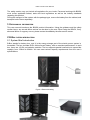
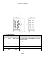
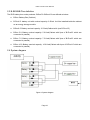
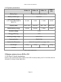
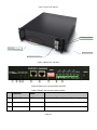
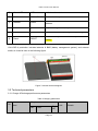
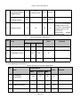
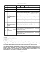
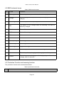
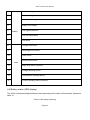
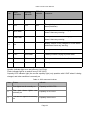
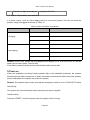
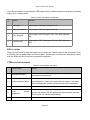
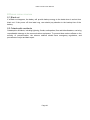
B-Box 2.5~10.0 User Manual User Manual BBox2.5~ BBox10.0 Update: 20150726 Page 3 B-Box 2.5~10.0 User Manual Version: 1.1 Copyright © BYD Company Limited. All rights reversed. Without written consent of BYD Company, any unit or individual cannot extract, copy contents of the document, or translate it into another language. Statement: This document will be subject to change without any notice. Unless otherwise agreed, the document will be used only as a guidance. All the statements in this document, information, and suggestions do not constitute any express or implied liability. Please do not hesitate to contact us for further information. BYD Company Limited TEL: 07558988 8888 FAX: 07558961 9653 Page 4 B-Box 2.5~10.0 User Manual CONTENT SAFETY PRECAUTION 1 USER MANUAL INFORMATION 2 B-BOX SYSTEM INTRODUCTION 2.1 System Brief introduction 2.2 Configuration table 2.3 B-BOX&B-Plus definition 2.4 System diagram 2.5 System parameters 3 GENERAL INTRODUCTION OF B-PLUS 2.5 3.1 B-Plus 2.5 brief introduction 3.2 Technical parameters 4 BMS FUNCTION DESCRIPTION 4.1 BMS introduction 4.2 BMS technical terms 4.3 Protection Function and warning function 4.4 Alarm items 4.5 Battery status (LED display) 4.6 Alarm information and solution 5 POWER ON Page 5 B-Box 2.5~10.0 User Manual 6 EXIT SYSTEM 7 MALFUNCTION DIAGNOSE 8 DISPOSE SPECIAL SITUATION 8.1 Black out 8.2 Catastrophic accidents Page 6 B-Box 2.5~10.0 User Manual SAFETY PRECAUTION Warning, notice, and caution Users are kindly requested to use the battery, delivered from BYD COMPANY LIMITED in strict accordance with the Datasheet and remarks included at the end of the document. BYD COMPANY LIMITED will not guarantee against any accidents occurring due to the use of the product outside the requirements mentioned in this Datasheet. WARNING Do not crush. Dispose according to safety regulations (Do not dispose in fire or water). Recharge Battery at least every 6 months (incl. when in storage). Once discharged, recharge battery within 48hours. Do not expose to temperatures above 60 ℃ (140 ℉ ). Must be grounded correctly. Do not put front panel face down. Do not short, reverse polarity or connect in series. Disconnect from power and load before maintenance. May only be used by qualified professionals. NOTICE Inadvertent operation of damaged BBOX can lead to a hazard situation that may result in serious injury due to electrical shock. The BBOX can only be operated, when it is technically faultless and in an operationally safe state. Regularly check the BBOX for visible damage. Make sure that all safety equipment is freely accessible at all time. If the BBOX is damaged, do not touch it. Please immediately contact your after sale service if a significant event message is shown on the LCD inverter. CAUTION Liion battery inside, when disassembling the system, do not intentionally short the positive (+) and negative () terminals with metallic objects. All works on system and electrical connections must be carried out by qualified personnel only. B Box provides an emergency switch that has to be used in case of emergency. A potentially hazard circumstance, such as excessive heat or electrolyte mist may occur due to incorrect operation, damage, or abuse. If the safety precautions and the warning messages described are not fully understood, or if you have any questions, please contact the after sales service for guidance. Page 7 B-Box 2.5~10.0 User Manual The safety section may not include all regulations for your locale. Personnel working with BBOX must review applicable federal, state and local regulations as well as the industry standards regarding this product. During the transport of the system with the package type, remove the battery from the cabinet, and transport both of them separately. 1 USER MANUAL INFORMATION This user manual introduces the BBOX product information. Using the guidance and the safety caution items, any normal failure actions can be done by the user. When using the BBOX, if any abnormal failure or urgency occurs, please contact immediately the after service center. 2 B-BOX SYSTEM INTRODUCTION 2.1 System Brief introduction BBox stands for battery box, and it is the energy storage part of the electric power system in household. The box includes BYD’s lithium ferrum battery, with an excellent performance. In each box, there are 1/2/3/4 pcs batteries modules. The box supports parallel connection to expand the capacity from 2.5Kwh to 80Kwh. We can meet various capacity requirements from the user´s specifications. Figure 1 External drawing Page 8 B-Box 2.5~10.0 User Manual Figure 2 Internal drawing Figure 3 Structure dimension drawing 2.2 Configuration table No . Component Name Description 1 Cabinet BBox Cabinet The outer Cabinet to install the BPlus 2.5 inside and provide DC output 2 Battery BPlus2.5 3 BMU BMU 4 Activate part D482900 Activates the inverter and the battery. 5 Emergency switch Emergency switch Cutsoff the power in emergency case. Battery module with 51.2V44Ah, BYD’s P/N is: U3A150PA. Provides communication with the external equipment. Table 1 configuration list Page 9 B-Box 2.5~10.0 User Manual 2.3 BBOX&BPlus definition The BYD battery box series products BBox5.0~BBox10.0 are defined as below: ● BBox: BatteryBox (Cabinet) ● BPlus2.5: battery unit with nominal capacity: 2.5Kwh. It will be installed inside the cabinet as an energy storage module ● BBox2.5: Battery nominal capacity: 2.5 Kwh(Cabinet with 1pcs BPlus2.5 ) ● BBox 5.0: Battery nominal capacity: 5.0 Kwh(Cabinet with 2pcs of BPlus2.5 which are connected in parallel) ● BBox 7.5: Battery nominal capacity: 7.5 Kwh(Cabinet with 3pcs of BPlus2.5 which are connected in parallel) ● BBox 10.0: Battery nominal capacity: 10.0 Kwh(Cabinet with 4pcs of BPlus2.5 which are connected in parallel) 2.4 System diagram Figure 4 System diagram Page 10 B-Box 2.5~10.0 User Manual 2.5 System parameters BBox 2.5 BBox 5.0 BBox 10.0 BBox 7.5 Battery Type Lithium Iron phosphate battery Battery module type Bplus2.5 Rated battery energy (0.2C charge &discharge at @+25 ℃ ) 2.5 Kwh 5 Kwh 7.5 Kwh 10 Kwh Output power Max 2.5 Kw Max 5Kw Max 7.5Kw Max 10 Kw Usable battery energy 2.4Kwh 4.8Kwh 7.2Kwh 9.6kwh Nominal voltage 51.2V Energy efficiency >97% Working voltage range 44.8V57.6V Communication RS485/CAN Cabinet Net Dimension Width 600* depth 600* mm height 1108 Net Weight 88 Kg 126Kg IP level 164Kg 202Kg IP20 Table2 system parameters 3 GENERAL INTRODUCTION OF B-PLUS 2.5 3.1 BPlus 2.5 brief introduction BPlus is the commercial name of BYD U3A150PA backup battery with 51.2V& 50Ah which is designed for energy storage application. Page 11 B-Box 2.5~10.0 User Manual Figure 5 BPlus 2.5 overview ① ② ③④ ⑤ ⑥ ⑦ ⑧ ⑨ Figure 6 Display and communication interface Table 3 Display and communication interface No . ① Interface Mark Function SOC LED SOC Indicates the State of charge of the battery ② RUN LED RUN Indicates the positive is in running status ③ ERR LED ERR Indicates error status Page 12 B-Box 2.5~10.0 User Manual ④ Alarm LED ARM Indicates alarm status ⑤ RJ45 terminal RS232/RS485 Communication ports ⑥ Address ADDR In case of parallel connection, it needs to be set up address. ⑦ FPC ] Dry contact application, output alarm info. ⑧ Test terminal B B+ It measures the battery voltage during testing. ⑨ Reset RESET Activate battery when no external power added battery. U3A150PA production includes batteries & BMS (battery management system), and external shells, as it can be seen in the following figure. Figure 7 Internal Structure diagram 3.2 Technical parameters 3.2.1 Charge & Discharge performance parameters Table 4 Charging parameters Requirement No . Item Min. Max. Typi cal Page 13 Unit Remark B-Box 2.5~10.0 User Manual Charge voltage (equalized charge) chargecharge) 1 Charge voltage (floating charge) 2 58.5 (protect level) 56.5 V(DC) 54.4 55.2 V(DC) Charge current 0 50 25 10 ℃ ~0 ℃ recommend charge current is 4A 0 ℃ ~10 ℃ recommend charge current is 8A. 10 ℃ ~70 ℃ recommend charge current is 25A. A Table 5 Discharging parameters Requirement No . Item 1 Unit Remark Min. Max. Typical Discharge voltage 40 51.2 V(DC) 2 Discharge current 60 25 A 3 Backup power 2560 Wh 3.2.2 Operating environment Table 6 Operating environment parameters Requirement No . Item 1 Discharging temperature 20 25 60 ℃ 2 Charging temperature 10 25 60 ℃ 3 Relative humidity 5 95 % 4 Absolute humidity 0.26 25 g/m3 Unit Min. Typical Page 14 Remark Max. B-Box 2.5~10.0 User Manual 5 Elevation 6 Cooling Do not need peripheral cooling equipment 7 IP level 20 8 Storage and Temperature(shutdow n mode) 2000 m When the storage temperature is 25 ℃ , should chargedischarge battery at least one cycle every 12 months or charge batteries according to the “NEXT CHARGE” label in package. When the storage temperature is 35 ℃ , should chargedischarge battery at least one cycle every 6 months. When the storage temperature is 45 ℃ , should chargedischarge battery at least one cycle every 3 months. 9 10 Normal Maintenance(shutdow n mode) Low maintenance voltage Stored at room temperature, should chargedischarge battery at least one cycle every 12 months. The battery will exit the system automatically due to low voltage protection.If the temperature is 25ºC need to be charged within 30days. The battery will exit the system automatically due to low voltage protection.If the temperature is 45ºC need to be charged within 7days. 4 BMS FUNCTION DESCRIPTION 4.1 BMS introduction The BMS is an important component that has effect on both, battery protection and monitor. In the longterm process of using batteries, the consistence difference of battery pack, may causes voltage difference and SOC difference from the cell. The cell holding higher SOC may be easily fully charged and cell keeping lower SOC may cause over discharge and lead to cell failure. Over charge/discharge will cause a series of problems, such as, increase of resistance, lithium ion separation, power degradation etc. As well as decrease of the efficiency of charge/discharge, shorten the cycle life and cause potential risk. So, the BMS avoids over charge/discharge of the battery pack or cell unit in order to use batteries in the best way. Page 15 B-Box 2.5~10.0 User Manual 4.2 BMS technical terms Table 7 BMS technical terms No. Terms comment 1 Discharge The battery returns power to the load or other equipment 2 Charge The battery gets the power from power supply(such as DC charger) 3 Full charged The battery has been fully charged, SOC is 100%. 4 Idle The battery is not on charge status nor discharge, and has not been fully charged. 5 Shutdown mode Power off. 6 SOC Status of the charge. 7 SW Software. 8 HW Hardware. 9 Battery voltage The voltage between B+/B. 10 Pack voltage The voltage between P+/P. 11 Cell voltage Single cell voltage. 12 Failure The battery or BMS are broken, need to change to a new unit. 13 Alarm The battery will stop charging or discharging immediately. 14 Protect The battery stops charging or discharging (e.g. cell is under voltage), and it is resumed. 4.3 Protection Function and warning function The protection function works as described below: Table 8 protection function list No. Function Page 16 B-Box 2.5~10.0 User Manual 1 PACK overvoltage protection 2 Battery overvoltage protection 3 Battery under voltage protection 4 Cell over charge protection 5 Cell over discharge protection 6 Over current Protection of charging 7 Over current Protection of discharging 8 Short circuit protection 9 Reverse connect protection 10 High temperature Protection 11 Low temperature Protection 12 LED Display 13 Communication Function 14 Equalization Function 15 Capacity Calculation Remarks: The BMS will turn off in the following conditions: ✓ ✓ ✓ Cell over discharge protection Battery under voltage protection Discharge over current protection 4.4 Alarm items Table 9 Alarm list No . Type Warning items Page 17 B-Box 2.5~10.0 User Manual 1 Cell overvoltage 2 Cell lowvoltage 3 4 Battery over voltage Battery lowvoltage 5 Cell high temperature Battery 6 Cell low temperature 7 Cell failure 8 Charge overcurrent 9 Discharge over current 10 Short circuit 11 Reverse connection BMS 12 Major loop failure (reserve) 13 Voltage sampling failure 14 Temperature Sampling failure 15 Current Sampling failure (reserve) 4.5 Battery status (LED display) The LEDs on the panel displays different cases depending on the status of the batteries, please see table 10. Table 10 LED display explaining Page 18 B-Box 2.5~10.0 User Manual No. Work indication Warning indication ERROR indicatio n Indication RUN ALARM ERROR 1 OFF OFF OFF The battery module is in unactivated state(Shutdown) 2 Slow flash Battery module is on charging status and doesn’t have any warning. 3 Fast Flash Battery module is on discharging status and doesn’t have any warning 4 On Battery module is fully charged or on idle status and doesn’t have any warning. 5 OFF ON Battery module is on protection status. 6 OFF Slow flash Battery module is trying to power down 7 ON ON Battery module needs to be calibrated 8 OFF OFF ON Battery module is on failure status Remark: Sparkle: Indicator light is on and off every 1s (0.5Hz). Flash: indicator light is on and off every 0.25s (2HZ) Capacity LED indicator light (the current capacity light) only sparkles with 0.5HZ when it’s being charged, and other condition is normally on. Table 11 SOC status and indicate Item Status Indicate 1 Four lights are all normally on Capacity is 100%75% 2 The last three lights are normally on Capacity is 74%50% 3 The last two lights are normally on Capacity is 49%25% Page 19 B-Box 2.5~10.0 User Manual 4 The last one light is normally on Capacity is 24%0% 4.6 Alarm information and solution If a failure occurs, such as overvoltage protect or overcurrent protect, the user can solve the problem using the suggestion shown on Table 12: Table 12 Alarm information and solution Status Charging Alarm info. LED display Pack overvoltage ALM LED on Overcurrent ALM LED on Overtemp. ALM LED on Overcurrent ALM LED on Overtemp. ALM LED on Batteries overdischarge ALM LED on Cell overdischarge ALM LED on Discharging Remark: When under voltage warning happens on the battery or cell, ALM LED will be on, and the battery will exit the system 1 minute later. If the alarm continues, please contact with the after sales service staff. 5 POWER ON When the installation has been finished (please refer to the installation guidance), the operator should check the cable connections in detail, and make sure that all the cables have been properly placed. Afterwards, the operator can power the system. Remark: The operator has to make sure that the emergency switch is not on “PUSH INTO” status. Grid activity: The system will run automatically when external power input is applied. Handle activity: Press the “RESET” on the front panel, then the system will be running. Page 20 B-Box 2.5~10.0 User Manual Once that the system is activated the LED lights will be in different status according to the battery status, as it is shown below: Table 13 Alarm information and solution Ite m Status Indicate 1 Charging Green light is blinking, Red light is OFF 2 Charge protection Green light is ON, Red light is blinking 3 Fully charged Green light is ON, Red light is OFF. ALL SOC lights are ON 4 Failure mode Green light is OFF, Red light is ON. ALL SOC lights are OFF 6 EXIT SYSTEM When the user wants to stop the system he can press the “Reset” button on the front panel. Then, the battery can be safely taken out of the system. Another way is to press the emergency switch, then the BBox will be cut off from the external equipment. 7 MALFUNCTION DIAGNOSE Table 14 Normal failure and action No . Failure item Action 1 Malfunction alarm When the “Alarm” LED is lighting continuously, please contact the after service personal. 2 Communication failure If there is a failure on RS485/CAN communication, it could be solved as below. Check the communication cables; if the alarm does not disappear, please contact the after service personal. 3 Failure protection Please contact the after service personal. 4 Over protection It is a normal case during charge, when over current protection occurs, the yellow LED will lighting until the protection releases. This function will release automatically. 5 Other failure current Please contact the after service personal. Page 21 B-Box 2.5~10.0 User Manual 8 DISPOSE SPECIAL SITUATION 8.1 Black out If a Black out happens, the battery will provide backup energy to the loads when is a short time black out. If the power off time lasts long, user should pay attention to the backup time of the battery. 8.2 Catastrophic accidents Catastrophic accidents, including lightning, floods, earthquakes, fires and other disasters, can bring unpredictable damage to the communications equipment. To prevent these serious effects on the security of communication, the telecom stations should have emergency regulations, and procedures of major accident repair. Page 22 B-Box 2.5~10.0 User Manual Contact us : China BYD LITHIUM BATTERY Co.,LTD Customer Service Mailbox: eubatterygrp @byd.com Telephone:+86 0755 89888888 Address: No.1,Baoping Road,Baolong lndustrial Town Longgang Shenzhen, 518116, P.R.China Germany Company name :EFT Energy for tomorrow Customer Service Mailbox: kontakt@eftsystems.de Telephone : +496996759811 Address : Buchenstraße, 37 Lohr a. Main 97816 Germany. Page 23