1
MITSUBISHI ELECTRIC
MELSEC WS Series
Safety Controller
User's Manual
WS0-GETH
Art. no.: SH(NA)-080857
02032010
Version B
MITSUBISHI ELECTRIC
INDUSTRIAL AUTOMATION
This document is protected by the law of copyright, whereby all rights established
therein remain with the company Mitsubishi Electric Corporation. Reproduction of
this document or parts of this document is only permissible within the limits of the
legal determination of Copyright Law. Alteration or abridgement of the document is
not permitted without the explicit written approval of the company Mitsubishi Electric
Corporation.
Precautions regarding warranty and specifications
MELSEC-WS series products are jointly developed and manufactured by Mitsubishi
and SICK AG, Industrial Safety Systems, in Germany.
Note that there are some precautions regarding warranty and specifications of
MELSEC-WS series products.
<Warranty>
The gratis warranty term of the product shall be for one (1) year after the date of
delivery or for eighteen (18) months after manufacturing, whichever is less.
The onerous repair term after discontinuation of production shall be for four (4)
years.
Mitsubishi shall mainly replace the product that needs a repair.
It may take some time to respond to the problem or repair the product depending
on the condition and timing.
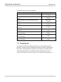
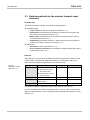
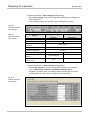
<Specifications>
General specifications of the products differ.
MELSEC-WS
*1
Operating ambient temperature
-25 to 55°C
Operating ambient humidity
10 to 95%RH
Storage ambient temperature
Storage ambient humidity
-25 to 70°C
10 to 95%RH
MELSEC-Q,
MELSEC-QS
0 to 55°C
5 to 95%RH
*2
-25 to 75°C
5 to 95%RH
*1 When the WS0-GCC100202 is included in the system, operating ambient
temperature will be 0 to 55 °C.
*2 For the MELSEC-QS series programmable controller, storage ambient
temperature will be -40 to 75°C.
EMC standards that are applicable to the products differ.
MELSEC-WS
EMC standards
EN61000-6-2, EN55011
MELSEC-Q,
MELSEC-QS
EN61131-2
SAFETY PRECAUTIONS
(Read these precautions before using this product.)
Before using this product, please read this manual, the relevant manuals, and the safety standards carefully
and pay full attention to safety to handle the product correctly.
The precautions given in this manual are concerned with installation of this product and wiring with the
external application only.
For the safety precautions of the MELSEC-WS safety controller system, refer to the user's manual for the
CPU module used.
In this manual, the safety precautions are classified into two levels: “
WARNING” and “
CAUTION”.
WARNING
Indicates that incorrect handling may cause hazardous conditions, resulting
CAUTION
Indicates that incorrect handling may cause hazardous conditions, resulting
in death or severe injury.
in minor or moderate injury or property damage.
Under some circumstances, failure to observe the precautions given under “
CAUTION” may lead to
serious consequences.
Observe the precautions of both levels because they are important for personal and system safety.
Make sure that the end users read this manual and then keep the manual in a safe place for future
reference.
[Design Precautions]
WARNING
The Ethernet interface module is not suitable for operation on a safety fieldbus.
The Ethernet interface module only generates non-safety-related fieldbus data (status bytes) for control
and diagnostics purposes.
Do not use non-safe data from an Ethernet interface module for safety related applications.
With the Ethernet interface module it is possible to integrate non-safe data into the logic editor such
that the safety function of the MELSEC-WS safety controller is compromised. Never implement the
Ethernet interface module into a MELSEC-WS safety controller without having this danger checked by
a safety specialist.
1
CAUTION
Do not install the control lines or communication cables together with the main circuit lines or power cables.
Keep a distance of 100 mm or more between them.
Failure to do so may result in malfunction due to noise.
The MELSEC-WS safety controller fulfils the requirements of Class A (industrial applications) in
accordance with the “Interference emission” basic specifications.
The MELSEC-WS safety controller is therefore only suitable for use in an industrial environment and not for
private use.
[Installation Precautions]
CAUTION
Use the MELSEC-WS safety controller in an environment that meets the general specifications in the user’s
manual for the CPU module used. Failure to do so may result in electric shock, fire, malfunction, or damage
to or deterioration of the product.
Latch the module onto the DIN rail. Incorrect mounting may cause malfunction, failure or drop of the module.
To ensure full electromagnetic compatibility (EMC), the DIN mounting rail has to be connected to functional
earth (FE).
Ensure that the earthling contact is positioned correctly. The earthling spring contact of the module must
contact the DIN rail securely to allow electrical conductivity.
Additionally connect all network cable shields directly at the control cabinet entrance to a common FE
ground line.
Tighten the screw within the specified torque range.
Undertightening can cause drop of the screw, short circuit or malfunction.
Overtightening can damage the screw and/or module, resulting in drop, short circuit, or malfunction.
Shut off the external power supply for the system in all phases before mounting or removing the module.
Failure to do so may result in damage to the product.
Do not directly touch any conductive part of the module.
Doing so can cause malfunction or failure of the module.
The MELSEC-WS safety controller is only suitable for mounting in a control cabinet with at least IP 54
degree of protection.
Failure to meet the installation method may cause the module to fail or malfunction due to the deposition of
dust or the adhesion of water.
Make sure that the connection of the Ethernet interface module cannot lead to hazardous situations
during installation.
Ensure that the connection of the Ethernet dedicated cables and power cables cannot lead to a hazardous
situation when implementing the unit on to the MELSEC-WS safety controller and Ethernet network.
Prevent unintended start-up of equipment during connection of a Ethernet interface module. Failure to do so
may cause the system to malfunction.
2
[Wiring Precautions]
CAUTION
Switch the entire machine/system off line.
The system could start up unexpectedly while you are connecting the devices.
Connectors for external devices must be crimped or pressed with the tool specified by the manufacturer,
or must be correctly soldered. Incomplete connections could result in short circuit, fire, or malfunction.
Connect the connectors to the module securely.
Failure to do so may cause malfunction due to poor contact.
Place the cables in a duct or clamp them.
If not, dangling cable may swing or inadvertently be pulled, resulting in damage to the module or cables
or malfunction due to poor contact.
Tighten the terminal screw within the specified torque range.
Undertightening can cause short circuit or malfunction.
Overtightening can damage the screw and/or module, resulting in drop, short circuit, or malfunction.
When disconnecting the cable from the module, do not pull the cable by the cable part.
When disconnecting the cable with connector from the module, hold the connector part.
When disconnecting the cable connected to a terminal block, loosen the terminal screws first.
Failure to do so may result in damage to the module or cable or malfunction.
Prevent foreign matter such as dust or wire chips from entering the module.
Such foreign matter can cause a fire, failure, or malfunction.
3
CONDITIONS OF USE FOR THE PRODUCT
(1) Although MELCO has obtained the certification for Product's compliance to the international safety
standards IEC61508, EN954-1/ISO13849-1 from TUV Rheinland, this fact does not guarantee that
Product will be free from any malfunction or failure. The user of this Product shall comply with any and all
applicable safety standard, regulation or law and take appropriate safety measures for the system in
which the Product is installed or used and shall take the second or third safety measures other than the
Product. MELCO is not liable for damages that could have been prevented by compliance with any
applicable safety standard, regulation or law.
(2) MELCO prohibits the use of Products with or in any application involving, and MELCO shall not be liable
for a default, a liability for defect warranty, a quality assurance, negligence or other tort and a product
liability in these applications.
1) power plants,
2) trains, railway systems, airplanes, airline operations, other transportation systems,
3) hospitals, medical care, dialysis and life support facilities or equipment,
4) amusement equipments,
5) incineration and fuel devices,
6) handling of nuclear or hazardous materials or chemicals,
7) mining and drilling,
8) and other applications where the level of risk to human life, health or property are elevated.
4
REVISIONS
*The manual number is given on the bottom left of the back cover.
Print date
*Manual number
Revision
September, 2009
SH(NA)-080857ENG-A
First edition
March, 2010
SH(NA)-080857ENG-B
Correction of errors in writing
Japanese manual version SH-080854-B
This manual confers no industrial property rights or any rights of any other kind, nor does it confer any patent licenses.
Mitsubishi Electric Corporation cannot be held responsible for any problems involving industrial property rights which may
occur as a result of using the contents noted in this manual.
© 2009 MITSUBISHI ELECTRIC CORPORATION
5
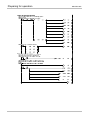
CONTENTS
SAFETY PRECAUTIONS........................................................................................... 1
CONDITIONS OF USE FOR THE PRODUCT ........................................................... 4
REVISIONS ................................................................................................................ 5
CONTENTS ................................................................................................................ 6
GENERIC TERMS AND ABBREVIATIONS................................................................ 8
1.
About this document................................................................................. 9
1.1
Function of this document......................................................................... 9
1.2
MELSEC-WS manuals ............................................................................. 9
1.3
Target group............................................................................................ 10
1.4
Depth of information ............................................................................... 11
1.5
Scope...................................................................................................... 11
1.6
Abbreviations used ................................................................................. 11
1.7
Symbols used ......................................................................................... 11
2.
On safety ................................................................................................ 12
2.1
Qualified safety personnel ...................................................................... 12
2.2
Correct use ............................................................................................. 12
2.3
Environmental protection ........................................................................ 14
2.3.1
Disposal .............................................................................................. 14
2.3.2
Material separation ............................................................................. 14
3.
Ethernet interface module ...................................................................... 15
3.1
Overview ................................................................................................. 15
3.1.1
Interfaces and operation ..................................................................... 15
3.2
Mounting/Dismantling ............................................................................. 17
3.2.1
Steps for mounting the modules ......................................................... 17
3.2.2
Steps for dismantling the modules...................................................... 19
3.3
Electrical installation ............................................................................... 20
3.4
First configuration steps.......................................................................... 20
3.4.1
Establishing a connection between MELSEC-WS safety controller
and PC ................................................................................................ 20
3.4.2
Assignment of an IP address .............................................................. 22
3.4.3
Configuration of the Ethernet interface module .................................. 24
3.4.4
Transfer of a configuration .................................................................. 25
3.4.5
Verification of a configuration.............................................................. 26
3.4.6
Upload of a configuration .................................................................... 26
3.5
Features of the Ethernet interface module ............................................. 27
3.5.1
TCP/IP configuration interface ............................................................ 27
3.5.2
Ethernet TCP/IP socket interface........................................................ 31
3.5.3
TCP/IP process image example ......................................................... 39
4.
Data sets................................................................................................. 42
4.1
Data transmitted into the network (network input data sets) .................. 43
4.1.1
Logic results ........................................................................................ 45
4.1.2
Module and EFI input and output values ............................................ 45
4.1.3
Routing of data from a second network .............................................. 45
4.1.4
Configuration checksums (CRCs) ...................................................... 46
4.1.5
Error and status information of the modules....................................... 46
4.2
Data received from the network (network output data sets) ................... 49
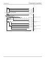
6
4.3
4.4
4.4.1
4.4.2
4.4.3
4.4.4
4.5
4.5.1
4.5.2
4.6
5.
6.
6.1
6.2
6.3
6.4
6.5
7.
7.1
7.2
8.
8.1
8.2
8.3
8.3.1
8.3.2
8.3.3
8.3.4
8.3.5
8.3.6
8.3.7
8.3.8
9.
9.1
9.2
9.3
10.
10.1
7
Default settings for the input data set 1 .................................................. 50
Customizing the input data set 1 (MELSEC-WS to Ethernet) ................ 51
The toolbar .......................................................................................... 52
Available data area ............................................................................. 53
Network Module Data area ................................................................. 54
Tag names area .................................................................................. 54
Tag names for incoming data (Ethernet to MELSEC-WS) ..................... 55
Saving and loading a configuration..................................................... 57
Importing and exporting a configuration ............................................. 57
Monitoring the data set online................................................................. 58
Troubleshooting ...................................................................................... 59
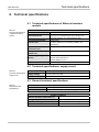
Technical specifications .......................................................................... 61
Technical specifications of Ethernet interface module............................ 61
Technical specifications, supply circuit ................................................... 61
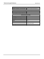
General technical specifications ............................................................. 61
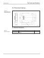
Dimensional drawings............................................................................. 63
Module information ................................................................................. 63
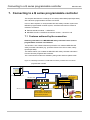
Connecting to a Q series programmable controller................................ 64
Features achieved by the connection..................................................... 64
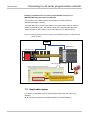
Applicable system ................................................................................... 65
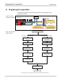
Preparing for operation........................................................................... 66
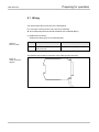
Wiring...................................................................................................... 67
Wiring precautions .................................................................................. 69
Sample programs ................................................................................... 70
Parameter configuration: polling mode
(input data set reading/output data set writing)................................... 72
Sample program: polling mode (input data set reading)..................... 79
Monitoring data with GX Developer: polling mode
(input data set reading) ....................................................................... 88
Sample program: polling mode (output data set writing) .................... 89
Monitoring data with Setting and Monitoring Tool: polling mode
(output data set writing) ...................................................................... 95
Parameter configuration: auto update mode ...................................... 96
Sample program: auto update mode .................................................. 99
Monitoring data with GX Developer: auto update mode................... 106
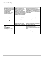
Troubleshooting when Ethernet interface module is connected to Q
series programmable controller ............................................................ 107
When data cannot be normally exchanged .......................................... 107
When data cannot be exchanged in polling mode (reading/writing)..... 108
When data cannot be exchanged in auto update mode ....................... 110
Annex..................................................................................................... 111
SICK contact ..........................................................................................111
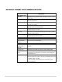
GENERIC TERMS AND ABBREVIATIONS
Generic
Description
term/abbreviation
WS0-MPL
Abbreviation for the WS0-MPL00201 MELSEC-WS safety controller
memory plug
WS0-CPU0
Abbreviation for the WS0-CPU000200 MELSEC-WS safety
controller CPU module
WS0-CPU1
Abbreviation for the WS0-CPU130202 MELSEC-WS safety
controller CPU module
WS0-XTIO
Abbreviation for the WS0-XTIO84202 MELSEC-WS safety
controller safety I/O combined module
WS0-XTDI
Abbreviation for the WS0-XTDI80202 MELSEC-WS safety
controller safety input module
WS0-4RO
Abbreviation for the WS0-4RO4002 MELSEC-WS safety controller
safety relay output module
WS0-GETH
Abbreviation for the WS0-GETH00200 MELSEC-WS safety
controller Ethernet interface module
CPU module
Generic term for the WS0-CPU0 and WS0-CPU1
Safety I/O module
Generic term for the WS0-XTIO and WS0-XTDI
Ethernet interface
Another name for the WS0-GETH
module
Network module
Generic term for the WS0-GETH and WS0-GCC1
Q series
Abbreviation for the Mitsubishi MELSEC-Q series programmable
programmable
controller
controller
QJ71E71-100
Abbreviation for the MELSEC QJ71E71-100 Ethernet module
Built-in Ethernet port
Generic term for the Q03UDEHCPU, Q04UDEHCPU,
QCPU
Q06UDEHCPU, Q10UDEHCPU, Q13UDEHCPU, Q20UDEHCPU,
and Q26UDEHCPU
GX Developer
Generic product name for the SWnD5C-GPPW-E,
SWnD5C-GPPW-EA, SWnD5C-GPPW-EV, and SWnD5C-GPPW-EVA
(“n” indicates version 4 or later.)
“-A” and “V” indicate volume license product and version upgrade
product, respectively.
8
About this document
MELSEC-WS
1. About this document
Please read the SAFETY PRECAUTIONS, Chapter 1 and Chapter 2 carefully
before working with this documentation and the MELSEC-WS safety controller
Ethernet interface modules.
1.1 Function of this document
This manual only applies in conjunction with the other MELSEC-WS manuals (see
Section 1.2) and instructs the technical staff of the machine manufacturer and/or of
the machine operator on safe mounting, adjustment, electrical installation,
commissioning as well as operation and maintenance of the Ethernet interface
module.
The manual does not provide instructions for operating the machine in which the
MELSEC-WS safety controller and Ethernet interface module are, or will be,
integrated. Information of this kind will be found in the manuals for the machine.
1.2 MELSEC-WS manuals
For the MELSEC-WS safety controller there are three manuals with clearly
distinguished fields of application as well as User’s Manuals (Hardware) for each
module.
This manual describes the Ethernet interface modules and their functions in
detail.
The User’s Manuals (Hardware) are enclosed with each MELSEC-WS module.
They inform on the basic technical specifications of the modules and contain
simple mounting instructions. Use the User’s Manuals (Hardware) when
mounting MELSEC-WS safety controllers.
The Safety Controller User’s Manual describes all the MELSEC-WS modules and
their functions in detail. Use the manual in particular to configure MELSEC-WS
safety controllers.
The Safety Controller Setting and Monitoring Tool Operating Manual describes the
software-supported configuration and parameterization of the MELSEC-WS
safety controllers. In addition, the manual contains the description of the
diagnostics functions that are important for operation and detailed information for
the identification and elimination of errors. Use the manual in particular for the
configuration, commissioning and operation of MELSEC-WS safety controllers.
9
About this document
MELSEC-WS
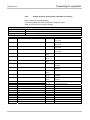
The following shows the relevant manuals.
Title
Safety Controller User’s Manual
Number
WS-CPU-U-E
(13JZ32)
Safety Controller Ethernet Interface Module User's
Manual
Safety Controller CC-Link Interface Module User's
Manual
Safety Controller Setting and Monitoring Tool Operating
Manual
Safety Controller CPU Module User's Manual
(Hardware)
Safety Controller Safety I/O Module User's Manual
(Hardware)
Safety Controller Safety Relay Output Module User's
Manual (Hardware)
Safety Controller Ethernet Interface Module User's
Manual (Hardware)
Safety Controller CC-Link Interface Module User's
Manual (Hardware)
WS-ET-U-E
(13JZ33)
WS-CC-U-E
(13JZ45)
SW1DNN-WS0ADR-B-O-E
(13JU67)
WS-CPU-U-HW
(13J200)
WS-IO-U-HW
(13J201)
WS-SR-U-HW
(13J202)
WS-ET-U-HW
(13J203)
WS-CC-U-HW
(13J209)
1.3 Target group
This manual is addressed to planning engineers, machine designers and the
operators of systems in which a MELSEC-WS safety controller is integrated and
who want to exchange data with a fieldbus (a controller) via a network module.
It also addresses people who integrate the network module into a machine,
commission it initially or who are in charge of servicing and maintaining the unit.
10
About this document
MELSEC-WS
1.4 Depth of information
This manual contains information on the Ethernet interface module in the following
subjects:
mounting
implementation into a network
configuration via Setting and Monitoring Tool
data transfer to and from the network
status information, planning and related mapping
part numbers
ATTENTION
Note
Warning!
Pay attention to the safety notes and safety measures on the Ethernet interface
module!
For the acquisition of Setting and Monitoring Tool, please contact your local
Mitsubishi representative.
1.5 Scope
This manual applies to the WS0-GETH Ethernet interface module.
This document is the original manual.
1.6 Abbreviations used
EFI
Enhanced Function Interface
1.7 Symbols used
Note
Red,
zRed,
{Green
Notes provide special information on the device.
LED symbols describe the state of a diagnostics LED. Examples:
zRed
Red
The red LED is illuminated constantly.
The red LED is flashing.
{Green The green LED is off.
⇒ Action
ATTENTION
11
Instructions for taking action are shown by an arrow. Read carefully and follow the
instructions for action.
Warning!
An “ATTENTION” indicates an actual or potential risk or health hazard. They are
designed to help you to prevent accidents.
Read carefully and follow the attention notices!
On safety
MELSEC-WS
2. On safety
This chapter deals with your own safety and the safety of the equipment operators.
Please read this chapter carefully before working with an Ethernet interface
module.
2.1 Qualified safety personnel
The Ethernet interface module may only be installed, commissioned and serviced
by qualified safety personnel.
Qualified safety personnel are defined as persons who…
have undergone the appropriate technical training
and
have been instructed by the responsible machine operator in the operation of the
machine and the current valid safety guidelines
and
have access to the manuals of the Ethernet interface module and safety controller
and have read and familiarised themselves with them.
2.2 Correct use
The Ethernet interface module can only be operated with a MELSEC-WS safety
controller.
The Ethernet interface module does not have a dedicated voltage supply.
ATTENTION
The Ethernet interface module is not suitable for operation on a safety
fieldbus!
The Ethernet interface module only generates non-safety-related fieldbus data
(status bytes) for control and diagnostics purposes.
Do not use non-safe data from an Ethernet interface module for safety
related applications!
With the Ethernet interface module it is possible to integrate non-safe data into the
logic editor such that the safety function of the MELSEC-WS safety controller is
compromised. Never implement the Ethernet interface module into a
MELSEC-WS safety controller without having this danger checked by a safety
specialist.
The Ethernet interface module may only be used by qualified safety personnel and
only on the machine where they have been installed and initialized by qualified
safety personnel in accordance with the manual.
12
On safety
MELSEC-WS
ATTENTION
Note
ATTENTION
13
Pay attention to the safety notes and safety measures on the Ethernet
interface module!
If the device is used for any other purposes or modified in any way - also during
mounting and installation - any warranty claim against Mitsubishi Electric
Corporation shall become void.
When mounting, installing and using the Ethernet interface module, observe the
standards and directives applicable in your country.
The national/international rules and regulations apply to the installation,
commissioning, use and periodic technical inspection of the MELSEC-WS safety
controller, in particular:
– EMC directive 2004/108/EC,
– Provision and Use of Work Equipment Directive 89/655/EC,
– the work safety regulations/safety rules.
This manual must be made available to the operator of the machine where the
MELSEC-WS safety controller is used. The machine operator is to be instructed in
the use of the device by qualified safety personnel and must be instructed to read
the manual.
Since an Ethernet interface module is powered from the CPU module, connect a
Class 2 power supply or a Class 2 transformer in accordance with UL310 or
UL1585 to the CPU module.
The MELSEC-WS safety controller fulfils the requirements of Class A (industrial
applications) in accordance with the “Interference emission” basic specifications.
The MELSEC-WS safety controller is therefore only suitable for use in an
industrial environment and not for private use.
On safety
MELSEC-WS
2.3 Environmental protection
The Ethernet interface module has been designed to minimise environmental
impact. It uses only a minimum of power and natural resources.
At work, always act in an environmentally responsible manner.
2.3.1
Disposal
Disposal of unusable or irreparable devices should always occur in accordance with
the applicable country-specific waste-disposal regulations (e.g. European Waste
Code 16 02 14).
2.3.2
ATTENTION
Material separation
Material separation may only be performed by qualified safety personnel!
Exercise care when disassembling the devices. The danger of injury is present.
Before you can turn over the devices for environmental-friendly recycling, you must
separate the different materials of the Ethernet interface module from one another.
Separate the housing from the remaining components (especially the PCB).
Send the separated components to the corresponding recycling centers (see the
following table).
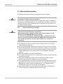
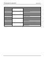
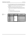
Table 1:
Overview of disposal by
components
Component
Product
Disposal
Electronics recycling
Housing
PCBs, cables, plugs and electrical
connection pieces
Packaging
Paper/cardboard recycling
Cardboard, paper
14
Ethernet interface module
MELSEC-WS
3. Ethernet interface module
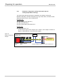
This chapter describes the Ethernet interface module (WS0-GETH).
3.1 Overview
The Ethernet interface module is connected to Setting and Monitoring Tool, a
MELSEC programmable controller, and PC via TCP/IP. The module can:
Exchange configuration data and programs of a MELSEC-WS safety controller
by connecting to Setting and Monitoring Tool via TCP/IP.
Exchange non-safety related data by connecting to an external application (e.g.
MELSEC programmable controller, PC) via TCP/IP.
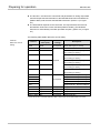
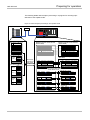
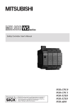
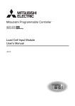
3.1.1
Interfaces and operation
The Ethernet interface module is equipped with an integrated three-port switch for
connection with the Ethernet network. Two RJ45 sockets are available for the
connection. The switch functionality allows the Ethernet interface module to be
used for connection to another Ethernet component (e.g. connection to a notebook)
without having to interrupt the Ethernet connection to the network. (One IP address
can be configured.)
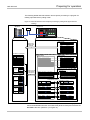
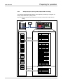
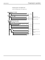
Figure 1:
Interfaces and display
elements of the
WS0-GETH
15
Ethernet interface module
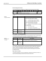
Table 2:
Meaning of the LED
displays
MELSEC-WS
LED
PWR
Meaning
{
No power supply
z Green
Power supply switched on
LINK/ACT 1
{
No Ethernet connection
LINK/ACT 2
z Green
Ethernet connection active, no data transmission
Green
MS
Ethernet connection active, data transmission
No power supply or immediately after the module start
{
z Green
Executing (live process data from/to CPU)
Green
Idle
Red
1 Hz: Configuring/configuration required
2 Hz: Critical fault on Ethernet interface module
z Red
Red/Green
Critical fault on another module
Executing, but Ethernet communication not established or
faulty
Note
Error elimination is described in Chapter 5.
Power-up sequence
On power up, the following LED test sequence is performed:
LED MS { Off for 6 s.
LED MS z Red for 0.25 s.
LED MS z Green for 0.25 s.
LED MS { Off
16
Ethernet interface module
MELSEC-WS
3.2 Mounting/Dismantling
This chapter describes the mounting of the Ethernet interface module.
ATTENTION
Make sure that the connection of the Ethernet interface module cannot lead
to hazardous situations during installation!
Ensure that connecting an Ethernet interface module cannot lead to a hazardous
situation when implementing the unit on to the MELSEC-WS safety controller and
Ethernet network. Prevent unintended start-up of equipment during connection of
an Ethernet interface module.
3.2.1
ATTENTION
Steps for mounting the modules
The MELSEC-WS safety controller is only suitable for mounting in a control
cabinet with at least IP 54 degree of protection.
While supply voltage is applied, modules must not be plugged to nor be
removed from the MELSEC-WS safety controller.
To ensure full electromagnetic compatibility (EMC), the DIN mounting rail
must be connected to functional earth (FE). Additionally connect all network
cable shields directly at the control cabinet entrance to a common FE
ground line.
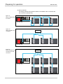
In a MELSEC-WS safety controller, the WS0-CPU0 or WS0-CPU1 module is
positioned at the extreme left.
The two optional network modules follow directly to the right of the CPU module.
Connect further MELSEC-WS safety I/O modules (e.g. WS0-XTIO or WS0-XTDI)
onto the right side of the network modules and any additional safety relay output
modules (WS0-4RO) to the extreme right of the entire MELSEC-WS safety
controller.
Mount the modules in accordance with EN 50274.
The modules are located in a 22.5 mm wide modular system for 35 mm DIN rails
according to EN 60715.
Ensure that suitable ESD protective measures are taken during mounting.
Otherwise the FLEXBUS+ backplane bus may be damaged.
The connection between the modules is effected by means of the plug connection
integrated in the housing. Take into account that, when replacing a module, the
MELSEC-WS modules have to be pushed approx. 10 mm apart before the
corresponding module can be removed from the DIN rail.
Take suitable measures to ensure that foreign matter does not penetrate the
connector openings, in particular that of the memory plug.
17
Ethernet interface module
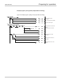
MELSEC-WS
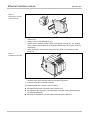
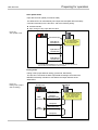
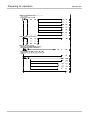
Figure 2:
Mounting the module
onto the DIN rail
2)
1)
3)
⇒ Make sure that the voltage supply of the MELSEC-WS safety controller is
switched off.
⇒ Hang the device onto the DIN rail (1)).
⇒ Ensure that the earthing spring contact is positioned correctly (2)). The earthing
spring contact of the module must contact the DIN rail securely to allow electrical
conductivity.
⇒ Latch the module onto the DIN rail by pressing it lightly in the direction of the
arrow (3)).
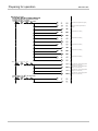
Figure 3:
Installing the end clips
⇒ If there are several modules, slide the modules together individually in the
direction of the arrow until the side plug connection latches in.
⇒ Install the end clips on the right and left.
The following steps are necessary after mounting:
Complete the electrical connections (See Section 3.3.)
Configuration (See Section 3.4 and the Safety Controller Setting and Monitoring
Tool Operating Manual.)
Checking the installation (see the Safety Controller User’s Manual.)
18
Ethernet interface module
MELSEC-WS
3.2.2
Steps for dismantling the modules
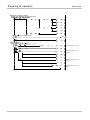
Figure 4:
Disconnecting the plug
connections
⇒ Disconnect the cables and remove the end clips.
⇒ If there are several modules, slide the modules away from each other
individually in the direction of the arrow until the side plug connection is
separated.
Figure 5:
Removing modules
from the DIN rail
1)
2)
⇒ Press the module downwards at the rear (1)) and remove it from the DIN rail in
the direction of the arrow while keeping it pressed down (2)).
19
Ethernet interface module
MELSEC-WS
3.3 Electrical installation
ATTENTION
Switch the entire machine/system off line!
The system could start up unexpectedly while you are connecting the devices.
Note
The Ethernet interface module fulfills the EMC requirements in accordance with
the basic specification EN 61000-6-2 for industrial use.
To ensure full electromagnetic compatibility (EMC), the mounting rail has to be
connected to functional earth (FE).
The control cabinet or assembly casing of the MELSEC-WS safety controller
must comply at least with enclosure rating IP 54.
Mount the modules in accordance with EN 50274.
Electrical installation in accordance with EN 60204-1
The voltage supply of the devices must be capable of buffering brief mains
voltage failures of 20 ms as specified in EN 60204-1.
The voltage supply has to fulfill the regulations for extra-low voltages with safe
separation (SELV, PELV) in accordance with EN 60664 and DIN 50178
(equipment of electrical power installation with electronic devices).
Ensure that all the modules of the MELSEC-WS safety controller, the connected
protective devices as well as the voltage supplies are connected with the same
earth (GND). The GND of the RS-232 interface is connected internally to the
GND of the supply of the CPU module (A2).
Connect all fieldbus and Ethernet cable shields directly at the control cabinet
entrance to the functional earth (FE).
3.4 First configuration steps
This chapter describes the basic steps you have to perform for the configuration of
the Ethernet interface module:
Establish a first connection between the MELSEC-WS safety controller and a
PC or laptop.
Upload or transfer of a configuration
Verification of a configuration
3.4.1
⇒
⇒
⇒
⇒
Establishing a connection between MELSEC-WS safety controller
and PC
Connect a PC or notebook to the RS-232 interface of the CPU module.
Power on the MELSEC-WS safety controller.
Open the Setting and Monitoring Tool installed on the PC.
Click on Com Settings to ensure the correct communication interface has been
selected. The following dialog appears:
20
MELSEC-WS
Ethernet interface module
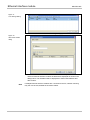
Figure 6:
Com Settings dialog
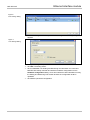
⇒ To edit the settings click on the pencil icon to the right. The following dialog
appears:
Figure 7:
Com Settings dialog
⇒ Modify the settings if required.
⇒ Click OK. The dialog closes.
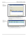
⇒ Click on Connect. The Setting and Monitoring Tool will search for connected
MELSEC-WS safety controller and load the hardware configuration into the
Hardware configuration dialog. Once all modules have been identified correctly,
the Setting and Monitoring Tool will ask whether the configuration shall be
uploaded.
⇒ Click Yes to upload the configuration.
21
Ethernet interface module
MELSEC-WS
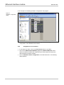
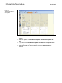
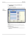
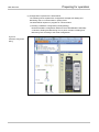
As an example, the following hardware configuration may appear:
Figure 8:
Hardware configuration
dialog
⇒ Click Disconnect to go into the offline mode if you want to change the
configuration of the MELSEC-WS modules.
3.4.2
Assignment of an IP address
⇒ If your project is online, click on the Disconnect button to go offline.
⇒ Click on the GETH Network Module [13] button (Network Modules button
when two network modules are used) above the main window and select the
desired Ethernet interface module.
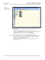
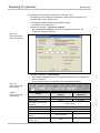
⇒ Click on Network module configuration on the left hand menu. The following
dialog appears:
22
Ethernet interface module
MELSEC-WS
Figure 9:
Network module
configuration dialog
On the left side of the dialog you will find the area for the Ethernet interface module
IP configuration.
Note
23
⇒ If desired, enter a Device name for the Ethernet interface module.
⇒ Enter a valid IP address, for the Ethernet interface module, and if required a valid
Subnet mask and a valid IP address for a Default gateway.
Or:
⇒ If your network uses a DHCP server, activate the DHCP checkbox.
If your project is online, you can use the Read button at the upper left corner of
the Ethernet interface module IP configuration area to retrieve the current IP
settings of the Ethernet interface module.
The out-of-the-box default IP address of the Ethernet interface module is
192.168.250.250.
Ethernet interface module
MELSEC-WS
You can assign an IP address from Network settings in the Connection settings
dialog.
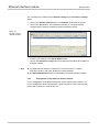
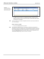
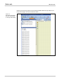
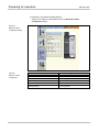
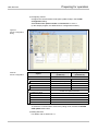
⇒ Click on the Network settings button. The Network scan dialog is opened.
⇒ Click on the Scan button. Your network is scanned for connected network
modules and the network modules found are displayed in the list.
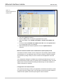
Figure 10:
List of the found
network modules
⇒ Click on the Ethernet interface module you want to edit.
⇒ Enter the new settings in the Edit IP Address area.
⇒ Click on the Set device config button to transfer the new settings to the Ethernet
interface module.
Note
If multiple Ethernet interface modules are connected to the PC, network
scanning may fail. In that case, disable the unused modules.
The Open Web Browser button is unavailable for Ethernet interface modules.
3.4.3
Configuration of the Ethernet interface module
For the configuration of the Ethernet interface module, please refer to Section 3.5.
For the configuration of the input data set 1 (data transfer from and to the network),
please refer to Section 4.4 and Section 4.5.
24
Ethernet interface module
MELSEC-WS
3.4.4
Transfer of a configuration
Once you have finished the configuration, you have to transfer the configuration to
your MELSEC-WS safety controller. In order to transfer a configuration, perform the
following steps:
⇒ Click Connect to go online. The Setting and Monitoring Tool connects to the
MELSEC-WS safety controller.
⇒ Click Transfer to transfer the configuration to the MELSEC-WS safety controller.
Note
Depending on your current user level, you will be prompted to log on as
Administrator to be able to transfer a configuration. For details please see the
Safety Controller Setting and Monitoring Tool Operating Manual.
⇒ Once the transfer has been completed, you will be asked whether you want to
run the CPU module. Depending on your choice, click Yes or No to leave the
dialog.
Note
25
You can also start and stop the application in the Hardware configuration view
using the Run application or Stop application buttons while the project is online.
More information can be found in the Safety Controller Setting and Monitoring Tool
Operating Manual.
Ethernet interface module
3.4.5
MELSEC-WS
Verification of a configuration
After the configuration has been transferred successfully, the MELSEC-WS safety
controller can be verified. To this purpose, the downloaded configuration data are
read back out from the safety controller and compared with the project data. If they
match, the data are displayed in a report. If the user confirms that they are correct,
the safety controller is considered to be verified.
Note
⇒ In the Hardware configuration view, click the icon Upload and Verify
configuration and compare the configuration. The Upload and Verify Result
window is opened.
⇒ Click Yes below at the question Set device to verified? if the displayed
configuration is the expected configuration. The safety controller is then
considered to be verified.
You have to be logged in as an Administrator in order to mark the device as
“verified”.
If the verification is completed successfully, a “Read in and compare” report that
provides the most important project information is created subsequently. You
can print out or store this report.
The status verified/not verified is indicated in the lower right-hand corner of the
Setting and Monitoring Tool and by the CV LED of the CPU module turning on.
Only if the device and the corresponding configuration have been marked as
verified, the Auto RUN Mode in the configuration of the CPU module is active. If
the configuration is not set to verified after power up, the safety controller stays
in Idle mode (CV LED on the CPU module flashing) and the safety controller
needs to be set to Run Mode using the Setting and Monitoring Tool.
If differences between the project data and the read-back configuration data are
detected, a corresponding message including information about possible actions
is displayed. Verification of the configuration is not possible then. Observe the
information in the error message for the further procedure. Terminate the dialog
box by clicking Close.
If you change a verified configuration, the status is reset to “not verified”.
Exception: If you make only non safety-related changes such as modifying the
Ethernet interface module name, the Ethernet interface module’s IP address or
the port number for a TCP/IP socket connection, the configuration status
remains “verified”.
More information can be found in the Safety Controller Setting and Monitoring Tool
Operating Manual.
3.4.6
Upload of a configuration
When in online mode, you can upload a configuration from the connected
MELSEC-WS safety controller:
⇒ Click on Upload. The current configuration of the safety controller will be
loaded into the Setting and Monitoring Tool and can be edited after going
offline.
26
Ethernet interface module
MELSEC-WS
3.5 Features of the Ethernet interface module
3.5.1
TCP/IP configuration interface
The Ethernet interface module offers offer a TCP/IP configuration interface which
allows the configuration of the MELSEC-WS safety controller over Ethernet TCP/IP.
This runs parallel to the Ethernet TCP/IP.
ATTENTION
Do not connect to the MELSEC-WS safety controller via the RS-232 and the
Ethernet interface at the same time!
The MELSEC-WS safety controller can only communicate with one instance of
the Setting and Monitoring Tool at one time. Connecting to the safety controller
using multiple instances of the Setting and Monitoring Tool, either on a single PC
or multiple PCs, may result in inconsistencies of the configuration and the
diagnostics as well as in operational errors. This applies to both RS-232 and
Ethernet connections equally.
In order to configure an interface for TCP/IP configuration for the first time, perform
the following steps:
Step 1: Assign an IP address
⇒ Connect a PC or notebook to the RS-232 interface of the CPU module.
⇒ Power on the MELSEC-WS safety controller.
⇒ Open the Setting and Monitoring Tool installed on the PC and load the hardware
configuration including the Ethernet interface module.
⇒ If your project is online, click on the Disconnect button to go offline.
⇒ Assign an IP address. For details, see Section 3.4.2.
⇒ Click on the Connect button to go online and transfer the new settings to the
MELSEC-WS safety controller.
Step 2: Add a TCP/IP profile to your project
⇒ Connect one of the two Ethernet ports of the Ethernet interface module with
your Ethernet network using a shielded Ethernet cable.
⇒ Connect a PC (or notebook) to the same Ethernet network. Ensure the IP
address settings of the PC match the network setup.
Note
You can also connect your PC directly to one of the two Ethernet ports of the
Ethernet interface module. In this case, you can either adapt the IP address
settings of your PC or the IP address settings of the Ethernet interface module to
match the other device’s IP setup.
⇒ Open the Setting and Monitoring Tool installed on the PC and load the
hardware configuration including the Ethernet interface module.
⇒ If your project is online, click on the Disconnect button to go offline.
⇒ Click on Com Settings. The following dialog appears:
27
Ethernet interface module
MELSEC-WS
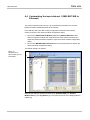
Figure 11:
Com Settings dialog
⇒ Click on Add TCP/IP Profile. The following dialog appears:
Figure 12:
Add TCP/IP Profile
dialog
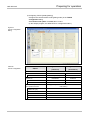
⇒ Click on Scan to search for Ethernet interface modules on your Ethernet
network. Ethernet interface modules located will be displayed as shown in the
dialog below. The IP address will be displayed as well as MAC address and
device name.
Note
If multiple Ethernet interface modules are connected to the PC, network scanning
may fail. In that case, disable the unused modules.
28
MELSEC-WS
Ethernet interface module
Figure 13:
Add TCP/IP Profile
dialog after scan has
been performed
⇒ Select the Ethernet interface module that you want to use as entry point.
⇒ Enter a name for the entry point to the Entry name edit field.
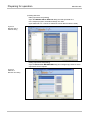
⇒ Click OK. The entry point has now been created and is shown in the
connection dialog:
Figure 14:
Connection settings
dialog with new TCP/IP
entry point
In order to use this entry point, it needs to be activated.
⇒ Click on the Activate Profile icon (white arrow in green circle) on the far right.
The entry point will then be activated and marked as such:
29
Ethernet interface module
MELSEC-WS
Figure 15:
Connection settings
dialog with new TCP/IP
entry point activated
⇒ Click OK. All communication to the MELSEC-WS safety controller will now
happen via TCP/IP. In order to use the entry point via the serial interface again,
you will have to re-activate it.
Note
The port number for the TCP/IP configuration interface is pre-set to port 9000 and
can not be changed.
Step 3: Connect via TCP/IP
⇒ Click on the Connect button to go online.
Note
While Setting and Monitoring Tool is connected via TCP/IP, do not transfer the
parameters in which the IP address of the connected Ethernet interface module has
been changed. Doing so will result in disconnection of communication. In that case,
click on the Disconnect button to go offline, make the correct configuration in the
Connection settings dialog, and then retry the connection.
30
Ethernet interface module
MELSEC-WS
3.5.2
Ethernet TCP/IP socket interface
Each Ethernet interface module supports a total number of four TCP/IP socket
interfaces. This allows up to four different applications to communicate with the
Ethernet interface module at the same time over Ethernet TCP/IP.
ATTENTION
Do not use the same output data set number for two different
programmable controller connections or TCP/IP sockets!
The output data set can be written to the Ethernet interface modules in parallel by
all communication interfaces or TCP/IP sockets, if they use the same output data
set number. In that case the last message overrides data received earlier.
The Ethernet interface module processes the data of a MELSEC-WS safety
controller and makes it available in different compilations, the data sets. These data
sets are available over the TCP/IP interface. For a detailed description of the data
sets please refer to Chapter 4.
In order to configure the Ethernet TCP/IP socket interface, perform the following
steps:
⇒ Open the Setting and Monitoring Tool and load the hardware configuration
including the Ethernet interface module.
⇒ Click on the GETH Network Module [13] button (Network Modules button
when two network modules are used) above the main window and select the
respective network module to open the network module configuration dialog.
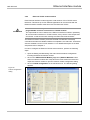
⇒ Click on TCP/IP configuration on the left hand menu. The following dialog
appears:
Figure 16:
TCP/IP configuration
dialog
31
Ethernet interface module
MELSEC-WS
Configuration of the TCP/IP interface - who establishes the connection
If the Ethernet interface module shall connect to the external application, perform
the following configuration steps:
⇒ Activate the Connect to radio button.
⇒ Set IP Address to the IP address of the computer the application is running on.
⇒ Enter the port number of the application for Port.
Note
The configuration is considered faulty if either the connect socket port and/or the
connect IP address is zero when in Connect mode.
If the external application shall connect to the Ethernet interface module, perform
the following configuration steps:
Note
⇒ Activate the Listen to radio button.
⇒ Enter the Port number for the application.
Suggested port numbers are 9100 to 9103 (default values).
Port 0 and port 9000 are reserved and can not be used (faulty configuration).
Port numbers 0 to 1023 are managed by the Internet Assigned Numbers
Authority (IANA) and can not be used. See
http://www.iana.org/assignments/port-numbers
Finally, determine how the data is transferred. Follow the steps outlined in the
following section.
Data transfer method - how the data is transferred
Whenever the TCP/IP socket connection has been established (either by an
application on a PC or by the Ethernet interface module itself), there are two
possible methods how the data sets can be transferred:
The application requests the data set(s) per command message (Application
requests (Polling) mode),
or
the Ethernet interface module auto-updates the data sets as per configuration
(Ethernet interface module writes to Address/Port (Auto update) mode).
For the auto update mode, there are two update modes how the Ethernet interface
module update the data:
Change of state (COS): when any data of the input data set change status.
Automatic update: data will be sent according to the configured update rate in
ms.
Note
If automatic update is enabled, a change of state will trigger an immediate update
of the data as well, regardless of the set update interval. (I.e. COS is always
active.)
For both methods the following structure of messages applies.
32
Ethernet interface module
MELSEC-WS
General telegram structure
The request/response message (e.g. telegram) is structured as shown below:
0
1
…
…
Command
Parameter(s)
…
…
…
…
…
…
…
…
…
…
n
Data
(content depends on type of command)
Each element in the request/response messages is transferred in Big Endian
format.
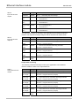
Table 3:
Telegram structure
Parameter
Command
Length
Description
WORD
0000H =
Undefined (no command)
Polling mode (input data set reading)
00F1H =
Input data set(s) request message
001FH =
Input data set(s) response message
Polling mode (output data set writing)
00F2H =
Write output data set settings
002FH =
Response to write output data set settings
Auto update mode
Parameter(s)
Length determined
00E1H =
Auto update control
001EH =
Auto update control response
002EH =
Auto update input data set(s) message
As defined in specific command
by command
Data
Length determined
As defined in specific command
by command
Error response to invalid messages
The Ethernet interface module will set the most significant bit of the command word
in the event that an invalid or improperly formatted message is received.
Table 4:
Error response
message
Parameter
Command
Length
WORD
Description
Bit 15 of received command will be set.
(i.e. command of 00F2H would become 80F2H.)
Following
Length
data
determined
Unchanged. Returned as it was received.
by command
Application requests (Polling) mode
In this mode the Ethernet interface module will only send any data upon request (e.g.
polling). Therefore the application shall send request telegrams as per definition
below and the Ethernet interface module will respond with telegrams structured as
per definition below.
Input data set reading
The request message is sent by an application to the Ethernet interface module. The
request message telegram shall be structured as shown below:
33
Ethernet interface module
Table 5:
Input data set read
request
Parameter
MELSEC-WS
Length
Value
Command
WORD
00F1H =
Request data
WORD
0 = Do not send data set 1.
set 1
Request data
1 = Send data set 1.
WORD
set 2
Request data
0 = Do not send data set 2.
1 = Send data set 2.
WORD
set 3
Request data
Data set(s) request message
0 = Do not send data set 3.
1 = Send data set 3.
WORD
set 4
0 = Do not send data set 4.
1 = Send data set 4.
The response message is returned to the application by the Ethernet interface
module. The response message telegram will be structured as shown below:
Table 6:
Input data set read
response
Parameter
Length
Command
WORD
Data set 1
WORD
length
Data set 2
WORD
Data set(s) response message
0 = Data set not returned in data set(s) data field
0 = Data set not returned in data set(s) data field
Non-zero = Length of data set
WORD
length
Data set 4
001FH =
Non-zero = Length of data set
length
Data set 3
Value
0 = Data set not returned in data set(s) data field
Non-zero = Length of data set
WORD
length
0 = Data set not returned in data set(s) data field
Non-zero = Length of data set
Data set(s)
Array of
data
bytes
Data set(s) information
Output data set writing
The following command message is sent by the application to the Ethernet
interface module to write to the output data sets:
Table 7:
Output data set write
request
Parameter
Length
Value
Command
WORD
00F2H =
Output data
WORD
0 = Output data set not included in data set(s) data field
set 1 length
Output data
Non-zero = Length of data set (10 bytes)
WORD
set 2 length
Output data
WORD
0 = Output data set not included in data set(s) data field
Non-zero = Length of data set (10 bytes)
WORD
set 4 length
Output data
0 = Output data set not included in data set(s) data field
Non-zero = Length of data set (10 bytes)
set 3 length
Output data
Set output data set(s) command message
0 = Output data set not included in data set(s) data field
Non-zero = Length of data set (10 bytes)
WORD
set 5 length
0 = Output data set not included in data set(s) data field
Non-zero = Length of data set (10 bytes)
Data set(s)
Array of
data
bytes
Data set(s) information
34
Ethernet interface module
MELSEC-WS
Note
Each output data set length of the Ethernet interface module is 10 bytes long.
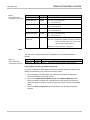
The response message is returned to the application by the Ethernet interface
module. The response message telegram is structured as shown below:
Table 8:
Output data set write
response
Parameter
Length
Value
Command
WORD
002FH =
Status
WORD
0 = Success. Output data sets written correctly.
Response to write output data set settings message
1 = Error - Can not write output data sets due to any of:
–
Stop state of the CPU module
–
Loss of backplane communication
–
Incorrect routing information
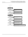
Configuration via Setting and Monitoring Tool
In order to configure the polling mode of the Ethernet interface module via the
Setting and Monitoring Tool, perform the following steps:
⇒ Open the Setting and Monitoring Tool and load the hardware configuration
including the Ethernet interface module.
⇒ Click on the GETH Network Module [13] button (Network Modules button
when two network modules are used) above the main window and select the
respective Ethernet interface module to open the network module configuration
dialog.
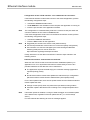
⇒ Click on TCP/IP configuration on the left hand menu. The following dialog
appears:
35
Ethernet interface module
MELSEC-WS
Figure 17:
TCP/IP configuration for
polling mode
⇒ Check the Listen to checkbox.
⇒ Enter the Port number on which the application will connect.
⇒ Select the update mode: Enable COS update or Enable auto update and
COS.
⇒ If you have selected Enable auto update and COS, select the Update rate in
ms. (Configurable range: 40 to 65535)
⇒ Select which data sets shall be updated: Check the Update Dataset n
checkbox.
Ethernet interface module writes to Address/Port (Auto update) mode
The Ethernet interface module can be configured to automatically update the data
set information (i.e. the application does not need to send any request messages
as it would do in polling mode) once the connection to the application has been
made.
The configuration settings are available via the Setting and Monitoring Tool or via
the TCP/IP interface itself. Using one interface does not disable the other: The auto
update mode could be enabled via Setting and Monitoring Tool and disabled via
TCP/IP command, for example.
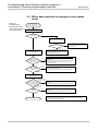
Configuration via TCP/IP interface
This command message is sent by an application to the Ethernet interface module
to configure the auto update mode. This message can be used to either disable or
enable the auto update mode directly through the TCP/IP interface.
36
Ethernet interface module
MELSEC-WS
Table 9:
Auto update mode
configuration command
Parameter
Length
Value
Command
WORD
00E1H =
Auto update control
Request data set 1
WORD
0 = Do not send data set 1.
1 = Send data set 1.
Request data set 2
WORD
0 = Do not send data set 2.
1 = Send data set 2.
Request data set 3
WORD
0 = Do not send data set 3.
Request data set 4
WORD
0 = Do not send data set 4.
1 = Send data set 3.
1 = Send data set 4.
Auto update mode
WORD
update rate
0 = Disable auto update messages.
Non-zero = Enable auto update message at specified
rate in ms. (If the value is 40 or less, data
sets are sent at 40ms interval.)
Minimum = 40 ms, Maximum = 65535 ms
Note
Auto update is disabled if all Request Input Data Set flags are set to zero.
The response message returned to the application by the Ethernet interface
module:
Table 10:
Auto update mode
configuration response
Parameter
Length
Command
WORD
Value
001EH =
Response to the auto update control message
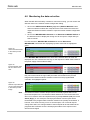
Configuration via Setting and Monitoring Tool
In order to configure the auto update mode of the Ethernet interface module via the
Setting and Monitoring Tool, perform the following steps:
⇒ Open the Setting and Monitoring Tool and load the hardware configuration
including the Ethernet interface module.
⇒ Click on the GETH Network Module [13] button (Network Modules button
when two network modules are used) above the main window and select the
respective Ethernet interface module to open the network module configuration
dialog.
⇒ Click on TCP/IP configuration on the left hand menu. The following dialog
appears:
37
Ethernet interface module
MELSEC-WS
Figure 18:
TCP/IP configuration for
auto update
⇒ Check the Connect to checkbox.
⇒ Enter the IP Address and the Port number the Ethernet interface module shall
write to.
⇒ Select the update mode: Enable COS update or Enable auto update and
COS.
⇒ If you have selected Enable auto update and COS, select the Update rate in
ms. (Configurable range: 40 to 65535)
⇒ Select which data sets shall be updated: Check the Update Dataset n
checkbox.
38
Ethernet interface module
MELSEC-WS
Normal operation
The following message is sent from the Ethernet interface module to the application
while operating in auto update mode.
Table 11:
Auto update mode
normal operation
message
Parameter
Length
Value
Command
WORD
002EH = Auto update data set(s) message
Data set 1 length
WORD
0 = Data set not returned in data set(s) data field
Non-zero = Length of data set
Data set 2 length
WORD
0 = Data set not returned in data set(s) data field
Data set 3 length
WORD
0 = Data set not returned in data set(s) data field
Data set 4 length
WORD
0 = Data set not returned in data set(s) data field
Data set(s) data
Array of bytes
Data set(s) information. Details see Section 4.1
(length dependent
and Section 4.3.
Non-zero = Length of data set
Non-zero = Length of data set
Non-zero = Length of data set
on set definition)
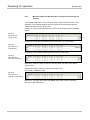
3.5.3
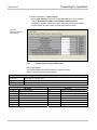
TCP/IP process image example
The following example shows a possible process image sent by an Ethernet
interface module via TCP/IP in auto update mode:
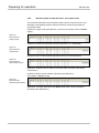
Table 12:
TCP/IP process image
example
Byte values
(hex)
00 2E
Part of message
Command
00 32
Meaning
Auto update data sets (see Table 11)
Length of data set 1: 50 bytes
00 20
Command
00 3C
parameters
Length of data set 2: 32 bytes
Length of data set 3: 60 bytes
00 3C
Length of data set 4: 60 bytes
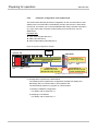
03 FF 03 03
Logic results 1-4
C0
Input values module 1:
C0 = 11000000 = Inputs I8 and I7 Active
03
Input values module 2:
03 = 00000011 = Inputs I2 and I1 Active
3F 05
05 05 00 00
00 00 00 00
00 00 00 00
00 00 00 00
00 00 00 00
Data set 1
Input values module 3-12
(default byte
assignments, see
Table 14)
Output values module 1-12
00 00 00 00
00 00 00 00
00 00 00 00
00 00 00 00
00 00 00 00
00 00
39
Not assigned
Ethernet interface module
Byte values
(hex)
MELSEC-WS
Part of message
Meaning
52 A1 10 4C
Overall CRC (same as system CRC)
52 A1 10 4C
System CRC
00 00 00 00
00 00 00 00
Data set 2
00 00 00 00
(see Table 14)
00 00 00 00
Reserved
00 00 00 00
00 00 00 00
FF FF FF FF
Status module 0 (WS0-CPU0/WS0-CPU1): OK
FF FF FF FF
Status module 1 (e.g. WS0-XTDI): OK
FD FB FF FF
Status module 2 (e.g. WS0-XTIO):
Byte 0: FF = 11111111: No errors
Byte 1: FF = 11111111: No errors
Data set 3
(see Table 14 and
Table 15)
Byte 2: FB = 11111011: Input 3 external test
signal failure
Byte 3: FD = 11111101: Output 1 stuck-at-low
error
Data set 3 data is
FF FF FF FF
transferred in Big
FF FF FF FF
Endian format, i.e. in
FF FF FF FF
32 bit double word
FF FF FF FF
format with the most
FF FF FF FF
significant byte (byte 3)
FF FF FF FF
placed in the leftmost
FF FF FF FF
position.
FF FF FF FF
Status modules 3-6: OK
Status modules 7-12 (no modules present)
FF FF FF FF
FF FF FF FF
FF FF FF FF
Status module 13 (e.g. WS0-GETH): OK
FF FF FF FF
Status module 14 (no module present)
40
Ethernet interface module
MELSEC-WS
Byte values
(hex)
Part of message
Meaning
00 00 00 00
00 00 00 00
00 00 00 00
00 00 00 00
00 00 00 00
00 00 00 00
00 00 00 00
00 00 00 00
00 00 00 00
00 00 00 00
00 00 00 00
00 00 00 00
00 00 00 00
00 00 00 00
00 00 00 00
41
Data set 4
Reserved
Data sets
MELSEC-WS
4. Data sets
The Ethernet interface module allows the MELSEC-WS safety controller to send
and receive non-safety related data to and from the external fieldbus system for
control and diagnostics purposes.
Note
ATTENTION
In this manual, the data exchanged between the MELSEC-WS safety controller and
the respective network will be considered always from the network master
(programmable controller) point of view. Therefore data sent from the MELSEC-WS
safety controller into the network will be referred to as input data while data
received from the network will be referred to as output data.
Do not operate an Ethernet interface module on a safety fieldbus!
The Ethernet interface module is not suitable for operation on a safety fieldbus. It
does not support any safety mechanism, which would be mandatory to
communicate within a safety network.
Configuration of the Ethernet interface module is performed using the Setting and
Monitoring Tool on a PC or laptop connected to the CPU module over RS-232
interface or connected to the Ethernet interface module over Ethernet TCP/IP.
Configuration data can be exported, imported, and saved.
The safety relevant logic of the MELSEC-WS safety controller operates
independently from the Ethernet interface module. If however the MELSEC-WS
safety controller has been configured to integrate non-safe information from the
fieldbus into the logic editor, a decoupling of the Ethernet interface module can
result in availablity problems.
An Ethernet interface module can only be operated on a MELSEC-WS safety
controller. It does not have a dedicated voltage supply. It is possible to use two
network modules per system.
The Ethernet interface module is fitted in a 22.5 mm wide housing for 35 mm rails
in accordance with EN 60715.
42
Data sets
MELSEC-WS
4.1 Data transmitted into the network (network input
data sets)
Available data
The Ethernet interface module can provide the following data:
Operational data
– Logic results from the CPU module (see Section 4.1.1.)
– Input values (Active/Inactive) for all safety I/O modules in the system and
EFI devices connected (see Section 4.1.2.)
– Output values (Active/Inactive) for all safety I/O modules and EFI devices
connected (see Section 4.1.2.)
– Output data from another network, i.e. data received by a second network
module in the safety controller (see Section 4.1.3.)
Diagnostics
– Checksums (CRCs) (see Section 4.1.4.)
– Error and status information for all modules except the safety relay output
module (see Section 4.1.5.)
Data sets
Input data sets to be sent from the Ethernet interface module to the network consist
of logic results, I/O state data, diagnostics data (e.g. module status, CRC), and
other data. These data are organized into four input data sets.
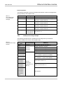
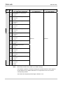
Table 13:
Description of input
data sets 1 to 4
Input data set
1
Description
Logic result
Size
Customization
50 bytes
Available
Module and EFI input
and output values
Data set of the second
network module
2
CRC
32 bytes
N/A
3
Error and status information
60 bytes
N/A
60 bytes
N/A
of the module
4
Reserved
For details of data to be sent to the network, see Table 14 and Table 15.
You can customize the contents of input data set 1 in units of 1 byte. In the delivery
status, the input data set 1 is pre-configured (default settings). (See Section 4.3 and
Section 4.4.)
43
Data sets
MELSEC-WS
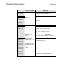
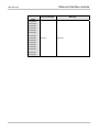
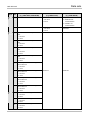
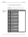
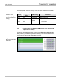
Table 14 shows the overview of data sets available for the Ethernet interface
module.
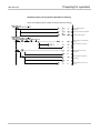
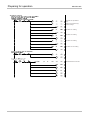
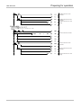
Table 14:
Overview input data
sets 1 to 3
Data set 1 (default)
Data set 2
Overall CRC
Module status module 0.
Module 0 is always the CPU.
For detailed information about
the module status see Table 15.
System CRC
(SCID)
Module status module 1
Reserved
Module status module 2
Byte 0
Logic result 0
Byte 1
Byte 2
Logic result 1
Logic result 2
Byte 3
Byte 4
Logic result 3
Input values module 1
Byte 5
Byte 6
Input values module 2
Input values module 3
Byte 7
Byte 8
Input values module 4
Input values module 5
Byte 9
Byte 10
Input values module 6
Input values module 7
Byte 11
Byte 12
Input values module 8
Input values module 9
Byte 13
Byte 14
Input values module 10
Input values module 11
Byte 15
Byte 16
Input values module 12
Output values module 1
Byte 17
Byte 18
Output values module 2
Output values module 3
Byte 19
Byte 20
Output values module 4
Output values module 5
Byte 21
Byte 22
Output values module 6
Output values module 7
Byte 23
Byte 24
Output values module 8
Output values module 9
Byte 25
Byte 26
Output values module 10
Output values module 11
Byte 27
Byte 28
Output values module 12
Not assigned
Byte 29
Byte 30
Not assigned
Not assigned
Byte 31
Byte …
Not assigned
Not assigned
…
Byte 49
Byte …
Not assigned
No data
…
…
Module status module 3
Module status module 4
Module status module 5
Module status module 6
Module status module 7
Byte 56
Byte 57
Module status module 14.
Module 13 and 14 are always
the network modules.
Byte 58
Byte 59
Length
Note
Data set 3
50 bytes
32 bytes
60 bytes
If there are dual channel input or output elements configured at the safety I/O
module, then only the lowest bit represents the element’s input or output status
(on/off). It is represented by the element’s tag name. The highest bit is not
supported.
44
Data sets
MELSEC-WS
4.1.1
Logic results
Logic results generated by the logic editor of the CPU module can be made
available to the network. Up to 20 bytes are available where each bit represents
one logic result from the logic editor.
Data set 1 containing the logic results can be customized. For detailed information
see Section 4.4.
4.1.2
Module and EFI input and output values
The Ethernet interface module can transmit all input and output states of all
MELSEC-WS modules and EFI devices connected to the MELSEC-WS safety
controller into the network. Data set 1 containing the input and output values and
the EFI information can be customized. For detailed information see Section 4.4.
Module input and output states
The input and output states of the modules are transmitted using one byte for each
module’s inputs and one byte for each module’s outputs where each bit represents
the state of one input or output (on/off).
EFI system information
The WS0-CPU1 module has 2 EFI interfaces. An EFI interface is a safe
communication interface between SICK devices. It allows to
read out information from the safety devices (e.g. SICK C4000, S3000)
transfer commands to the safety devices
The Ethernet interface module allows these EFI devices connected to the
WS0-CPU1 to transmit their data into the network.
Note
It is only possible to select the EFI data in byte arrays. 4 byte arrays for each
connected EFI device are available. Some of the data contents are reserved and
can not be used at the programmable controller.
Further information about the properties, functions and benefits of the EFI
interfaces can be found in the Safety Controller User’s Manual.
4.1.3
Routing of data from a second network
If your MELSEC-WS safety controller contains two network modules, it is possible
to route information received by the first network module from one network (e.g.
from a programmable controller) into a second network via the second network
module (e.g. to an HMI) and vice versa.
45
Data sets
MELSEC-WS
4.1.4
Configuration checksums (CRCs)
Data set 2 contains the following configuration CRCs for the MELSEC-WS safety
controller:
Overall CRC (same as system CRC)
System CRC (SCID)
Each checksum is four bytes long. The overall CRC is the checksum displayed in
the Setting and Monitoring Tool report. Data set 2 can not be customized.
4.1.5
Error and status information of the modules
Data set 3 contains the module status information transferred to the network.
Four bytes are used for each module (e.g. WS0-XTIO). These four bytes are being
transferred in Big Endian format, i.e. in 16 bit word format with the first byte placed
in the least significant, or rightmost byte of the integer and the second byte placed
in the most significant, or leftmost byte of the integer:
Data set 3 can not be customised.
Meaning of the module status bits
Table 15: Meaning of the module status bits
Byte
0
Bit
Safety I/O modules
(e.g. WS0-XTIO, WS0-XTDI)
CPU modules
(e.g. WS0-CPUx)
Network modules
(e.g. WS0-GETH)
0
Module operating state
1 = Executing
0 = Any other state
Module operating state
1 = Executing
0 = Any other state
Module operating state
1 = Executing
0 = Any other state
1
Internal error: Internal tests failed or
watchdog test failed or bad process
data or self test failure
1 = No error
0 = Error
Module operating state is
Critical Fault.
1 = No error
0 = Critical Fault
Internal error: Internal tests
failed, bad process data
1 = No error
0 = Error
2
External error: Input test or dual
channel evaluation failure, or bad
output power supply range, or output(s)
stuck-at-high or stuck-at-low.
1 = No error
0 = Error
Power supply out of range or
EFI communication failure
1 = No error
0 = Error
External error: network
connection inactive/failure
1= No error
0 = Error/inactive
3
Reserved
Reserved
Reserved
4
Configuration status changed to invalid. Configuration status changed
1 = Configuration valid
to invalid.
0 = Conf. invalid or unknown
1 = Configuration valid
0 = Conf. invalid or unknown
Output power supply out of range.
Output power supply out of
1 = Power supply o.k.
range.
0 = Power supply out of range
1 = Power supply o.k.
0 = Power supply out of range
5
Configuration status changed
to invalid.
1 = Configuration valid
0 = Conf. invalid or unknown
Input status
1 = Valid network
communication
0 = Invalid or no
communication
46
Data sets
MELSEC-WS
Safety I/O modules
(e.g. WS0-XTIO, WS0-XTDI)
CPU modules
(e.g. WS0-CPUx)
Network modules
(e.g. WS0-GETH)
Byte
Bit
0
6
Reserved
EFI 1 communication failure
1 = No error
0 = Error
7
Reserved
EFI 2 communication failure
1 = No error
0 = Error
Reserved
Reserved
Reserved
1
0
1
2
3
4
5
6
7
2
47
Input 1-2 dual channel input evaluation
error
1 = No error
0 = Error
Input 3-4 dual channel input evaluation
error
1 = No error
0 = Error
Input 5-6 dual channel input evaluation
error
1 = No error
0 = Error
Input 7-8 dual channel input evaluation
error
1 = No error
0 = Error
Status output 1 fast shut off logic
control time out.
1 = No error
0 = error
Status output 2 fast shut off logic
control time out.
1 = No error
0 = error
Status output 3 fast shut off logic
control time out.
1 = No error
0 = error
Status output 4 fast shut off logic
control time out.
1 = No error
0 = error
0
Input 1 external test signal failure.
1 = No error
0 = Error
1
Input 2 external test signal failure.
1 = No error
0 = Error
Input 3 external test signal failure.
1 = No error
0 = Error
2
Output status
1 = Valid network
communication
0 = Invalid or no
communication
Data sets
MELSEC-WS
Safety I/O modules
CPU modules
Network modules
(e.g. WS0-XTIO, WS0-XTDI)
(e.g. WS0-CPUx)
(e.g. WS0-GETH)
Byte
Bit
2
3
Input 4 external test signal failure.
1 = No error
0 = Error
4
Input 5 external test signal failure.
1 = No error
0 = Error
5
Input 6 external test signal failure.
1 = No error
0 = Error
6
Input 7 external test signal failure.
1 = No error
0 = Error
Input 8 external test signal failure.
1 = No error
0 = Error
Output 1 stuck-at-high error.
1 = No error
0 = Error
Output 1 stuck-at-low error.
1 = No error
0 = Error
7
3
0
1
2
Output 2 stuck-at-high error.
1 = No error
0 = Error
3
Output 2 stuck-at-low error.
1 = No error
0 = Error
4
Output 3 stuck-at-high error.
1 = No error
0 = Error
Output 3 stuck-at-low error.
1 = No error
0 = Error
Output 4 stuck-at-high error.
1 = No error
0 = Error
Output 4 stuck-at-low error.
1 = No error
0 = Error
0 = Error
5
6
7
Note
Reserved
Reserved
Reserved (for future use) = static 1 (no status change)
If no module is present, all values including the reserved values are set to logical 1.
In input data set 3, the status value will be “0” only when an error occurs in the
corresponding module.
You will find an example process image in Section 3.5.3.
48
Data sets
MELSEC-WS
4.2 Data received from the network (network output
data sets)
The data received from the network are organized in output data sets (max. 50
bytes). These data have been subdivided in five data blocks holding 10 bytes each
for the Ethernet interface module.
Table 16:
Output data blocks 1 to
5 for the Ethernet
interface module
Output
Output
Output
Output
Output
data block
data block
data block
data block
data block
1 size
2 size
3 size
4 size
5 size
WS0-GETH 10 bytes
10 bytes
10 bytes
10 bytes
10 bytes
The contents of the output data blocks can be used within the Setting and
Monitoring Tool logic editor and can also be made available to another network via
a second network module in the MELSEC-WS safety controller.
Note
In order to make the data from the network available in the logic editor or as
input to another network, you will have to define a tag name for each bit that
shall be used.
Bits without a specific tag name will not be available in the logic editor nor for
routing via another network module. For detailed information on how to define
tag names for the data received please see Section 4.5.
The status of the communication to and from the network can be monitored in
the logic editor using the module input status bit for data from the network and
the module output status bit for data to the network. When the Ethernet interface
module detects an invalid communication, the contents of the data sets will be
set to zero (logical 0) and the corresponding module status bit will also be set to
zero (logical 0).
In case the communication is dropped, the data of the output data sets will be
set to zero (logical 0) and the module input status bit will also be set to zero
(logical 0).
These modules may only be used by qualified safety personnel and only on the
machine where they have been installed and initialized by qualified safety
personnel in accordance with the manual.
ATTENTION
49
Do not use the same output data set number for two different interface
connections or TCP/IP sockets!
The output data set can be written to the Ethernet interface modules in parallel by
all communication interfaces or TCP/IP sockets, if they use the same output data
set number. In that case the last message overrides data received earlier.
Data sets
MELSEC-WS
4.3 Default settings for the input data set 1
In the delivery status, the input data set 1 of the Ethernet interface module is
pre-configured.
The following table gives an overview which bytes are assigned to the default
configuration and how the data are modularised.
Table 17:
Default configuration for
the input data set 1
transmitted into the
network
Byte
Default assignment
0
Logic result 0
1
Logic result 1
2
Logic result 2
3
Logic result 3
4
Module 1 input
5
Module 2 input
6
Module 3 input
7
Module 4 input
8
Module 5 input
9
Module 6 input
10
Module 7 input
11
Module 8 input
12
Module 9 input
13
Module 10 input
14
Module 11 input
15
Module 12 input
16
Module 1 output
17
Module 2 output
18
Module 3 output
19
Module 4 output
20
Module 5 output
21
Module 6 output
22
Module 7 output
23
Module 8 output
24
Module 9 output
25
Module 10 output
26
Module 11 output
27
Module 12 output
28 to 35
Not assigned
36 to 47
Not assigned
48 to 49
Not assigned
Input data set
#1
(50 bytes)
The default byte assignment can be freely customised as will be described in the
following section.
50
Data sets
MELSEC-WS
4.4 Customizing the input data set 1 (MELSEC-WS to
Ethernet)
This section outlines briefly how you can customize the input data set 1 that the
Ethernet interface module transmits to the network.
In the delivery status, the data routing configuration of the Ethernet interface
module is shown in the network module configuration dialog.
⇒ Click on the GETH Network Module [13] button (Network Modules button
when two network modules are used) above the main window and select the
respective Ethernet interface module to open the network module configuration
dialog.
⇒ Click on the MELSEC-WS to Ethernet tab on the left hand menu to display the
network module configuration dialog.
The default setting is as follows:
Figure 19:
MELSEC-WS to
Ethernet dialog of the
WS0-GETH
4)
1)
2)
1)
3)
Basically this dialog is divided into three areas: Available data (1)), Network
Module Data (2)) and Tag Names (3)). The upper left corner of the dialog holds the
toolbar (4)).
51
Data sets
MELSEC-WS
4.4.1
The toolbar
Figure 20:
Toolbar for the routing
configuration
The toolbar contains buttons for the following actions (from left to right):
The Load user configuration and Save user configuration buttons allow you
to load and/or save a configuration in XML format. If you load a configuration, all
previously made changes that have not been saved will be lost. You can not
undo this action.
With the Import and Export buttons you can import and export a configuration
including the tag names used as a CSV (comma separated values) file. This
allows you to import and use the assigned tag names in a programmable
controller program. To edit the CSV file, use a text editor.
Note
When importing the exported network module data after editing the data in a text
editor such as Notepad, select CSV Files - Shift-JIS encoded for Files of type in the
Open dialog box if the data is saved in ANSI format. If not, characters in the data may
get garbled.
The Import button is only available for the Ethernet to MELSEC-WS routing
configuration.
Reset to default restores the default routing configuration. You will be prompted
for confirmation. If you click Yes, all previously made changes that have not
been saved will be lost. You can not undo this action.
Clear all clears the configuration, i.e. deletes all assigned bytes in the Network
Module Data area. You will be prompted for confirmation.
Delete Routing deletes the selected byte from the Network Module Data area.
The Undo and Redo buttons allow you to undo or redo changes you made to
your configuration.
52
Data sets
MELSEC-WS
4.4.2
Available data area
This area offers all sources from which data may be routed into the network. It is
divided in two views holding the available Input types and Output data. You can
switch between these views using the file cards at the bottom.
The Input types view contains the input values for the connected MELSEC-WS
modules and EFI devices. If your MELSEC-WS safety controller contains a
second network module, the input data of this network module (i.e. data received
from the network the second network module is connected to) will be available
here as well.
The Output view offers the output values for the connected MELSEC-WS
modules and EFI devices as well as the Logic results from the logic editor.
All sources supported by the current configuration are displayed in black:
connected MELSEC-WS modules
connected EFI devices
*1
configured logic results
input data available from another network module in the system
*1 In the default configuration, only the first logic result byte (Logic Result 0) is active and available. You
can activate more logic result output bits in the logic editor.
Sources currently not configured will be displayed in grey. Activating the Show only
available data checkbox in the upper left corner hides the unused sources from the
view.
Sources that offer “live” data are marked with a little icon next to the text.
How to add a data byte to the routing table:
⇒ Drag and drop an element (i.e. byte) from the Available data area to a free slot
in the Network Module Data area. If the desired position is not free, you will
have to clear it first by deleting or moving the byte currently assigned to it.
Note
53
It is possible to use the same byte several times in the routing table.
Data sets
MELSEC-WS
4.4.3
Network Module Data area
This area contains the routing table. It shows the current content of the Ethernet
interface module’s input data modules. Bytes and bits highlighted blue will hold
“live” data from the system since the hardware configuration does support the
source. Bytes highlighted grey actually do not have data associated with them
since the hardware configuration does not support the sources.
How to delete a data byte from the routing table:
⇒ Drag and drop the byte you want to delete to the trashcan icon in the bottom
left corner of the Network Module Data area.
Or:
⇒ Select the byte you want to delete by clicking it with the left mouse button. Then,
click on the Delete Routing button in the toolbar.
Or:
⇒ Call up the context menu by clicking the respective byte with the right mouse
button. In the context menu, select the Delete Routing command.
How to move a data byte to another place in the routing table:
⇒ Drag and drop the byte you want to move to the desired position. If the desired
position is not free, you will have to clear it first by deleting or moving the byte
currently assigned to it.
4.4.4
Tag names area
This area shows the tag names associated with each bit of the byte currently
selected in the Available data or the Network Module Data area. You can enter
these tag names in the logic editor and in the hardware configuration dialog (e.g.
for safety I/O modules).
In the Tag Names area of the MELSEC-WS to Ethernet configuration dialog, it is
not possible to edit the tag names.
54
Data sets
MELSEC-WS
4.5 Tag names for incoming data (Ethernet to
MELSEC-WS)
In order to enable incoming data bits:
⇒ Click on Ethernet to MELSEC-WS on the left hand menu. The following dialog
appears:
Figure 21:
Ethernet to
MELSEC-WS dialog of
the WS0-GETH
1)
2)
Basically this dialog is divided into two areas: Network Module Data (1)) and Tag
Names (2)):
The Network Module Data area shows the current configuration of the output
modules.
The Tag Names area shows the tag names associated to the byte selected in the
Network Module Data area.
⇒ Select a byte in the Network Module Data area.
⇒ For each bit of the selected byte that you wish to use, enter a tag name in the
Tag Names area.
55
Data sets
MELSEC-WS
Each bit you enter a tag name for here will be available within the logic editor or for
the process image of a second network module:
Figure 22:
Tag names of incoming
bits of the WS0-GETH
in the logic editor dialog
56
Data sets
MELSEC-WS
4.5.1
Saving and loading a configuration
Using the buttons Load user configuration and Save user configuration you can
save and load your configuration in XML format. If you load a configuration, all
previously made changes that have not been saved will be lost. You can not undo
this action.
4.5.2
Importing and exporting a configuration
With the Import and Export buttons you can import and export a configuration
including the tag names used as a CSV (comma separated values) file. This allows
you to import and use tag names you have assigned in the MELSEC-WS safety
controller project in another programmable controller program and vice versa. To
edit the CSV file, use a text editor.
If you import a configuration, all previously made changes that have not been
saved will be lost. You can not undo this action.
Note
57
The Import button is only available for the Ethernet to MELSEC-WS routing
configuration.
Data sets
MELSEC-WS
4.6 Monitoring the data set online
When the MELSEC-WS safety controller is online and running, you can monitor the
data set online in the network module configuration dialog.
⇒ Click on the GETH Network Module [13] button (Network Modules button
when two network modules are used) above the main window and select the
respective Ethernet interface module to open the network module configuration
dialog.
⇒ Click on the MELSEC-WS to Ethernet or the Ethernet to MELSEC-WS tab on
the left hand menu to display the routing view for the input or output data you
want to monitor.
For both directions, MELSEC-WS to Ethernet as well as Ethernet to
MELSEC-WS, inactive bits are displayed grey while active bits are highlighted
green:
Figure 23:
Active and inactive bits
in the online process
image
In the MELSEC-WS to Ethernet view, bits that are inactive due to an error are
displayed red. This could be the case e.g. for the outputs of a WS0-XTIO module if
the power supply of this module is faulty:
Figure 24:
Inactive Network input
bits as a result of an
error
In the Ethernet to MELSEC-WS view, bits that have no tag name assigned (so that
they can not be used in the logic editor) but which are included in the process
image that the Ethernet interface module receives from the programmable
controller, are highlighted yellow:
Figure 25:
Network output bits with
no tag names assigned
in the online process
image
Note
The Ethernet interface module always reflects the actual physical status of the
inputs and outputs on the connected modules and devices. This means that even
when Force mode is active and inputs that are physically Inactive (Low) are forced
Active (High) (or vice versa) the actual physical status of these inputs will be
transmitted to the programmable controller instead of the (virtual) forced status. If,
however, as a result of forcing of one or several inputs, one or several outputs
change their status, the changed status of these outputs will be transmitted to the
programmable controller since the actual physical status of the outputs on the
devices has changed.
58
Troubleshooting
MELSEC-WS
5. Troubleshooting
For information how to perform diagnostics on the MELSEC-WS safety controller
please refer to the Safety Controller Setting and Monitoring Tool Operating Manual.
Note
Check the LEDs of the module during troubleshooting.
Table 18: Troubleshooting for the WS0-GETH
Error
Cause
Possible remedy
The Setting and Monitoring Tool WS0-GETH has no power supply.
Establish the power supply.
does not connect to the
WS0-GETH is not in the same
Check the Ethernet wiring and network
Ethernet interface module.
physical network as the PC.
settings on the PC and correct if necessary.
The PC is configured to another
Set the subnet mask on the PC to 255.255.0.0
subnet mask in the TCP/IP settings.
(factory setting of the WS0-GETH).
WS0-GETH has already been
Check the communication settings in the
configured once and has a fixed set
Setting and Monitoring Tool.
IP address or an IP address
assigned by a DHCP server that is
not recognised.
WS0-GETH does not supply
WS0-GETH is configured for data
Minimum one Ethernet connection needs to be
any data.
transfer to programmable controller,
established. Set up Ethernet connection on
LED PWR z Green
but Ethernet communication is not
programmable controller side, check Ethernet
yet established or faulty.
cabling, check Ethernet connection settings on
Duplicate IP address detected.
programmable controller and in the Setting
Another device on the network has
and Monitoring Tool. If no Ethernet
the same IP address.
communication is required, disable the
LED LINK/ACT z/
LED MS
Green
Red/Green
Ethernet connections/PLC interfaces on the
WS0-GETH.
Adjust IP address and power cycle device.
WS0-GETH does not supply
Configuration required.
Configure the WS0-GETH and download the
any data.
Configuration download is not
configuration to the safety controller.
completed.
Wait until the configuration download has been
LED PWR z Green
LED LINK/ACT z/
LED MS
Green
completed.
Red (1 Hz)
WS0-GETH does not supply
No data set is activated.
any data.
No Ethernet communication interface communication in auto update mode.
LED PWR z Green
is enabled.
LED LINK/ACT z/
Activate at least one data set for
Green
LED MS z Green
WS0-GETH does not supply
LED PWR z Green
LED LINK/ACT z/
59
CPU/application is stopped. Start CPU
(change into Run mode).
any data.
LED MS
WS0-GETH is in Idle mode.
Green
Green (1Hz)
Troubleshooting
MELSEC-WS
Error
Cause
Possible remedy
WS0-GETH functioned correctly WS0-GETH is operated in slave
Either assign a fixed IP address to the
after configuration, but suddenly mode, the IP address is assigned
WS0-GETH, or reserve a fixed IP address for
no longer supplies data.
from a DHCP server. After the
the WS0-GETH in the DHCP server (manual
LED PWR z Green
WS0-GETH or the DHCP server has assignment by means of the MAC address of
Green
LED LINK/ACT z/
LED MS
Red/Green
been restarted, a different IP address the WS0-GETH).
that is unknown to the programmable
controller has been assigned to the
WS0-GETH.
WS0-GETH/safety controller is
WS0-GETH is not plugged properly
Plug the WS0-GETH in correctly.
in Critical fault mode.
into the other MELSEC-WS module.
Clean the connecting socket/plug.
LED PWR z Green
Module connection plug is soiled or
Repower the safety controller.
damaged.
Check the error MELSEC-WS module and
Other MELSEC-WS module has
remove the error cause.
internal critical error.
Check the Ethernet line status. If a load is
Ethernet communication with the
excessively placed to the line, reduce the load
WS0-GETH is under excessive load.
using a device such as a router.
LED LINK/ACT
Green
LED MS z Red
WS0-GETH is in Critical fault
WS0-GETH internal device error
Switch off the power supply of the safety
mode.
controller and switch it on again.
LED PWR z Green
Check if the WS0-GETH is mounted in correct
LED LINK/ACT z/
LED MS
Green
Red (2 Hz)
position.
Check the diagnostics messages with the
Setting and Monitoring Tool.
If the error remains, replace the Ethernet
interface module.
60
Technical specifications
MELSEC-WS
6. Technical specifications
6.1 Technical specifications of Ethernet interface
module
Table 19:
Technical specifications
of Ethernet interface
module
Interface
Fieldbus
Integrated switch
Ethernet TCP/IP
3-port layer-2 managed switch with Auto-MDI-X for
automatic detection of crossed Ethernet cable
Connection technique
Transfer rate
RJ45 socket
10 Mbps (10Base-T) or 100 Mbps (100Base-TX),
autosensing
Update rate
(heartbeat rate)
Change of state (COS)
update rate
Addressing factory
setting
Configurable from 40 to 65535 ms
10 ms
IP address: 192.168.250.250
Subnet mask: 255.255.0.0
Default gateway: 0.0.0.0
MAC address
Printed on type label, example: 00:06:77:02:00:A7
6.2 Technical specifications, supply circuit
Table 20:
Technical specifications,
supply circuit
Item
Specifications
Supply voltage
24 V DC (16.8 to 30 V DC)
Power consumption
Max. 2.4 W
6.3 General technical specifications
Table 21:
General technical
specifications
Terminals
Fieldbus
Ethernet (TCP/IP)
FLEXBUS+
10-pin connector for internal safety bus (plug)
Climatic conditions
61
Ambient operating temperature TA
-25 °C to +55 °C
Storage temperature
-25 °C to +70 °C
Relative humidity
10 % to 95 %, non-condensing
Climatic conditions
In accordance with EN61131-2
Technical specifications
MELSEC-WS
Mechanical strength
Vibration resistance, shock resistance
Tested in accordance with IEC61161-2.
Electrical safety (see WS0-CPUx)
Protection class
III
Electromagnetic compatibility
EN 61000-6-2/EN 55011 Class A
Mechanical and assembly
Housing material
Polycarbonate
Housing type
Device for control cabinet installation
Housing enclosure rating/terminals
IP 40/IP 20
Housing color
Light grey
Weight
125 g
Data interface
FLEXBUS+ backplane bus
Ethernet interface
One connector on the top and one
connector on the bottom
Mounting rail
Mounting rail according to EN 60715
62
Technical specifications
MELSEC-WS
6.4 Dimensional drawings
Figure 26:
Dimensional drawings
of WS0-GETH (mm)
Unit : mm
6.5 Module information
Table 22:
Module information
Type
Module name
WS0-GETH00200
MELSEC-WS safety controller Ethernet interface
module
63
Abbreviation
WS0-GETH
Connecting to a Q series programmable controller
MELSEC-WS
7. Connecting to a Q series programmable controller
This chapter describes the exchange of non-safety related data (input/output data)
with a Q series programmable controller via TCP/IP.
In this or later chapters, to clarify the MELSEC-WS safety controller system and
MELSEC programmable controller system, each Ethernet interface module is
referred to as follows:
Ethernet interface module → WS0-GETH
MELSEC QJ71E71-100 Ethernet interface module → QJ71E71-100
7.1 Features achieved by the connection
Obtaining information in a MELSEC-WS safety controller from a Q series
programmable controller over Ethernet
The QJ71E71-100 or Built-in Ethernet port QCPU can read the MESLEC-WS
safety controller information (e.g. operation results of the CPU module, safety
input/output data).
This feature allows you to obtain the MELSEC-WS safety controller information
from the Q series programmable controller.
Two communicaton modes are available: polling mode and auto update mode.
Figure 27: Obtaining information in a MELSEC-WS safety controller from a Q series
programmable controller
Hub
WS0-GETH
<Setting and Monitoring Tool>
QJ71E71-100
MELSEC
Q61P
Q25HCPU
POWER
MODE
RUN
ERR.
USER
BAT .
BOOT
Operation results of
CPU module
QJ 71E71-100
RUN
INIT.
OPEN
SD
ERR.
C O M.
ERR .
1 0 0M
RD
MELSEC-WS safety controller information
All information is
batch-sent as
“data sets”.
Input/output signal state
Module status
USB
Operation
result
RS - 232
MITSUBISHI
<MELSEC-Q series programmable controller>
<MELSEC-WS safety controller>
Safety controller information can
be read from the QJ71E71-100 or
Built-in Ethernet port QCPU .
Output
Input
64
Connecting to a Q series programmable controller
MELSEC-WS
Notifying information from a Q series programmable controller to a
MELSEC-WS safety controller over Ethernet
The QJ71E71-100 or Built-in Ethernet port QCPU can send data to the
MELSEC-WS safety controller.
The send data can be used as input data for a function block in the logic editor of
Setting and Monitoring Tool. This feature allows you to notify the MELSEC-WS
safety controller of device state or other information from an external device.
Figure 28: Notifying information from a Q series programmable controller to a MELSEC-WS
safety controller
Hub
WS0-GETH
QJ71E71-100
Q25HCPU
MELSEC
Q61P
POWER
MODE
RUN
ERR.
USER
BAT .
BOOT
QJ71E71-100
RUN
I NIT.
OPEN
SD
ERR.
C O M.
ERR .
10 0M
RD
Notification of device state or other information
USB
RS- 232
MITSUBISHI
<MELSEC-Q series programmable controller>
MITSUBISHI
<MELSEC-WS safety controller>
Setting and Monitoring Tool– Logic editor
Device state or other information can be
notified from the QJ 71E71-100.
7.2 Applicable system
For system configuration of the Q series programmable controller, refer to the
following.
Q Corresponding Ethernet Interface Module User's Manual (Basic)
65
Preparing for operation
MELSEC-WS
8. Preparing for operation
This section provides procedures before operation with the following system
configuration example.
Figure 29: System
configuration example
Hub
QJ71E71-100
MELSEC
Q61P
Q25HCPU
POWER
MODE
RUN
ERR.
USER
BAT .
BOOT
WS0-GETH
QJ71E71-100
RUN
INIT.
OPEN
SD
ERR.
C O M.
ERR .
1 00M
RD
[Input data set 1]
Reads the logic result 0.
Request for reading input data sets
USB
IP address: 192.168.250.250
Port
: 9100
RS- 232
MITSUBISHI
IP address: 192.168.250.251
Port
: 9100
[Input data set 2]
Reads the CRC of the
MELSEC-WS safety controller.
[Input data set 3]
Reads the status of CPU
module and WS 0-GETH .
*The default settings are used for the input data set 1.
Procedures before operation
Figure 30: Procedures
before operation
Procedure for the QJ 71E71-100
*1
Procedure for the WS0-GETH
Mount the QJ71E71-100
on the base unit.
Connect the WS0-GETH
to the MELSEC-WS
CPU module.
Connect Ethernet cables.
Connect Ethernet cables.
Configure network
parameters (for Ethernet)
with GX Developer.
Configure configuration
data with Setting and
Monitoring Tool.
Create a ladder program
for communication.
Write the configuration
data with Setting and
Monitoring Tool.
Execute a PING test
to check for existence
of the WS0-GETH.
Check operations.
End
*1 For details, refer to the Q Corresponding Ethernet Interface Module User's Manual (Basic).
66
Preparing for operation
MELSEC-WS
8.1 Wiring
This section describes connection of the WS0-GETH.
For connection of the QJ71E71-100, refer to the following.
Q Corresponding Ethernet Interface Module User's Manual (Basic)
(1) Cables and connectors
Prepare the cable shown in the following table.
Table 23:
Ethernet cable
Part
Cable
Name
Shielded twisted pair cable (STP)
Remarks
Straight cable of Category 5 or higher
(with RJ45 jack)
The following figure shows connection of the cable and the connector.
Figure 31:
Cable connection
diagram
67
Preparing for operation
MELSEC-WS
(2) Wiring methods
Two wiring methods using Ethernet cables are available: inline connection and
star connection (using a hub).
Figure 32:
Wiring example: inline
connection
MELSE
Q61C
P
POW
ER
Q25HC
MO
PU
RU
DE
ER
N
US
R.
BA
ER
BO
T.
OT
QJ 71E71ER
1001R.0 0
RU
INI
N
OP
T.
S
EN
D
CO
M. E
RR .R
M
D
US
B
RS232
MITSUBISH
I
QJ71E71-100
Figure 33:
Wiring example: star
connection
Hub
MELSE
Q61C
P
POW
ER
Q25HC
MO
PU
RU
DE
ER
N
US
R.
BA
ER
BO
T.
OT
QJ 71E71CER
O
100
M . R.
E
RU
INI
N
OP
T.
S
EN
D
100
R
RR .M
D
US
B
RS232
MITSUBISH
I
QJ71E71-100
Figure 34:
Wiring example: inline
connection and star
connection
Hub
MELSE
Q61C
P
POW
ER
Q25HC
PU
MO
RU
DE
ER
N
US
R.
BA
ER
BO
T.
OT
QJ 71E71ER
RU
INI 100R.
N
OP
T.
S
EN
D
CO
M. E
100
R
RR .M
D
US
B
MITSUBISH
I
RS232
QJ71E71-100
68
Preparing for operation
MELSEC-WS
8.2 Wiring precautions
The wiring precautions are shown below.
(1)
(2)
(3)
(4)
(5)
(6)
(7)
69
Use either port 1 or port 2 for star connection.
Use an Ethernet cable shown in Section 8.1.
The Ethernet cable has restrictions on the bend radius.
The maximum bend radius is four times of the cable outside diameter.
Place the cables in a duct or clamp them.
If not, dangling cable may swing or inadvertently be pulled, resulting in
damage to the module or cables or malfunction due to poor contact.
When laying the cables, do not touch the contact surfaces of the connector of
the cable and the connector of the module nor let dirt or dust collect on the
contact surfaces.
If oil from the hands, dirt, or dust adheres to the cores, the transmission loss
may increase, resulting in communication failure.
When connecting/disconnecting the cable to/from the module, hold the
connector part.
Connect the connectors of the cable and the module until they click.
Preparing for operation
MELSEC-WS
8.3 Sample programs
This section describes examples of parameter configuration and programs for
communication between the WS0-GETH and QJ71E71-100.
Two communication modes are available: polling mode and auto update mode.
For system configuration, refer to the example in this chapter.
Note
The sample programs introduced in this section are for Q series programmable
controllers using the QJ71E71-100.
For communication through the Ethernet ports of a Built-in Ethernet port QCPU, the
dedicated instructions and network parameters configured for the programs must
be corrected.
Polling mode
Polling mode (input data set reading) (command: 00F1/001F)
The QJ71E71-100 sends the Input data set(s) request message command to the
MELSEC-WS safety controller to read input data sets (MELSEC-WS safety
controller information) of the WS0-GETH.
Figure 35:
Polling mode (input
data set reading)
QJ71E71-100
Q
6
1
P
M
O
D
E
R
U
N
WS0-GETH
C
O
M
.E
R
R.
U
S
B
Connection open
Read
execution
Request
The WS0-GETH
sends input data sets
upon request from
the external device.
Response
(+ Input data sets )
Read
execution
Request
Response
(+ Input data sets )
70
Preparing for operation
MELSEC-WS
Auto update mode
Input data set auto update (command: 002E)
The WS0-GETH can automatically send input data sets (MELSEC-WS safety
controller information) to the QJ71E71-100 at the following timing.
At fixed intervals
Upon change of any input data set value
QJ71E71-100
Q
Figure 36:
Auto update mode
M
O
D
E
6
1
P
R
U
N
WS0-GETH
C
O
M
.
E
R
R.
U
S
B
Connection open
The WS0-GETH
sends input data sets
at fixed intervals*1 .
Input data set
transmission
t
Input data set
transmission
t
Input data set
transmission
*1 If the Enable COS updateparameter is selected, the input data sets are
also sent when any input data set value is changed .
Polling mode
Polling mode (output data set writing) (command: 00F2/002F)
The QJ71E71-100 sends the Write output data set settings command to the
MELSEC-WS safety controller to write data to the output data sets of the
WS0-GETH.
Figure 37:
Polling mode (output
data set writing)
WS0-GETH
QJ71E71-100
Q
6
1
P
M
O
D
E
R
U
N
C
O
M
.E
R
R.
U
S
B
Connection open
Write
execution
Request
(+ Output data sets)
Response
Write
execution
Request
(+ Output data sets)
Response
71
The WS0-GETH writes
data to output data sets
upon request from
the external device.
Preparing for operation
8.3.1
MELSEC-WS
Parameter configuration: polling mode (input data set
reading/output data set writing)
This section describes the parameter configuration for reading or writing the
MELSEC-WS safety controller information (e.g. logic result, CRC, and each module
status) from the QJ71E71-100 via WS0-GETH.
Readable data
Logic result 0 (input data set 1)
CRC (input data set 2)
Each module status (input data set 3)
Writable data
Output data sets 1 to 5
(In the sample program, bit 0 of Byte 0, bit 1 of Byte 1, bit 2 of Byte 2, and bit 3 of
Byte 3 in output data set 1 are set to Active (High).)
Figure 38:
System configuration
example
Hub
QJ71E71-100
MELSEC
Q61P
POWE
R
Q25HCP
U
MOD
E
RUN
ERR
US. E
R
BA T.
BOO
WS0-GETH
QJ71E71-100
RU
ERR
N
INIT.
OPE
S
N
D
COM
.
.ERR
1. 0 0M
R
D
T
Request for writing output data sets
US
B
[Output data set 1]
Data are written to
the output data set 1.
RS 232
MITSUBISHI
IP address: 192.168.250.251
Port:
9100
*The default settings (e.g. tag name) are used for the output data set 1.
72
MELSEC-WS
Preparing for operation
(1) Configuration required for the WS0-GETH
The following shows a parameter configuration example with Setting and
Monitoring Tool for communication in polling mode.
The WS0-GETH requires no program for communication.
1) Creating a hardware configuration [reading/writing]
Read the hardware configuration data from the actual MELSEC-WS safety
controller to Setting and Monitoring Tool or place modules in Setting and
Monitoring Tool according to the actual configuration.
Figure 39:
Hardware configuration
dialog
73
Preparing for operation
MELSEC-WS
2) Assigning an IP address [reading/writing]
Assign an IP address of the WS0-GETH in the Network module
configuration dialog.
Figure 40:
Network module
configuration dialog
Table 24:
Network module
configuration
Option
Configuration value
DHCP
Unchecked
Device name
GETH (any given name)
IP address
192.168.250.250 (default)
Subnet mask
255.255.0.0 (default)
Default gateway
0.0.0.0 (default)
74
Preparing for operation
MELSEC-WS
3) Configuring TCP/IP [reading/writing]
Configure the communication mode (polling mode) in the TCP/IP
configuration dialog.
Select Enable COS update and Listen to for socket 1.
(In the sample program, the WS0-GETH is configured as slave.)
Figure 41:
TCP/IP configuration
dialog
Table 25:
TCP/IP configuration
Option
Configuration value
Configuration value
(Listen to)
(Connect to)
Enabled
Listen to
Selected
Deselected
Port
9100 (default)
-
Connect to
Deselected
Selected
IP Address
-
192.168.250.251
Port
-
9100
Enable COS update/Enable
auto update and COS
75
Checked
Any (All Update Dataset checkboxes need to be
unchecked.)
Update rate (ms)
-
Update Dataset 1
Unchecked
Update Dataset 2
Unchecked
Update Dataset 3
Unchecked
Update Dataset 4
Unchecked
Preparing for operation
MELSEC-WS
4) Editing data sets
Editing input data set [reading]
Open the MELSEC-WS to Ethernet dialog and edit input data set 1.
In the sample program, the default settings are used.
(Input data sets 2 to 4 cannot be edited since their data formats are fixed.)
Figure 42:
MELSEC-WS to
Ethernet dialog
Editing output data sets [writing]
Open the Ethernet to MELSEC-WS dialog and configure tag names for each
output data set as required.
Figure 43:
Ethernet to
MELSEC-WS dialog
76
Preparing for operation
MELSEC-WS
(2) Configuration and program required for the QJ71E71-100
The following shows a network parameter configuration example with GX
Developer for communication in polling mode.
1) Configuring network parameters with GX Developer [reading/writing]
Select Ethernet/CC IE/MELSECNET to open the network parameter dialog
box and configure the following options.
Table 26:
Network parameter
configuration for
Ethernet
Option
Network type
Configuration value
Ethernet
Starting I/O No.
0000
Network No.
1
Group No.
1
Station No.
2
2) Network parameter – Operational settings [reading/writing]
Select Operational settings to open the configuration dialog box and
configure the options as follows.
Figure 44:
Network parameter Operational settings
77
Preparing for operation
MELSEC-WS
3) Network parameter– Open settings [reading/writing]
Select Open settings to open the configuration dialog box and configure the
options as follows.
(In the sample program, the QJ71E71-100 is configured as master.)
Figure 45:
Network parameter Open settings
Table 27:
Network parameter Open settings
Option
Configuration value
Configuration value
(Active)
(Unpassive)
Protocol
Open system
TCP
Active
Fixed buffer communication
Unpassive
No procedure
procedure
Pairing open
Enable
Existence confirmation
Confirm
Host station Port No. (hex.)
Transmission target device IP
address
Transmission target device
Port No. (hex.)
238C
238C
192.168.250.250
-
238C
-
4) Network parameter – Initial settings [reading/writing]
Select Initial settings to open the configuration dialog box and configure
“120” for Destination existence confirmation starting interval.
Configuring a smaller value for the option allows GX Developer to detect a
communication stop due to such as cable disconnection earlier.
Figure 46:
Network parameter Initial settings
78
Preparing for operation
MELSEC-WS
8.3.2
Sample program: polling mode (input data set reading)
Device assignment [reading/writing]
The following tables list devices used in the sample program.
Table 28: Devices used in the sample program
W device
W0 to W18
W20 to W2F
W30 to W4D
Input data set 1 storage area
Input data set 2 storage area
Input data set 3 storage area
M device
D device
M0 to M15
Open complete signal
D0
M20 to M35
Open request signal
D1
M40 to M55
Fixed buffer reception status signal
D2
M300
Open execution
D3
M301
OPEN instruction success device
M302
OPEN instruction failure device
M310
OPEN instruction normal completion
M311
OPEN instruction abnormal completion
D300 to
D309
D400 and
D401
D500 and
D501
D520
M400
Send execution
D521
M401
BUFSND instruction success device
M402
BUFSND instruction failure device
M410
BUFSND instruction normal completion
M411
M420
M500
M501
M502
M510
M511
M600
M601
M602
M610
M611
BUFSND instruction abnormal completion
Command in execution
Receive execution
BUFRCV instruction success device
BUFRCV instruction failure device
BUFRCV instruction normal completion
BUFRCV instruction abnormal completion
Close execution
CLOSE instruction success device
CLOSE instruction failure device
CLOSE instruction normal completion
CLOSE instruction abnormal completion
D600 and
D601
D700 to
D705
D800 to
D831
D900 to
D2000
79
OPEN instruction abnormal completion
error code
BUFSND instruction abnormal completion
error code
BUFRCV instruction abnormal completion
error code
CLOSE instruction abnormal completion
error code
OPEN instruction control data
BUFSND instruction control data
BUFRCV instruction control data
Response command check device
(reading)
Response command check device
(writing)
CLOSE instruction control data
BUFSND instruction send data area
(reading)
BUFSND instruction send data area
(writing)
BUFRCV instruction receive data area
(reading and writing)
Preparing for operation
MELSEC-WS
*1
C device
C0
Open instruction
C1
Number of successes
C2
C10
Number of failures
BUFSND instruction
C11
Number of failures
BUFRCV instruction
C21
Number of executions
Number of successes
C22
C30
Number of executions
Number of successes
C12
C20
Number of executions
Number of failures
Verification check
-
C31
Number of successes
C32
Number of failures
C33
Number of response errors (writing)
C40
Close instruction
Number of executions
C41
Number of successes
C42
Number of failures
*1 C device is used for operation check of the communication program.
80
Preparing for operation
MELSEC-WS
The following details data transmission and reception processing in a program for
reading input data sets in polling mode.
Figure 47: Data transmission and reception processing in polling mode (input data set
reading)
WS0-GETH
QJ71E71-100
Hub
MELSEC
Q61P
Q25HCPU
POWER
QJ71E71-100
RUN
I NIT.
OPEN
SD
MODE
RUN
ERR.
USER
BAT .
BOOT
ERR.
C O M.
ERR .
1 0 0M
RD
USB
RS- 232
MITSUBISHI
BUFSND instruction send data area
(D700 to D705)
Request for
reading input
data sets
1)
Input data set 1 (50 bytes)
Logic result 0
0
Logic result 1
1
2
Logic result 2
3
Logic result 3
Module 1 output
4
Module
2 output
5
Not assigned
48
Not assigned
49
Input data set 2 (32 bytes)
Byte 1
Byte 2
Overall
CRC
Byte 3
Byte 4
Input data set 3 (60 bytes)
Byte 1
Byte 2
CPU [0]
Byte 3
Byte 4
Byte 1
Byte 2
I/O [1]
Byte 3
Byte 4
Network
[13]
Network
[14]
-
1
2
3
4
Send data length
D701
Command
D702
D703
D704
D705
BUFRCV instruction receive data area
(D900 to D2000)
D900
D901
D902
D903
D904
D905
D900
Command
D901
Input
Input
Input
Input
data
data
data
data
set 1 length
set 2 length
set 3 length
set 4 length
Parameter
Parameter
Parameter
Parameter
1
2
3
4
BUFRCV instruction receive data area
(D900 to D2000)
Receive data length
D902
D903
D904
D905
Receive data length
Command
Input
Input
Input
Input
data
data
data
data
set 1 length
set 2 length
set 3 length
set 4 length
Input data set storage area (W0 to W4D)
Response to the
input data set
read request
2)
D906
D907
D908
Logic result 1
Logic result 3
Logic result 0
Logic result 2
Module 2 output Module 1 output
Input data set 1
Logic result 1 Logic result 0
W0
Logic result 3 Logic result 2
W1
Module
2 output Module 1 output
W2
D930
Not assigned
Not assigned
W18
Not assigned
Not assigned
Data are stored after sorted
in Little Endian format .
Input data set 2 (CRC)
3)
Byte 4
W20
Byte 2
Byte 1
Byte 2
W21
Byte 4
Byte 3
D931
D932
Byte 3
Byte 1
-
D947
D948
Byte 3
Byte 1
Byte 4
Byte 2
D949
D950
Byte 3
Byte 1
Byte 4
Byte 2
I/O [1]
W32
W33
Byte 2
Byte 4
Byte 1
Byte 3
D973
D974
Byte 3
Byte 1
Byte 4
Byte 2
Network [13]
W4A
Byte 2
W4B
Byte 4
Byte 1
Byte 3
Byte
Byte
Byte
Byte
D700
Input data set 3 (module status)
CPU [0]
W30
Byte 2
Byte 1
W31
Byte 4
Byte 3
The QJ71E71-100 stores the commands and parameters for reading input data
sets to the BUFSND instruction send data area (D700 to D705) and executes the
BUFSND instruction. (Refer to 1) in Figure 47.)
81
Preparing for operation
MELSEC-WS
The WS0-GETH responds to the command. The response data (input data sets)
are stored to the BUFRCV instruction receive data area (D900 to D2000). (The
BUFRCV instruction is automatically executed upon data reception.) (Refer to 2)
in Figure 47.)
*1
The QJ71E71-100 sorts the data and stores input data sets to the
corresponding input data set storage area (W0 to W4D). (Refer to 3) in Figure
47.)
*1
Since the QJ71E71-100 treats application data in Little Endian format, data needs to be sorted.
Note that input data set 1 and output data set 1 do not require sorting since they are 1-byte unit
data.
<Data required to be sorted>
Commands and parameters (word data (16 bits))
Input data set 2 and 3 (double-word data (32 bits))
The following table details data to be sent at reading.
Table 29:
Data to be sent at
reading
Device
Configuration
value (hex.)
Data sorting
Not required
*1
Description
D700
000A
D701
00F1
Send data length (10 words)
Comannd
D702
0001
Read data specification (Input data set
1 reading)
D703
0001
Read data specification (Input data set
Required
D704
0001
D705
0000
2 reading)
Read data specification (Input data set
3 reading)
Read data specification (Input data set
4 not reading)
*1 Since the QJ71E71-100 treats application data in Little Endian format, data needs to be sorted.
82
MELSEC-WS
Preparing for operation
Sample program: polling mode (input data set reading)
Figure 48: Sample program: polling mode (input data set reading)
Open complete signal
acquisition
Open request signal acquisition
Reception status signal
OPEN instruction control data
storage
OPEN instruction execution
OPEN instruction normal
completion
OPEN instruction abnormal
completion
OPEN instruction error code
storage
83
Preparing for operation
MELSEC-WS
Send data size specification
(byte)
Command: Input data set(s)
request message
Input data set 1 reading
Input data set 2 reading
Input data set 3 reading
Input data set 4 not reading
BUFSND instruction execution
84
MELSEC-WS
Preparing for operation
BUFSND instruction normal
completion
BUFSND instruction abnormal
completion
BUFSND instruction error code
storage
BUFRCV instruction execution
BUFRCV instruction normal
completion
BUFRCV instruction abnormal
completion
BUFRCV instruction error code
storage
85
Preparing for operation
MELSEC-WS
86
MELSEC-WS
Preparing for operation
CLOSE instruction execution
CLOSE instruction normal
completion
CLOSE instruction abnormal
completion
CLOSE instruction error code
storage
87
Preparing for operation
8.3.3
MELSEC-WS
Monitoring data with GX Developer: polling mode (input data set
reading)
The read input data sets can be monitored using a device monitor function of GX
Developer. The following windows show the execution result of the program for
reading input data sets in polling mode.
Example of a logic result (input data set 1) (The bit 0 of the logic result 0 is Active
(High).)
Figure 49:
Input data set 1
(a logic result)
Example of overall CRC (input data set 2) (overall CRC = 0 x 50C2CFE5)
Figure 50:
Input data set 2
(overall CRC)
Example of CPU module [0] status (input data set 3) (in Run state)
Figure 51:
Input data set 3
(CPU module status)
(Reference: When the CPU module is in the Stop state, the status value will be
”FFFF FFFE“.)
Example of network module [13] status (input data set 3)
(Input status = Inactive (Low))
Figure 52:
Input data set 3
(network module status)
(Reference: The input status becomes Active (High) after a write command is
executed to the WS0-GETH.)
88
Preparing for operation
MELSEC-WS
8.3.4
Sample program: polling mode (output data set writing)
The following details data transmission and reception processing in a program for
writing output data sets in polling mode.
Figure 53: Data transmission and reception processing in polling mode (output data set
writing)
WS0-GETH
QJ71E71-100
Hub
MELSEC
Q61P
Q25HCPU
POWER
MODE
RUN
ERR.
USER
BAT .
BOOT
QJ71E71-100
RUN
INIT.
OPEN
SD
ERR.
C O M.
ERR .
1 00M
RD
USB
RS- 232
MITSUBISHI
Output data set 1
Byte 0
Byte 1
Byte 2
Byte 3
Byte 4
Byte 5
Byte 6
Byte 7
Byte 8
Byte 9
BUFSND instruction send data area
(D800 to D831)
Request for
writing output
data sets
1)
Output data set 3
Byte 0
Byte 1
Output data set 4
Byte 0
Byte 1
-
D801
Command
D802
D803
D804
D805
D806
Parameter
Parameter
Parameter
Parameter
Parameter
1
2
3
4
5
Byte 0
Byte 2
Byte 4
Byte 6
Byte 8
Byte 0
Byte 2
Byte 8
Byte 0
Byte 2
Byte 8
Byte 0
Byte 2
Byte 8
Byte 0
Byte 2
Byte 8
(High-order byte) (Low-order byte)
Output data set 5
Byte 0
Byte 1
Response to the
output data set
write request
2)
89
Send data length
Output data set 1
D807
Byte 1
D808
Byte 3
D809
Byte 5
D810
Byte 7
D811
Byte 9
Output data set 2
D812
Byte 1
D813
Byte 3
D816
Byte 9
Output data set 3
D817
Byte 1
D818
Byte 3
D821
Byte 9
Output data set 4
D822
Byte 1
D823
Byte 3
D826
Byte 9
Output data set 5
D827
Byte 1
D828
Byte 3
D831
Byte 9
Output data set 2
Byte 0
Byte 1
Byte 2
Byte 3
Byte 4
Byte 5
Byte 6
Byte 7
Byte 8
Byte 9
-
D800
BUFRCV instruction receive data area
(D900 to D2000)
D900
Receive data length
D901
Command
D902
Status
Preparing for operation
MELSEC-WS
The QJ71E71-100 stores the commands and parameters for writing output data
sets and output data set information to the BUFSND instruction send data area
(D800 to D831) and executes the BUFSND instruction. (Refer to 1) in Figure
53.)
The WS0-GETH responds to the command. The response data are stored to
the BUFRCV instruction receive data area (D900 to D2000). (The BUFRCV
instruction is automatically executed upon data reception.) (Refer to 2) in Figure
53.)
The following table details data to be sent at writing.
Table 30:
Data to be sent at
writing
Device
Configuration
value (hex.)
Data
sorting
Description
*1
D800
003E
D801
00F2
Not required
Send data length (31 words)
Command
D802
000A
Write data specification (Output data
set 1 writing (10 bytes))
D803
000A
Write data specification (Output data
set 2 writing (10 bytes))
D804
000A
Required
Write data specification (Output data
set 3 writing (10 bytes))
D805
000A
Write data specification (Output data
set 4 writing (10 bytes))
D806
000A
Write data specification (Output data
set 5 writing (10 bytes))
D807
Output data set 1: Byte 0 and Byte 1
D808
Output data set 1: Byte 2 and Byte 3
D809
Any
Not required
Output data set 1: Byte 4 and Byte 5
D810
Output data set 1: Byte 6 and Byte 7
D811
Output data set 1: Byte 8 and Byte 9
D812 to D816
Any
Not required
Output data set 2
D817 to D821
Any
Not required
Output data set 3
D822 to D826
Any
Not required
Output data set 4
D827 to D831
Any
Not required
Output data set 5
*1 Since the QJ71E71-100 treats application data in Little Endian format, data needs to be sorted.
90
MELSEC-WS
Preparing for operation
Sample program: polling mode (output data set writing)
Figure 54: Sample program: polling mode (output data set writing)
Open complete signal
acquisition
Open request signal acquisition
Reception status signal
OPEN instruction control data
storage
OPEN instruction execution
OPEN instruction normal
completion
OPEN instruction abnormal
completion
OPEN instruction error code
storage
91
Preparing for operation
MELSEC-WS
Send data size specification (byte)
Command: Write output data set
settings
Output data set 1 writing
Output data set 2 writing
Output data set 3 writing
Output data set 4 writing
Output data set 5 writing
Input data set 1 status change (Bit 0
of Byte 0 is set to Active.)
Input data set 1 status change (Bit 1
of Byte 1 is set to Active.)
Input data set 1 status change (Bit 2
of Byte 2 is set to Active.)
Input data set 1 status change (Bit 3
of Byte 3 is set to Active.)
92
MELSEC-WS
Preparing for operation
BUFSND instruction execution
BUFSND instruction normal
completion
BUFSND instruction abnormal
completion
BUFRCV instruction execution
BUFRCV instruction normal
completion
BUFRCV instruction abnormal
completion
BUFRCV instruction error code
storage
93
Preparing for operation
MELSEC-WS
CLOSE instruction execution
CLOSE instruction normal
completion
CLOSE instruction abnormal
completion
CLOSE instruction error code
storage
94
Preparing for operation
MELSEC-WS
The following table shows an example of the execution result of the program for
writing output data sets in polling mode.
Table 31:
Execution result
example in polling
mode (output data set
writing)
Device
Storage value
(hex.)
D900
000A
D901
0004
D902
0000
Data sorting
Not required
*1
Description
Receive data length
Response command
Required
Status
0: Successful
1: Error
*1 Since the QJ71E71-100 treats application data in Little Endian format, data needs to be sorted.
8.3.5
Monitoring data with Setting and Monitoring Tool: polling mode
(output data set writing)
The written output data sets can be monitored in the Ethernet to MELSEC-WS
dialog of Setting and Monitoring Tool. The following shows the execution result of
the program for polling mode (output data set writing).
Figure 55:
Monitoring result in the
Ethernet to
MELSEC-WS dialog
95
Preparing for operation
8.3.6
MELSEC-WS
Parameter configuration: auto update mode
This section describes the parameter configuration for the communication in auto
update mode. The WS0-GETH automatically sends to the QJ71E71-100 at 5000
ms-interval. This allows you to read the MELSEC-WS safety controller information
(e.g. logic result, CRC, and each module status) from the QJ71E71-100 via
WS0-GETH.
Readable data
Logic result 0 (input data set 1)
CRC (input data set 2)
Each module status (input data set 3)
Figure 56: System configuration example
Hub
QJ71E71-100
MELSEC
Q61P
Q25HCPU
POWER
MODE
RUN
ERR.
USER
BAT .
BOOT
WS0-GETH
QJ 71E71-100
RUN
I NIT.
OPEN
SD
ERR.
C O M.
ERR .
100M
RD
Automatic transmission of input data sets
(5000 ms-interval)
[Input data set 1]
Reads the logic result 0.
USB
IP address : 92.168 .250.250
Port
: 9100
RS - 232
MITSUBISHI
IP address: 192 .168 .250 .251
Port
: 9100
[Input data set 2]
Reads the CRC of the
MELSEC-WS safety controller .
[Input data set 3]
Reads the status of CPU
module and WS0-GETH.
*The default settings are used for the input data set 1.
(1) Configuration required for the WS0-GETH
The following shows a parameter configuration example with Setting and
Monitoring Tool for communication in auto update mode.
The WS0-GETH requires no program for communication.
1) Creating a hardware configuration
For details, refer to Section 8.3.1.
2) Assigning an IP address
For details, refer to Section 8.3.1.
96
Preparing for operation
MELSEC-WS
3) Configuring TCP/IP
Configure the communication mode (auto update mode) in the TCP/IP
configuration dialog.
Select Enable auto update and COS and Connect to for socket 1.
(In the sample program, the WS0-GETH is configured as master.)
Figure 57:
TCP/IP configuration
dialog
Table 32:
TCP/IP configuration
Option
Configuration value
(Listen to)
Enabled
Listen to
Port
Connect to
IP Address
Port
Enable COS update/Enable
auto update and COS
Update rate (ms)
Configuration value
(Connect to)
Checked
Selected
9100 (default)
Deselected
-
Deselected
-
Selected
192.168.250.251
-
9100
Enable auto update and COS
5000 (default)
Update Dataset 1
Update Dataset 2
Checked
Checked
Update Dataset 3
Update Dataset 4
Checked
Unchecked
To switch the communication mode to the polling mode, activate the Enable
COS update radio button.
4) Editing data sets
For details, refer to Section 8.3.1.
97
Preparing for operation
MELSEC-WS
(2) Configuration and program required for the QJ71E71-100
The following shows a network configuration example with GX Developer for
communication in auto update mode.
1) Configuring network parameters with GX Developer
For details, refer to Section 8.3.1.
2) Network parameter – Operational settings
Select Operational settings to open the configuration dialog box and
configure the options as follows.
Figure 58:
Network parameter Operational settings
3) Network parameter – Open settings
Select Open settings to open the configuration dialog box and configure the
options as follows.
(In the sample program, the QJ71E71-100 is configured as slave.)
Figure 59:
Network parameter Open settings
Table 33:
Network parameter Open settings
Option
Configuration value
(Active)
Protocol
Open system
TCP
Active
Fixed buffer communication
Unpassive
No procedure
procedure
Pairing open
Disable
Existence confirmation
Host station Port No. (hex.)
Transmission target device IP
address
Transmission target device
Port No. (hex.)
Configuration value
(Unpassive)
Confirm
238C
238C
192.168.250.250
-
238C
-
98
Preparing for operation
MELSEC-WS
4) Network parameter – Initial settings
Select Initial settings to open the configuration dialog box and configure
“120” for Destination existence confirmation starting interval.
Configuring a smaller value for the option allows GX Developer to detect a
communication stop due to such as cable disconnection earlier.
Figure 60:
Network parameter Initial settings
8.3.7
Sample program: auto update mode
Device assignment
The following tables list devices used in the sample program.
Table 34: Devices used in the sample program
W device
W0 to W18
Input data set 1 storage area
W20 to W2F
Input data set 2 storage area
W30 to W4D
Input data set 3 storage area
M device
D device
M0 to M15
Open success signal
D2
BUFRCV instruction failure error code
M20 to M35
Open request signal
D500 and D501
BUFRCV instruction control data
M40 to M55
M500
Fixed buffer reception status signal
Receive execution
D520
D900 to D2000
Response command check device
BUFRCV instruction receive data area
M501
M502
BUFRCV instruction success device
BUFRCV instruction failure device
-
-
M510
M511
BUFRCV instruction normal completion
BUFRCV instruction abnormal completion
-
-
99
Preparing for operation
MELSEC-WS
*1
C device
BUFRCV instruction
C20
Number of executions
C21
Number of successes
C22
Number of failures
C30
Verification check
-
C31
Number of successes
C32
Number of failures
C40
CLOSE instruction
Number of executions
C41
Number of successes
C42
Number of failures
*1 C device is used for operation check of the communication program.
Note
If the CPU module on the QJ71E71-100 side is switched to Stop while data are
exchanged in the auto update mode, the BUFRCV instruction will not be executed
upon data transmission from the WS0-GETH and the receive buffer will overflow
on the QJ71E71-100 side. This may result in a stop of data transmission from the
WS0-GETH.
In auto update mode, if the scan time of the CPU module on the QJ71E71-100
side is longer than the transmission interval of the WS0-GETH, update of receive
data will delay accordingly. In that case, configure the auto update interval much
longer than the scan time.
100
Preparing for operation
MELSEC-WS
The following details data reception processing in a program for receiving input
data sets in auto update mode.
Figure 61: Data reception processing in auto update mode
WS0-GETH
QJ71E71-100
Hub
MELSEC
Q61P
Q25HCPU
POWER
QJ 71E71-100
RUN
INIT.
OPEN
SD
MODE
RUN
ERR.
USER
BAT .
BOOT
ERR.
C O M.
ERR .
100M
RD
USB
RS- 232
MITSUBISHI
BUFRCV instruction receive data area
(D900 to D2000)
Input data set 1 (50 bytes)
Logic result 0
0
Logic result 1
1
Logic result 2
2
Logic result 3
3
4
Module 1 output
5
Module 2 output
Not assigned
48
Not assigned
49
Input data set 2 (32 bytes)
Byte 1
Overall
Byte 2
CRC
Byte 3
Byte 4
Input data set 3 (60 bytes)
Byte 1
Byte 2
CPU [0]
Byte 3
Byte 4
Byte 1
Byte 2
I/O [1]
Byte 3
Byte 4
D900
Receive data length
D900
Receive data length
D901
Command
D901
Command
D902
D903
D904
D905
Input
Input
Input
Input
data
data
data
data
set 1
set 2
set 3
set 4
length
length
length
length
Network
[14]
101
Byte
Byte
Byte
Byte
-
1
2
3
4
D902
D903
D904
D905
Input data set 1 length
Input data set 2 length
Input data set 3 length
Input data set 4 length
Input data set 1 storage area
(W0 to W4D)
Response to
input data set
auto update
1)
D906
D907
D908
Logic result 1
Logic result 3
Logic result 0
Logic result 2
Module 2 output Module 1 output
Input data set 1
W0
Logic result 1 Logic result 0
Logic result 3 Logic result 2
W1
W2 Module 2 output Module 1 output
D930
D931
D932
Not assigned
Byte 3
Byte 1
-
Not assigned
W18
Not assigned
Not assigned
Data are stored after sorted
in Little Endian format .
Input data set 2 (CRC)
2)
Byte 4
W20
Byte 2
Byte 1
Byte 2
W21
Byte 4
Byte 3
Network
[13]
BUFRCV instruction receive data area
(D900 to D2000)
Input data set 3 (module status)
[CPU 0]
W30
Byte 2
Byte 1
W31
Byte 4
Byte 3
D947
D948
Byte 3
Byte 1
Byte 4
Byte 2
D949
D950
Byte 3
Byte 1
Byte 4
Byte 2
I/O [1]
W32
W33
Byte 2
Byte 4
Byte 1
Byte 3
D973
D974
Byte 3
Byte 1
Byte 4
Byte 2
Network [13]
W4A
Byte 2
W4B
Byte 4
Byte 1
Byte 3
Preparing for operation
MELSEC-WS
The WS0-GETH automatically sends input data sets. The send data are stored
to BUFRCV instruction receive data area (D900 to D2000). (The BUFRCV
instruction is automatically executed upon data reception.) (Refer to 1) in Figure
61.)
*1
The QJ71E71-100 sorts the data and stores input data sets to the
corresponding input data set storeage area (W0 to W4D). (Refer to 2) in Figure
61.)
*1 Since the QJ71E71-100 treats application data in Little Endian format, data needs to be sorted.
Note that input data set 1 and output data set 1 do not require sorting since they are 1-byte unit
data.
<Data required to be sorted>
Commands and parameters (word data (16 bits))
Input data sets 2 and 3 (double-word data (32 bits))
102
Preparing for operation
MELSEC-WS
Sample program: auto update mode
Figure 62: Sample program: auto update mode
Open complete signal
acquisition
Open request signal acquisition
Reception status signal
BUFRCV instruction execution
BUFRCV instruction normal
completion
BUFRCV instruction abnormal
completion
BUFRCV instruction error code
storage
103
Preparing for operation
MELSEC-WS
104
MELSEC-WS
105
Preparing for operation
Preparing for operation
8.3.8
MELSEC-WS
Monitoring data with GX Developer: auto update mode
The read input data sets can be monitored using a device monitor function of GX
Developer. The following windows show the execution result of the program for
auto update mode.
Example of a logic result (input data set 1) (The bit 0 of the logic result 0 is Active
(High).)
Figure 63:
Input data set 1
(a logic result)
Example of overall CRC (input data set 2) (overall CRC = 0 × 50C2CFE5)
Figure 64:
Input data set 2
(overall CRC)
Example of CPU module [0] status (input data set 3) (in normal operation)
Figure 65:
Input data set 3
(CPU module status)
(Reference: While the CPU module is in the Stop state, the status value will be
”FFFF FFFE“.)
Example of GETH network module [13] status (input data set 3)
(Input status = Inactive (Low))
Figure 66:
Input data set 3
(network module status)
(Reference: The input status becomes Active (High) after a write command is
executed to the WS0-GETH.)
106
MELSEC-WS
Troubleshooting when Ethernet interface module is
connected to Q series programmable controller
9. Troubleshooting when Ethernet interface module is
connected to Q series programmable controller
9.1 When data cannot be normally exchanged
Refer to the following flowchart when the WS0-GETH cannot normally exchange
data with the QJ71E71-100.
Figure 67:
Troubleshooting
flowchart when data
cannot be normally
exchanged
Data cannot be normally
exchanged.
Check the status of
the CPU module connected
to the WS0-GETH.
Is the CPU module
operating normally?
NO
Eliminate the error, referring to the Safety
Controller User’s Manual.
NO
- Check if power is supplied to the CPU module.
- Remove the WS0-GETH, mount it again,
and then restart the system.
YES
Check the status of the PWR LED
on the WS0-GETH.
Is the PWR LED on?
YES
Off
Remove the WS0-GETH , mount it again, and then restart the system.
If the LED remains off even after restarting, the module may have failed.
Check the status of the MS LED
on the WS0-GETH.
Is the MS LED on
in green?
NO
Flashing in red (1Hz)
- If the configuration data has not yet transferred, transfer it.
- If the configuration data is being transferred, wait for the completion.
Flashing in red (2Hz)
Restart the system. If the LED flashes even after restarting,
the module may have failed.
YES
On in red
Another module in the system may have a critical error.
Search for the error module with Setting and Monitoring Tool andeliminate
the error.
Flashing in red and green
- Check if either the QJ71E71-100 or the WS0-GETH has been configured
as a master module.
- Check if the parameter configuration such as an IP address iscorrect.
- Check the network totally including the communication path between
the WS0-GETH and the QJ71E71-100, a noise, and installation status.
- Check if no other devices on the network has the same IP address.
- Check the communication state of the QJ71E71-100.
Check the status of the LINK/ACT
LED on the WS0-GETH.
Is the
LINK/ACT LED (on the
cable-connected side)
flashing or on?
NO
- Check if the cable is properly connected.
- Replace the cable.
YES
Check the communication state
of the QJ71E71-100.
Go to the flowchart
“when data cannot be exchanged
in polling mode (reading/writing)”.
107
Go to the flowchart
“when data cannot be exchanged
in auto update mode”.
Troubleshooting when Ethernet interface module is
connected to Q series programmable controller
MELSEC-WS
9.2 When data cannot be exchanged in polling mode
(reading/writing)
Figure 68:
Troubleshooting
flowchart when data
cannot be exchanged in
polling mode
Troubleshooting
when data cannot be exchanged
in polling mode*1, *2
Check if the connection
has been opened.
Was the OPEN
instruction executed? (Was
M300 turned on?)
NO
Execute the OPEN instruction to open the connection.
(Turn on the open execution device (M300).)
YES
NO
(The value was
Was the
added in C2.)
OPEN instruction
normally completed?
(Is M310 on?)
YES
(M310 is on.)
Is the Open complete
signal (M0) on?
Check the code of an error occurred by executing the OPEN
instruction and eliminate the error.
(Eliminate the error, referring to the error code stored in D0.)
NO
YES
Execute a PING test from the
QJ71E71-100 to the WS0-GETH.
Is a response returned?
Check if the QJ71E71-100
has sent a command
to the WS0-GETH.
Was the BUFSND
instruction executed? (Was
M400 turned on?)
NO
Check the network totally including
the communication path between
the WS0-GETH and the QJ71E71-100,
a noise, and installation status.
YES
Check if the programs and network parameters
including a port number are correctly written
to the CPU module on the QJ71E71-100 side.
NO
Execute the BUFSND instruction and send the command.
(Turn on the send execution device (M400).)
YES
NO
Was the
(M411 is on.)
BUFSND instruction
normally completed?
(Is M410 on?)
Check the code of an error occurred by executing the
BUFSND instruction and eliminate the error.
(Eliminate the error, referring to the error code stored in D1.)
YES
(M410 is on.)
(To the next page)
108
Troubleshooting when Ethernet interface module is
connected to Q series programmable controller
MELSEC-WS
(From the previous page)
Check if the response command
has been received
from the WS0-GETH.
NO
Was the
BUFRCV instruction
executed? (Was the value
added in C20?)
YES
No responses (including error responses) from the WS0-GETH
- Check if the pairing open has been configured for the
QJ71E71-100.
- Check the network totally including the communication path
between the WS0-GETH and the QJ71E71-100, a noise, and
installation status.
NO
(M511 is on.)
Was the BUFRCV
instruction normally completed?
(Is M510 on?)
Check the code of an error occurred by executing the
BUFRCV instruction and eliminate the error.
(Eliminate the error, referring to the error code stored in D2.)
YES
(M510 is on.)
Check if the response command
is correct.
NO
(The value was
added
in C32.)
Was a response
command for the request
command received?
(Was the value added
in C31?)
YES
- Check if no Update Dataset checkbox is checked for
the WS0-GETH with Setting and Monitoring Tool.
- Check if the response data are correctly verified in the
verification processing. (Check if the data have been
sorted in Little Endian format.)
(The value was
added in C31.)
NO
(The value was
added in C33.)
In polling mode
(output data set writing),
is the status of the response
command “0”
(successful)?
YES
Was the expected
value read/written?
YES
End
109
NO
- Check if the MELSEC-WS CPU module is not in Stop state.
- The MELSEC-WS safety controller may be in Idle state
(initial processing). Re-execute write processing.
- Check if the read/write request data sent from the
QJ71E71-100 have been correctly sorted.
- In polling mode (output data set writing), check if the
MELSEC-WS CPU module is in Run state.
*1 For details of the sample program, refer to Section 8.3.
*2 For troubleshooting of the QJ71E71-100, refer to the Q Corresponding Ethernet
Interface Module User’s Manual (Basic).
Troubleshooting when Ethernet interface module is
connected to Q series programmable controller
MELSEC-WS
9.3 When data cannot be exchanged in auto update
mode
Figure 69:
Troubleshooting
flowchart when data
cannot be exchanged in
auto update mode
Troubleshooting
when data cannot be exchanged
*1,*2
in auto update mode
Check if the connection
has been opened.
Is the Open complete
signal (M0) on?
NO
YES
Execute a PING test from the
QJ71E71-100 to the WS0-GETH .
Is a response returned?
Check the network totally including the
NO communication path between the WS0GETH and the QJ71E71-100, a noise, and
installation status.
YES
- Check if the WS0-GETH is configured as a
master module.
- Check if the IP address and the port number
for the WS0-GETH are correct.
Check if data has been received
in auto update mode
from the WS0-GETH.
Was the
BUFRCV instruction
executed? (Was the value
added in C20?)
NO
YES
No responses (including error responses) from the WS0-GETH
- Check if the auto update mode has been configured for the
WS0-GETH.
- Check the network totally including the communication path
between the WS0-GETH and the QJ71E71-100, a noise,
and installation status.
NO
Was the
(M511 is on.) Check the code of an error occurred by executing the BUFRCV
BUFRCV instruction
instruction and eliminate the error.
normally completed?
(Eliminate the error, referring to the error code stored in D2.)
(Is M510 on?)
YES
(M510 is on.)
Check if the response
command is correct.
NO
(The value was
Was the
added in C32.)
auto update control
Check if the response data are correctly verified in the verification
response command received?
processing.
(Was the value added
(Check that the data have been sorted in Little Endian format.)
in C31?)
YES
(The value was
added in C31.)
Was the expected
value read?
NO
- Check if the Update Dataset checkboxes are correctly
selected.
- Check if the MELSEC-WS CPU module is in Run state.
YES
End
*1 For details of the sample program, refer to Section 8.3.
*2 For troubleshooting of the QJ71E71-100, refer to the Q Corresponding Ethernet
Interface Module User’s Manual(Basic).
110
Annex
MELSEC-WS
10. Annex
10.1 SICK contact
More representatives and agencies in all major industrialnations at www.sick.com
Australia
Phone +61 3 9497 4100
1800 33 48 02 – tollfree
E-Mail [email protected]
Belgium/Luxembourg
Phone +32 (0)2 466 55 66
E-Mail [email protected]
Brasil
Phone +55 11 3215-4900
E-Mail [email protected]
CeskáRepublika
Phone +420 2 57 91 18 50
E-Mail [email protected]
China
Phone +852-2763 6966
E-Mail [email protected]
Danmark
Phone +45 45 82 64 00
E-Mail [email protected]
Deutschland
Phone +49 211 5301-260
E-Mail [email protected]
España
Phone +34 93 480 31 00
E-Mail [email protected]
France
Phone +33 1 64 62 35 00
E-Mail [email protected]
GreatBritain
Phone +44 (0)1727 831121
E-Mail [email protected]
India
Phone +91-22-4033 8333
E-Mail [email protected]
Israel
Phone +972-4-9990590
E-Mail [email protected]
Österreich
Phone +43 (0)22 36 62 28 8-0
E-Mail [email protected]
Polska
Phone +48 22 837 40 50
E-Mail [email protected]
Republic of Korea
Phone +82-2 786 6321/4
E-Mail [email protected]
Republika Slovenija
Phone +386 (0)1-47 69 990
E-Mail [email protected]
Romania
Phone +40356171120
E-Mail [email protected]
Russia
Phone +7-495-775-05-34
E-Mail [email protected]
Schweiz
Phone +41 41 619 29 39
E-Mail [email protected]
Singapore
Phone +65 6744 3732
E-Mail [email protected]
Suomi
Phone +358-9-25 15 800
E-Mail [email protected]
Sverige
Phone +46 10 110 10 00
E-Mail [email protected]
Taiwan
Phone +886 2 2375 -6288
E-Mail [email protected]
Türkiye
Italia
Phone +39 02 27 43 41
E-Mail [email protected]
Phone +90 216 587 74 00
E-Mail [email protected]
Japan
Phone +81 (0)3 3358 1341
E-Mail [email protected]
Phone + 971 4 8865 878
E-Mail [email protected]
Nederlands
Phone +31 (0)30 229 25 44
E-Mail [email protected]
111
Norge
Phone +47 67 81 50 00
E-Mail [email protected]
United Arab Emirates
USA/Canada/México
Phone +1(952) 941- 6780
1800-325-7425 – tollfree
E-Mail [email protected]
Annex
MELSEC-WS
MEMO
112
WARRANTY
1. Limited Warranty and Product Support.
a. Mitsubishi Electric Company ("MELCO") warrants that
for a period of eighteen (18) months after date of
delivery from the point of manufacture or one year
from date of Customer's purchase, whichever is less,
Mitsubishi Safety Controller (the "Products") will be
free from defects in material and workmanship.
b. At MELCO's option, for those Products MELCO
determines are not as warranted, MELCO shall either
repair or replace them or issue a credit or return the
purchase price paid for them.
c. For this warranty to apply:
(1) Customer shall give MELCO (i) notice of a warranty
claim to MELCO and the authorized dealer or
distributor from whom the Products were purchased,
(ii) the notice shall describe in reasonable details the
warranty problem, (iii) the notice shall be provided
promptly and in no event later than thirty (30) days
after the Customer knows or has reason to believe
that Products are not as warranted, and (iv) in any
event, the notice must given within the warranty
period;
(2) Customer shall cooperate with MELCO and
MELCO's representatives in MELCO's investigation
of the warranty claim, including preserving evidence
of the claim and its causes, meaningfully responding
to MELCO's questions and investigation of the
problem, grant MELCO access to witnesses,
personnel, documents, physical evidence and
records concerning the warranty problem, and allow
MELCO to examine and test the Products in
question offsite or at the premises where they are
installed or used; and
(3) If MELCO requests, Customer shall remove
Products it claims are defective and ship them to
MELCO or MELCO's authorized representative for
examination and, if found defective, for repair or
replacement. The costs of removal, shipment to and
from MELCO's designated examination point, and
reinstallation of repaired or replaced Products shall
be at Customer's expense.
(4) If Customer requests and MELCO agrees to effect
repairs onsite at any domestic or overseas location,
the Customer will pay for the costs of sending repair
personnel and shipping parts. MELCO is not
responsible for any re-commissioning, maintenance,
or testing on-site that involves repairs or replacing of
the Products.
d. Repairs of Products located outside of Japan are
accepted by MELCO's local authorized service facility
centers ("FA Centers"). Terms and conditions on
which each FA Center offers repair services for
Products that are out of warranty or not covered by
MELCO's limited warranty may vary.
e. Subject to availability of spare parts, MELCO will offer
Product repair services for (4) years after each
Product model or line is discontinued, at MELCO's or
its FA Centers' rates and charges and standard terms
in effect at the time of repair. MELCO usually produces
and retains sufficient spare parts for repairs of its
Products for a period of four (4) years after production
is discontinued.
f. MELCO generally announces discontinuation of
Products through MELCO's Technical Bulletins.
Products discontinued and repair parts for them may
not be available after their production is discontinued.
2. Limits of Warranties.
a. MELCO does not warrant or guarantee the design,
specify, manufacture, construction or installation of
the materials, construction criteria, functionality, use,
properties or other characteristics of the equipment,
systems, or production lines into which the Products
may be incorporated, including any safety, fail-safe
and shut down systems using the Products.
b. MELCO is not responsible for determining the
suitability of the Products for their intended purpose
and use, including determining if the Products provide
appropriate safety margins and redundancies for the
applications, equipment or systems into which they
are incorporated.
c. Customer acknowledges that qualified and
experienced personnel are required to determine the
suitability, application, design, construction and
proper installation and integration of the Products.
MELCO does not supply such personnel.
d. MELCO is not responsible for designing and
conducting tests to determine that the Product
functions appropriately and meets application
standards and requirements as installed or
incorporated into the end-user's equipment,
production lines or systems.
e. MELCO does not warrant any Product:
(1) repaired or altered by persons other than MELCO or
its authorized engineers or FA Centers;
(2) subjected to negligence, carelessness, accident,
misuse, or damage;
(3) improperly stored, handled, installed or maintained;
(4) integrated or used in connection with improperly
designed, incompatible or defective hardware or
software;
(5) that fails because consumable parts such as relay,
batteries, backlights, or fuses were not tested,
serviced or replaced;
(6) operated or used with equipment, production lines or
systems that do not meet applicable and
commensurate legal, safety and industry-accepted
standards;
(7) operated or used in abnormal applications;
(8) installed, operated or used in contravention of
instructions, precautions or warnings contained in
MELCO's user, instruction and/or safety manuals,
technical bulletins and guidelines for the Products;
(9) used with obsolete technologies or technologies not
fully tested and widely accepted and in use at the
time of the Product's manufacture;
(10) subjected to excessive heat or moisture, abnormal
voltages, shock, excessive vibration, physical
damage or other improper environment; or
(11) damaged or malfunctioning due to Acts of God,
fires, acts of vandals, criminals or terrorists,
communication or power failures, or any other
cause or failure that results from circumstances
beyond MELCO's control.
f. All Product information and specifications contained
on MELCO's website and in catalogs, manuals, or
technical information materials provided by MELCO
are subject to change without prior notice.
g. The Product information and statements contained on
MELCO's website and in catalogs, manuals, technical
bulletins or other materials provided by MELCO are
provided as a guide for Customer's use. They do not
constitute warranties and are not incorporated in the
contract of sale for the Products.
h. These terms and conditions constitute the entire
agreement between Customer and MELCO with
respect to warranties, remedies and damages and
supersede any other understandings, whether written
or oral, between the parties. Customer expressly
acknowledges that any representations or statements
made by MELCO or others concerning the Products
outside these terms are not part of the basis of the
bargain between the parties and are not factored into
the pricing of the Products.
i. THE WARRANTIES AND REMEDIES SET FORTH IN
THESE TERMS ARE THE EXCLUSIVE AND ONLY
WARRANTIES AND REMEDIES THAT APPLY TO
THE PRODUCTS.
j. MELCO DISCLAIMS THE IMPLIED WARRANTIES
OF MERCHANTABILITY AND FITNESS FOR A
PARTICULAR PURPOSE.
3. Limits on Damages.
a. MELCO'S MAXIMUM CUMULATIVE LIABILITY
BASED ON ANY CLAIMS FOR BREACH OF
WARRANTY OR CONTRACT, NEGLIGENCE,
STRICT TORT LIABILITY OR OTHER THEORIES OF
RECOVERY REGARDING THE SALE, REPAIR,
REPLACEMENT, DELIVERY, PERFORMANCE,
CONDITION, SUITABILITY, COMPLIANCE, OR
OTHER ASPECTS OF THE PRODUCTS OR THEIR
SALE, INSTALLATION OR USE SHALL BE LIMITED
TO THE PRICE PAID FOR PRODUCTS NOT AS
WARRANTED.
b. Although MELCO has obtained the certification for
Product's compliance to the international safety
standards IEC61508 and EN954-1/ISO13849-1 from
TUV Rheinland, this fact does not guarantee that
Product will be free from any malfunction or failure.
The user of this Product shall comply with any and all
applicable safety standard, regulation or law and take
appropriate safety measures for the system in which
the Product is installed or used and shall take the
second or third safety measures other than the
Product. MELCO is not liable for damages that could
have been prevented by compliance with any
applicable safety standard, regulation or law.
c. MELCO prohibits the use of Products with or in any
application involving power plants, trains, railway
systems, airplanes, airline operations, other
transportation systems, amusement equipments,
hospitals, medical care, dialysis and life support
facilities or equipment, incineration and fuel devices,
handling of nuclear or hazardous materials or
chemicals, mining and drilling, and other applications
where the level of risk to human life, health or property
are elevated.
d. MELCO SHALL NOT BE LIABLE FOR SPECIAL,
INCIDENTAL, CONSEQUENTIAL, INDIRECT OR
PUNITIVE DAMAGES, FOR LOSS OF PROFITS,
SALES, OR REVENUE, FOR INCREASED LABOR
OR OVERHEAD COSTS, FOR DOWNTIME OR
LOSS OF PRODUCTION, FOR COST OVERRUNS,
OR FOR ENVIRONMENTAL OR POLLUTION
DAMAGES OR CLEAN-UP COSTS, WHETHER THE
LOSS IS BASED ON CLAIMS FOR BREACH OF
CONTRACT OR WARRANTY, VIOLATION OF
STATUTE, NEGLIGENCE OR OTHER TORT,
STRICT LIABILITY OR OTHERWISE.
e. In the event that any damages which are asserted
against MELCO arising out of or relating to the
Products or defects in them, consist of personal injury,
wrongful death and/or physical property damages as
well as damages of a pecuniary nature, the
disclaimers and limitations contained in these terms
shall apply to all three types of damages to the fullest
extent permitted by law. If, however, the personal
injury, wrongful death and/or physical property
damages cannot be disclaimed or limited by law or
public policy to the extent provided by these terms,
then in any such event the disclaimer of and limitations
on pecuniary or economic consequential and
incidental damages shall nevertheless be enforceable
to the fullest extent allowed by law.
f. In no event shall any cause of action arising out of
breach of warranty or otherwise concerning the
Products be brought by Customer more than one year
after the cause of action accrues.
g. Each of the limitations on remedies and damages set
forth in these terms is separate and independently
enforceable, notwithstanding the unenforceability or
failure of essential purpose of any warranty,
undertaking, damage limitation, other provision of
these terms or other terms comprising the contract of
sale between Customer and MELCO.
4. Delivery/Force Majeure.
a. Any delivery date for the Products acknowledged by
MELCO is an estimated and not a promised date.
MELCO will make all reasonable efforts to meet the
delivery schedule set forth in Customer's order or the
purchase contract but shall not be liable for failure to
do so.
b. Products stored at the request of Customer or because
Customer refuses or delays shipment shall be at the
risk and expense of Customer.
c. MELCO shall not be liable for any damage to or loss of
the Products or any delay in or failure to deliver,
service, repair or replace the Products arising from
shortage of raw materials, failure of suppliers to make
timely delivery, labor difficulties of any kind,
earthquake, fire, windstorm, flood, theft, criminal or
terrorist acts, war, embargoes, governmental acts or
rulings, loss or damage or delays in carriage, acts of
God, vandals or any other circumstances reasonably
beyond MELCO's control.
5. Choice of Law/Jurisdiction.
These terms and any agreement or contract between
Customer and MELCO shall be governed by the laws of
the State of New York without regard to conflicts of laws.
To the extent any action or dispute is not arbitrated, the
parties consent to the exclusive jurisdiction and venue of
the federal and state courts located in the Southern
District of the State of New York. Any judgment there
obtained may be enforced in any court of competent
jurisdiction.
6. Arbitration.
Any controversy or claim arising out of, or relating to or in
connection with the Products, their sale or use or these
terms, shall be settled by arbitration conducted in
accordance with the Center for Public Resources (CPR)
Rules for Non-Administered Arbitration of International
Disputes, by a sole arbitrator chosen from the CPR's
panels of distinguished neutrals. Judgment upon the
award rendered by the Arbitrator shall be final and
binding and may be entered by any court having
jurisdiction thereof. The place of the arbitration shall be
New York City, New York. The language of the arbitration
shall be English. The neutral organization designated to
perform the functions specified in Rule 6 and Rules
7.7(b), 7.8 and 7.9 shall be the CPR.
Microsoft, Windows, Windows NT, and Windows Vista are registered trademarks of Microsoft Corporation in the United
States and other countries.
Pentium is a trademark of Intel Corporation in the United States and other countries.
Ethernet is a trademark of Xerox Corporation.
All other company names and product names used in this manual are trademarks or registered trademarks of their
respective companies.
SH(NA)-080857ENG-B
MITSUBISHI ELECTRIC
HEADQUARTERS
EUROPEAN REPRESENTATIVES
EUROPEAN REPRESENTATIVES
MITSUBISHI ELECTRIC EUROPE B.V.
EUROPE
German Branch
Gothaer Straße 8
D-40880 Ratingen
Phone: +49 (0)2102 / 486-0
Fax: +49 (0)2102 / 486-1120
MITSUBISHI ELECTRIC EUROPE B.V. CZECH REPUBLIC
Czech Branch
Avenir Business Park, Radlická 714/113a
CZ-158 00 Praha 5
Phone: +420 - 251 551 470
Fax: +420 - 251-551-471
MITSUBISHI ELECTRIC EUROPE B.V.
FRANCE
French Branch
25, Boulevard des Bouvets
F-92741 Nanterre Cedex
Phone: +33 (0)1 / 55 68 55 68
Fax: +33 (0)1 / 55 68 57 57
MITSUBISHI ELECTRIC EUROPE B.V.
IRELAND
Irish Branch
Westgate Business Park, Ballymount
IRL-Dublin 24
Phone: +353 (0)1 4198800
Fax: +353 (0)1 4198890
MITSUBISHI ELECTRIC EUROPE B.V.
ITALY
Italian Branch
Viale Colleoni 7
I-20041 Agrate Brianza (MB)
Phone: +39 039 / 60 53 1
Fax: +39 039 / 60 53 312
MITSUBISHI ELECTRIC EUROPE B.V.
POLAND
Poland Branch
Krakowska 50
PL-32-083 Balice
Phone: +48 (0)12 / 630 47 00
Fax: +48 (0)12 / 630 47 01
MITSUBISHI ELECTRIC EUROPE B.V.
SPAIN
Spanish Branch
Carretera de Rubí 76-80
E-08190 Sant Cugat del Vallés (Barcelona)
Phone: 902 131121 // +34 935653131
Fax: +34 935891579
MITSUBISHI ELECTRIC EUROPE B.V.
UK
UK Branch
Travellers Lane
UK-Hatfield, Herts. AL10 8XB
Phone: +44 (0)1707 / 27 61 00
Fax: +44 (0)1707 / 27 86 95
MITSUBISHI ELECTRIC CORPORATION
JAPAN
Office Tower “Z” 14 F
8-12,1 chome, Harumi Chuo-Ku
Tokyo 104-6212
Phone: +81 3 622 160 60
Fax: +81 3 622 160 75
MITSUBISHI ELECTRIC AUTOMATION, Inc.
USA
500 Corporate Woods Parkway
Vernon Hills, IL 60061
Phone: +1 847 478 21 00
Fax: +1 847 478 22 53
GEVA
AUSTRIA
Wiener Straße 89
AT-2500 Baden
Phone: +43 (0)2252 / 85 55 20
Fax: +43 (0)2252 / 488 60
TEHNIKON
BELARUS
Oktyabrskaya 16/5, Off. 703-711
BY-220030 Minsk
Phone: +375 (0)17 / 210 46 26
Fax: +375 (0)17 / 210 46 26
ESCO DRIVES & AUTOMATION
BELGIUM
Culliganlaan 3
BE-1831 Diegem
Phone: +32 (0)2 / 717 64 30
Fax: +32 (0)2 / 717 64 31
Koning & Hartman b.v.
BELGIUM
Woluwelaan 31
BE-1800 Vilvoorde
Phone: +32 (0)2 / 257 02 40
Fax: +32 (0)2 / 257 02 49
INEA BH d.o.o.
BOSNIA AND HERZEGOVINA
Aleja Lipa 56
BA-71000 Sarajevo
Phone: +387 (0)33 / 921 164
Fax: +387 (0)33/ 524 539
AKHNATON
BULGARIA
4 Andrej Ljapchev Blvd. Pb 21
BG-1756 Sofia
Phone: +359 (0)2 / 817 6004
Fax: +359 (0)2 / 97 44 06 1
INEA CR d.o.o.
CROATIA
Losinjska 4 a
HR-10000 Zagreb
Phone: +385 (0)1 / 36 940 - 01/ -02/ -03
Fax: +385 (0)1 / 36 940 - 03
AutoCont C.S. s.r.o.
CZECH REPUBLIC
Technologická 374/6
CZ-708 00 Ostrava-Pustkovec
Phone: +420 595 691 150
Fax: +420 595 691 199
B:ELECTRIC, s.r.o.
CZECH REPUBLIC
Mladoboleslavská 812
CZ-197 00 Praha 19 - Kbely
Phone: +420 286 850 848, +420 724 317 975
Fax: +420 286 850 850
Beijer Electronics A/S
DENMARK
Lykkegårdsvej 17
DK-4000 Roskilde
Phone: +45 (0)46/ 75 76 66
Fax: +45 (0)46 / 75 56 26
Beijer Electronics Eesti OÜ
ESTONIA
Pärnu mnt.160i
EE-11317 Tallinn
Phone: +372 (0)6 / 51 81 40
Fax: +372 (0)6 / 51 81 49
Beijer Electronics OY
FINLAND
Peltoie 37
FIN-28400 Ulvila
Phone: +358 (0)207 / 463 540
Fax: +358 (0)207 / 463 541
UTECO A.B.E.E.
GREECE
5, Mavrogenous Str.
GR-18542 Piraeus
Phone: +30 211 / 1206 900
Fax: +30 211 / 1206 999
MELTRADE Ltd.
HUNGARY
Fertő utca 14.
HU-1107 Budapest
Phone: +36 (0)1 / 431-9726
Fax: +36 (0)1 / 431-9727
Beijer Electronics SIA
LATVIA
Ritausmas iela 23
LV-1058 Riga
Phone: +371 (0)784 / 2280
Fax: +371 (0)784 / 2281
Beijer Electronics UAB
LITHUANIA
Savanoriu Pr. 187
LT-02300 Vilnius
Phone: +370 (0)5 / 232 3101
Fax: +370 (0)5 / 232 2980
ALFATRADE Ltd.
MALTA
99, Paola Hill
Malta- Paola PLA 1702
Phone: +356 (0)21 / 697 816
Fax: +356 (0)21 / 697 817
INTEHSIS srl
MOLDOVA
bld. Traian 23/1
MD-2060 Kishinev
Phone: +373 (0)22 / 66 4242
Fax: +373 (0)22 / 66 4280
HIFLEX AUTOM.TECHNIEK B.V.
NETHERLANDS
Wolweverstraat 22
NL-2984 CD Ridderkerk
Phone: +31 (0)180 – 46 60 04
Fax: +31 (0)180 – 44 23 55
Koning & Hartman b.v.
NETHERLANDS
Haarlerbergweg 21-23
NL-1101 CH Amsterdam
Phone: +31 (0)20 / 587 76 00
Fax: +31 (0)20 / 587 76 05
Beijer Electronics AS
NORWAY
Postboks 487
NO-3002 Drammen
Phone: +47 (0)32 / 24 30 00
Fax: +47 (0)32 / 84 85 77
Sirius Trading & Services srl
ROMANIA
Aleea Lacul Morii Nr. 3
RO-060841 Bucuresti, Sector 6
Phone: +40 (0)21 / 430 40 06
Fax: +40 (0)21 / 430 40 02
Craft Con. & Engineering d.o.o.
SERBIA
Bulevar Svetog Cara Konstantina 80-86
SER-18106 Nis
Phone:+381 (0)18 / 292-24-4/5
Fax: +381 (0)18 / 292-24-4/5
INEA SR d.o.o.
SERBIA
Izletnicka 10
SER-113000 Smederevo
Phone: +381 (0)26 / 617 163
Fax: +381 (0)26 / 617 163
AutoCont Control s.r.o.
SLOVAKIA
Radlinského 47
SK-02601 Dolny Kubin
Phone: +421 (0)43 / 5868210
Fax: +421 (0)43 / 5868210
CS MTrade Slovensko, s.r.o.
SLOVAKIA
Vajanskeho 58
SK-92101 Piestany
Phone: +421 (0)33 / 7742 760
Fax: +421 (0)33 / 7735 144
INEA d.o.o.
SLOVENIA
Stegne 11
SI-1000 Ljubljana
Phone: +386 (0)1 / 513 8100
Fax: +386 (0)1 / 513 8170
Beijer Electronics AB
SWEDEN
Box 426
SE-20124 Malmö
Phone: +46 (0)40 / 35 86 00
Fax: +46 (0)40 / 93 23 01
Omni Ray AG
SWITZERLAND
Im Schörli 5
CH-8600 Dübendorf
Phone: +41 (0)44 / 802 28 80
Fax: +41 (0)44 / 802 28 28
GTS
TURKEY
Bayraktar Bulvari Nutuk Sok. No:5
TR-34775 Yukarı Dudullu-Ümraniye-İSTANBUL
Phone: +90 (0)216 526 39 90
Fax: +90 (0)216 526 3995
CSC Automation Ltd.
UKRAINE
4-B, M. Raskovoyi St.
UA-02660 Kiev
Phone: +380 (0)44 / 494 33 55
Fax: +380 (0)44 / 494-33-66
MITSUBISHI
ELECTRIC
FACTORY AUTOMATION
EURASIAN REPRESENTATIVES
Kazpromautomatics Ltd.
Mustafina Str. 7/2
KAZ-470046 Karaganda
Phone: +7 7212 / 50 11 50
Fax: +7 7212 / 50 11 50
KAZAKHSTAN
MIDDLE EAST REPRESENTATIVES
ILAN & GAVISH Ltd.
ISRAEL
24 Shenkar St., Kiryat Arie
IL-49001 Petah-Tiqva
Phone: +972 (0)3 / 922 18 24
Fax: +972 (0)3 / 924 0761
TEXEL ELECTRONICS Ltd.
ISRAEL
2 Ha´umanut, P.O.B. 6272
IL-42160 Netanya
Phone: +972 (0)9 / 863 39 80
Fax: +972 (0)9 / 885 24 30
CEG INTERNATIONAL
LEBANON
Cebaco Center/Block A Autostrade DORA
Lebanon - Beirut
Phone: +961 (0)1 / 240 430
Fax: +961 (0)1 / 240 438
AFRICAN REPRESENTATIVE
CBI Ltd.
Private Bag 2016
ZA-1600 Isando
Phone: + 27 (0)11 / 977 0770
Fax: + 27 (0)11 / 977 0761
SOUTH AFRICA
Mitsubishi Electric Europe B.V. /// FA - European Business Group /// Gothaer Straße 8 /// D-40880 Ratingen /// Germany
Tel.: +49(0)2102-4860 /// Fax: +49(0)2102-4861120 /// [email protected] /// www.mitsubishi-automation.com