1
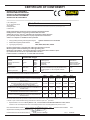
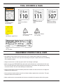
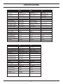
BR40
Thru
BR87
HYDRAULIC BREAKER
SAFETY, OPERATION AND MAINTENANCE
USER'S MANUAL
Read the Manual
Wear your PPE
© Stanley Hydraulic Tools 2004
OPS/MAINT USA / CE
Printed in U.S.A.
71098 10/2009 ver 1
TABLE OF CONTENTS
WARRANTY............................................................................................................................................................... 3
CERTIFICATE OF CONFORMITY............................................................................................................................. 4
SAFETY PRECAUTIONS .......................................................................................................................................... 5
TOOL STICKERS & TAGS ........................................................................................................................................ 7
OPERATION .............................................................................................................................................................. 8
PRE-OPERATION PROCEDURES ........................................................................................................................ 8
CHECK POWER SOURCE .................................................................................................................................... 8
INSTALL TOOL BIT................................................................................................................................................. 8
CONNECT HOSES................................................................................................................................................. 8
COLD WEATHER OPERATION ............................................................................................................................. 8
SPECIFICATIONS ..................................................................................................................................................... 9
WARRANTY
Stanley Hydraulic Tools (hereinafter called “Stanley”), subject to the exceptions contained below, warrants new hydraulic tools for a period of one year from the date of sale to
the first retail purchaser, or for a period of 2 years from the shipping date from Stanley, whichever period expires first, to be free of defects in material and/or workmanship at
the time of delivery, and will, at its option, repair or replace any tool or part of a tool, or new part, which is found upon examination by a Stanley authorized service outlet or by
Stanley’s factory in Milwaukie, Oregon to be DEFECTIVE IN MATERIAL AND/OR WORKMANSHIP.
WARRANTY REGISTRATION: STANLEY ASSUMES NO LIABILITY FOR WARRANTY CLAIMS SUBMITTED FOR WHICH NO TOOL REGISTRATION IS ON RECORD. In
the event a warranty claim is submitted and no tool registration is on record, no warranty credit will be issued without first receiving documentation which proves the sale of the
tool or the tools’ first date of usage within 15 days of sale. The term “DOCUMENTATION” as used in this paragraph is defined as a bill of sale, or letter of intent from the first
retail customer. A WARRANTY REGISTRATION FORM THAT IS NOT ALSO ON RECORD WITH STANLEY WILL NOT BE ACCEPTED AS “DOCUMENTATION”.
NO ADDITIONAL WARRANTIES OR REPRESENTATIONS
This limited warranty and the obligation of Stanley thereunder is in lieu of all other warranties, expressed or implied including merchantability or fitness for a particular purpose
except for that provided herein. There is no other warranty. This warranty gives the purchaser specific legal rights and other rights may be available which might
vary depending upon applicable law.
For additional details on the warranty contact your distributor or call Stanley Hydraulic Tools at the number on the back of this manual and ask for a
Customer Service Representative.
SERVICING THE STANLEY HYDRAULIC breaker. This manual contains safety, operation, and routine
maintenance instructions. Stanley Hydraulic Tools recommends that servicing of hydraulic tools, other
than routine maintenance, must be performed by an authorized and certified dealer. Please read the following warning.
WARNING
SERIOUS INJURY OR DEATH COULD RESULT FROM THE IMPROPER REPAIR OR SERVICE OF THIS TOOL.
REPAIRS AND / OR SERVICE TO THIS TOOL MUST ONLY BE
DONE BY AN AUTHORIZED AND CERTIFIED DEALER.
For the nearest authorized and certified dealer, call Stanley Hydraulic Tools at the number listed on the
back of this manual and ask for a Customer Service Representative.
3
CERTIFICATE OF CONFORMITY
CERTIFICATE OF CONFORMITY
ÜBEREINSTIMMUNGS-ZERTIFIKAT
CERTIFICAT DE CONFORMITE CEE
CERTIFICADO DE CONFORMIDAD
CERTIFICATO DI CONFORMITA
Hydraulic Tools
______________________________________________________________________
I, the undersigned:
Ich, der Unterzeichnende:
Je soussigné:
El abajo firmante:
lo sottoscritto:
Piert, Charlie
Surname and First names/Familiennname und Vornamen/Nom et prénom/Nombre y apellido/Cognome e nome
hereby certify that the construction plant or equipment specified hereunder:
bestätige hiermit, daß das im folgenden genannten Werk oder Gerät:
certifies par ceci que l’ usine ou l’ équipement de construction indiqué cidessous:
por el presente certifico que la fabrica o el equipo especificado a continuacion:
certifico che l’impianto o l’attrezzatura sotto specificata:
1.
Category/Kategorie/Catégorie/Categoria/Categoria:
2.
Make/Ausführung/Marque/Marca/Marca
Stanley
Hydraulic Hand Held Concrete Breaker
3.
Type/Typ/Type/Tipo/Tipo:
BR40, BR45, BR48, BR67, & BR87
Has been manufactured in conformity with - EEC Type examination as shown.
Wurde hergestellt in Übereinstimmung mit - EEC Typ-Prüfung nach.
Est fabriqué conformément - au(x) type(s) examiné(s) comme indiqué dans le tableau ci-après.
Ha sido fabricado de acuerdo con - tipo examen EEC como dice.
E’ stata costruita in conformitá con - le norme CEE come illustrato.
Examen CEE de type
Directive
Richtlinie
Directives particulières
Directriz
Direttiva
EN
Noise Directive
No.
Nr
Numéro
No
n.
792-4
2000/14/EC
Date
Datum
Date
Fecha
Data
2008
2000
Machinery Directive
98/37/EC
1998
Approved body
Prüfung durch
Organisme agréé
Aprobado
Collaudato
Self
SMP Svensk Maskinprovning AB (Notified body)
Fyrisborgsgatan 3, 754 50 Uppsala, Sweden
Self
Date of expiry
Ablaufdatum
Dated´expiration
Fecha de caducidad
Data di scadenza
NA
NA
NA
Measurements/Messungen/Mesures/Mediciones/Misurazioni:
Measured sound power/Gemessener Schallleistungspegel/De
puissance acoustique mesuré/De potencia acústica medido/Di
Potenza sonora
Guaranteed sound power/Garantierte Schallleistung/De
puissance acoustique garanti/De potencia acústica
garantizado/Di Potenza Sonora garantito
Noise related value/ Rauschen im Zusammenhang mit
Wert/Bruit liées valeur/Ruido relacionados con el valor/Rumore
correlate valore.
Year of manufacture/of manufacture/Baujahr/année de
fabrication/Año de fabricacion/Anno di fabbricazione
Serial number of equipment/Seriennummer des Geräts/Numéro
de série de l’équipement/Numero de serie del equipo/Matricola
dell’ attrezzatura:
BR40
BR45
BR48
BR67
BR87
106 LwA
106 LwA
106 LwA
107 LwA
110 LwA
107 LwA
107 LwA
107 LwA
110 LwA
111LwA
21 kg
23 kg
25 kg
31 kg
38 kg
2006
2006
2006
2006
2006
All
All
All
All
All
We declare that it meets the specifications of Noise Directive 2000/14/EC, measured in accordance to the conformity evaluation method set out
nd
in Annex VI para. 5 and evaluated during production as in Annex VI para. 6, 2 procedure.
7.
Representative in the Union: Stanley Dubuis 17-19, rue Jules Berthonneau-BP 3406 41034 Blois Cedex, France.
Vertreter in der union/Représentant dans l’union/Representante en la union/Rappresentante presso l’unione
Done at/Ort/Fait à/Dado en/Fatto a Stanley Hydraulic Tools, Milwaukie, Oregon USA
Date/Datum/le/Fecha/Data
2001
Signature/Unterschrift/Signature/Firma/Firma
Position/Position/Fonction/Puesto/Posizione
Quality Assurance Manager
4
Rev. 1 9/24/2009
SAFETY PRECAUTIONS
WARNING
To avoid seriou s injury o r death
Tool operators and maintenance personnel must always comply with the safety precautions given in this manual and on the stickers and tags attached to the tool and
hose.
These safety precautions are given for your safety. Review them carefully before
operating the tool and before performing general maintenance or repairs.
Supervising personnel should develop additional precautions relating to the specific
work area and local safety regulations. If so, place the added precautions in the space
provided in this manual.
The Hydraulic Breaker will provide safe and dependable service if operated in accordance with the instructions given in this manual. Read and understand this manual
and any stickers and tags attached to the tool and hoses before operation. Failure to
do so could result in personal injury or equipment damage.
•
Operator must start in a work area without bystanders. The operator must be familiar with all prohibited work areas
such as excessive slopes and dangerous terrain conditions.
•
Establish a training program for all operators to ensure safe operation.
•
Do not operate the tool unless thoroughly trained or under the supervision of an instructor.
• Always wear safety equipment such as goggles, gloves, ear, head, and breathing protection, and safety shoes at all times when
operating the tool.
•
Do not inspect, carry or clean the tool while the hydraulic power source is connected. Accidental engagement of the tool can
cause serious injury.
•
Supply hoses must have a minimum working pressure rating of 2500 psi/175 bar. Do not exceed rated working pressure of hydraulic hose used with this tool. Excess pressure may cause a leak or burst.
•
Be sure all hose connections are tight.
•
The hydraulic circuit control valve must be in the “OFF” position when coupling or uncoupling the tool. Wipe all couplers
clean before connecting. Use only lint-free cloths. Failure to do so may result in damage to the quick couplers and cause
overheating of the hydraulic system.
•
Do not operate the tool at oil temperatures above 140°F/60°C. Operation at higher oil temperatures can cause operator
discomfort and may damage the tool. Never come in contact with the tool bit, the bit can get hot.
•
Do not operate a damaged, improperly adjusted, or incompletely assembled tool.
•
Do not weld, cut with an acetylene torch, or hard-face the tool bit.
•
To avoid personal injury or equipment damage, all tool repair, maintenance and service must only be performed by
authorized and properly trained personnel.
•
Do not exceed the rated limits of the tool or use the tool for applications beyond its design capacity.
•
Always keep critical tool markings, such as labels and warning stickers legible.
•
Always replace parts with replacement parts recommended by Stanley Hydraulic Tools.
•
Check fastener tightness often and before each use daily.
•
Never operate the tool if you cannot be sure that underground utilities are not present.
•
Do not wear loose fitting clothing when operating the tool.
5
SAFETY PRECAUTIONS
•
Warning: Hydraulic fluid under pressure could cause skin injection injury. If you are injured by hydraulic fluid, get
medical attention immediately.
•
Keep all body parts away from the working tool.
•
When handling material or the tool bit, wear your (PPE) Personal Protection Equipment.
•
Be observant of the hydraulic hoses lying about the work area, they can be a tripping hazard.
•
Always de-energize the hydraulic system when changing a tool bit.
•
Take caution when changing a tool bit, tool bits can get very hot.
•
Never use the tool in an explosive atmosphere, sparks from the breaking process could ignite explosive gas.
•
Use proper lifting techniques when handling the tool, get help from a co-worker and do not over-reach.
•
Use proper protection from falling or flying debris, keep bystanders at a safe distance.
•
Do not exceed the rated flow and pressure. See Specifications in this manual for correct flow rate and
pressure rating. Rapid failure of the internal seals may result.
•
Failure to use hydraulic hose labeled and certified as non-conductive when using hydraulic tools on or near electric
lines may result in death or serious injury.
•
Handle and route hose carefully to avoid kinking, abrasions, cutting, or contact with high temperature surfaces. Do
not use hose to pull or lift tools, power units, etc.
•
Check entire hose for cuts, cracks, leaks, abrasions, bulges, or damage to couplings if any of these conditions exist,
replace the hose immediately. Never use tape or any device to attempt to mend the hose.
•
Do not use conductive hose on or near electric lines. This hose is not labeled or certified as non-conductive. Using
this hose on or near electrical lines may result in death or serious injury.
WARNING
Exposure to crystalline Silica (sometimes called “silica dust”) as a result of
breaking, drilling, or hammering of rock, concrete, asphalt or other materials may cause Silicosis (a serious lung disease), silicosis-related illnesses,
cancer, or death.
Respiratory protection is highly recommended when working with materials
containing Silica Dust.
Always wear a respirator approved for protection against crystalline silica.
6
TOOL STICKERS & TAGS
WARNING
To avoid seriou s injury o r death
LWA
LWA
LWA
110
111
107
66656
Sound Level Decal
BR87
58601
Sound Level Decal
BR40, BR45, BR48
58604
Sound Level Decal
BR67
28409
Composite Decal
CE Tool Only
11208
Hex Shank Length Decal
11206
Circuit Type C Decal
CE Tool Only
11207
Circuit Type D Decal
CE Tool Only
71072
CE Tool Plate
EQUIPMENT PROTECTION & CARE
• The hydraulic circuit control valve must be in the “OFF” position when coupling or uncoupling
hydraulic tools. Failure to do so may result in damage to the quick couplers and cause overheating
of the hydraulic system.
• Always store the tool in a clean dry space, safe from damage or pilferage.
• Make sure the circuit PRESSURE hose (with male quick disconnect) is connected to the “IN” port.
The circuit RETURN hose (with female quick disconnect) is connected to the opposite port. Do not
reverse circuit flow. This can cause damage to internal seals.
• Keep tool bit sharp for maximum breaker performance. Make sure that tool bits are not chipped or
rounded on the striking end.
• Never operate a breaker without a tool bit or without holding it against the work surface. This puts
excessive strain on the breaker foot.
• Make certain that the recommended relief valves are installed in the pressure side of the system.
7
OPERATION
3. Place the bit firmly on the surface to be broken.
The recommended hose size is .500 inch/12 mm I.D. up to
50 ft/15 m long and .625 inch/16 mm I.D. minimum up to 100
ft/30 m.
4. Squeeze the trigger to start the breaker. Adequate down
pressure is very important. When the tool bit breaks through
the obstruction or becomes bound, release the trigger and
reposition the tool bit.
PRE-OPERATION PROCEDURES
CHECK POWER SOURCE
NOTE:
Partially depressing the trigger allows the tool to run at
slow speed. Slow-speed operation permits easier starting
of the tool bit into the work surface.
1. Using a calibrated flowmeter and pressure gauge, check
that the hydraulic power source develops a flow of 7-9 gpm/2634 lpm at 1500-2000 psi/105-140 bar or 4-6 gpm/15-23 lpm
at 1300 psi/90 bar depending on your model
5. To start, break an opening (hole) in the center of the surface.
After making a hole, break portions of the material into the
original opening. For best productivity, the breaking should
be done around the original hole.
2. Make certain the hydraulic power source is equipped
with a relief valve set to open at 2100-2250 psi/144-155 bar
maximum.
The size of the broken material will vary with the strength
and thickness of the base material and the amount of any
reinforcement wire or rebar.
INSTALL TOOL BIT
1. Rotate the latch on the breaker foot downward (pointing
away from the tool).
Harder material or more reinforcing wire or rebar will require
taking smaller bites. To determine the most effective bite, start
with 2 in. / 50 mm or smaller bites.
2. Insert the tool bit into the foot and pull the latch up to lock
the tool bit in place.
Bites can then be gradually increased until the broken piece
becomes too large, requiring increased time to break off the
piece.
CONNECT HOSES
1. Wipe all hose couplers with a clean, lint-free cloth before
making connections.
Sticking of the tool bit occurs when too large a bite is being
taken and the tool bit hammers into the material without the
material fracturing. This causes the tool bit to become trapped
in the surrounding material.
2. Connect the hoses from the hydraulic power source to the
tool fittings or quick disconnects. It is a good practice to connect return hoses first and disconnect them last to minimize
or avoid trapped pressure within the tool.
COLD WEATHER OPERATION
3. Observe flow indicators stamped on hose couplers to
ensure that fluid flow is in the proper direction. The female
coupler on the tool hose is the inlet coupler.
If the breaker is to be used during cold weather, preheat the
hydraulic fluid at low engine speed. When using the normally
recommended fluid, fluid temperature should be at or above
50° F/10° C (400 ssu/82 centistokes) before use.
4. Move the hydraulic circuit control valve to the ON position
to operate the tool.
Damage to the hydraulic system or breaker can result from
use with fluid that is too viscous or thick.
NOTE:
If uncoupled hoses are left in the sun, pressure increase
within the hoses may make them difficult to connect.
When possible, connect the free ends of the hoses together.
OPERATION PROCEDURES
1. Observe all safety precautions.
2. Install the appropriate tool bit for the job.
8
SPECIFICATIONS
Flow Range
BR40
1300-2000 psi /
90-140 bar
4-6 gpm / 15-23 lpm
BR45
1500-2000 psi /
105-140 bar
7-9 gpm / 26-34 lpm
Optimum Flow
5-gpm / 20 lpm
8-gpm / 30 lpm
Maximum Back Pressure
Couplers
Connect Size
Weight (T Handle)
(Anti-Vibration Handle)
Overall Length (T-Handle)
(Anti-Vibration Handle)
Overall Width (T-Handles)
(Anti-Vibration Handle)
Max. Fluid Temperature
System Type
Port Size
EHTMA Category
Type C, Type D
Filtering (Hydraulic Oil)
System Relief Valve Setting
Guaranteed Sound Power
Level (2000/14/EC)
Sound Pressure Level
1 Meter (ISO 11203)
Vibration Level (ISO 8662-5)
Tee Handle
Anti-Vibration Handle
250 psi / 17 bar
HTMA Flush Face
3/8 Male Pipe Hose End
41 lbs / 18 kg
44 lbs / 20 kg
23.5 in / 60 cm
25.2 in / 65 cm
14 in / 35 cm
17.5 in / 44.5 cm
140°F / 60° C
Open Center
SAE -8 O’ring
250 psi / 17 bar
HTMA Flush Face
3/8 Male Pipe Hose End
45/48 lbs / 20/21 kg
48/51 lbs / 22/23 kg
23.5/25.5 in / 60/65 cm
25.2/28.25 in / 65/72 cm
14 in / 35 cm
17.5 in / 44.5 cm
140°F / 60° C
Open Center
SAE -8 O’ring
Type C
25 Microns
2100-2250 psi
Type D
25 Microns
2100-2250 psi
140°F / 60° C
Open Center
SAE -8 O’ring
Type C
Type D
25 Microns
2100-2250 psi
107 dBA
107 dBA
107 dBA
98 dBA
98 dBA
98 dBA
10.0 m/sec²
9.2 m/sec²
13.5 m/sec²
10.1 m/sec²
9.9 m/sec²
BR67
1500-2000 psi /
105-140 bar
7-9 gpm / 26-34 lpm
8-gpm / 30 lpm
250 psi / 17 bar
HTMA Flush Face
3/8 Male Pipe Hose End
67 lbs / 30 kg
75 lbs / 34 kg
27 in / 69 cm
29 in / 74 cm
16 in / 41 cm
18 in / 46 cm
140°F / 60° C
Open Center
SAE -8 O’ring
BR87
1500-2000 psi /
105-140 bar
7-9 gpm / 26-34 lpm
8-gpm / 30 lpm
250 psi / 17 bar
HTMA Flush Face
3/8 Male Pipe Hose End
80 lbs / 36 kg
N/A
27 in / 68 cm
N/A
16 in / 40 cm
N/A
140°F / 60° C
Open Center
SAE -8 O’ring
Type D
25 Microns
2100-2250 psi
Type D
25 Microns
2100-2250 psi
110 dBA
111 dBA
99 dBA
102 dBA
20 m/sec²
10.2 m/sec²
21.5 m/sec²
N/A
Pressure Range
Pressure Range
Flow Range
Optimum Flow
Maximum Back Pressure
Couplers
Connect Size
Weight (T Handle)
(Anti-Vibration Handle)
Overall Length (T-Handle)
(Anti-Vibration Handle)
Overall Width (T-Handles)
(Anti-Vibration Handle)
Max. Fluid Temperature
System Type
Port Size
EHTMA Category
Type C, Type D
Filtering (Hydraulic Oil)
System Relief Valve Setting
Guaranteed Sound Power
Level (2000/14/EC)
Sound Pressure Level
1 Meter (ISO 11203)
Vibration Level (ISO 8662-5)
Tee Handle
Anti-Vibration Handle
9
BR48
1500-2000 psi /
105-140 bar
7-9 gpm / 26-34 lpm
4-6 gpm / 15-23 lpm
8-gpm / 30 lpm
5-gpm / 20 lpm
250 psi / 17 bar
HTMA Flush Face
3/8 Male Pipe Hose End
55 lbs / 25 kg
28.5 in / 72.4 cm
17.25 in / 44 cm
Stanley Hydraulic Tools
3810 SE Naef Road
Milwaukie, Oregon
503-659-5660 / Fax 503-652-1780
www.stanleyhydraulic.com
10