1
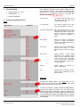
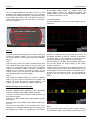
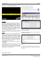
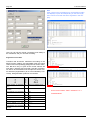
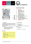
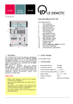
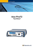
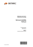
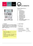
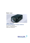
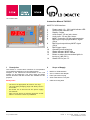
10/14-W2010-Wei Instruction Manual 740 2013 1 2 3 4 5 6 MOST PC USB Interface 7 8 9 10 14 Power supply, 10 – 20 V= with indicator LED USB port with indicator LED Display, 5 digits Audio output, 3.5 mm jack, stereo Audio input, 3.5 mm jack, stereo MOST connection for fiber optic connector BNC signal output physical MOST signal (50 ) BNC signal output binary MOST signal (50 ) BNC trigger output Operating mode select key Status indicator: MOST light Status indicator: MOST locked Button to reduce the transmitted light's intensity to 3 dB (50 %) Status LED for pos. 13 2 Scope of Supply 1 2 3 4 5 6 7 8 9 10 11 12 13 1 Description This device is a menu-driven interface for incorporation into a MOST25 network to log and analyze data. Analysis of the transferred communication in the real system can be interactive. The Trace, Data and Audio window functions with filter function are available for this purpose. Safety notes MOST PC USB interface 230 V, 50/60 Hz AC adapter Fiber optic with one plug Audio cable with 3.5 mm jack USB connecting lead - The device is appropriate for interior use only! - Use only safety bridging plugs and safety connection leads! - Be careful not to short-circuit the power supply. Fire hazard! - Only use the device for training purposes. Installation in an actual vehicle is prohibited! LD DIDACTIC GMBH • Leyboldstrasse 1 • D-50354 Huerth / Germany • Phone +49 (0)2233 604-0 • Fax +49(0)2233 604-222 • E-Mail: [email protected] © by LD Didactic GmbH Printed in the Federal Republic of Germany Technical alterations reserved Instruction Manual 3 Upon startup (connection to the power supply), the device performs a self test – during which the display completely fills up. At the end of this test, the message " " displays for approx. 3 seconds and then first menu item, " " Technical Data 4 Page 2/5 Supply voltage: 10 – 20 V~ USB interface: 1.1 Protocol: MOST25 Setup and Function Check Phy. Node Pos. The device's physical position in the ring, starting from the master clock (usually the Head Unit). Log. Node Addr. The device's address with which other bus subscribers can reach it. Synchronous Bandwidth Per the MOST protocol for the "Boundary descriptor," so the limit between the synchronous and asynchronous areas, the display indicates the number of quadlets (4 bytes). Audio Output This lets you select a synchronous channel for MOST transmission, which is then output at the device's analog audio output. Audio Input This lets you activate and define the device's audio input, on which MOST channel to transfer the signal fed. Block Trigger Defines whether a trigger signal generates at the device's trigger output for every single MOST frame or only for every 16th. In the latter case, a trigger signal is generated for every first frame in a 16-byte control data sequence. Capture Defines whether to examine the input or output signal. Info Indicates device information (name, article number, hardware and software versions). Menu Main menu Submenu Operation Pressing the MODE button (10) briefly lets you run through all main menu items. After the last menu item, the sequence returns to the first one. To shift into submenus, press and hold the MODE button (10) until the display (3) blinks. You can now browse through the submenu's individual entries by briefly pressing the MODE button (10) again. Adopt the selected value by pressing and holding the MODE button (10) again until the main menu entry appears again and the display stops blinking. LD DIDACTIC GMBH Leyboldstrasse 1 D-50354 Huerth / Germany Phone +49 (0)2233 604-0 Fax +49 (0)2233 604-222 e-mail: [email protected] by LD Didactic GmbH Printed in the Federal Republic of Germany Technical alterations reserved Page 3/5 Instruction Manual You can display additional information for use in Audi systems if the analyzer integrates the ring by pressing and holding the [Setup] function key along with the [Return] function key until the list of all MOST devices appears. Select the analyzer and press "Entry." The following screen appears: IRC LD MOST Analyzer al messages ("Block trigger on" setting). Select the "Block trigger" display by repeatedly pressing the "MODE" button (10). Press and hold the "MODE" button to switch this function on or off. Individual message Scale the time axis so you can recognize about 20 individual bits. MOST Devicename: LD MOST Analy... SW-Nummer: 7402013 SW-Index: 1.02 SW-Date: 30.07.09 HW-Number: 7402013 HW-Index: 038 Parameter TP TMC 4-R On/Off Startup Step 1 Plug the enclosed power supply into a power socket and connect the cable to socket 1. The "15 V OK" LED lights up, and an indicator continuously scrolls through the display (3). Step 2 Insert the plug at the end of the enclosed orange fiber optic cable into fiber optic socket 6. Plug the two loose ends of the orange fiber optic cable into the plexiglass coupler on the MOST systems 740 2010, 740 2012 or 739 5841. If you wish to use another system, e.g. an original vehicle, you must produce a fiber optic adapter, e.g. using parts from the set 740 20821. Step 3 Now switch the MOST system on. Press the "MODE" button (10) once. Upon a successful ring formation, the display (3) shows the device's network address. The "LIGHT" (11) and "LOCKED" (12) LED's also light up. MOST messages on an oscilloscope Basic settings Connect a digital storage oscilloscope with a bandwidth of at least 100 MHz using 3 BNC cables as follows: Channel 1 on BNC socket "MOST Signal Physical" (7) [physical bus signal] Channel 2 on BNC socket "MOST Signal Binary" (8) [binary signal] External trigger input on BNC socket "MOST Signal Trigger" (9) You now have the option to set a trigger either at the beginning of a message ("Block trigger off" setting) or at the beginning of a "block," i.e. a sequence of 16 individu- Channel 1 represents the light signals on the bus, so essentially switching on and off. Channel 2 represents the binary data, so the sequence of zeros and ones, which the processor in the control unit must analyze. Connect Channel 1 to BNC socket "MOST Signal Trigger" (9) and change the trigger setting on the oscilloscope to "Channel 1." Scale the time axis so you see a complete message. The voltage change in the trigger signal indicates the end of the message's synchronous range and therefore the beginning of its asynchronous range. You can display the length in bytes in menu item 3, "Synchronous Bandwidth." Block Now change the trigger setting to "Block trigger" following the description above. Also change the time axis so you Instruction Manual can just see two trigger signals. Exactly 16 individual messages are now recognizable between them. Page 4/5 Install the software by running Setup. Recording the MOST control data Begin recording the data by pressing the button Audio signals Decoupling Integrate the device right before the audio amplifier in the MOST ring, following the description above. Connect a pair of simple PC loudspeakers to the "Audio out" socket (4). Now select item "Audio output" in the menu by repeatedly pressing the "MODE" button (10). Press and hold the "MODE" button (10) until the display blinks and then press the "MODE" button (10) again as often as necessary until "Ch 0" appears in the display (3). Finally, press the "MODE" button (10) once more. If you now play audio data, e.g. radio, in the MOST system, you can also hear the sound through the PC loud speakers. Coupling Connect an audio source, such as an MP3 player, to the "Audio in" socket (5) and start the playback. Your MOST system also lets you play back audio data like the radio. Now select item "Audio input" in the menu by repeatedly pressing the "MODE" button (10). Press and hold the "MODE" button (10) until the display blinks and then press the "MODE" button (10) again as often as necessary until "Ch 0" appears in the display (3). Finally, press the "MODE" button (10) once more. Your MOST system now plays back the audio data from the MP3 player. Light reduction To find critical positions in the fiber optic ring, the transmitted light's intensity can be reduced. Press the "-3 dB ON/OFF" button (13) for this. A red LED (14) indicates this function is on. The light's intensity then nearly gets halved [-3 dB = 10^(-3/10) = 0.501] Additional information Click on a line! The lower portion of the window displays explanations for the data! Filter To record precise messages from or to a particular control unit, or a particular type of message, you can use the filter dialog: MOST diagnosis software LD DIDACTIC GMBH Leyboldstrasse 1 D-50354 Huerth / Germany Phone +49 (0)2233 604-0 Fax +49 (0)2233 604-222 e-mail: [email protected] by LD Didactic GmbH Printed in the Federal Republic of Germany Technical alterations reserved Page 5/5 Instruction Manual Note After a click on the message's line, the transferred radio text displays in plain text! Depending on the text length, there can be more than the three segments in this display! Here you can set the criteria a message must satisfy to be considered, and you can start recording. Segmented control data = Data 0 Message Count Telegram ID Meaning Transfers that should be transferred according to the MOST function catalog, are transmitted using the control channel and correspondingly designated as control transfers. But since only 17 bytes of the control channel are user data, a transfer with more than 12 bytes of parameter data to be transmitted must be split into several control transfers (segmentation) to be sent individually. Conversely, desegmentation produces one transfer. Single transfer, no segmentation 0 Data 0 (no message count) 1st telegram of a segmented transfer 1 0x00 2nd telegram of a segmented transfer 2 0x01 … 2 … … 2 0xFF … 2 0x00 … 2 … (n-1)th telegram of a segmented transfer 2 0x(n-1) Last telegram of a segmented transfer 3 0xn So the full text reads: "Rad"+"iofeuilleto"+"n" = "Radiofeuilleton"