1
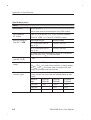
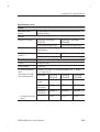
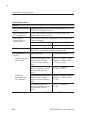
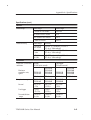
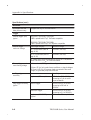
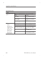
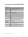
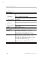
Appendix A: Specifications
This appendix contains specifications for the TDS3000B Series
oscilloscopes. All specifications are guaranteed unless noted as
“typical.” Typical specifications are provided for your convenience
but are not guaranteed. Specifications that are marked with the
n symbol are checked in Appendix E: Performance Verification.
All specifications apply to all TDS3000B Series models unless noted
otherwise. To meet specifications, two conditions must first be met:
H The oscilloscope must have been operating continuously for
twenty minutes within the operating temperature range specified.
H You must perform the Compensate Signal Path operation
described on page 1–4. If the operating temperature changes by
more than 10° C, you must perform the Compensate Signal Path
operation again.
Specifications
Acquisition
Acquisition modes
Sample (Normal), Peak detect, Envelope, and Average
Single Sequence
Acquisition mode
Acquisition stops after
Sample, Peak Detect
One acquisition, all channels
simultaneously
Average, Envelope
N acquisitions, all channels
simultaneously, N is settable
from 2 to 256 (or ∞ for Envelope)
With compliments
Helmut Singer Elektronik
www.helmut-singer.de [email protected]
fon +49 241 155 315
fax +49 241 152 066
Feldchen 16-24 D-52070 Aachen Germany
TDS3000B Series User Manual
A–1
Appendix A: Specifications
Specifications (cont.)
Inputs
Input coupling
DC, AC, or GND
Channel input remains terminated when using GND coupling.
Input impedance,
DC coupled
1 MW ±1% in parallel with 13 pF ±2 pF, TekProbe compatible
Maximum voltage at
input BNC (1 MW)
W)
Overvoltage category
Maximum voltage
CAT I Environment (refer to
page A–14)
150 VRMS (400 Vpk)
CAT II Environment (refer to
page A–14)
100 VRMS (400 Vpk)
50 W ±1%; VSWR ≤ 1.5:1 from DC to 500 MHz, typical
For steady-state sinusoidal waveforms, derate at 20 dB/decade
above 200 kHz to 13 Vpk at 3 MHz and above.
Maximum voltage at
input BNC (50 W)
5 VRMS with peaks ≤ ±30 V
Maximum floating
voltage
0 V from chassis (BNC) ground to earth ground, or
Channel-to-channel
crosstalk, typical
A–2
30 VRMS (42 Vpk) only under these conditions: no signal voltages
>30 VRMS (>42 Vpk), all common leads connected to the same
voltage, no grounded peripherals attached
Measured on one channel, with test signal applied to another
channel, and with the same scale and coupling settings on each
channel
Frequency
range
TDS3012B
TDS3014B
TDS3032B
TDS3034B
TDS3052B
TDS3054B
≤ 100 MHz
≥ 100:1
≥ 100:1
≥ 100:1
≤ 300 MHz
—
≥ 50:1
≥ 50:1
≤ 500 MHz
—
—
≥ 30:1
TDS3000B Series User Manual
Appendix A: Specifications
Specifications (cont.)
Inputs
Differential delay,
typical
100 ps between any two channels with the same scale and
coupling settings
Vertical
Number of channels
TDS3012B, TDS3032B,
TDS3052B
TDS3014B, TDS3034B,
TDS3054B
2 plus external trigger input
4 plus external trigger input
Digitizers
9-bit resolution, separate digitizers for each channel, sampled
simultaneously
SCALE Range
(at BNC)
1 MW
50 W
1 mV/div to 10 V/div
1mV/div to 1 V/div
Fine SCALE
Adjustable with ≥ 1% resolution
Polarity
Normal and Invert
Position range
±5 divisions
n Analog bandwidth,
50 W
(also typical at 1 MW
with standard probe)
Bandwidth limit set to Full, operating ambient ≤30 °C, derate
1%/°C above 30 °C
Scale range
TDS3012B
TDS3014B
TDS3032B
TDS3034B
TDS3052B
TDS3054B
5 mV/div to
1 V/div
100 MHz
300 MHz
500 MHz
2 mV/div to
4.98 mV/div
100 MHz
250 MHz
300 MHz
1 mV/div to
1.99 mV/div
90 MHz
150 MHz
175 MHz
3.5 ns
1.2 ns
0.7 ns
Calculated rise time, —
typical
TDS3000B Series User Manual
A–3
Appendix A: Specifications
Specifications (cont.)
Vertical
Analog bandwidth limit, Selectable between 20 MHz, 150 MHz (not available on
typical
TDS3012B or TDS3014B), or Full
Lower frequency limit,
AC coupled, typical
7 Hz for 1 MW, reduced by a factor of ten when using a 10X
passive probe; 140 kHz for 50 W
Peak detect or
Envelope pulse response, typical
Minimum width of pulse with amplitude of ≥2 div to capture 50%
or greater amplitude
Sample rates ≤125 MS/s
Sample rates ≥250 MS/s
1 ns
1/sample rate
DC gain accuracy
± 2%, derated at 0.025%/°C for temperatures below +18° C and
above +30° C, in Sample or Average acquisition mode
DC measurement
accuracy
Measurement type
DC Accuracy (in volts)
Absolute measurement of any
waveform point, and High,
Low, Max, and Min measurements.
± [0.021 | reading – (offset
– position) | + offset accuracy
+ 0.15 div + 0.6 mV]
Delta voltage between any two
points on a waveform, and all
other automatic measurements.
± [0.021 | reading | +
0.15 div + 1.2 mV]
Absolute measurement of any
waveform point, and High,
Low, Max, and Min measurements.
± [0.021 | reading – (offset
– position) | + offset accuracy
+ 0.1 div]
Delta voltage between two
points on a waveform, and all
other automatic measurements.
± [0.021 | reading | +
0.05 div]
Sample acquisition
mode, typical
n Average
acquisition mode
(≥16 averages)
1
A–4
0.02 term (gain component) derated at 0.00025/°C above 30° C
TDS3000B Series User Manual
Appendix A: Specifications
Specifications (cont.)
Vertical
Offset range
Offset Accuracy
Scale range
Offset range
1 mV/div to 9.95 mV/div
±100 mV
10 mV/div to 99.5 mV/div
±1 V
100 mV/div to 995 mV/div
±10 V
1 V/div to 10 V/div
±100 V
Scale range
Accuracy
1 mV/div to
100 mV/div
± [0.002 | net offset | +1.5 mV +
(0.1 div V/div setting)]
101 mV/div to
1 V/div
± [0.0025 | net offset | +15 mV +
(0.1 div V/div setting)]
1.01 V/div to
10 V/div
± [0.0025 | net offset | +150 mV +
(0.1 div V/div setting)]
Horizontal
Acquisition (horizontal)
resolution
Normal
(10,000 point record)
Fast trigger
(500 point record)
TDS3012B
TDS3014B
TDS3032B
TDS3034B
TDS3052B
TDS3054B
TDS3012B
TDS3014B
TDS3032B
TDS3034B
TDS3052B
TDS3054B
400 wfms/s
700 wfms/s
2,600 wfms/s
3,600 wfms/s
TDS3012B
TDS3014B
TDS3032B
TDS3034B
TDS3052B
TDS3054B
Normal
100 S/s to
1 GS/s
100 S/s to
2.5 GS/s
100 S/s to
5 GS/s
Fast trigger
5 S/s to
1.25 GS/s
5 S/s to
2.5 GS/s
5 S/s to
5 GS/s
Seconds/division
range
4 ns/div to
10 s/div
2 ns/div to
10 s/div
1 ns/div to
10 s/div
Maximum
acquisition rate,
typical
Sample rate range
TDS3000B Series User Manual
A–5
Appendix A: Specifications
Specifications (cont.)
Horizontal
n Sample rate and
delay time accuracy
±20 ppm over any ≥1 ms time interval
Trigger
External trigger input,
typical
TDS3012B, TDS3032B, TDS3052B:
1 MW in parallel with 17 pF, TekProbe compatible
TDS3014B, TDS3034B, TDS3054B:
1 MW in parallel with 52 pF, not Tekprobe compatible
External trigger
maximum voltage
Overvoltage category
Maximum voltage
CAT I Environment (refer to
page A–14)
150 VRMS (400 Vpk)
CAT II Environment (refer to
page A–14)
100 VRMS (400 Vpk)
For steady-state sinusoidal waveforms, derate at 20 dB/decade
above 200 kHz to 13 Vpk at 3 MHz and above.
External trigger maximum floating voltage
n Edge trigger
sensitivity
Edge trigger sensitivity,
typical
A–6
0 V from chassis (BNC) ground to earth ground, or
30 VRMS (42 Vpk) only under these conditions: no signal voltages
>30 VRMS (>42 Vpk), all common leads connected to the same
voltage, no grounded peripherals attached
Source
Sensitivity
Any channel, DC coupled
0.35 div from DC to 50 MHz,
increasing to 1 div at oscilloscope bandwidth
External trigger
100 mV from DC to 50 MHz,
increasing to 500 mV at
300 MHz
External/10 trigger
500 mV from DC to 50 MHz,
increasing to 3 V at 300 MHz
Any channel, NOISE REJ
coupled
3.5 times the DC-coupled limits
TDS3000B Series User Manual
Appendix A: Specifications
Specifications (cont.)
Trigger
Edge trigger sensitivity,
typical
Trigger level range
Any channel, HF REJ coupled
1.5 times the DC-coupled limit
from DC to 30 kHz, attenuates
signals above 30 kHz
Any channel, LF REJ coupled
1.5 times the DC-coupled limits
for frequencies above 80 kHz,
attenuates signals below
80 kHz
Source
Sensitivity
Any channel
±8 divisions from center of
screen, ±8 divisions from 0 V if
LF REJ trigger coupled
External external
±800 mV
External/10 trigger
±8 V
Line
Fixed at the midlevel of the AC
line
SET LEVEL TO 50%,
typical
Operates with input signals ≥45 Hz
Trigger level accuracy,
typical
Source
Sensitivity
Any channel
±0.2 divisions
External trigger
±20 mV
External/10 trigger
±200 mV
Line
N/A
Trigger holdoff range
250.8 ns to 10 s
TDS3000B Series User Manual
A–7
Appendix A: Specifications
Specifications (cont.)
Trigger
Video trigger sensitivity, Triggers on negative sync of NTSC, PAL, or SECAM signal
typical
Sensitivity
Source
Any channel
0.6 to 2.5 divisions of video
sync tip
External trigger
150 mV to 625 mV of video
sync tip
External/10 trigger
1.5 V to 6.25 V of video sync
tip
Trigger After Time
Trigger After B Events
Range
13.2 ns to 50 s
1 event to 9,999,999 events
Minimum time
between arm and
trigger, typical
5ns from the end of the time
period and the B trigger event
5 ns between the A trigger
event and the first B trigger
event
Minimum Pulse
Width, typical
—
B event width, 2 ns
Maximum Frequency, typical
—
B event frequency, 250 MHz
B Trigger
A–8
TDS3000B Series User Manual
Appendix A: Specifications
Specifications (cont.)
Display
Display screen
6.5 in (165 mm) diagonal color liquid crystal
Display resolution
640 horizontal by 480 vertical pixels
Backlight intensity,
typical
200 cd/m2
Display color
Up to 16 colors, fixed palette
External display filter
Scratch-resistant tempered glass
I/O ports
Ethernet port
10BaseT RJ-45 female connector (all models)
Parallel printer port
Centronics compatible, DB-25 female connector
GPIB interface
Available in optional accessory TDS3GV
RS-232 interface
DB-9 male connector, available in optional accessory TDS3GV,
TDS3EM
VGA signal output
DB-15 female connector, 31.6 kHz sync rate, EIA RS-343A
compliant, available in optional accessory TDS3GV
Probe compensator
output, typical
5.0 V into ≥1 MW load,
frequency = 1 kHz
Miscellaneous
Nonvolatile memory
Typical retention time ≥ 5 years for front-panel settings, unlimited
for saved waveforms and setups
Floppy disk
3.5 in, DOS format, 720 KB or 1.44 MB compatible
Internal clock
Provides date/time stamp for stored data and the current time
and date to the front panel, if enabled.
TDS3000B Series User Manual
A–9
Appendix A: Specifications
Specifications (cont.)
Power sources
AC line power
Operates the oscilloscope and charges the optional internal
battery
Source voltage
90 VRMS to 250 VRMS, continuous range
Source frequency
47 Hz to 440 Hz
Power consumption
75 W maximum
Battery power
Operating time,
typical
Optional accessory TDS3BATNIMH, rechargeable NiMH battery
pack
2 hours, depending on operating conditions
Battery charge time, 18 hours in the oscilloscope, 3 hours in the optional external
typical
charger TDS3CHG
Line fuse
Internal, not user replaceable
Environmental
Temperature
Operating range (no disk installed): +5 °C to +50 °C
Nonoperating range (no disk installed): –20 °C to +60 °C
Typical operating range for floppy disks: +10 °C to +50 °C
Humidity
Operating range (no disk installed): 20% to 80% RH below
32 °C, derate upper limit to 21% RH at 50 °C
Nonoperating range (no disk installed): 5% to 90% RH below
41 °C, derate upper limit to 30% RH at 60 °C
Typical operating range for floppy disks: 20% to 80% RH below
32 °C, derate upper limit to 21% RH at 50 °C
Pollution Degree
A–10
Pollution Degree 2: Typical home or office environment
TDS3000B Series User Manual
Appendix A: Specifications
Specifications (cont.)
Environmental
Altitude
Operating limit: 3000 m
Nonoperating limit: 15,000 m
Random vibration
Operating: 0.31 gRMS from 5 Hz to 500 Hz, 10 minutes on each
axis
Nonoperating: 2.46 gRMS from 5 Hz to 500 Hz, 10 minutes on
each axis
Drop resistance, typical Survives a 152 mm (6 in) drop onto concrete with only cosmetic
damage
Mechanical
Size
Height: 176 mm (6.9 in), 229 mm (9.0 in) including handle
Width: 375 mm (14.75 in)
Depth: 149 mm (5.9 in)
Weight
Oscilloscope only: 3.2 kg (7.0 lbs)
With accessories and carry case: 4.1 kg (9.0 lbs)
When packaged for domestic shipment: 5.5 kg (12.0 lbs)
Optional battery pack: 2.4 kg (5.2 lbs)
TDS3000B Series User Manual
A–11
Appendix A: Specifications
Specifications (cont.)
EMC certifications and compliances
EMC Compliance:
European Union
Meets the intent of Directive 89/336/EEC for Electromagnetic
Compatibility. Compliance was demonstrated to the following
specifications as listed in the Official Journal of the European
Communities:
EN 61326
EMC requirements for Class A electrical equipment for
measurement, control, and laboratory use 1,2
IEC 61000-4-2
Electrostatic discharge immunity (Performance criterion B)
IEC 61000-4-3
RF electromagnetic field immunity (Performance
criterion B)3
IEC 61000-4-4
Electrical fast transient/burst immunity (Performance
criterion B)
IEC 61000-4-5
Power line surge immunity (Performance criterion B)
IEC 61000-4-6
Conducted RF immunity (Performance criterion B)4
IEC 61000-4-11
Voltage dips and interruptions immunity (Performance
criterion B)
EN 61000-3-2
AC power line harmonic emissions
A–12
TDS3000B Series User Manual
Appendix A: Specifications
Specifications (cont.)
EMC certifications and compliances
EMC Compliance:
Australia/New Zealand
Meets the intent of Australian EMC Framework as demonstrated
to the following specification:
AS/NZS 2064.1/2
EMC Compliance:
Russia
This product was certified by the GOST ministry of Russia to be
in compliance with all applicable EMC regulations.
FCC Compliance:
U.S.A.
Emissions comply with FCC Code of Federal Regulations 47,
Part 15, Subpart B, Class A Limits
1
Emissions that exceed the levels required by this standard may occur when
this equipment is connected to a test object.
2
To ensure compliance to the standards listed above, attach only high
quality shielded cables to this instrument. High quality shielded cables
typically are braid and foil types that have low impedance connections to
shielded connectors at both ends.
3
The increase in trace noise while subjected to a test field (3 V/m over the
frequency range 80 MHz to 1 GHz, with 80% amplitude modulation at 1 kHz)
is not to exceed 6 major dvisions peak-to-peak. Ambient conducted fields
may induce triggering when the trigger threshold is offset less than 3 major
divisions from ground reference.
4
The increase in trace noise while subjected to a test field (3 V/m over the
frequency range 150 kHz to 80 MHz, with 80% amplitude modulation at
1 kHz) is not to exceed 4 major dvisions peak-to-peak. Ambient conducted
fields may induce triggering when the trigger threshold is offset less than
2 major divisions from ground reference.
TDS3000B Series User Manual
A–13
Appendix A: Specifications
Specifications (cont.)
Safety certifications and compliances
EC Declaration of
Conformity – Low
Voltage
Compliance was demonstrated to the following specification as
listed in the Official Journal of the European Communities:
Low Voltage Directive 73/23/EEC as ammended by 93/68/EEC
(TDS3000B Series,
P3010, and
P6139A)
EN 61010-1/A2:1995
Safety requirements for electrical equipment for
measurement, control, and laboratory use
(P3010 and
P6139A)
EN 61010-2-031:1995
Particular requirements for hand-held probe assemblies
for electrical measurement and test equipment
Approvals
(TDS3000B Series,
P3010, and
P6139A)
UL3111-1 – Standard for electrical measuring and test equipment
CAN/CSA C22.2 No. 1010.1 – Safety requirements for electrical
equipment for measurement, control and laboratory use
(P3010 and
P6139A)
EN 61010-2-031:1995 – Particular requirements for hand-held
probe assemblies for electrical measurement and test equipment
Installation Category
Descriptions
Terminals on this product may have different installation category
designations. The installation categories are:
CAT III
Distribution-level mains (usually permanently
connected). Equipment at this level is typically in a
fixed industrial location
CAT II
Local-level mains (wall sockets). Equipment at this
level includes appliances, portable tools, and similar
products. Equipment is usually cord-connected
CAT I
Secondary (signal level) or battery operated circuits of
electronic equipment
With compliments
Helmut Singer Elektronik
www.helmut-singer.de [email protected]
fon +49 241 155 315
fax +49 241 152 066
Feldchen 16-24 D-52070 Aachen Germany
A–14
TDS3000B Series User Manual