1
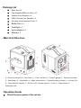
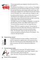
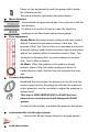
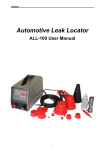
SMOKE ALL-300 Automotive Leak Locator User Manual All the items on this user manual have been checked carefully. About any printing fault or misunderstand, please contact our company. J&L Techno reserve the right of improvement on the product, or change product design without prior notice. Trademark Information J&L Techno is a registered trademark of J&L Techno Ltd. (short for J&L Techno) in China and other countries. All other J&L Techno trademarks, service marks, domain names, logos, and company names referred to in this manual are either trademarks, registered trademarks, service marks, domain names, logos, company names of or are otherwise the property of J&L Techno or its affiliates. In countries where any of the J&L Techno trademarks, service marks, domain names, logos and company names are not registered, J&L Techno claims other rights associated with unregistered trademarks, service marks, domain names, logos, and company names. Other products or company names referred to in this manual may be trademarks of their respective owners. You may not use any trademark, service mark, domain name, logo, or company name of J&L Techno or any third party without permission from the owner of the applicable trademark, service mark, domain name, logo, or company name. You may contact J&L Techno by visiting http://www.jltechno.com to request written permission to use Materials on this manual for purposes or for all other questions relating to this manual. Copyright Information Copyright © 2012 by J&L Techno Ltd. All rights reserved. No part of this publication may be reproduced, stored in a retrieval system, or transmitted in any form or by any means, electronic, mechanical, photocopying, recording or otherwise, without the prior written permission of J&L Techno. The information contained herein is designed only for the use of this unit. J&L Techno is not responsible for any use of this information as applied to other units. Neither J&L Techno nor its affiliates shall be liable to the purchaser of this unit or third parties for damages, losses, costs, or expenses incurred by purchaser or third parties as a result of: accident, misuse, or abuse of this unit, or unauthorized modifications, repairs, or alterations to this unit, or failure to strictly comply with J&L Techno operating and maintenance instructions. J&L Techno shall not be liable for any damages or problems arising from the use of any options or any consumable products other than those designated as Original J&L Techno Products or J&L Techno Approved Products General Notice Other product names used herein are for identification purposes only and may be trademarks of their respective owners. J&L Techno disclaims any and all rights in those marks. There is a possibility that this unit is inapplicable to some of the vehicle models or systems listed in the diagnosis section due to different countries, areas, and/or years. Do not hesitate to contact J&L Techno if you come across such questions. We are to help you solve the problem as soon as possible. Disclaimer To take full advantage of the unit, you should be familiar with the engine. All information, illustrations, and specifications contained in this manual are based on the latest information available at the time of publication. The right is reserved to make change at any time without notice. Packing List Main Unit x 1 Cap Stopples(Different size) x 17 Exhaust Cone Adaptor x 1 OBD‐II Service Port Adaptor x 1 Schrader Valve Removal Tool x 1 Bottle Oiler x 1 Flashlight x 1 Hook adaptor x 1 Manual x 1 Main Unit Structure A - Chemical refill port; B – Flow meter; C – Flow controller; D – Pressure gauge; E – Pressure controller; F – Start button; G – Stop button; H – Mode select button; I – Power/Operating indicator; J – Cooling Fan; K – Chemical level indicator; L – DC12V in; M – Smoke outlet; N – Fuse; O – Power Switch; P – Cable/hose rack Operation Guide Block the pipe system of the vehicle Choose appropriate cap stopples to block the exits of the pipe system. The Exhaust Cone Adaptor is a very useful tool. The adaptor is designed to help find exhaust leaks by inserting it into the tail pipe and filling the cold exhaust system with smoke. By inserting the supplied 3/8” Cap Stopple into the hose leading from the Exhaust Cone, it also serves as a Stopple to seal the exhaust while testing for vacuum leaks under the hood. The Exhaust Cone Adaptor also works well to seal the intake tube at the air filter box and allow smoke to enter the engine without disconnecting anything else. The OBD-II Service Port Adaptor is designed to connect the Smoke Supply Nozzle to the OBD-II EVAP Service Port. This port provides access to the Fuel Vapor Recovery System (EVAP) for inspection and test. Connecting the equipment to this port allows the technician to determine if a leak exists and to quickly locate the leak with smoke. Note: The Schrader Valve must be removed from the service port before installing the Service Port Adaptor. This valve has left-hand threads. Chemical level check To keep the equipment in best condition, Chemical level shall be checked at a regular basis, refill chemical in time when the Chemical level is lower than Minimal Level. And make sure every refill shall not exceed the Maximum Level. Connect power supply The equipment is automotive 12V battery powered, equipped 2.5 meters battery Jump Cable, connect to the automotive battery with crocodile clip. Note: Red clip to Positive and Black clip to Negative. Power on the equipment Power on the equipment by push the power switch below the Cable/hose rack. The power indicator light shows the power status. Mode Selection .Smoke Mode will generate smoke; this mode is for find the leak position. Air Mode is to confirm if there’s a leak. By check the readings on the flow meter and pressure gauge. Flow adjustment Smoke Mode: Excessive smoke exiting a leak may make it difficult to determine the exact location of the leak. The purpose of the Flow Control Valve is to decrease the amount of smoke exiting a leak so that its position may be pinpointed without the masking effect of excessive smoke. Note: Turn clockwise to decrease flow, counterclockwise to increase flow. Turn to Max at startup. Air Mode: When the reading on the pressure gauge become stable, if the flow meter reading not drop to 0, means there’s a leak. And the flow rate indicates the leak size. Pressure Adjustment Deadhead the smoke pipe (by placing your thumb over the smoke supply nozzle) the gauge will indicate the maximum output pressure; use the controller to adjust the pressure to desired level. This step is VERY IMPORTANT for EVAP leak test, because too much pressure will damage the EVAP system. For test of other system, can adjust the pressure during test. Lead smoke/Air into the pipe system Connect the Smoke Supply Nozzle to the pipe system. Leak observation Pressure Reading If adjust flow rate to 0 at pressure stabilized state, the reading on the pressure gauge decreases, means there’s a leak. Flow Rate Reading When pressure stabilized, and the flow rate doesn’t drop to 0, means there’s a leak. Adjust the pressure to EVAP level; the reading on the flow meter will indicate the leak size. Observe leak position, sometimes, might need help of a torch, which could be found in the package. Operation Case Vacuum Leak Testing Select an appropriate vacuum line to access the vacuum system. The brake booster supply line before the check valve is a good choice. Seal system openings such as the air intake. If the brake booster line or any other line leading to the intake manifold is selected for the test connection, the air intake must be sealed to prevent smoke from leaking back through the intake. If the vehicle has a round inlet tube from the air filter, the Exhaust Cone adaptor will seal this opening without disturbing other connections and may serve as the access point for smoke. Otherwise, to seal the intake, use the supplied Stopples, a latex glove or cellophane wrap with a rubber band. If none of these methods are possible, pack the venturis with cellophane using a soft stick or the end of a pencil. Seal the exhaust pipe using the supplied Exhaust Cone, a latex glove or rag. Note: To use the Exhaust Cone as a stopple, you must seal the 3/8” diameter inlet on the Exhaust Cone with the yellow cap stopple provided. Set up the machine for operation per Item 1 above. This procedure will not only locate leaks in vacuum lines but in many other components such as; EGR valves, oil seals and gaskets, idle motors and solenoids, intercoolers and turbochargers, injector o-rings, ducting, throttle shafts, basegaskets, diaphragms, canisters and fittings to name a few. NOTE: It is always best to test in a draft free area.Always use a Flashlight to enhance the visibility of the smoke exiting the leak. Exhaust Leak Testing Insert the Exhaust Cone Adaptor into the end of the tail pipe. If the automobile has dual exhaust with a cross over pipe, simply plug the other pipe with a rag, tape, or latex glove with a rubber band. Set-up the machine for operation per Item 1 above. This test is most effective when the exhaust system is cold.Small leaks are sometimes sealed as the exhaust system heatsup due to thermal expansion. A hot catalytic converter may consume some of the smoke in front of the converter.Remember, all testing is performed with the engine off! Under Dash Leaks Most vehicles have a common vacuum line leading from the dashboard, through the firewall, to a vacuum source under thehood. This line supplies vacuum to climate control functions and other vacuum operated systems. Locate this line under thehood and disconnect it at its source. We will use this line to check under the dashboard for leaks. Set up the machine for operation per Item 1 above. While smoke is being fed into the vacuum supply line, observe the pipeline. Changethe climate control selector lever or button from heat to vent, to defrost, etc. If there smoke flow out will determine which system is leaking.Set the lever in the position that registered a reading while looking for the leak under the dashboard using a Flashlight. This method will thoroughly inspect this system for leakage. Inspection of the central locking system is performed in the same manner. Access the control solenoids and activate them while introducing smoke into the system. Fuel Vapor Recovery System (EVAP) According to the Environmental Protection Agency, the EVAP system is the most neglected of all the emission systems in an automobile. A leak as small as 0.020” diameter can allow over 30 times the allowable hydrocarbons into the atmosphere then currently acceptable through the exhaust. Additionally, EVAP system leaks can be a major cause of CHECK ENGINE LIGHT occurring. In the past, EVAP related problems have been difficult to locate and repair. These can now be quickly diagnosed and repaired, becoming a profitable ticket for service facilities. There are several acceptable methods of inspecting the EVAP system. Basically we need to close any vent solenoids, fill the system with smoke, and look for the smoke escaping at the leak. Since these systems vary in different vehicles and have evolved over the years, we will attempt to describe operating guidelines that should be helpful in inspecting these EVAP systems. Beginning with the 1996 model year, U.S. Vehicles have been produced with an EVAP Service Port to access this system. The port is usually located under the hood, but may be located elsewere on the vehicle. To access this port for testing, remove the cap, then remove the Schrader Valve from inside the Service Port, using the supplied Schrader Valve Removal Tool. Note: The Schrader Valve has left-hand threads, turn clockwise to remove! Connect the supplied Service Port Adaptor to the Service Port. The Onboard Diagnostics on vehicles 1996 and beyond willdetermine if a leak exists, the following trouble codes may beindicated to report the leak: PO442 for a .040 leak standard PO456 for a .020 leak standard. Using a scan tool, close the vent solenoids so that the EVAP system is closed to the atmosphere. Set up the machine for operation per Item 1 above. Remove the fuel cap and begin to fill the system through the Service Port Adaptor until dense smoke is seen exiting the fuel neck. This procedure ensures that the system is full of smoke. Replace the fuel cap and continue pumping smoke into the system. Inspect under the hood for leaks using a Flashlight. Raise the vehicle on a hoist and inspect the underside of thevehicle, tracing the route of the EVAP system. As the system fills with smoke, and the pressure in the system equalizes, observe the pipe line. If there is no leakage in the system the smoke does not flow out. Once the leak has been located and repaired, it is a good idea to repeat the above Replace Schrader Valve and cover. (Note: Valve is Left-hand thread.) procedure to check again. Following are some generic OBD EVAP related codes: P0443 Purge Control Valve Circuit P0444 Purge Control Valve Circuit Open P0445 Purge Control Valve Circuit Shorted P0446 Vent Control Circuit P0447 Vent Control Circuit Open P0448 Vent Control Circuit Shorted P0449 Vent Valve/Solenoid Circuit P0450 Pressure Sensor P0451 Pressure Sensor Range/Performance P0452 Pressure Sensor Low Input P0453 Pressure Sensor High Input P0454 Pressure Sensor Intermittent P0455 System Leak Detected (gross leak) P0456 System Leak Detected (very small leak) P0457 System Leak Detected (fuel cap loose/off) P0465 EVAP Purge Flow Sensor Circuit P0466 EVAP Purge Flow Sensor Circuit Range/Performance P0467 EVAP Purge Flow Sensor Circuit Low Input P0468 EVAP Purge Flow Sensor Circuit High Input P0469 EVAP Purge Flow Sensor Circuit Intermittent Chemical Chemical Specification J&L Techno SMOKE automotive leak locator use medicinal grade mineral oil or baby oil, Which could be bought from drug store or supermarket. Chemical Refill Check the chemical level regularly, approximately every 50 tests or so. Always be sure the gasket is in place and tighten the cap firmly. The chemical level should be maintained between the Max. and Min. lines. To avoid pour the chemical on the surface of the equipment, it’s recommended to use the chemical refill bottle. Warranty THIS WARRANTY IS EXPRESSLY LIMITED TO PERSONS WHO PURCHASE J&L TECHNO PRODUCTS FOR PURPOSES OF RESALE OR USE IN THE ORDINARY COURSE OF THE BUYER’S BUSINESS. J&L Techno electronic product is warranted against defects in materials and workmanship for 1 year from date of delivery to the user. This warranty does not cover any part that has been abused, altered, used for a purpose other than for which it was intended, or used in a manner inconsistent with instructions regarding use. The exclusive remedy for any automotive meter found to be defective is repair or replacement, and J&L Techno shall not be liable for any consequential or incidental damages. Final determination of defects shall be made by J&L Techno in accordance with procedures established by J&L Techno. No agent, employee, or representative of J&L Techno has any authority to bind J&L Techno to any affirmation, representation, or warranty concerning J&L Techno automotive meters, except as stated herein. Customer Service If you have any questions on the operation of the unit, please contact J&L Techno by refer to its website http://www.jltechno.com. If your unit requires repair service, return it to the manufacturer with a copy of the sales receipt and a note describing the problem. Or describe the problem by email to [email protected] , if the unit is determined to be in warranty, it will be repaired or replaced at no charge. If the unit is determined to be out of warranty, it will be repaired for a nominal service charge plus return freight. WARRANTY CARD PRODUCT NAME MODEL SERIAL NUMBER DATA OF PURCHASE DEALER OF PURCHASE DEALER STAMP CUSTOMER INFORMATION NAME ADDRESS PHONE SERVICE RECORDS DATE FAULT SERVICE RESULT THANKS FOR PURCHASE J&L TECHNO PRODUCT