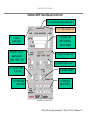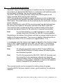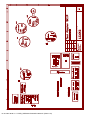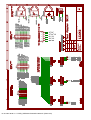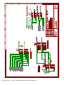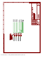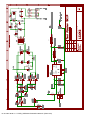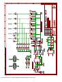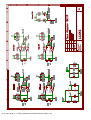
1
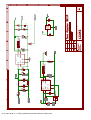
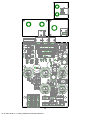
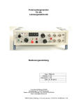
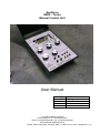
Semikron SKiiP - Tester Manual Control Unit Bild 1: Bedienungsanleitung User Manual type: version: document: date: L23005 1.2_eng 1.20 24.07.2013 Ing. Büro M.Billmann 07/2013 Lerchensteige 10 • D - 91448 Emskirchen Telefon +49-(0)9104-8235-88 • Fax +49-(0)9104-8235-89 email: [email protected] L23005_SKiiP-Tester_Bed_Anleitung_ENG_v1.20.doc; 24.07.2013; M.Billmann; 1/11 ING. BÜRO M.BILLMANN Semikron SKiiP Tester Manual Control Unit E: secondary side celvin measurement F: 41/2 digit voltmeter, ext G: primary side SKiiP interface, wired or optical A: 24VDC supply input B: SKiiP I / II / III supply select +24V; +15V; ±15V H: digital I/O status, LED I: pri analog signal monitor C: V CE up to 170V V F at 1.3A DC K: pri/sek monitor D: PWM signal generation L: PWM input signal matrix technical details may change without notice! L23005_SKiiP-Tester_Bed_Anleitung_ENG_v1.20.doc; 24.07.2013; M.Billmann; 2/11 Functional description Front side elements and connectors A: Supply input for auxiliary power supply 24VDC B: Selector for SKiiP supply C: Selector for VCE (IGBT) VF (Diode) measurement D: PWM signal generator, ≈ 10 kHz or permanent (CW) signal E: Interface for SKiiP secondary side power terminals F: Connector for external DVM G: primary side SKiiP interface GB/GH/GD, wired or optical H: Digital I/O status PWM SKiiP input signals I: Selector for monitoring analog primary side SKiiP signals K: Selector monitoring primary / secondary signal monitoring L: PWM signal matrix 2 PWM into 6 SKiiP inputs L23005_SKiiP-Tester_Bed_Anleitung_ENG_v1.20.doc; 24.07.2013; M.Billmann; 3/11 1 Contens page 2 About this document 2.1 How to use this document 2.2 Symbols and shortcuts 5 5 5 3 Description 3.1 Intended usage 3.2 Safety 3.3 Warnings, legal stuff 6 6 6 7 4 Functional description 8 5 Malefunction 9 6 Maintainance, service, add ons 6.1 Maintainance 6.2 Service 6.3 Add ons 7 Enclosure 7.1 Certificate 7.2 Schematic 7.3 Main PCB layout 9 9 9 9 10 11 A1-A14 B1-B2 L23005_SKiiP-Tester_Bed_Anleitung_ENG_v1.20.doc; 24.07.2013; M.Billmann; 4/11 2 About this document This manual describes - how the unit works - how to operate - how to handle mailfunction of SKiiP Tester L23005 2.1 How to use this document Read this manual carefully and complete to operate the L23005 correctly On pages 2 and 3 the elements and interfaces are listed and graphically shown for easy interpretation of the manual. This document is targeting at the following persons: - Professionals in power electronics - electronic engineers involved in Semikron SKiiP - developement 2.2 Used symbols and shortcuts note Notes will highlight advantages of certain operation modes to take maximum efficiency out of the unit. warning Warning notes: Read them carefully and follow these instructions. Warning notes shall prevent from danger and will help to prevent damage of the unit or the device under test. L23005_SKiiP-Tester_Bed_Anleitung_ENG_v1.20.doc; 24.07.2013; M.Billmann; 5/11 3 Description The SKiiP Tester L23005 is a manual operated, handheld unit designed for electrical implementation between a power supply, a digital voltmeter and a SKiiPPack to be tested. 3.1 Intended usage This unit is designed for commercial use inside electronic laboratories and in test areas for power electronic systems. It provides pulse patterns and commands for a rough functional test of SKiiP Power Modules. Do only operate the unit in dry areas. 3.2 Safety This part is written for Your safety. Please read this part carefully before operating the SKiiPTester L23005. Qualified personal The SKiiP Tester L23005 may only be used and operated by qualified personal. Qualified is who - has a suitable technical qualification and - has been trained by an operator or manufacturer in terms of operation and testing and - has access to this operating manual at any time. Legal notice Service or maintainance must only be carried out by qualified personal. Before starting any electrical or mechanical maintainance all energy sources must be disconnected. Spare parts and tools must meet the quality demands of the supplier. For warranty reasons do only use original spare parts. Technical details may change without notice. L23005_SKiiP-Tester_Bed_Anleitung_ENG_v1.20.doc; 24.07.2013; M.Billmann; 6/11 3.3 Warnings, legal stuff This unit generates pulse patterns that are suitable to test power electronic systems. It is always possible and – depending on the target of investigations – to exceed the limits of devices under test. Warning The SKiiP Tester L23005 is able to generate pulse patterns that may cause malefunction, degradation or damage of (high energy) systems which may lead to consequential damage of persons and / or asset values. Suitable personal security action must strictly be used! Testing SKiiPPacks with this tester must only be performed while SKiiPPacks are dismantled. Not any high energy system must be connected while testing! Any liability for damages caused by the use of this SKiiP Tester L23005 is excluded! Intended use: - Saving time while troubleshooting in applications - Decision assistant for „SKiiP is definitely faulty“ or „probably well“ - Test cycle time < 5min including test setup time - no dismounting of SKiiP into subcomponents - less unsubstantiated rejects to Semikron What is NOT covered? - NO 100% substitute for inhouse Semikron functional test - NO breakdown voltage measurement (only 170Vmax) - NO gate leakage current measurement - NO Rth-measurement, - NO measurement with rated current (only 1,3A DC,max) , ... L23005_SKiiP-Tester_Bed_Anleitung_ENG_v1.20.doc; 24.07.2013; M.Billmann; 7/11 4 Functional description The SKiiP Tester L23005 designed as a handheld test box that provides a test platform for dismantled SKiiPPacks in combination with additional parts as one digital multimeter, and auxiliary power supply. The SKiiP Tester L23005 generates configurable PWM signals for all today´s existing SKiiP primary side interfaces. SKiiP internal generated feedback signals (analogue as well as digital) can be monitored by using selector switches located on the front panels of the SKiiP tester. The actual values can be monitored by the mentioned, external digital voltmeter. By use of the selector switch [K] the monitoring path can be switched from the primary side signals to the power terminals of the SKiiP under test. The metered value is measured by Kelvin contacts directly at the power terminals and passed forward to the voltmeter in separate sense paths. Hint For a proper display a 4 ½ digit multimeter in „auto range“ voltage mode from 199,99mV to 200,00V is recommended. Depending on the setup of the selector switches an energy-limited source is applied to the power terminals. This source is capable of providing either a voltage up to about 170V or currents up to approximately 1,3 A. In combination with the chosen input signal configuration the forward voltage drop of IGBT / diode (manually force IGBT into ON state, or the blocking voltage of an IGBT / diode pair can be monitored in the range mentioned above. Hint All voltages generated inside the SKiiP Tester L23005 are energy limited. Because of safety reasons all affecting parts are redundant layouted. Hint The RJ-45 connectors for SKiiP-DC, SKiiP-AC terminals and the connection to the monitoring voltmeter are designed interconvertable. Every RJ-45 plug has all necessary signals available in a fixed pattern. Selection is done on the adaption boards. Standard RJ-45 cables are used. The received results can be compared to existing values for proper operating SKiiPs that were tested in known „good conditions“ as reference samples. L23005_SKiiP-Tester_Bed_Anleitung_ENG_v1.20.doc; 24.07.2013; M.Billmann; 8/11 5 Failure In case of failure immediately disconnect and power down the SKiiP Tester L23005. In case of damages please consult us directly. 7 Maintenance, Service, Accessories 7.1 Maintenance This unit does not need maintenance. It may only be operated in dry, clean areas. Take care that the unit is kept in a non dusty condition. Dust may cause dysfunction or reduced performance. Abandonment 1. Turn the unit OFF 2. Disable all energy sources and disconnect from mains and supply. Disassembly For disassembly proceed as followes: 1. Dismount the unit into single components. 2. Sort these components for material plus disposal criteria and hand it to an official waste management. Disposal Hint 7.2 Respect the specific disposal regulations of Your country. Service Never carry out repair on Your own, please contact: Ing.-Büro M.Billmann Lerchensteige 10 D-91448 Emskirchen phone: +49-(0)9104-8235-88 fax: +49-(0)9104-8235-89 email: M.Billmann@ ib-billmann.de L23005_SKiiP-Tester_Bed_Anleitung_ENG_v1.20.doc; 24.07.2013; M.Billmann; 9/11 7 Annex This section provides additional documentation that were given by Ing.-Büro M.Billmann or third parties: 7.1 Declaration of Conformity 7.2 Schematic of SKiiP Tester L23005 7.3 Part location on main PCB L23005_SKiiP-Tester_Bed_Anleitung_ENG_v1.20.doc; 19.05.2004; M.Billmann; 10/11 Dipl. Ing. Markus Billmann Lerchensteige 10 91448 Emskirchen Tel.: 09104 / 8235-88 0171 / 9987802 Fax : 09104 / 8235-89 email: [email protected] Dipl. Ing. M. Billmann · Lerchensteige 10 · 91448 Emskirchen Declaration of Conformity Manufacturers name and adress Ing.-Büro Markus Billmann Lerchensteige 10 91448 Emskirchen The Ing. Büro M.Billmann herewith declares conformity of the unit Semikron SKiiP Tester L23005 Due to the realization of and the design this unit meets the harmonized safety and health requirements in terms of EG – Maschinenrichtlinie 89/392 with changes 91/263EWG, 92/31 EWG, 93/68EWG This unit is intended for insertion in a test bench platform together with other parts. Operating our unit is forbidden as long as the certification for the complete test ambient system is not validated. Harmonized standards applied: EN60664 (VDE 0110) Isolation Pollution degree: 1 EN61010-1 (VDE 411-1) Safety instructions for electronic laboratory devices Technical documentation is fully provided. Operators manual is attached. Additional – Declaration: To prevent danger in terms of Maschinen - Richtlinie follow these instructions: 1.) Operate as described in the manual, only 2.) The unit is designed for Schutzklasse IP00 , because the devices to be tested are designed for Schutzklasse IP00. 3.) All dangerous voltages that are generated inside the unit are current and energy limited. The design is fail safe redundant even if one component (e.g. current limiting resistor) fails. Emskirchen, den 28.05.04 M.Billmann (C E O) L23005_SKiiP-Tester_Bed_Anleitung_ENG_v1.20.doc; 19.05.2004; M.Billmann; 11/11 13.10.2004 09:58:10 H:\SKD_SKiiPtester\L23005\L23005.sch (Sheet: 1/8) 13.10.2004 09:58:10 H:\SKD_SKiiPtester\L23005\L23005.sch (Sheet: 2/8) 13.10.2004 09:58:10 H:\SKD_SKiiPtester\L23005\L23005.sch (Sheet: 3/8) 13.10.2004 09:58:10 H:\SKD_SKiiPtester\L23005\L23005.sch (Sheet: 4/8) 13.10.2004 09:58:10 H:\SKD_SKiiPtester\L23005\L23005.sch (Sheet: 5/8) 13.10.2004 09:58:10 H:\SKD_SKiiPtester\L23005\L23005.sch (Sheet: 6/8) 13.10.2004 09:58:10 H:\SKD_SKiiPtester\L23005\L23005.sch (Sheet: 7/8) 13.10.2004 09:58:10 H:\SKD_SKiiPtester\L23005\L23005.sch (Sheet: 8/8) 13.10.2004 09:59:35 H:\SKD_SKiiPtester\L23005\L23005.brd