1
FLIDAS - Flight Data Studio
User Manual
Data Bus Tools GmbH
Rosenheimer Landstrasse 139
85521 Riemerling
Germany
Tel:
+49 89 62 70 79 61
Fax:
+49 89 88 90 95 15
Email:
Support-email:
Website:
www.databustools.de
FLIDAS User Manual 2.10.1
Data Bus Tools
Table of contents
1
FLIDAS Overview ............................................................................................................. 8
1.1
Outlook ....................................................................................................................... 8
1.2
How to use this manual .............................................................................................. 8
1.3
System requirements .................................................................................................. 8
1.4
Limitations / features out of scope ............................................................................. 9
1.4.1
1.5
2
Versions ...................................................................................................................... 9
Getting started .................................................................................................................. 13
2.1
Installing FLIDAS .................................................................................................... 13
2.2
Basic tutorial ............................................................................................................ 13
2.3
Parameter tutorial ..................................................................................................... 17
2.3.1
Creating an ICD ................................................................................................. 18
2.3.2
Creating an ICD Mapping .................................................................................. 19
2.3.3
Create Parameter Sets ......................................................................................... 20
2.4
3
Supported IRIG 106 specification version ........................................................... 9
Features by application area ..................................................................................... 22
2.4.1
Features for CH10 debugging ............................................................................ 22
2.4.2
Protocol level analysis ........................................................................................ 22
2.4.3
Parameter level analysis ..................................................................................... 23
2.4.4
Data presentation ................................................................................................ 23
2.4.5
Test data generation ........................................................................................... 23
Concepts ........................................................................................................................... 25
3.1
CH10 Files................................................................................................................ 25
3.2
Packets ...................................................................................................................... 26
3.3
Packet Entries ........................................................................................................... 26
3.4
Channels and Subchannels ....................................................................................... 26
3.5
CH10 Data Types ..................................................................................................... 27
3.6
TMATS attributes .................................................................................................... 27
3.7
Recording Events ..................................................................................................... 27
3.8
Time markers............................................................................................................ 28
3.9
Exporters .................................................................................................................. 28
3.10
Packet Entry Viewers ............................................................................................... 29
3.11
Protocol Viewers ...................................................................................................... 29
3.12
CH10 Data Type Filters ........................................................................................... 29
3.13
Preferences ............................................................................................................... 29
3.14
Properties .................................................................................................................. 30
3.15
Views ........................................................................................................................ 30
3.16
Error logging ............................................................................................................ 30
2 / 145
FLIDAS User Manual 2.10.1
Data Bus Tools
3.17
ICDs ......................................................................................................................... 31
3.18
Parameters ................................................................................................................ 31
3.19
Parameter Sets .......................................................................................................... 32
3.20
ICD Mapping............................................................................................................ 32
3.21
Parameter Viewers ................................................................................................... 33
3.22
Parameter sampling .................................................................................................. 33
3.22.1 Sampling modes ................................................................................................. 33
3.22.2 Initialization values ............................................................................................ 37
4
Reference .......................................................................................................................... 39
4.1
Help system .............................................................................................................. 39
4.2
Views ........................................................................................................................ 39
4.2.1
FLIDAS Repository View .................................................................................. 39
4.2.2
Packet View........................................................................................................ 40
4.2.3
Packet Entry View .............................................................................................. 42
4.2.4
Channel view ...................................................................................................... 43
4.2.5
TMATS View ..................................................................................................... 44
4.2.6
Recording event definition view ........................................................................ 45
4.2.7
Hex Packet view ................................................................................................. 45
4.2.7.1
4.2.8
Data manipulation ....................................................................................... 47
Parameter plug-in control View ......................................................................... 48
4.2.8.1
ICD Mapping Management ........................................................................ 48
4.2.8.2
Parameter Set Management ........................................................................ 49
4.2.9
ICD Mapping View ............................................................................................ 49
4.2.9.1
Channel / Subchannel ICD Mapping .......................................................... 50
4.2.9.2
Associated Parameter Sets .......................................................................... 51
4.2.10 Parameter Set View ............................................................................................ 51
4.3
Packet Entry Viewers ............................................................................................... 53
4.3.1
Analog Packet Entry Viewer .............................................................................. 53
4.3.2
PCM Packet Entry Viewer ................................................................................. 54
4.4
Preferences ............................................................................................................... 55
4.4.1
General Preferences ............................................................................................ 55
4.4.2
CH10 Data Type Filter Preferences ................................................................... 56
4.4.3
Packet entry viewers Preferences ....................................................................... 57
4.4.4
Default directories and files ............................................................................... 58
4.4.5
User map Preferences ......................................................................................... 59
4.5
Properties .................................................................................................................. 60
4.5.1
General File Information properties ................................................................... 60
4.5.2
General TMATS attributes properties ................................................................ 61
3 / 145
FLIDAS User Manual 2.10.1
Data Bus Tools
4.5.3
CH10 Data Type Filter properties ...................................................................... 62
4.5.4
General Channel and Subchannel properties ..................................................... 62
4.5.5
General Packet properties................................................................................... 63
4.6
CH10 Data Type support .......................................................................................... 65
4.6.1
ARINC 429 ........................................................................................................ 65
4.6.2
MIL 1553 ............................................................................................................ 66
4.6.3
Ethernet .............................................................................................................. 66
4.6.4
ARINC 664 (AFDX) / UDP payload ................................................................. 67
4.6.5
Video .................................................................................................................. 67
4.6.6
UART ................................................................................................................. 68
4.6.7
Analog ................................................................................................................ 69
4.6.8
Discrete............................................................................................................... 70
4.6.9
PCM ................................................................................................................... 70
4.6.10 CAN Bus ............................................................................................................ 72
4.6.10.1
DATaRec4 CAN bus support ..................................................................... 72
4.6.11 Time ................................................................................................................... 72
4.6.12 TMATS .............................................................................................................. 73
4.6.13 Recording events ................................................................................................ 73
4.6.14 Recording indices ............................................................................................... 74
4.6.15 Partly supported CH10 Data Types .................................................................... 74
4.6.15.1
Image data ................................................................................................... 74
4.6.15.2
Still Imagery................................................................................................ 74
4.6.15.3
Dynamic Imagery........................................................................................ 75
4.6.15.4
IEEE 1394 Physical Layer .......................................................................... 75
4.6.15.5
IEEE 1394 Transaction ............................................................................... 75
4.6.15.6
Message data ............................................................................................... 75
4.6.15.7
Mil 1553 16PP194 ...................................................................................... 75
4.6.15.8
Parallel ........................................................................................................ 75
4.6.15.9
TSPI / CTS (GPS NMEA-RTCM) ............................................................. 76
4.6.15.10 TSPI / CTS (EAG ACMI) ......................................................................... 76
4.6.15.11 TSPI / CTS (ACTTS) ................................................................................ 76
4.6.15.12 Fibre Channel ............................................................................................ 76
4.6.15.13 MJPEG....................................................................................................... 76
4.6.15.14 MJPEG 2000.............................................................................................. 76
4.7
Exporters .................................................................................................................. 77
4.7.1
Exporter Channel selection ................................................................................ 77
4.7.2
Exporter Subchannel selection ........................................................................... 78
4.7.3
Exporter target file selection .............................................................................. 79
4 / 145
FLIDAS User Manual 2.10.1
Data Bus Tools
4.7.4
Exporter target directory selection ..................................................................... 79
4.7.5
Time slice selection ............................................................................................ 79
4.7.6
CH10 File selection ............................................................................................ 81
4.7.7
Sampling mode selection ................................................................................... 81
4.7.8
Exporter types .................................................................................................... 81
4.7.8.1
Filtered CH10 .............................................................................................. 81
4.7.8.2
Replace TMATS in CH10 .......................................................................... 82
4.7.8.3
MPEG Video to MPEG file ........................................................................ 82
4.7.8.4
Play Audio from Analog ............................................................................. 82
4.7.8.5
MPEG TS replay (UDP streaming) ............................................................ 83
4.7.8.6
Analog to WAV .......................................................................................... 83
4.7.8.7
Analog to MAT format 4 (MATLAB) ........................................................ 84
4.7.8.8
Ethernet to PCAP ........................................................................................ 84
4.7.8.8.1 PCM throughput payload........................................................................ 85
4.7.8.9
Payload to file ............................................................................................. 85
4.7.8.10
General CSV exporting ............................................................................... 85
4.7.8.10.1 ARINC 429 to CSV .............................................................................. 86
4.7.8.10.2 MIL 1553 to CSV ................................................................................. 86
4.7.8.10.3 PCM to CSV ......................................................................................... 88
4.7.8.10.4 CAN bus to CSV .................................................................................. 88
4.7.8.10.5 Analog to CSV...................................................................................... 89
4.7.8.10.6 NMEA 0183 to CSV............................................................................. 90
4.7.8.10.7 Sampled Parameters to CSV................................................................. 90
4.7.8.10.8 ARINC 429 message based Parameters to CSV .................................. 91
4.7.8.11
TMATS to text file...................................................................................... 91
4.7.8.12
Further exporters ......................................................................................... 91
4.7.8.13
Sampled Parameters to MAT ...................................................................... 91
4.7.8.13.1 Exporting to multiple MAT files .......................................................... 92
4.8
Protocol Viewers ...................................................................................................... 92
4.8.1
Communication summaries ................................................................................ 92
4.8.1.1
Messages page ............................................................................................ 93
4.8.1.2
Processing info page ................................................................................... 94
4.8.1.3
Other pages ................................................................................................. 94
4.8.1.4
ARINC 429 communication summary ....................................................... 94
4.8.1.5
Ethernet communication summary ............................................................. 96
4.8.1.6
Mil 1553 communication summary ............................................................ 97
4.8.1.7
UART communication summary .............................................................. 100
4.8.1.8
MPEG transport stream summary ............................................................. 101
5 / 145
FLIDAS User Manual 2.10.1
4.8.1.9
Data Bus Tools
CAN bus communication summary .......................................................... 101
4.8.2
NMEA 0183 Protocol Viewer .......................................................................... 102
4.8.3
Navigation data view ........................................................................................ 103
4.9
4.8.3.1
The sequence of navigation data ............................................................... 104
4.8.3.2
The map .................................................................................................... 105
4.8.3.3
Instrument panel ........................................................................................ 105
4.8.3.4
Control panel ............................................................................................. 106
4.8.3.5
Details about the map ................................................................................ 106
Parameter Viewers ................................................................................................. 107
4.9.1
Parameter table Viewer .................................................................................... 107
4.9.2
Parameter graph Viewer ................................................................................... 108
4.10
4.9.2.1
Stripes ....................................................................................................... 108
4.9.2.2
Time information ...................................................................................... 108
4.9.2.3
The cursor ................................................................................................. 109
4.9.2.4
Zoom ......................................................................................................... 109
4.9.2.5
Time Markers ............................................................................................ 109
4.9.2.6
Performance .............................................................................................. 109
ICD formats ............................................................................................................ 109
4.10.1 CSV ICD formats ............................................................................................. 110
4.10.1.1
ARINC 429 simple CSV ........................................................................... 112
4.10.1.2
MIL 1553 simple CSV .............................................................................. 114
4.10.1.3
PCM simple CSV ...................................................................................... 115
4.10.1.4
Analog simple CSV .................................................................................. 117
4.10.1.5
CAN bus simple CSV ............................................................................... 118
4.10.2 NMEA 0183 on UART hardcoded ................................................................... 119
5
4.11
File loading options ................................................................................................ 120
4.12
Table exporting ...................................................................................................... 122
4.13
TMATS overriding ................................................................................................. 122
System administration topics ......................................................................................... 124
5.1
Portable installation ................................................................................................ 124
5.2
Backup .................................................................................................................... 124
5.3
Update .................................................................................................................... 124
6
Security........................................................................................................................... 126
7
FAQ ................................................................................................................................ 127
8
Open IRIG 106 issues .................................................................................................... 128
8.1
Storage of LSB first PCM data words in unpacked or packed PCM mode ........... 128
8.2
Storage of PCM data words in unpacked PCM mode with word sizes above 16 bits
128
6 / 145
FLIDAS User Manual 2.10.1
8.3
Data Bus Tools
Disabled analog Subchannels ................................................................................. 128
9
Feedback ......................................................................................................................... 130
10
What's new ..................................................................................................................... 131
FLIDAS 2.10.1 ....................................................................................................... 131
10.2
FLIDAS 2.10 .......................................................................................................... 131
10.3
FLIDAS 2.9 ............................................................................................................ 132
10.4
FLIDAS 2.8 ............................................................................................................ 132
10.5
FLIDAS 2.7.1 ......................................................................................................... 133
10.6
FLIDAS 2.7 ............................................................................................................ 133
10.7
FLIDAS 2.6.1 ......................................................................................................... 134
10.8
FLIDAS 2.6 ............................................................................................................ 134
10.9
FLIDAS 2.5 ............................................................................................................ 134
10.10
FLIDAS 2.4.1 ....................................................................................................... 135
10.11
FLIDAS 2.4 .......................................................................................................... 135
10.12
FLIDAS 2.3 .......................................................................................................... 136
10.13
FLIDAS 2.2 .......................................................................................................... 137
10.14
FLIDAS 2.1.1 ....................................................................................................... 137
10.15
FLIDAS 2.1.0 ....................................................................................................... 138
10.16
FLIDAS 2.0.0 ....................................................................................................... 138
11
10.1
Legal ............................................................................................................................... 140
11.1
Free license ............................................................................................................. 140
11.1.1 Third Party Software ........................................................................................ 140
11.1.1.1
11.2
Eclipse Application framework ................................................................ 140
FLIDAS end user license agreement (EULA) ....................................................... 140
11.2.1
License grants ................................................................................................... 140
11.2.2 Warranty ........................................................................................................... 140
11.2.3 Applicable law and place of jurisdiction .......................................................... 141
11.2.4 Changes to contract .......................................................................................... 141
11.2.5 Third Party Software ........................................................................................ 141
11.2.5.1
11.3
Eclipse Application framework ................................................................ 141
Third Party: Eclipse Public License - v 1.0 ............................................................ 141
7 / 145
FLIDAS User Manual 2.10.1
Data Bus Tools
1 FLIDAS Overview
FLIDAS reads IRIG 106 Chapter 10 files with flight data and allows accessing the data on the
raw data, protocol and Parameter level for display and export. It also allows debugging the
CH10 file structure itself. There are three versions:
A free version (limited raw data, protocol and CH10 level)
A basic commercial version (raw data, protocol and CH10 level)
A Parameter plug-in as add-on to the basic commercial version (Parameter level)
Currently there is no explicit support for recordings of distributed multiplexer systems or
TMATS configuration changes during a single recording.
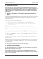
1.1 Outlook
Besides continuous improvements there are several areas where extensions are planned:
Support for more CH10 Data Types on Parameter level
Soft real time replay of data to the GUI
Java API for CH10 File access and GUI integration
Several things are considered out of scope even for the future:
Display of live data (i.e. not coming from a file)
Hard real time replay of data to the GUI or physical lines
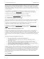
1.2 How to use this manual
This manual consists of several sections:
The Overview chapter contains some initial information you should read before
starting.
The Getting started chapter contains tutorials for the basic use of the program but
does not explain all functionality.
The Concepts chapter explains general terms and ideas but not the use of these
concepts. Instead it links you to the graphical user interface elements that work with
these concepts.
The Reference chapter then covers all the user interactions with the tool in detail.
Further chapters cover topics that did not fit in somewhere else or are not directly
related to the use of the tool.
The Legal chapter in the end explains the conditions under which you may use the
tool. If you don't agree you may not use it.
The manual offers a lot of cross linking between topics that you could use to find additional
information.
1.3 System requirements
8 / 145
FLIDAS User Manual 2.10.1
Data Bus Tools
Most of FLIDAS is written platform independent. Only the GUI aspects are linked to specific
operating systems. FLIDAS is officially available for Windows XP or higher. Versions for
other operating systems (Linux, Solaris, Mac OS ...) can easily be provided on request (most
of the time free of charge). You may use the free version to see if the GUI aspects work out in
your environment.
To run FLIDAS a Java installation of at least Java 7 is needed. It is free and you can
download it for example from www.java.com but most computers have it preinstalled.
FLIDAS can arrange windows over multiple monitors if available.
It is possible to create portable installations that run from an USB stick.
1.4 Limitations / features out of scope
This section shall clarify some topics that are out of scope of FLIDAS or that are limitations
that might be relevant to you. Some of these topics may be addressed in future versions:
FLIDAS is not downloading the CH10 Files from the recorder. Files must be accessible
within the environment of the computer where FLIDAS is installed.
FLIDAS does not support all CH10 Data Types in detail. Look up the CH10 Data Type
support section for the level of support for each CH10 Data Type.
1.4.1 Supported IRIG 106 specification version
FLIDAS offers support for the CH10 File format version up to the 2015 version with one
exception: Video format 0 packets from 2004 are not supported. (The only sample data
available to us doesn't comply with the standard, so it was not safe to implement. However the
actual video data was properly available so you might try exporting video data on your own
risk)
The support in general is implemented in this way:
The support for the 2015 version has been implemented
All supported CH10 Data Types have been checked for differences between
specification versions
Files of older versions will still show the data according to the 2015 version.
Since all unused data bits in older standards are required to be set to 0, options not
available in that specification will use the "0-value option"
The "0-value option" has been checked to be a useful default also for older versions.
In rare situations there is a special treatment for older versions.
Example: Assume a packet was defined to be in little endian coding in the 2004 standard. The
2005 standard added the option to have little or big endian coding but little endian is coded as
a 0. Since the coding bit was not used in 2004, it is set to 0 by default. The GUI will show a
little endian property also for the 2004 standard although it is not coded as an option in the
data file but defined by the specification instead. The fact that it is little endian coded is
however still correct.
1.5 Versions
9 / 145
FLIDAS User Manual 2.10.1
Data Bus Tools
FLIDAS is available as a free version which displays the data and provides a few full
functional export features for demonstration. There is also a commercial basic version with
more exporting options and better accessible data interpretations at a very affordable price.
Since many parts of the IRIG 106 standard are open to interpretation and may be handled
differently by recorder manufacturers, you are invited to try your IRIG 106 Chapter 10 files
with the free version first.
An additional commercial Parameter plug-in adds support for conversion of raw data to
engineering units. This plug-in requires the commercial basic version as a base.
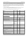
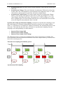
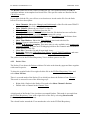
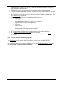
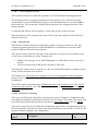
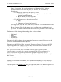
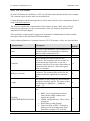
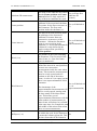
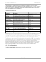
Here is a summary of the differences between the general versions:
Feature
Free Version
Basic
Version
Basic Version with
Parameter plug-in
Read IRIG 106 chapter 10 file up to IRIG
106-15
X
X
X
Display the list of Packets
X
X
X
Support for Recording Events
X
X
X
X (data
Display the Packet Entries within Packets of displayed in
supported CH10 Data Types
simple lines
of text)
X (same data displayed but split
to individual and configurable
columns. For some CH10 Data
Types more data available)
Display the available Channels and
Subchannels with some TMATS attributes
X
X
X
Display the TMATS setup
X
X
X
Debugging of corrupted files (missing
Packets, checksum errors etc.)
X
X
X
Locating Packet and Packet Entry errors
- (Errors are
shown but no
aid to
X
navigate to
them)
X
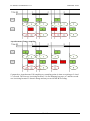
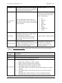
Display of all common Packet Properties and
structured hex display of whole Packet data
X
X
Modification of Packet data within hex
display
-
X
X
Play audio from Analog subchannel
X
X
X
Video preview of MPEG transport stream
-
X
X
Display graph of analog subchannels within
sequence of Packets
X
X
Display PCM minor frames within sequence
of Packets
X
X
Display UART subchannel or UDP packets
as NMEA 0183
-
X
X
Display and replay of NMEA 0183
-
-
X
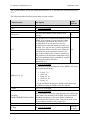
10 / 145
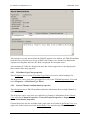
FLIDAS User Manual 2.10.1
Data Bus Tools
Parameters (from UART subchannel or UDP
packets) on build-in or user defined map and
instruments.
More detailed world map for NMEA 0183
map display
-
-
available on request
without additional
cost
Tabular display of sampled Parameters
-
-
X
Graph display of sampled Parameters
-
-
X
Unicode UTF-8 support for Japanese,
Chinese, Cyrillic etc. letters
X
X
X
Override settings of CH10 files with external
X
TMATS file
X
X
Support for CAN buses in DATaRec4
(Zodiac Data Systems format)
-
available as separate plug-in
MPEG Video to MPEG file
X
X
X
TMATS to text file
X
X
X
CH10 to filtered CH10 file (filtering time
and channels. The result is no formally
correct CH10 file (see manual))
X
X
X
Ethernet to PCAP
-
X
X
MIL 1553 to CSV
-
X
X
ARINC 429 to CSV
-
X
X
CAN bus to CSV
-
X
X
PCM minor frames to CSV
-
X
X
PCM throughput mode stream to binary file -
X
X
Analog subchannel(s) to WAV, CSV or
MAT format 4 (MATLAB)
-
X
X
UART subchannel or UDP packets as
NMEA 0183 to CSV
-
X
X
UART subchannel or UDP packet payload to
file
Examples are streamed video to MPEG or
NMEA 0183 to text
X
X
MIL 1553 / ARINC 429 to Airbus Defence
& Space real time test system AIDASS 2000
(also MaTE, SYGAM) TRF format (can be
used for replay or analysis in AIDASS)
(AIDASS is a registered trademark of
Cassidian Germany)
available as separate plug-in
Export all important GUI tables to CSV
-
X
X
Sampled Parameters to CSV or MAT
(configurable period or asynchronously on
change)
-
-
X
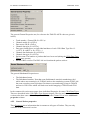
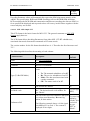
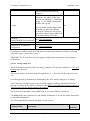
Exporters
11 / 145
FLIDAS User Manual 2.10.1
Data Bus Tools
ARINC 429 message based Export to CSV
using Parameters (no sampling but export at
time of occurrence. Export of protocol
information and one included Parameter)
-
X
Export CH10 file with modified TMATS
setup
X
X
-
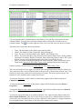
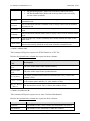
Communication summaries (message types, periods, error counts etc.)
MIL 1553
X
X
ARINC 429
-
X
X
CAN bus
-
X
X
UART
-
X
X
Ethernet (including payload analysis for IP4
and UDP)
X
X
Video MPEG Transport Stream
X
X
-
Parameter decoding management (engineering unit conversion)
Definition of engineering unit (EU)
conversions for Parameters in an external
ICD file (CSV text file. Can be used with
Excel).
-
-
X
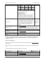
-
X
-
X
Parameter decoding support for:
ARINC 429
CAN bus
MIL 1553B (format 1)
PCM (See manual for details)
Analog
NMEA 0183 (e.g. GPS, Galileo,
GLONASS and Beidou GNSS) on
UART. Fixed ICD with most relevant
Parameters from RMC, GGA and
VTG sentences.
Other CH10 Data Types on request
or added with further releases.
Definition of Parameter Sets (group of
parameters used in the same test situation)
and joining of existing Parameter Sets.
-
The features of all versions will be continuously enhanced.
12 / 145
FLIDAS User Manual 2.10.1
Data Bus Tools
2 Getting started
2.1 Installing FLIDAS
Make sure you have received a version appropriate to your operating system. 32 and 64 bit
versions relate to your installed Java version, not to your operating system.
To install simply extract the ZIP archive in a directory on your computer. There is no
installation required.
Notes:
If you are concerned if the download went OK check the FAQ section for the
checksum verification process.
All configuration data of FLIDAS will be stored in this directory so you should make
sure this directory is accessible for writing (not only during installation). This might
not be the case for the "Program Files" directory on newer Windows releases.
The Windows native ZIP archive support is said to have problems with long file
names. If you encounter problems, use a third party tool (e.g. 7-zip) for extracting the
archive.
There are two warnings for Eclipse based applications which probably also apply to
FLIDAS and should be followed:
o Avoid path names longer than 255 characters on Windows
o Do not use spaces in the path
FLIDAS is based on the Eclipse platform. It is possible to integrate it in one of the many
Eclipse platforms available. There are also specialized Eclipse platforms for the aerospace
industry. If you are interested, contact us.
When Java is properly installed, you should be able to start the FLIDAS executable in the
directory where you extracted the ZIP archive.
Notice: You can also create a portable installation on an USB stick without the need of a local
Java installation. Here are the procedures.
2.2 Basic tutorial
This tutorial will show you how to do the first steps in FLIDAS. It will show you how to
inspect a file's content. On the way it will teach you some basic concepts of the user interface
and link you to further topics somewhere else in the documentation.
Start FLIDAS with the FLIDAS executable in your installation directory.
To open a CH10 File click File > Open CH10 File... or use the keyboard shortcut Alt+O.
If you don't have a file and still want to test out FLIDAS, you could download sample files
from the third party website www.irig106.org.
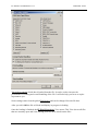
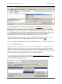
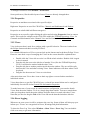
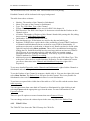
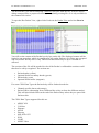
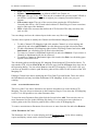
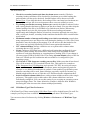
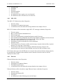
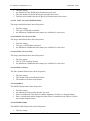
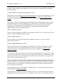
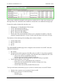
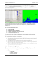
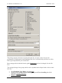
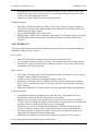
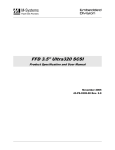
After you have selected the file, the File Loading Options dialog pops up:
13 / 145
FLIDAS User Manual 2.10.1
Data Bus Tools
This dialog controls which data is loaded from the file. It can be used to increase the
performance of loading and overall handling of the file. It will also help you focus on topics
important to you.
Some settings come from the global Preferences and can be changed for each file here.
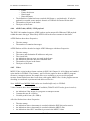
After you click OK the file will load and display its progress in loading.
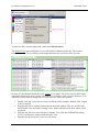
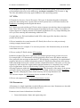
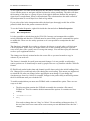
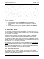
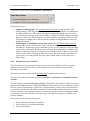
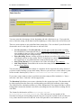
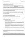
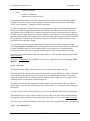
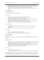
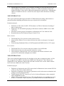
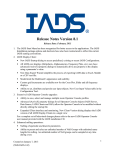
Once the loading is finished, the FLIDAS Repository View opens. This View shows all files
that are currently open and is the starting point for most actions on the files.
14 / 145
FLIDAS User Manual 2.10.1
Data Bus Tools
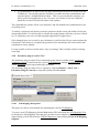
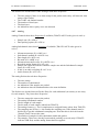
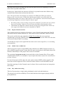
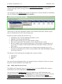
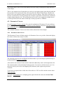
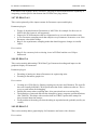
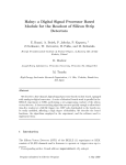
To show the file's content right-click it and select Show Packets.
The Packet View opens and shows a list of all Packets contained in the file. The colored
border around the View will help you distinguish between several open files at a time.
By now you should have heard the word "View" a few times. The term is used in the Eclipse
application framework (that is used by FLIDAS) for a Window with a specific behavior. You
will need to know how to arrange the Views so here are some basic actions:
Double-click the Views title to resize it to fill the whole window. Double-click it again
to size it normal
Drag the title bar to another position inside the main window. The area will be split
between this View and other existing Views. Some indicators will show where it will
be placed
Drag the title bar next to the title bar of another View (like the FLIDAS Repository
View). It will then be stacked with the other View.
Drag the line between two Views to resize them
15 / 145
FLIDAS User Manual 2.10.1
Data Bus Tools
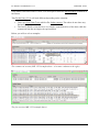
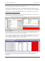
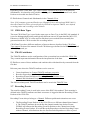
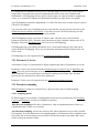
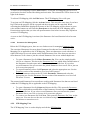
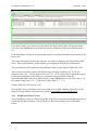
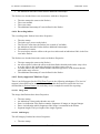
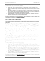
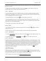
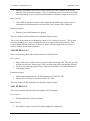
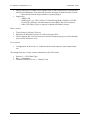
Now double-click on a Packet. A new View will open to show the Packet Entries contained in
the Packet
This Packet Entry View will look different depending on the situation:
There are CH10 Data Types which offer further support. The others do not show any
Packet Entries.
The free FLIDAS version shows a very simple, unstructured list of the data, while the
commercial one has an improved representation
Below you will see a few examples:
The commercial version (MIL 1553 example above - a lot more columns to the right)
The free version (MIL 1553 example above)
16 / 145
FLIDAS User Manual 2.10.1
Data Bus Tools
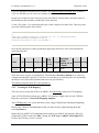
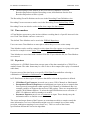
The commercial version (Analog example above)
Now arrange the Packet View and the Packet Entry View side by side (e.g. drag the Packet
Entry Views tab to the lower part of the screen).
Click on the "Link with selection" icon on the top of the Packet Entry View. Then click on
a new Packet in the Packet View. See how the Packet Entry View changes to show the new
Packet's content. This link between the selected Packet and the displayed Packet Entries can
be enabled or disabled as you have just done. The View will freeze on the shown Packet
Entries or will stay synchronized with the latest selection in the Packet View of the same
color (i.e. belonging to the same file).
Now click on a new Packet in the Packet View and then hit the F1 key (or whatever key is
associated with help on your system). Online help will open explaining the Packet View. You
can use this on many other areas of the application too.
This tutorial ends here. There are a lot of other features to try out guided by the manual. Some
major areas where you might want to start are:
Inspecting the Channels
Communication summaries
Exporting Data
Parameter decoding
A good thing to do is also to right-click on items inside the tables in the Views that you use in
order to bring up the context menu. This shows you available actions in many places that you
can then read about in the context sensitive help for the View.
2.3 Parameter tutorial
This tutorial will show you how to work with Parameters i.e. how to set up your system to
decode raw data to an engineering unit level. The tutorial expects that you are familiar with
the basic use of FLIDAS as explained for example in the basic tutorial.
All features described here rely on the commercial Parameter version.
17 / 145
FLIDAS User Manual 2.10.1
Data Bus Tools
The tutorial will use ARINC 429 as an example but you should be able to apply this to other
CH10 Data Types too.
FLIDAS offers several functions that use Parameters for displaying (Parameter Viewers) and
exporting (Exporters). Before these functions can be used you must teach the system about the
Parameters that are circulating on the data buses of your avionics system.
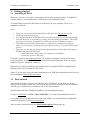
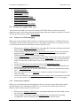
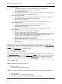
Setting up your system consists of several steps:
1. You must manually define ICDs. These are files that describe which data is present on
a single specific data bus and how it is decoded to engineering units. Note that it is
also possible to order support for your already existing company internal file format.
2. You must tell FLIDAS which Channels and Subchannels of your CH10 Files are using
which ICD. We call this an ICD Mapping.
3. You must create Parameter Sets to define a selection of Parameters you intend to use
e.g. for displaying. You can store and join these Parameter Sets or just use them as a
one-time selection.
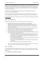
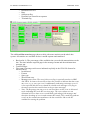
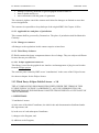
These three things you need to create can be seen in the green box in the picture below. This
set up is intended to be used over a broader scope of CH10 Files so ideally this is a one-time
set up action. Of course your avionics system may change as well as your CH10 Channel
setup. Some mechanisms are implemented to limit the changes required to adapt to this.
2.3.1 Creating an ICD
18 / 145
FLIDAS User Manual 2.10.1
Data Bus Tools
ICDs are managed externally from FLIDAS. The default format for ARINC 429 would be a
CSV text file that you can create for example with Excel.
Ideally you would now start with one of your real ARINC 429 interfaces and enter some of
the Parameters that circulate periodically on the interface.
Create a file with a *.csv extension and open it with a simple text editor first. Then copy and
paste the following three lines inside:
V1
Name;Unit;Comment;Label[oct];SDI;MSB pos (31..0);Length;Encoding
(BNR/UBNR/BCD/Enum);Enumdef;Scaling
Pressure Altitude;ft;;203;;11;18;BNR;;1
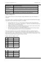
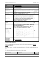
Save the file and open it with a spreadsheet application like Excel. The result should look
somewhat like this:
V1
Name
Encoding
MSB
(BNR /
Unit Comment Label[oct] SDI pos (0 Length
Enumdef Scaling
UBNR / BCD
based)
/ Enum)
Pressure
ft
Altitude
203
11
18
BNR
1
Now enter some of your own definitions. The Parameter Pressure Altitude is of course an
example and should be deleted. If you have no own data, you could keep the line and modify
the label to one of the label numbers that occur on your interface.
The detailed format of this file is described here.
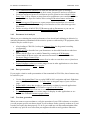
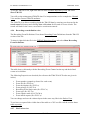
2.3.2 Creating an ICD Mapping
The next step is to map this ICD to an ARINC 429 Subchannel with your ICD Mapping.
Open a CH10 File that contains your ARINC 429 interface. Right-click it in the FLIDAS
Repository and select Create ICD Mapping template.
The ICD Mapping View opens and shows some empty Channel and Subchannel Mappings.
Remove the Channels and Subchannels that you don't need by right-clicking them and
selecting Remove.
Right-click the ARINC 429 Subchannel that contains you ARINC 429 interface that you
prepared the ICD for and select Edit. Change the ICD Type to ARINC 429 Simple CSV.
Choose the ICD file you have created.
19 / 145
FLIDAS User Manual 2.10.1
Data Bus Tools
Enter a Mapping ID for your ARINC 429 definition. This could be something like "Left
Engine". Whenever you store a selection of Parameters (Parameter Set) these will store the
Mapping ID and the Parameter name for each Parameter. Therefore if you have CH10 Files
where the same ARINC 429 interface is recorded on a different Subchannel, you can create a
new ICD Mapping for it but assign the same Mapping ID. In result you Parameter Sets can be
used with both ICD Mappings. So the Mapping ID prevents you from changing your
Parameter setup too often. The Mapping ID may be any text but not contain "#".
The ID field must contain the number of your ARINC 429 Subchannel as it appears in the
CH10 File. Some files use different numberings in TMATS (see also the FAQ).
Accept the changes with OK and also close the ICD Mapping View. Save when asked for it.
2.3.3 Create Parameter Sets
Finally you need to create a Parameter Set to define which Parameters you want to use for
display or exporting. These Parameter Sets may be stored for future use and also joined for
example to show "Engine operational parameters" and "Primary flight parameters". However
it is not required to save them. It is perfectly valid to create a Parameter Set just for a one-time
Parameter selection to show the data without saving the Parameter Set.
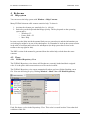
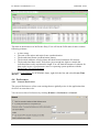
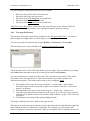
To create Parameter Sets you first need to open the Parameter Plug-in Control View. This
View controls most of the Parameter based actions. To open the View click Window > Show
View > Parameter Plug-in Controls.
20 / 145
FLIDAS User Manual 2.10.1
Data Bus Tools
Working with Parameter Sets requires an activated ICD Mapping since the Parameter Set only
knows the name but not the definition of the Parameters.
To activate the ICD Mapping, first select it by clicking the Select button and choosing the
ICD Mapping file you have saved in the last step. It is then activated by clicking at Activate.
Note that you can pre-select the ICD Mapping file for the next FLIDAS sessions using the
Default directories and files Preferences.
With the activated ICD Mapping you can now work with Parameter Sets. Create a new one
with the New button on the lower end of the View.
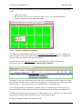
Expand the Mapping ID of your ARINC 429 Subchannel in the Available Parameters area
to the left and select a few Parameters with the checkboxes.
You can now use this Parameter Set to decode the ARINC 429 Subchannel to the GUI. Click
at View / Export > Parameter Viewers > View Parameter table on the lower end of the
View. Finish the dialog and wait for the results to appear.
This tutorial ends here. There are a lot of other features to try out guided by the manual. The
main points where to learn about the Parameter features are the concepts and View
descriptions:
21 / 145
FLIDAS User Manual 2.10.1
Data Bus Tools
Parameter concept
Parameter Set concept
ICD concept
ICD Mapping concept
Parameter sampling concept
Parameter Plug-in Control View
ICD Mapping View
Parameter Set View
Display of Parameters as graphs
2.4 Features by application area
This section cross links you to specific features of FLIDAS that are useful for specific
application areas. It does not point out general features that are needed everywhere. For some
of these general features read the basic tutorial.
2.4.1 Features for CH10 debugging
When you are developing CH10 recorders or software yourself, have to validate CH10 softor hardware deliveries from suppliers, have to deal with corrupted files or encounter errors in
your measurement chain, these features may be useful for you:
When you are loading a CH10 file you can enable the checksum checking and control
how FLIDAS handles massively corrupted files.
After loading a CH10 file, look up the general file information for an error summary
and look up the Channel View for the general recording configuration, detected
TMATS problems and Channel Packet counts.
Use the TMATS View to see the uninterpreted TMATS data and search in the content.
Look up a list of all corrupted Packets with the Packet View in the corrupted Packets
mode. You can also use the Packet View in its regular mode and jump from error to
error.
Look into Packets to see its decoded content in the Packet Entry View.
Look up the general Packet Properties to see all the Packet header information in raw
and interpreted form including error information.
Use the Hex Packet View to see the whole Packet's content in a structured hex editor
style.
Use some of the lower level Exporters to extract recorded raw data and compare it
with your input.
Create new CH10 files by filtering Channels and time slices to concentrate on the data
you are interested in, share it with others or send to Data Bus Tools for debugging.
2.4.2 Protocol level analysis
When you are looking into general problems with your avionics system like broken cables,
spurious parity errors, unresponsive LRUs etc. or you want to verify the protocol level
behavior, these features may be useful for you:
When you are loading a CH10 file you can suppress data types in the file that you are
not interested in.
After loading a CH10 file, look up the Channel View for the general recording
configuration, detected TMATS problems and Channel Packet counts.
22 / 145
FLIDAS User Manual 2.10.1
Data Bus Tools
Use Communication Summaries to look into the different types of messages
circulating on your avionics system, their counts, frequencies and error conditions.
Look into interpreted protocol level data at specific points in time with the Packet
Entry View. Use its features to jump from error condition to error condition within a
group of Packets. Specific features allow seeing PCM minor frames and analog
curves.
Use various types of Exporters to export protocol data and analyze it in external
applications. This includes exporting several interfaces of the same data type time
interleaved.
Define error bits of MIL-STD 1553B status words as Parameters so you can see
occurrences of these errors in the Parameter Table Viewer
2.4.3 Parameter level analysis
When you are evaluating the actual performance of an aircraft and validating its behavior by
analyzing Parameters transmitted on the avionics system or collected by FTI equipment, these
features may be useful for you:
After loading a CH10 file, look up the Channel View for the general recording
configuration.
Define an ICD to describe how your Parameters are decoded from the recorded raw
data.
Define which ICD to use on which Channel by creating an ICD Mapping.
Control which ICDs are active and start most Parameter based actions from the
Parameter Plugin Control View.
Organize your Parameters in Parameter Sets in order to reuse these sets or joined sets
for future exports and other actions.
Export Parameter values over a time range for use in other applications or view them
directly in FLIDAS as tables or graphs.
2.4.4 Data presentation
If you require visual or audio presentation of data contained in CH10 files, these features may
be useful for you:
Use the Navigation Data View to replay NMEA 0183 navigation and basic flight data
on a map and some instruments. Use user maps to integrate maps of your own test
range.
Export MPEG video data in order to immediately see them in external applications.
Replay audio data directly in FLIDAS or export it to WAV files.
See analog curve forms from one or several Packets.
Export Parameter values over a time range for display in other applications or see
them in the FLIDAS Parameter graph viewer.
2.4.5 Test data generation
When you want to create test data to verify the operation of your CH10 software or recorders,
you can prepare specific test data to check if your software works correctly on them or if your
recorder can replay the data properly. To do so you could use real files and manipulate them
to include very specific error cases that you might not be able to easily produce otherwise.
23 / 145
FLIDAS User Manual 2.10.1
Data Bus Tools
Use the Hex Packet View to modify positions inside a CH10 Packet and set error flags
or manipulate data.
24 / 145
FLIDAS User Manual 2.10.1
Data Bus Tools
3 Concepts
3.1 CH10 Files
In FLIDAS you are loading IRIG 106 Chapter 10 files in order to analyze them or export their
content. In short we will call them CH10 Files. Almost every aspect of the system depends on
a specific file that has been loaded.
When you are loading a file, the system will read some of its TMATS attributes and collect
some information about the contained Packets. This is always necessary before you can work
with the file. Some data may be skipped when reading, which depends on your configuration.
You can cancel the loading to show what data has been processed so far.
Once a file is loaded it will be visible in the FLIDAS Repository View from where you can
take actions on the file.
You can load several files at a time. Even the same file can be loaded several times with
different configuration. Each file will have an assigned color that will be reused in other
Views to allow you distinguishing between the different files the Views are based on.
When you close a file, all Views connected with it will be closed too.
Only limited data is collected when loading the file. So actions like inspecting a Packet's
content or exporting data from it will access the file again.
Even though a loaded file doesn't use up too many resources, you should consider closing it
when you don't need it anymore.
When the loading of a file encounters errors, FLIDAS gives you the choice to use the data
loaded so far. This allows working with corrupted files.
Loading a CH10 File may come to one of the following results:
OK: The file has properly loaded. Never the less it may contain errors but these have
been handled properly.
User abort: You have manually cancelled the loading.
Corrupted Packets: During the load a corrupted packet was encountered (i.e. invalid
Packet sync or Packet header checksum). Your current configuration tells FLIDAS to
stop loading under this condition. You can configure FLIDAS to search for the next
valid Packet and continue loading from there with the File loading options.
Unexpected error threshold: FLIDAS tries to handle most kinds of errors. There
may be errors that the development team did not anticipate they could be happening.
In this case FLIDAS logs these errors and continues processing the next Packet. After
reaching the maximum allowed number of these errors, FLIDAS gives up loading the
file. The maximum error number can be configured in the File loading options.
File error: There was an error accessing the CH10 File dealing with disk or network
(if remotely stored) access.
Unrecoverable error: FLIDAS encountered an error and tried to find the next valid
Packet within the file to continue processing from a safe position in the file. It was not
able to find such a safe position because of follow up errors.
25 / 145
FLIDAS User Manual 2.10.1
Data Bus Tools
3.2 Packets
When this manual refers to a Packet it refers to the IRIG 106 Chapter 10 definition of a
Packet. This means it is a collection of data retrieved from a Channel. Most of the time this is
data coming from another system where it has been monitored.
Packets may collect data of up to 100ms. FLIDAS expects that Packets from the same
Channel are stored in time sequence while Packets of different Channels may be out of order
in the file.
FLIDAS offers a Packet View to see a list of Packets with some Properties associated with it.
Most Packets decode into smaller units of data called Packet Entries. This would be the level
of a message for most CH10 Data Types.
FLIDAS calculates the time stamps of Packets relative to the Time Packets in the file. Details
can be seen in the Time section.
When loading Packets, FLIDAS will check the sequence numbers in the Packets. If within
one Channel a sequence number is missing, FLIDAS will insert a lost Packets marker into the
stream of Packets. This marker will show information on the number of missing Packets on
the Channel. The time stamp of the marker will be one timer tick of the 10 MHz relative time
counter before the Packet that revealed the missing sequence number and will indicate the
type of this Packet. This means that missing computer generated Packets (TMATS, User
Defined Data, Recording Indices / Events) may not indicate the correct type as all types of
computer generated Packets share the same sequence counter (if they are on Channel 0) and
therefore it is not possible to know which type is missing.
3.3 Packet Entries
Packet Entries is the common term used here for CH10 Data Type dependent data structures
that are contained in a Packet. This is the real data transmitted on a physical interface. For
Ethernet this is for example a frame, for MIL 1553 a message.
FLIDAS decodes Packets into Packet Entries only on request. Loading the file itself does not
decode it and this is done for example when the Packet content is viewed or the data is
exported.
FLIDAS offers Packet Entry Viewers to see the Packet Entries within one Packet. The Packet
Entry Viewers are individual for each type of CH10 Data Type in the commercial version.
3.4 Channels and Subchannels
The term Channel is used here in the same sense as in the IRIG 106 standard. It is therefore a
stream of data of the same CH10 Data Type. Some Channels can be subdivided in
Subchannels. For some CH10 Data Types IRIG 106 uses different terms for subchannels like
"Bus" on ARINC 429 and "Network" on Ethernet. We use the term Subchannel for all of
them here.
26 / 145
FLIDAS User Manual 2.10.1
Data Bus Tools
Depending on the CH10 Data Type, some Packets contain Packet Entries from different
Subchannels. It is therefore only possible to distinguish data on the Subchannel level, when
Packets are decoded into Packet Entries.
FLIDAS shows Channels and Subchannels in the Channels View.
Note: If all computer generated Packets use Channel ID 0 (as allowed until IRIG 106-11)
then this Channel 0 will be split artificially by FLIDAS to separate TMATS, user defined,
recording index and recording event Channels.
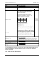
3.5 CH10 Data Types
The term CH10 Data Type is used in the same sense as Data Type in the IRIG 106 standard. It
is used to distinguish physically and logically different sources of input data like MIL 1553,
Ethernet or ARINC 429. It is also used on data that is not recorded from externally but
generated inside the CH10 recorder like recording indices.
CH10 Data Types have different attributes of interest that are described in the CH10 Data
Type support section of the manual. Not all CH10 data types defined in the IRIG 106 standard
are fully supported yet.
3.6 TMATS attributes
The TMATS attributes are the configuration of the system that has recorded the CH10 File.
They contain important information about the interpretation of the data.
FLIDAS uses some of these attributes and combines this with data directly extracted from the
file data.
Relevant parts where the TMATS attributes can be seen are:
General attributes in: General TMATS attributes properties
Recorder-Reproducer Attributes in: Channel View
Recording Events Definitions: Recording Event Definitions View
Channel and Subchannel Properties
The full but uninterpreted TMATS attributes can be seen in the TMATS View
3.7 Recording Events
The term Recording Events is used in the sense of the IRIG 106 standard. Their meaning is
defined in the TMATS attributes and their occurrence is logged within the Recording Events
Packets of the CH10 File.
Recording Events always belong to a Channel. Different problematic situations can occur:
The Recording Events Packets of the CH10 File use a different channel than channel
0. The TMATS attributes do not define the channel number but declare Events:
FLIDAS will allocate the Recording Event Definitions to the Channel used in the
Recording Events Packets. If several Recorder/Reproducers declare Recording Events
without Channel, all definitions after the first Recorder/Reproducer will be rejected.
27 / 145
FLIDAS User Manual 2.10.1
Data Bus Tools
The Recording Events Packets of the CH10 File use channel 0: If several
Recorder/Reproducers declare Recording events, all definitions after the first
Recorder/Reproducer will be rejected.
The Recording Event Definitions can be seen in the Recording Event Definition view.
Recording Event occurrences can be seen in the Recording Events Packet Entry Viewer.
Recording Events can also be used to define time ranges for data exports.
3.8 Time markers
A Time Marker represents a point in time within a recording that is of specific interest for the
user. Each Time Marker can have a note on it.
The defined Time Markers can be seen in the FLIDAS Repository.
Users can create Time Markers on most places where they see or use a time stamp.
Time Markers can be used for example to select time slices for exports or to jump to the point
in time for example in some Packet Views or the Parameter Graph Viewer.
Time Markers are associated with a loaded CH10 file. If you close the file, the Time Markers
are removed.
3.9 Exporters
An Exporter is a FLIDAS feature that converts parts of the data contained in a CH10 File to
another format. The other format may be a file or also a direct output (like replay of contained
audio data).
Exporters most of the time focus on a specific CH10 Data Type and allow selecting a
combination of Channels or Subchannels and a time slice.
In FLIDAS there are three types of Exporters that differ on how the input data is defined:
CH10 Data Type Exporters just need one or more CH10 Channels or Subchannels
Encapsulated Protocol Exporters need additional user input on how to unpack data
from a protocol encapsulated within regular CH10 Channel or Subchannel data. An
example would be an Exporter that accesses UDP packets. These are encapsulated in
regular CH10 Ethernet Packets. To select the right UDP Packets a user selection of
MAC / IP Addresses and Port numbers is needed.
Parameter Exporters need a set of Parameters as input. These already carry the
information where to find the source data.
The source and target format of the Exporter are sometimes not able to contain exactly the
same information, so a loss of information might occur (for example loss of time stamp
precision, ambiguous mapping of error classes etc.). This is a result of the format
specifications and not the conversion algorithm.
28 / 145
FLIDAS User Manual 2.10.1
Data Bus Tools
Exporting may be a time consuming process since the data is not already in memory but
retrieved from the source file while exporting.
FLIDAS can form the base for customer specific export formats. If you require a specific
conversion write an email to
or go to www.databustools.de for further
contact information
Depending on the type Exporters are started from the FLIDAS Repository View by rightclicking the file and selecting Export or in a similar fashion from the Channel View or a
Communication Summary. Parameter Exporters are started from the Parameter plug-in
control View or Parameter Set View.
3.10 Packet Entry Viewers
A Packet Entry Viewer is used inside the Packet Entry View to display the content of Packets
in a specialized way for the CH10 Data Type.
The individual Packet Entry Viewers are described in their reference chapter.
3.11 Protocol Viewers
A Protocol Viewer is a mechanism to display higher level information about some protocol.
The protocol may be one of the CH10 Data Types or even a higher level protocol contained in
these CH10 Data Types. They look at a wider scope than a single Packet.
An example is interpreting an UART Subchannel as NMEA 0183 protocol containing
navigation data. Other examples are Communication Summaries for a Channel or Subchannel.
Protocol Viewers are invoked on the Channel View or within Communication Summaries.
They may need some time to process, since they are not focusing on the Packet level and
therefore must load the whole data in order to display. You can continue working while
loading. Most Protocol Viewers will allow canceling the loading and will then show the data
processed so far instead of the whole time span's data.
3.12 CH10 Data Type Filters
A CH10 Data Type Filter is a mechanism to filter certain CH10 Data Types out of a file.
CH10 Data Type Filters are always applied when a file is loaded and cannot be changed after
loading.
CH10 Data Type Filters are configured in general in the CH10 Data Type Filter Preferences.
A specific configuration for each file is done in the File Loading Options.
3.13 Preferences
Preferences are globally active settings for FLIDAS that apply to all CH10 Files and the
overall handling of the tool.
Preferences are subdivided in different categories.
29 / 145
FLIDAS User Manual 2.10.1
Data Bus Tools
To change Preferences click Window > Preferences.
Some preferences, like the table layout of most Views are directly changed there.
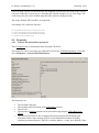
3.14 Properties
Properties are attributes associated with a specific object.
Right now Properties are used for CH10 Files, Channels and Subchannels and Packets.
Properties are subdivided in different categories.
Properties are accessed by right-clicking the object and selecting Properties from its context
menu. This works for example on the CH10 Files within the FLIDAS Repository View, for
Channels and Subchannels in the Channel View and for Packets in the Packet View.
3.15 Views
View is the term that is used for a window with a specific behavior. The term is taken from
the Eclipse framework that is used by FLIDAS.
For a detailed discussion of Views you can look up the Internet and read about Eclipse Views.
However some basic ways of arranging the Views on the screen should be explained here:
Double-click the Views title to resize it to fill the whole window. Double-click it again
to size it normal
Drag the title bar next to the title bar of another View (like the FLIDAS Repository
View). It will then be stacked with the other View.
Drag the title bar to another position inside the main window. The area will be split
between this View and other existing Views. Some indicators will show where it will
be placed
Drag the line between two Views to resize them
Also notice that some Views have icons to their top right to execute further standard or
individual actions.
Views that relate to a specific CH10 File have a colored bar around it that can be configured
individually for each file in the General File Information Properties
To make better use of your screen in a multi-monitor configuration, you can also detach
Views from the main window. To do so, simply drag them outside. You can re-attach them
when you drag them inside the main window and place them in a stack with other Views.
Note that you need to drag the Tab of the View and not the detached windows title bar.
3.16 Error logging
Whenever an error occurs it will be written to the error log. Some of them will also pop up to
inform you. "Errors" are categorized in Errors, Warnings and plain Information.
To show the Error Log View select Window > Show View > Error Log. You can doubleclick on an entry to get more information.
30 / 145
FLIDAS User Manual 2.10.1
Data Bus Tools
If you need the error log as a file (e.g. to send it in with an error report), you will find it below
your installation directory in the subdirectory workspace/.metadata. The file name is .log.
The files and subdirectories may appear hidden on some operating systems.
3.17 ICDs
ICD stands for Interface Control Document. This type of document describes information
going into and coming from a system. Most avionic systems have an ICD that describes the
Parameters circulating on their digital data buses.
In FLIDAS you need to define an ICD to be able to interpret recorded raw data as engineering
units. These ICDs may have different formats depending on the type of data. It is possible to
request support for company internal ICD formats which allows for very unique handling and
saves you from entering and maintaining additional ICDs.
Currently there are file based and hard coded ICDs. Other types like data base related are
possible for the future.
ICDs are intended to be created outside of FLIDAS (like in Excel or with your already
existing company internal tools).
ICDs don't need to be complete. You can also just enter a few Parameters that you need and
extend them over time.
ICDs are used by FLIDAS with the ICD mapping.
Parameters within ICDs can be organized in hierarchical groups to keep a better overview.
For example MIL 1553 Parameters could be grouped by their source RT address and then
finer grouped by the messages within this RT. This hierarchy is completely for organizational
purposes and carries no further information used by FLIDAS other than a name and a parentchild relationship between the container and the contained Parameters. Therefore you can also
organize by other means like engine and navigation Parameters or completely leave out this
type of organization. However this hierarchy will help you to keep an overview when
selecting Parameters within the Parameter Set View. The hierarchy of the names of the groups
will form a Path to the Parameter within this ICD. This Path will be stored within Parameter
Sets. Therefore changing the names in the hierarchy will corrupt Parameter Sets.
The reference chapter for ICD formats lists the available ICD types.
ICDs are only supported in the commercial parameter version.
3.18 Parameters
A Parameter is a single signal that can take different values over time. Parameters are decoded
from the CH10 raw data to an engineering unit level.
Parameters need some information to be defined:
1. General information: Name and engineering unit
31 / 145
FLIDAS User Manual 2.10.1
Data Bus Tools
2. Addressing: Where can the raw data be found within a communication line? These can
be things like word and bit positions and length, ARINC 429 Label and SDI, MIL
1553 RT and Subaddress etc.
3. Decoding: How is the raw data converted to engineering units? These are things like
data type (BCD, Two's complement ...), scaling, enumeration definition etc.
4. Channel / Subchannel mapping: Which electrical line the parameter is found on?
In FLIDAS the first three groups of information are defined in ICDs. The Channel /
Subchannel Mappings are defined by the ICD Mapping in order to reuse ICDs with CH10
files with different Channel / Subchannel setup.
Parameters from an ICD cannot be used directly. Parameters are grouped to Parameter Sets
for use.
Parameters are only supported in the commercial parameter version.
3.19 Parameter Sets
Parameter Sets are groups of Parameters for a specific test / analysis situation. You can for
example create sets for primary flight information and status information on the status of the
electrical system.
Other functions of FLIDAS allow using these Parameter Sets for example as a selection of
Parameters to display. Joining of Parameter Sets and temporary modification are supported.
Parameter Sets depend on an active ICD Mapping to provide the Parameter definitions
through the connected ICDs. The Parameter Sets store the Parameter name, Path and a
"Mapping ID" defined in the ICD Mapping and use these to identify the Parameter definition.
The use of the Mapping ID allows reusing stored Parameter Sets over changing ICD
Mappings. If any Parameter of a Parameter Set cannot be found through the ICD Mapping it
is considered an "unlinked Parameter". These are indicated as a warning.
Parameter Sets are edited in the Parameter Set View.
Obviously working with larger Parameter Sets will impact the performance when decoding
the data from the CH10 File. You should therefore consider making them only as big as
needed. The separation into separate Parameter Sets that can be joined on request should help
you with the management of smaller sets. In general adding a Parameter of a previously
unused Channel will decrease the performance more than adding an additional Parameter
from an already used Channel (Subchannels don't matter). All used Parameters increase the
memory footprint equally if you are working with Parameter Viewers (not Parameter
Exporters. If you run into memory problems the FAQ offers a solution.
Parameter Sets are only supported in the commercial parameter version.
3.20 ICD Mapping
An ICD mapping associates ICDs with Channel and Subchannel numbers. In effect this
defines which Parameters are available and where to find them in a CH10 File.
32 / 145
FLIDAS User Manual 2.10.1
Data Bus Tools
ICD Mappings are intended to be used over a broader range of CH10 Files. This works as
long as they record the same physical communication lines on the same Channels and
Subchannels. ICD Mappings need to define only the data you want to decode to engineering
values, so a variation in Channel and Subchannel numbers on other data is acceptable.
An ICD Mapping is therefore independent of a CH10 File but can be created using a concrete
CH10 File as template.
You can only select one ICD Mapping at any time and this can also be auto selected via the
default directories and files Preferences. If you have several CH10 Files that may use the
same mapping you can still work with them in parallel.
An ICD Mapping can have an active or inactive state. Only the active state loads the
Parameters from the ICDs. Therefore most functions are only available with an active ICD
Mapping. Especially Parameter Sets rely on an active ICD Mapping.
ICD Mappings also store links to Parameter Sets ("associated Parameter Set") that can be
used with this ICD Mapping. These are just shortcuts and unassociated Parameter Sets can
still be used.
ICD Mappings are only supported in the commercial parameter version.
3.21 Parameter Viewers
A Parameter Viewer is a mechanism to display engineering values of Parameters over time.
Parameter Viewers are invoked from the Parameter plug-in control View or Parameter Set
View. They may need some time to process but you can continue working while loading.
Most Parameter Viewers will allow canceling the loading and will then show the data
processed so far instead of the whole time span's data.
Parameter Viewers are only supported in the commercial parameter version.
3.22 Parameter sampling
When Parameter's values are collected over a period of time, this is called sampling.
3.22.1 Sampling modes
FLIDAS supports seven modes of sampling that can be used to generate data for Parameter
Viewers and Exporters. Not all are available everywhere.
Time discrete sampling will collect a Parameter's value at equidistant points in time (e.g.
continuously take a value every second).
Asynchronous sampling will use the points in time where Parameters were really recorded
for sampling. If several Parameters are sampled together, all Parameter will be sampled at the
time when any of the Parameters was recorded. This mode has three sub modes that can be
used to reduce the amount of data:
33 / 145
FLIDAS User Manual 2.10.1
Data Bus Tools
Asynchronous Full: This mode collects all the Parameter values that are stored in the
CH10 file.
Asynchronous Change: This mode limits the Asynchronous Full mode to the points
in time where any of the Parameters in the Parameter Set changed its value. I.e. static
values that are just recorded several times will not be sampled again.
Asynchronous Valid Change: This mode further limits the Asynchronous Change
mode by only looking at the points in time where a valid value changed. E.g. if one
value changes from the invalid value "Not measured" to "BCD coding error" it will
not be sampled again. This also indicates that the user is not interested in error details
so he will simply be shown that the value is invalid.
Separate time stamp asynchronous sampling is identical to asynchronous sampling except
that each Parameter will sample independently and will not share its time stamps with the
others. I.e. if Parameter A is sampled, no sample for Parameter B is automatically taken at the
same time. This mode has the same three sub modes as asynchronous sampling only that
sampling occurs independently on each Parameter:
Separate Time Stamps Full
Separate Time Stamps Change
Separate Time Stamps Valid Change
The following pictures visualize the sampling modes with two Parameters P1 and P2. The
boxes indicate recorded measurements while the ovals show samples taken by FLIDAS at the
time of the vertical grey line.
Time discrete sampling with 1000 ms period
Asynchronous Full sampling
34 / 145
FLIDAS User Manual 2.10.1
Data Bus Tools
Asynchronous Change sampling
Compared to Asynchronous Full sampling two sampling points in time are missing at 2.4 and
2.7 seconds. The first one is missing because P1 is not changing but stays at 7 and the second
one is missing because P2 doesn't change and stays at an invalid BCD coding.
35 / 145
FLIDAS User Manual 2.10.1
Data Bus Tools
Asynchronous Valid Change sampling
Compared to Asynchronous Change sampling one sampling point in time is missing at 0.7
seconds because P2 is changing from "Not measured" to "Invalid BCD coding" but all invalid
values are considered equal no matter why they are invalid in this mode.
Separate Time Stamp Full sampling
Compared to Asynchronous Full sampling you see that a second independent time scale
appears on the bottom. Sampling of the P1 Parameter doesn't cause P2 to be sampled at the
same time anymore.
36 / 145
FLIDAS User Manual 2.10.1
Data Bus Tools
Separate Time Stamp Change sampling
Compared to Separate Time Stamp Full sampling the sampling of P1 at 2.4 seconds and P2 at
2.7 seconds is missing because the value stayed the same.
Separate Time Stamp Valid Change sampling
Compared to Separate Time Stamp Change sampling only the error descriptions of the invalid
values on P2 are missing because you are not interested in them here. The third invalid value
at 2.7 seconds has already been suppressed during the Separate Time Stamp Change sampling
mode because it was exactly the same error as directly before. If it would have been different
it would have persisted in the previous sampling mode but would have been removed by this
sampling mode.
3.22.2 Initialization values
37 / 145
FLIDAS User Manual 2.10.1
Data Bus Tools
When starting Parameter sampling the first set of values (initialization values) is found by
looking back up to one second. Values that do not appear during this time (because they are
probably only transmitted at a low frequency or asynchronously) will be indicated as "not
measured".
Collecting initial values will behave differently depending on the sampling mode and if you
are constraining the start time of the sampling or sample from the beginning of the file.
Sampling mode
Time discrete
Asynchronous
Separate time
stamp sampling
Start time
constrained
Start time is begin of recording
Collect initial values from start for a time span smaller
than the sampling period up to a first "nice" time
stamp (e.g. when starting at a time of 0,123456789
seconds and a sampling period of 1 second, it will
Collect initial values collect initial values until second 1).
from one second
No initial value collection. The first result of the
before start until
sampling process will be from the first time stamp
start.
where any of the Parameters was first recorded.
No initial value collection. The first result of the
sampling process will be from the first time stamp
where each Parameter was first recorded.
38 / 145
FLIDAS User Manual 2.10.1
Data Bus Tools
4 Reference
4.1 Help system
You can access the help system with Window > Help Contents.
Many FLIDAS elements offer context sensitive help. To show it:
1. Activate the element you want help for (i.e. click it).
2. Push a key on the keyboard that brings up help. The key depends on the operating
system and is:
o Windows: F1
o Linux: Shift + F1
o Mac: Help
In some cases the links inside the manual link you to a general topic and the information you
are looking for might be in one of the subchapters. So remember to look up the current section
in the table of contents and look out for subchapters (the help system has an icon in the
toolbar to the top right for this).
The PDF version of the manual is generated from the online help so both have the same
contents.
4.2 Views
4.2.1 FLIDAS Repository View
The FLIDAS Repository view shows all files that are currently loaded and their assigned
color. It is the place where most actions on a file can be invoked.
The FLIDAS Repository view opens automatically when you have finished loading a new
file. You can also bring it up by clicking Window > Show View > FLIDAS Repository.
Each file shows a color in the Repository View. This color is reused in other Views that deal
with data of this file.
39 / 145
FLIDAS User Manual 2.10.1
Data Bus Tools
The Result column shows the result of loading the file. This should normally be OK but
could also indicate an incomplete load in red color. The specific results are described in the
CH10 Files section.
If you right-click the file, you will see several actions to invoke on the file. See the links
below for a closer description:
Show Channels: Shows the Channels and Subchannels of the file with some TMATS
properties. A double-click on the file has the same effect.
Show TMATS: Shows the raw TMATS of the file
Show Packets: Shows all Packets from the file
Show Invalid Packets: Shows all Packets from the file that had an error on Packet
level. This feature is only available in the commercial version.
Show Recording Event Definitions: Shows the Recording Event Definitions from
TMATS
Show Time Markers: Shows the Time Markers associated with this file
Export: Exports various data to other file formats
Create ICD Mapping template: This menu entry is only available in the commercial
parameter version. It creates an ICD Mapping based on the Channels and Subchannels
of the selected CH10 File.
Close File: Closes the file and all associated views.
Properties: Shows the CH10 Data Type Filters, General TMATS attributes and some
General File Information. It also allows you choosing a color for the file.
The yellow icon in the FLIDAS Repository View's toolbar opens a new file.
4.2.2 Packet View
The Packet View shows the Packets within a file in the order that they appeared there together
with some Properties.
To show the regular Packet View right-click the file in the FLIDAS Repository View and
select Show Packets.
There is a second mode of the Packet View which just shows the Packets of one Channel.
This mode is accessed in one of the following ways:
Right-click a Packet in the Packet View and select Show Channel's Packets
Double-click a Channel in the Channel View
.
A third mode of the Packet View just shows corrupted Packets. This mode is accessed from
the FLIDAS Repository View with a right-click on the file by selecting Show Invalid
Packets (only commercial version).
The colored border around the View matches the color in the FLIDAS Repository.
40 / 145
FLIDAS User Manual 2.10.1
Data Bus Tools
You can drag the table column headers of the Packet View and place them between other
column headers. You can also resize the columns when you drag the area between two
column headers. The icon on the right top of the view saves the setup for the next session.
The table shows some data about each Packet:
Time: The timestamp of the Packet up to nanoseconds
Chan#: The number of the Channel the Packet belongs to
Type: The type of the data Packet (like ARINC 429, Ethernet etc.)
Errors: Any errors that have been detected on the Packet (Packet Sync, Packet Header
Checksum, Secondary Header Checksum, Data Checksum, Data overflow, RTC sync).
If there was any error, the background color of the row will also be red.
Data: Any further information interpreted from the Packet. More information can be
found in the supported CH10 Data Types section and depends on the Packet type.
Double-clicking a Packet shows its Packet Entries in the Packet Entry View.
The red arrow buttons in the upper view menu allow navigating between Packets with errors.
They jump from the current selected Packet to the previous or next Packet with an error. If no
Packet is selected, the search will start from top or bottom. The search will not wrap. The
function is only available in the commercial version.
To show the Properties of the Channel of the Packet, right-click the Packet and select
Channel Properties.
To show the detailed Properties of the Packet, right-click the Packet and select Packet
Properties.
To show the Packet's raw content in hexadecimal, right-click the Packet and select Show in
hex. This is only available in the commercial version.
To show the selected Packet in an unfiltered Packet View, right-click the Packet and select
Show within all Packets. This can be used when you want to see which Packets are found
before/after your selected Packet but you have filtered for the Packets of a single Channel or
for corrupted Packets. The feature is only part of the commercial version.
41 / 145
FLIDAS User Manual 2.10.1
Data Bus Tools
To create a Time Marker for a Packet, right click it and select Create Time Marker.
If the Packet View is limited to Packets of a specific Channel, you can jump to the Packet at a
Time Marker. To do so use the icon on the right top of the view. The view will locate the
Packet right before or at the time (or after if the time is before first Packet).
To see how to export all the visible data of the table to a CSV text file read the section about
table exporting.
4.2.3 Packet Entry View
The Packet Entry View hosts a Packet Entry Viewer to display the content of Packets.
You can open it with a double-click on a Packet in the Packet View.
The above screenshot shows the commercial version with MIL 1553. It looks different
depending on the CH10 Data Type and if the version is commercial or free.
The Packet Entry View consists of up to three areas:
The Packet area shows the data about the Packets that's content is displayed here. You
can also show the content of several Packets by using the yellow arrow buttons on top
of the view. The left arrow will increase the range of displayed Packets content by one
Packet at the beginning, the right arrow will add a Packet to the end.
The Packet Entry area shows the Packet Entries of the Packets in the above Packet
area
The third area is optional and can contain additional information depending on the
CH10 Data Type. Analog Packets will for example display a graphical plot of the
samples there.
Each of the three areas can be expanded/collapsed by left-clicking at each areas top bar.
The Packet Entry View can be configured to stay synchronized with the Packet selection in
the Packet View of the same file (i.e. same color code). It will then update when you select a
new Packet. You can control this linking between the Packet selection and the Packet Entry
View with the "Link with selection" icon in the View's toolbar.
42 / 145
FLIDAS User Manual 2.10.1
Data Bus Tools
When you are scrolling through Packets using the keyboard, there is a small delay before
synchronizing the Packet Entry View. This is to avoid overloading the system when scrolling
fast. Packet selections with the mouse will be executed immediately.
The red arrow buttons in the upper view menu allow navigating between Packet Entries with
errors. They jump from the current selected Packet Entry to the previous or next Packet Entry
with an error. If no Packet is selected, the search will start from top or bottom. The search will
not wrap. The function is only available in the commercial version.
You can change and save the column layout in the same way like in the Packet View. This
will also save the "Link with selection" option.
To see how to export all the visible data of the table to a CSV text file read the section about
table exporting.
To show the Properties of a Packet right-click a Packet and select Packet Properties.
To show the Properties of the Channel of the Packets right-click the top bar of any of the three
areas and select Channel Properties.
To create a Time Marker for a Packet or Packet Entry, right click it and select Create Time
Marker.
4.2.4 Channel view
The Channel View shows Channels and Subchannels from one CH10 File together with some
of their Channel and Subchannel Properties. It also allows some actions on these Channels
and Subchannels.
To see the Channel View, double-click a file in the FLIDAS Repository View.
You will see a hierarchy with the Channels being on top and the Subchannels organized as
children below. You need to click on the "+" symbol in front of a Channel to see its
Subchannels.
43 / 145
FLIDAS User Manual 2.10.1
Data Bus Tools
The information has been extracted from TMATS and CH10 File parsing.
Disabled Channels will be indicated with a grey background.
The table shows these columns:
Number: The number of the Channel or Subchannel.
Name: The name of the Channel or Subchannel.
Type: The CH10 Data Type of the Channel
Format: The format of the Packets as used in IRIG 106 chapter 10
IRIG Revision: The IRIG 106 Chapter 10 document revision that the Packets on this
Channel stick to
# Packets: The number of Packets of this Channel found while parsing this file (taking
into account the CH10 Data Type Filter)
2nd headers: If secondary headers are used
Data checksum type: If checksums are used for the data and which type
Problems: FLIDAS does a quick check of the availability of some TMATS attributes
of Channels and Subchannels that are needed for some FLIDAS functionality. If
problems are detected, an indication is shown in red. Details can then be found with a
right-click and selecting Show problems. There will be an additional warning after
loading the file. Problems detected here do not always indicate an incorrect TMATS
file. Files may be correct and perfectly valid and still do not contain enough
information for some FLIDAS functionality. You can try to provide additional
TMATS attributes by TMATS overriding
Additional properties: More Properties that are specific to the CH10 Data Type. This
is the place where the free version lists these Properties. For the commercial version
you can see them also in the Channel and Subchannel Properties (right-click >
Properties).
To see more detailed Properties on the Channels and Subchannels, right-click the Channel or
Subchannel and select Properties.
To see the Packets of one Channel in sequence, double-click it. You can also right-click it and
select Show Packets. The Packet View will open for this Channel. This is not possible for
Subchannels since each Packet may contain data of several Subchannels.
To see how to export all the visible data of the table to a CSV text file read the section about
table exporting.
You can export data from some kind of Channels or Subchannels by right-clicking it and
selecting Export and the appropriate type from the menu. For more information see the
Exporters section.
There are specific options on some elements that start a Protocol Viewer.
You can change and save the column layout in the same way like in the Packet View.
4.2.5 TMATS View
The TMATS View shows the TMATS setup of a CH10 file.
44 / 145
FLIDAS User Manual 2.10.1
Data Bus Tools
To see the TMATS View, right-click the file in the FLIDAS Repository View and select
Show TMATS.
You will see the uninterpreted TMATS data. For interpretations see for example the Channel
View and the General TMATS attributes.
The TMATS view allows searching inside the TMATS data by entering your keyword in the
search term field on top and clicking Next or Previous for forward or reverse search. The
search will look for the exact, case sensitive search term entered.
4.2.6 Recording event definition view
The Recording Event Definitions View shows Recording Event Definitions from the TMATS
section of the file.
To show it right-click the file in the FLIDAS Repository View and select Show Recording
Event Definitions.
The table shows a hierarchy with the Recording Event Channel on the top and the defined
events as its children.
The following Properties are decoded (for reference the TMATS-ASCII codes are given in
italics):
Event number (counted up from 0 for each event)
Event ID (R-x\EV\ID-n)
Event description (R-x\EV\D-n)
Event priority (R-x\EV\P-n)
Recording Event limit count (R-x\EV\LC-n)
Event type (R-x\EV\T-n)
Event capture mode (R-x\EV\CM-n)
Event initial capture (R-x\EV\IC-n)
You can change and save the column layout in the same way like in the Packet View.
To see how to export all the visible data of the table to a CSV text file read the section about
table exporting.
4.2.7 Hex Packet view
45 / 145
FLIDAS User Manual 2.10.1
Data Bus Tools
The Hex Packet View allows analyzing a Packet's raw bytes from the file. It can be used to
debug corrupted files or prepare test data by manipulating existing files. It is only available in
the commercial version.
To open the Hex Packet View, right-click a Packet in the Packet View and select Show in
hex.
You will see the content of the Packet byte by byte on the left. The displayed content will be
limited to one megabyte, which is enough to see all regular Packets even if they are corrupted
and exceed their size by 100%. Only TMATS Packets which may be up to 128 MB are
affected.
The sections of the file will be marked in color if the Packet is valid and the sections could
therefore be safely recognized. The sections are:
Packet header (yellow)
Optional Packet secondary header (green)
Packet body (cyan)
Optional Packet trailer (magenta)
For some CH10 Data Types the Packet body will be further decoded to:
Channel specific data word (orange)
Packet Entries (alternating in two different blue colors to show the different entries).
This will also include fillers at the end of the Packet Entry unless they are part of the
Packet trailer.
The CH10 Data Types supported for this are:
ARINC 429
CAN bus
Ethernet
AFDX
Discrete
MIL-STD-1553
PCM
UART
MPEG Video
46 / 145
FLIDAS User Manual 2.10.1
Data Bus Tools
To the right there is a table which interprets the data that is currently selected. You can select
a byte with the mouse or navigate with the keyboard to select something. The table will show
the meaning of this byte or a group of bytes to the right in different formats like unsigned,
signed (two's complement), binary or hexadecimal. The selection above the table controls if
the interpretation of several bytes uses little or big endian.
If you select a line in the interpretation table, the data bytes that apply to this line will be
printed in bold font in the packet content to the left.
To see the Packet Properties, right-click inside the data and select Packet Properties.
4.2.7.1
Data manipulation
It is also possible to edit the data in the CH10 file. In many environments this would be
strictly forbidden and therefore FLIDAS must be started with a specific command line option
to enable this. There are also safety questions so it is not possible to manipulate the data
accidently.
The function is intended for recorder or software developers or people who verify their new
CH10 equipment. In this case you might want to use a real recording and inject a specific
error at one place (like a parity error or wrong time stamp). You can then replay the data and
see how your equipment behaves.
The changes are directly written back to the source file so you need to make a copy in
advance if you need one.
The feature is intended for small, non-structural changes. It is not possible to add packet
entries, packets etc. It should only be used by people who are very familiar with the CH10 file
format.
FLIDAS loads packet header data and channel specific data words in the initial loading of the
file. Changes here would only take effect during the next loading. This means you might need
to reload the file after one change before applying the next change. If you change the
checksum type from 8 to 16 bits for example, changes in the packet body would still generate
the 8 bit checksum until you reload the file.
To enable manipulation you must start FLIDAS with a command line option. There are two
ways to do this:
The directory that contains the FLIDAS executable also contains a file named
FLIDAS.ini. This file contains default command line options. It contains two lines
reading:
-ch10Modification
deny
You need to change the text "deny" to "allow". Do not add any whitespaces here. If
the two lines have been removed for some reason you can add them before the line "vmargs".
47 / 145
FLIDAS User Manual 2.10.1
Data Bus Tools
A second option is to remove the two lines mentioned in the previous option from the
FLIDAS.ini. You can then start the FLIDAS executable from the command line and
pass the option "-ch10Modification allow". This way you can decide each time you
start if you need modification or not. Of course you can also create two Windows
batch files to start FLIDAS with either of the options.
The command line options will be case insensitive and will default to no modification in case
of spelling errors.
To modify a position in the Packet, locate the position with the cursor and double-click in the
interpretation table. You will be able to edit the data in the format of the line you have clicked
at (i.e. endianness, byte size, hex/bin/unsigned/signed/ASCII applies here).
If the changed bytes are covered by any checksum you will be asked if you want to update the
checksums. If the Packet is corrupted, the positions of the checksums will not be known and
can therefore not be updated.
It is not possible to insert or delete bytes, only overwriting. This is mainly useful for setting
error flags.
4.2.8 Parameter plug-in control View
The Parameter plug-in control View controls the main actions available in the commercial
parameter version. It controls the life cycle of ICD Mappings manages Parameter Sets and
allows Parameter based export and display functions.
The Parameter plug-in control View is opened by clicking Window > Show View >
Parameter Plug-in Controls or using the keyboard shortcut Alt+P.
4.2.8.1
ICD Mapping Management
The upper area shows some buttons for managing the current ICD Mapping.
To create a new ICD Mapping click the New button. This also opens the ICD Mapping View
to edit the new ICD Mapping. Note that you can also create a template of an ICD Mapping by
right-clicking a CH10 File from the FLIDAS Repository and selecting Create ICD Mapping
template.
48 / 145
FLIDAS User Manual 2.10.1
Data Bus Tools
To select an ICD Mapping click the Select button. A selected ICD Mapping just serves as a
preselection for other actions like editing and activation. The selected file will be shown to the
right of the buttons.
To edit an ICD Mapping click the Edit button. The ICD Mapping View will open.
To activate an ICD Mapping click the Activate button. This may take some time if you have
big ICDs but the progress will be reported and the activation can be cancelled. When
activating has finished the displayed file name of the ICD Mapping will be shown in green
color and the button text will switch to Deactivate to deactivate the ICD Mapping again.
Deactivation requires that you close all open Parameter Sets before because they depend on
an active ICD Mapping.
As soon as the ICD Mapping is activated, the Parameter Set based function below become
active.
4.2.8.2
Parameter Set Management
Below the ICD Mapping area, there are two further areas for managing Parameter Sets.
The associated Parameter Sets area shows Parameter Sets that are listed within the ICD
Mapping file as applicable to the ICD Mapping. These are shortcuts to work with them. A
right-click brings up several actions on the listed Parameter Sets. Note that you can select
more than one set at a time to join the selected Parameter Sets to one without duplicates.
To open a Parameter Set click Show Parameter Set. You can also simply doubleclick it as a shortcut. This shows the Parameter Set View which allows modification of
the Parameter Set and export and view actions on the modified set. If you select
several Parameter Sets you can store the joined Parameter Set to a new file or just use
it for a one-time purpose.
To export Parameter values click Exporters and select the appropriate one. See the
Exporters section of the manual to see a list of all Exporters.
To view Parameter values on the GUI click Parameter Viewers and select the
appropriate one. See the Parameter Viewer section of the manual to see a list of all
Parameter Viewers.
The unassociated Parameter Sets area allows working with Parameter Sets that are not listed
within the ICD Mapping file as applicable to the ICD Mapping.
To open a Parameter Set click Open and choose the files. This opens the Parameter
Set View which allows modification of the Parameter Set and export and view actions
on the modified set. If you select several Parameter Sets you can store the joined
Parameter Set to a new file or just use it for a one time purpose.
To create a new Parameter Set click New. This opens the Parameter Set View on the
empty set. You can also use the new set without saving for a one time selection of
Parameters to run actions on it.
4.2.9 ICD Mapping View
The ICD Mapping View is used to display and edit the ICD Mapping.
49 / 145
FLIDAS User Manual 2.10.1
Data Bus Tools
This view is only available in the commercial parameter version.
There are several ways to open an ICD Mapping View:
You can open it with an empty ICD Mapping with the New button in the Parameter
Plug-in Control View
You can open an existing one when you select it and use the Edit button in the
Parameter Plug-in Control View
You can create a new ICD Mapping from a CH10 File as a template and immediately
open it by right-clicking the CH10 File in the FLIDAS Repository and selecting
Create ICD Mapping template
Any modification you do to the ICD Mapping can be saved using the Save ICD Mapping
button in the lower part of the View. If you close the view without saving, you will get the
chance to save before. If you have edited the active ICD Mapping this will not apply the
changes until you deactivate it and activate it again using the Parameter Plug-in Control View.
The two other areas of the View cover the Channel / Subchannel ICD Mapping management
and the associated Parameter Sets.
4.2.9.1
Channel / Subchannel ICD Mapping
The upper area of the View is occupied by a table showing a hierarchy of all Channels and
Subchannels defined for the ICD Mapping. This can be less than the Channels and
Subchannels of the CH10 Files you apply this mapping to but should not be more. The table
has these columns:
ID: The Channel or Subchannel number as occurs in the CH10 File. Note that some
TMATS setups use a different numbering system than the CH10 Files. See also the
FAQ for this.
Mapping ID: This is a user definable mnemonic for the Channel or Subchannel. For
example if it records your air data computer it could be ADC. This Mapping ID is
stored in Parameter Sets to identify which ICD the Parameter definition should be
taken from. This decouples the Parameter Sets from the ICD Mapping, so you can use
different Channel assignments and ICD Mapping files but will still be able to reuse
Parameter Sets as long as you keep the Mapping ID consistent. The Mapping ID may
be any text but not contain "#".
50 / 145
FLIDAS User Manual 2.10.1
Data Bus Tools
Type: The CH10 Data Type
Format: The data type format as defined in IRIG 106 Chapter 10
ICD type: The type of the ICD. This may be a standard one provided with FLIDAS or
can also be a proprietary extension to support your company internal definitions
formats.
ICD resource type: The type of the resource that contains the ICD definition.
Currently this can be a file or hard coded within a FLIDAS Plug-in. Future extensions
may be other types like databases.
URI: A link to the resource that defines the ICD if needed. This may currently only
refer to a file.
You can change and save the column layout in the same way like in the Packet View.
You have these options to modify the Channel and Subchannel Mapping definition:
To add a Channel ICD Mapping right-click another Channel (or select nothing and
right-click) and select Add Channel. An edit dialog pops up that is described later.
To add a Subchannel ICD Mapping right-click the enclosing Channel and select Add
Subchannel. An edit dialog pops up that is described later.
To remove a Channel or Subchannel right-click it and select Remove. If you remove a
Channel its Subchannels will also be removed.
To modify a Channel or Subchannel right-click it and select Edit. An edit dialog pops
up that is described below.
The edit dialog allows modifying the ID, Mapping ID and mapped ICD as defined above. To
map another ICD, click at Select ICD and select the type from the ICD type drop down list in
the upcoming dialog. You can select None to clear the ICD mapping. If you select a file you
can store an absolute or relative path. Relative paths will be relative to the location of the ICD
Mapping file.
Editing a Channel also allows modifying the CH10 Data Type and format. These also affect
the Subchannels and may invalidate Subchannel ICD Mappings. In this case you get a
warning.
4.2.9.2
Associated Parameter Sets
This area of the View shows Parameter Sets that are intended to be used with this ICD
Mapping. They are shown as shortcuts in the Parameter Plug-in View when the ICD Mapping
is active. It is still possible to use other Parameter Sets.
To associate more Parameter Sets right-click the list and select Add. You can select one or
more Parameter Set files in the following file dialog. You can choose to store absolute or
relative paths to the files. Relative paths will be relative to the ICD Mapping file.
To remove associations to Parameter Sets select one or more from the list and select Remove
4.2.10 Parameter Set View
The Parameter Set View is used to display and edit Parameter Sets. It also allows running
export and display actions on the selected Parameter values.
51 / 145
FLIDAS User Manual 2.10.1
Data Bus Tools
This view is only available in the commercial parameter version.
There are several ways to open a Parameter Set View:
You can open it with an empty Parameter Set with the New button in the Parameter
Plug-in Control View in the area for unassociated Parameter Sets.
You can open an existing one with the Open button in the Parameter Plug-in Control
View in the area for unassociated Parameter Sets. If you select several Parameter Sets
at once you get a new, unsaved Parameter Set with the joined content of the selected
ones.
You can open an existing one that is associated with the ICD Mapping when you
right-click it in the Parameter Plug-in Control View in the area for associated
Parameter Sets and select Show Parameter Set. If you select several Parameter Sets
at once you get a new, unsaved Parameter Set with the joined content of the selected
ones.
Any modification you do to the Parameter Set can be saved using the Save Parameter Set
button in the lower part of the View. If you close the view without saving, you will get the
chance to save before. However often you will just use this View for a temporary selection of
Parameters for a one-time action.
In this View you may see up to three tables. The column layout of all tables can be saved in
the same way like in the Packet View. You can redistribute the space between the tables by
dragging the lines between the tables.
The table Available Parameters shows a hierarchy of all Parameters available through the
active ICD Mapping. They are grouped by the Mapping ID associated with the Channel or
Subchannel and further hierarchical grouping defined by the ICD. They appear in the order of
the ICD definition. You can select and deselect Parameters for the Parameter Set by using the
check boxes in front of the Parameter name. You can also select / deselect all Parameters in a
hierarchy segment by using the check box at a higher level in the hierarchy. Be careful as
performance of working with Parameter Sets degrades with the number of selected
Parameters. The table also shows some basic information about the Parameter format and the
associated comment.
52 / 145
FLIDAS User Manual 2.10.1
Data Bus Tools
The table Selected Parameters shows all Parameters from the Parameter Set that are valid in
the active ICD Mapping with their Mapping ID, path, name, comment and some information
about the format. The order within the table is used by actions run on this Parameter Set like
exporting or displaying. You can change the order by selecting one or more and using the up /
down arrow buttons to the right. You can also deselect one or more Parameters by selecting
them, right-clicking and selecting Remove.
The table Unlinked Parameters shows all Parameters from the Parameter Set that are invalid
in the active ICD Mapping and is only visible when such Parameters exist. Invalid means the
combination of Mapping ID and Parameter path and name is not found. These Parameters will
be unavailable when you use this Parameter Set and will trigger additional warnings. The
unlinked Parameters show their Mapping ID and name to help you searching the problem. If
you want to remove unlinked Parameters from the Parameter Set, select one or more, rightclick them and select Remove.
The View / Export button allows running export and display actions related to the current
selection of Parameters:
To export Parameter values click View / Export and select Export and the
appropriate Exporter. See the Exporters section of the manual to see a list of all
Exporters.
To view Parameter values on the GUI click View / Export and select Parameter
Viewer and the appropriate Parameter Viewer. See the Parameter Viewer section of
the manual to see a list of all Parameter Viewers.
4.3 Packet Entry Viewers
The visualization of Packet Entries within Packets as shown in the Packet Entry View will in
general be according to the following standard. Some Packet Entry Viewers deviate from this
and are described in the subchapters.
In the free version of FLIDAS the Packet Entries will always be shown in a table with a
timestamp and a second column containing all further data in an unformatted text string.
The commercial version of FLIDAS contains more specific tables for the data that spread it
out in separate columns and possibly offer other visualizations (like graphs) and further
attributes. They also show Packet Entries with errors with a red background color (only errors
directly indicated in IRIG 106 Chapter 10 specification).
The Packet Entry Viewers generally show the Properties as indicated in the CH10 Data Type
Support section. Data payload will be limited to a reasonable amount (first 32 in most cases).
The Property format (hexadecimal, binary etc.) is given in the column headers tooltips (text
shown when hovering with the mouse over the header) if not decimal.
4.3.1 Analog Packet Entry Viewer
The Packet Entry Viewer for the analog CH10 Data Type shows not only the decoded
Properties in a table but also shows a graph of each analog Subchannel for visual recognition
of the nature of the signal and possible anomalies.
53 / 145
FLIDAS User Manual 2.10.1
Data Bus Tools
If the Packet Entry View shows several Packets, the Packet Entry table will list one Packet
Entry for each Subchannel of the first Packet before continuing with the next Packet and so
on.
Each Subchannel will get an own horizontal stripe for its graph including a horizontal axis for
the 0 value.
The stripes will appear in the same sequence as for the first Packet in the Packet Entry table
above. They will contain the joined samples of all displayed Packets of its Subchannel.
The horizontal axis will spread the whole Packets range over the whole width of the View.
The vertical axis will be scaled to the full bit range for integer samples (e.g. 0..255 for
unsigned 8 bit, -128 .. 128 for signed 8 bit (not -128 .. 127 in order to have symmetric range)).
Floating point samples will be scaled to a symmetric range around 0 so that the
maximum/minimum value of the Packet Entries of the Subchannel fits just in the scale (i.e. if
the samples range from -3.2 .. 5.7 the scale will go from -5.7 .. 5.7).
Neither of the axes will show a scale.
If the graphs cause performance issues especially for very high sampling frequencies or the
display of many Packets at the same time use the Packet Entry Viewers Preferences.
4.3.2 PCM Packet Entry Viewer
The Packet Entry Viewer for PCM CH10 Data Type shows not only the decoded Properties in
a table but also the separation of the PCM data of the selected Packets into PCM minor
frames.
54 / 145
FLIDAS User Manual 2.10.1
Data Bus Tools
The table in the third area of the Packet Entry View will list the PCM minor frames with the
following columns:
A time stamp
The state of the minor and major frame synchronization
The hexadecimal frame synchronization pattern
The decimal subframe word positions decoded from all subframe ID counters
The hexadecimal data words. Each shows just enough hex digits to contain the
individual data word's maximum bit length. You can limit the amount of columns for
data words in case of performance issues or operating system problems with the
Packet Entry Viewer Preferences.
To create a Time Marker for PCM minor frame, right click the line and select Create Time
Marker.
4.4 Preferences
4.4.1 General Preferences
The general Preferences collect some settings that are globally active in the application that
do not fit in somewhere else.
You can access these Preferences by clicking Window > Preferences > General.
55 / 145
FLIDAS User Manual 2.10.1
Data Bus Tools
The Preferences are:
Check for secondary header and data checksum errors controls if Packet's
secondary headers and data will be checked for checksum errors while loading (the
packet header will always be checked). Invalid Packets will be shown red in the
Packet View. If you skip this check, the loading of files runs faster but checksums are
ignored. You can use this in an environment where errors are unlikely to occur.
Try finding next Packet on wrong Packet sync controls the behavior when a Packet
with a wrong header checksum or Packet sync has been found. You can either skip the
further loading of the file or let FLIDAS try to find the next Packet. When many
corrupt Packets are in the file, this option will decrease loading performance
significantly and finding the Packets is based on a heuristic approach (the next place
with a valid sync, header, secondary header and data checksum will be considered the
next Packet).
Maximum number of unexpected loading errors before termination controls how
many unexpected errors are allowed to occur during the loading of a CH10 File. If this
threshold is met, the loading will terminate. You can still use the data loaded so far.
Only errors not explicitly handled by FLIDAS count against this threshold.
CSV column delimiter defines a default to use to separate table columns when
exporting data to a CSV text file.
Locale configures if FLIDAS uses a different localization than configured for your
computer system. Mainly this controls how time stamps look and which decimal
separator is used when displaying or exporting data or loading ICDs. If you change it
you must restart FLIDAS to take effect. The setting (System default) on top of the list
removes FLIDAS specific localization and uses whatever is configured in your
operating system.
Use Unicode UTF-8 character encoding on text files: Makes sure that all text based
files will be treated as UTF-8 encoded Unicode files. This applies for example to
ICDs, Parameter Sets, ICD Mappings and exported CSV files. In result you can use
Japanese, Chinese or Cyrillic letters for Parameter names and engineering units for
example or use additional mathematical symbols. If not enabled, your default system
character encoding will be used. Some functions especially export file formats (e.g.
Matlab) might restrict the use of Unicode so FLIDAS must make adaptations there.
Scale for default column width allows scaling column widths on tables with a single
preference. This applies only to tables where the column widths have not been
individually configured. You can use this setting if you are using an operating system
setup with bigger fonts. The Linux default for example is different from Windows.
Increasing the value increases the column width proportionally.
4.4.2 CH10 Data Type Filter Preferences
CH10 Data Type Filters control which CH10 Data Types will be loaded from a file at all. For
example you can just focus on ARINC 429 by deselecting all other CH10 Data Types.
You can access these Preferences by clicking Window > Preferences > CH10 Data Type
filters.
56 / 145
FLIDAS User Manual 2.10.1
Data Bus Tools
The CH10 Data Types are listed in two categories:
Supported CH10 Data Types lists CH10 Data Types which are supported by
FLIDAS to a finer grained level. I.e. these will show you details on the data.
Only packet level lists CH10 Data Types which have no further support. These
Packets will be listed as file content but not show any details about their contained
Packet Entries.
When the box in front of a CH10 Data Type Filter is checked it means that the data of this
CH10 Data Type will be available.
The CH10 Data Type Filter for Invalid Packets will control if Packets that have an invalid
packet sync or a wrong packet header checksum will show up as invalid in the Packet View or
if they will be completely suppressed. If they show up, they will not contain valid data. Even
the time stamp will not be correct but will be calculated from the highest RTC value
processed so far. Only their position within the file will be correct.
The CH10 Data Type Filter for Unknown Packets will control if Packets that have a data
type not defined in IRIG 106 Chapter 10 will show up anyway if they are valid in other
respects. If they show up, they will only show their channel specific data word but not contain
any Packet Entries.
CH10 Data Type Filters are also configured when you open a file within the File Loading
Options dialog. This allows you changing the configuration just for this file but based on the
global configuration.
4.4.3 Packet entry viewers Preferences
These Preferences allow a global configuration of the Packet Entry Viewers. It is only
available in the commercial version.
57 / 145
FLIDAS User Manual 2.10.1
Data Bus Tools
To access the Preferences click Windows > Preferences.
The Preferences are:
Suppress analog graphs: The Analog Packet Entry Viewer plots a graph of the
analog samples. This may cause performance issues if many samples are contained in
the displayed Packets. This option can suppress plotting the graph. If you activate it
you must define an upper limit on the number of samples inside the displayed Packets
that you want to plot. If the samples exceed this amount, no plotting will occur at all.
The number of samples takes into account the samples of all Subchannels inside all
displayed Packets.
Limit display of PCM Minor frame data words: The PCM Packet Entry Viewer
displays data words of PCM minor frames spread out into columns of a table. Large
amounts of columns may cause performance issues or even problems in the operating
system (this is known for Windows). Several hundred can normally be handled. This
option can limit the number of columns created for data words. If there are more data
words, a last column will indicate that there is more but leave out the actual data. If
you activate it you must define the upper limit of data words to be displayed in a
minor frame.
4.4.4 Default directories and files
These Preferences set up in which directories you start when selecting a file in a specific
situation. You can still select files of other directories but you need to navigate to this
directory yourself then.
The Preferences also control which ICD Mapping is preselected on start up.
You can access these Preferences by clicking Window > Preferences > Default directories
and files.
The first setting controls the Directory strategy. This defines the mode by which you want to
manage the default directories. FLIDAS distinguishes these directories by situations in which
they are used in (like opening a CH10 file or exporting data). It keeps track of the directories
you used the last time in each of these situations. You can define default directories for most
of these situations. The directory strategy controls if you prefer to use the configured defaults
or the history and it will fall back to the other type if no default or history is available for a
specific situation.
The options for the directory strategy are:
Prefer configured defaults over history
Prefer history over configured defaults
Use system default
58 / 145
FLIDAS User Manual 2.10.1
Data Bus Tools
You can configure default directories for these situations:
Directory where CH10 files are loaded from.
Directory where files are exported to
Directory where ICD Mappings are loaded from
Directory where ICDs are loaded from
Directory where Parameter Sets are loaded from
TMATS override files will be selected from the same directory as the selected CH10 file
unless you select the "prefer history over configured defaults" directory strategy.
4.4.5 User map Preferences
The user map Preferences make maps available for the Navigation data View. You can use
this to replay your flight routes on a local map of your test range.
You can access these Preferences by clicking Window > Preferences > User maps.
These Preferences are only available in the commercial parameter version
The Preferences show a list of files that define your user maps. You can add files by clicking
at the Add button and remove them by selecting a file and clicking Remove.
User map definitions are simple text files with a file extension of your choice. They define
four values in the order given below. Each value must have its own line and have no
additional whitespaces. The values must accord to your configured locale.
1. The latitude of the center of the map in degrees. + means north, - means south.
Fractional values will be interpreted as degrees not minutes. Therefore 3.50 means 3
degrees, 30 minutes.
2. The longitude of the center of the map in degrees. + means east, - means west.
3. The span of the latitude from bottom to top in degrees. E.g. if the top of your map has
a latitude of 51 and the bottom of 50, then the span would be 1 degree. The value must
be positive.
4. The filename of an image of the map including the path.
The image of the map must face north on the upper border.
The projection of the map expects that one pixel in horizontal and vertical direction equals the
same amount of degrees in latitude as in longitude. For example if 1 pixel equals 0.001
degrees in latitude, it must also equal 0.001 degrees in longitude. This is normally not true for
59 / 145
FLIDAS User Manual 2.10.1
Data Bus Tools
maps covering a wider area and therefore the mapping of positions to the map image will get
worse the larger the covered area is. Normally this is good enough to cover a test range. For
wider areas you can use the default maps that offer a precise map projection.
The image formats PNG and JPG are supported.
An example file could look like this:
51.209848083333333333333333333333
13.590704055555555555555555555556
0.80254166666666666666666666666667
C:\temp\test_range.png
4.5 Properties
4.5.1 General File Information properties
These Properties show information about a loaded CH10 File.
The Properties can be seen when you right-click a file in the FLIDAS Repository View and
select Properties > General File Information.
The Properties are:
The file name and path
The loading result (described in the CH10 Files section)
The file size
The amount of Packets that have been found after applying the CH10 Data Type
Filters
The start and end time of the recording will be derived from the minimum and
maximum relative time counters (RTCs) of all valid Packet headers excluding
computer generated Packets (TMATS, recording indices / events, user defined). Since
60 / 145
FLIDAS User Manual 2.10.1
Data Bus Tools
one Packet may contain up to 100 ms of data, the end time will be one million RTC
ticks behind the maximum RTC.
The duration of the recording (based on previous definition of start/end time)
The time Channel ID that has been used. FLIDAS will lock to the Channel of the first
time stamp Packet and will use this as a reference.
If problems have been detected in the TMATS setup of Channels or Subchannels. See
the Channel View for details.
The numbers of Packet errors detected of the following types:
o Packet sync
o Packet header checksum
o Secondary header checksum (if check is configured))
o Data checksum (if check is configured))
o RTC sync
o Data overflow
o Lost Packets (i.e. the number of times a sequence number was not OK, not the
actual number of missing sequence numbers)
o Any of the above errors detected in a Packet
If the checksums of Packets have been checked (see File Loading Options)
If the TMATS file has been overridden the file is shown.
A button to select a new color to associate with this file (will be used in Views related
to this file).
4.5.2 General TMATS attributes properties
These Properties show General TMATS attributes decoded from a loaded CH10 File.
The Properties can be seen when you right-click a file in the FLIDAS Repository View and
select Properties > General TMATS attributes.
61 / 145
FLIDAS User Manual 2.10.1
Data Bus Tools
The properties are only shown when the TMATS attribute was defined. All TMATS attributes
from the General Information Group of IRIG 106 Chapter 9 are decoded. In addition the
original recording date and time (R-x\RI4) is displayed for each data source.
All comments (G\COM) are displayed in the order as they appear but are not displayed in
their context where they appeared.
4.5.3 CH10 Data Type Filter properties
These Properties show which CH10 Data Type Filters were active when loading a file.
The Properties can be seen when you right-click a file in the FLIDAS Repository View and
select Properties > CH10 Data Type Filters.
4.5.4 General Channel and Subchannel properties
These Properties show TMATS attributes and other information about a single Channel or
Subchannel.
The Properties can be seen when you right-click a Channel or Subchannel in the Channel
View and select Channel Properties > General Channel Properties or Properties >
General Subchannel Properties.
Channel Properties are also available with a right-click on a Packet of the Packet View or a
right-click on the Packet area in the Packet Entry View and selecting Channel Properties.
62 / 145
FLIDAS User Manual 2.10.1
Data Bus Tools
The general Channel Properties are (for reference the TMATS-ASCII codes are given in
italics):
Track number / Channel ID (R-x\TK1-n)
Channel enable (R-x\CHE-n)
Data source ID (R-x\DSI-n)
Channel data type (R-x\CDT-n)
Data type format (these are individual attributes of each CH10 Data Type like: Rx\ATF-n, R-x\ABTF-n, R-x\VTF-n ...)
Channel data link name (R-x\CDLN-n)
Channel data type (R-x\CDT-n)
Packet count: The number of packets that have been read (taking the CH10 Data Type
Filters into account)
Packet's IRIG revision: The IRIG 106 revision that the packets stick to.
The general Subchannel Properties are:
The Subchannel name
The Subchannel number. Note that some Subchannels start their numbering with 1
while others start counting by 0. FLIDAS sticks to the numbering system of IRIG 106
but some recorders seem to produce files that use one numbering system in TMATS
and one in CH10 Files which will lead to an invalid mapping of TMATS and CH10
data.
In the commercial version more pages show individual Properties for some CH10 Data Types.
These are described in the CH10 Data Type Support chapter. The free and commercial
versions also show some of these Properties directly in the Channel View in the Additional
properties column.
4.5.5 General Packet properties
These Properties show information that is common to all types of Packets. They are only
available in the commercial version.
63 / 145
FLIDAS User Manual 2.10.1
Data Bus Tools
The Properties can be seen when you right-click a Packet in the Packet View and select
Packet Properties > General Packet Properties.
Packet Properties are also available with a right-click in the Hex Packet View and selecting
Packet Properties.
The general Packet properties are organized by the sections inside the Packet within the CH10
File. They decode all data defined in the Chapter 10 standard for these sections and also some
calculated properties:
64 / 145
FLIDAS User Manual 2.10.1
Data Bus Tools
Packet header:
o A hexadecimal byte by byte representation of the 24 header bytes
o All Properties defined in the chapter 10 document
o The calculated checksum
o When the checksum or packet sync was wrong or any packet flag indicated an
error, the Property will be highlighted in red.
Optional secondary header:
o A hexadecimal byte by byte representation of the 12 secondary header bytes
o All Properties defined in the chapter 10 document
o The calculated checksum
o When the checksum was wrong, the Property will be highlighted in red.
Optional packet trailer:
o A hexadecimal byte by byte representation of the trailer bytes
o All Properties defined in the chapter 10 document
o The calculated checksum
o When the checksum was wrong, the Property will be highlighted in red.
Other Properties:
o The position of the first Packet byte within the file
o The absolute time as calculated from the RTC
o The RTC difference to the previous and following Packet on the same channel
(positive values). Note that the previous and following Packets are not
available for the computer generated data Packets.
o The time difference in nanoseconds like above
o The sequence number difference like above
o Negative RTC differences or sequence number differences unequal to one will
be marked red.
More pages show individual Properties for all Packet types in decoded form and the raw
channel specific data word. These individual Properties are described in the CH10 Data Type
Support chapter. The free and commercial versions also show some of these Properties
directly in the Packet View in the Data column.
4.6 CH10 Data Type support
All CH10 Data Types will be recognized and their Packets will show up with a time stamp
and the Packet level properties in the Packet View. However only some CH10 Data Types are
supported further so that they are decoded into Packet Entries. The following section will
describe which Properties are decoded and are therefore available for display or exporting.
4.6.1 ARINC 429
ARINC 429 Packets have these Properties:
The time stamp
The number of contained messages
ARINC 429 Packets will be decoded to single ARINC 429 messages with these Properties:
The time stamp
The bus speed (Low or High speed (LS/HS))
The number of the Subchannel within this IRIG 106 Channel
65 / 145
FLIDAS User Manual 2.10.1
Data Bus Tools
The parity bit
The SSM
The SDI
The label number
The 19 bit data
An indication when a parity error was detected
An indication when a format error was detected
4.6.2 MIL 1553
The MIL 1553 Packets have these Properties:
The time stamp
The number of contained messages
A definition of the bit within the message that the time stamps refers to
MIL 1553 Packets will be decoded to single MIL 1553 messages with these Properties:
The time stamp
Bus A or B of the dual redundant buses
The message type
The receive and transmit command and status words if present
The command words additionally decoded to RT address, subaddress and word count
The status words additionally decoded to the RT address and flags
The type of the modecode if it was a mode code
The number of data words that have been transmitted
The data words
The detected errors (Format, invalid word, message, response timeout (Rx), response
timeout (Tx), sync type, word count)
The duration of the first and second gap within the message (if any) in 100
nanoseconds (time between data/command word and 1st and 2nd status word)
If a Format, Sync type or Invalid Word error occurred, the words on the bus cannot properly
be decoded into command, status and data words. Instead all words on the bus will be
displayed as data words.
4.6.3 Ethernet
Ethernet Packets have these Properties:
The time stamp
The number of contained frames
The Ethernet packet type
A definition of the bit within the message that the time stamps refers to
Ethernet Packets will be decoded to single Ethernet frames with these Properties:
The time stamp
The physical network ID
The speed
An indication for the following errors in the frame:
66 / 145
FLIDAS User Manual 2.10.1
Data Bus Tools
o
o
o
o
Frame
Frame checksum
Data length
Data checksum
The definition of what has been recorded (full frame vs. payload only). If only the
payload is recorded, some analysis features of FLIDAS are limited on the data.
The number of bytes in the frame
The bytes of the frame
4.6.4 ARINC 664 (AFDX) / UDP payload
The IRIG 106 standard supports AFDX packets and an unspecified Ethernet UDP payload
within the same data type. Most likely AFDX will be the most common in the future.
AFDX Packets have these Properties:
The time stamp
The number of contained messages
AFDX Packets will be decoded to single AFDX Messages with these Properties:
The time stamp
The source and destination IP addresses and ports
The virtual link
An indication when an error occurred in the frame
An indication when the data was simulated data
The number of bytes in the frame
The bytes of the frame
4.6.5 Video
MPEG Video exists in three format variants in IRIG 106 Chapter 10. All of them are handled
quite similar in FLIDAS. The formats 1 and 2 offer the option to have an MPEG program
stream or a transport stream. No sample files were available to us to test with program
streams. Some limited tests have been done with regular MPEG files. So the program stream
decoding is considered experimental and delivered for free.
Note: MJPEG and MJPEG 2000 videos are handled differently in FLIDAS.
Video Channels show these Properties if available (TMATS-ASCII codes given in italics):
An indication if the stream is a program or transport stream
Constant bit rate (R-x\CBR-n)
Variable peak bit rate (R-x\VBR-n)
All video Packets have these Properties:
The time stamp
An indication when a timestamp is encoded within the IRIG106 packet entries
An indication when a timestamp is encoded within the MPEG data
An indication when KLV metadata is present in the MPEG-2 data
67 / 145
FLIDAS User Manual 2.10.1
Data Bus Tools
An indication if the MPEG System Clock Reference is synchronized with the Real
Time Clock of the recorder
Video Packets of format 0 (MPEG-2/H.264) have these additional Properties:
The MPEG-2 payload type
An indication if the video stream uses big or little endian 16-bit byte alignment
Video Packets of format 1 (ISO 13818-1 MPEG-2) have these additional Properties:
An indication if variable or constant bit rate has been used
An indication if the stream is a program or transport stream
The MPEG-2 profile and level of the encoded bit stream
The number of MPEG-2 packets
Video Packets of format 2 ((ISO 14496 MPEG-4 Part10) 110 AVC/H.264) have these
additional Properties:
An indication if variable or constant bit rate has been used
An indication if the stream is a program or transport stream
The MPEG encoding level of the encoded bit stream
The MPEG encoding profile of the encoded bit stream
The type of the contained audio
The number of MPEG-2 packets
The Packets are decoded into single MPEG packets with these Properties:
The time stamp (if there is no time stamp for the packet entries they will share the time
stamp of the packet)
The bytes of the data. Different byte alignment has already been handled.
4.6.6 UART
UART Subchannels show these Properties if available (TMATS-ASCII codes given in
italics):
Baud rate (R-x\UCR-n-m)
Bits per word (R-x\UCB-n-m)
Parity (R-x\UCP-n-m)
Stop bit (R-x\UCS-n-m)
Interface (R-x\UCIN-n-m)
Block size (R-x\UCBS-n-m)
Sync word length (R-x\UCSL-n-m)
Block sync value (R-x\UCSV-n-m)
Block Rate (R-x\UCBR-n-m)
The UART Packets have these Properties:
The time stamp
An indication when the individual UART Packet Entries have separate time stamps
68 / 145
FLIDAS User Manual 2.10.1
Data Bus Tools
The Packets are decoded into UART messages with these Properties:
The time stamp (if there is no time stamp for the packet entries they will share the time
stamp of the Packet)
The UART sub channel number
The number of data bytes
The data bytes
An indication when a parity error was detected
4.6.7 Analog
Analog Channels show these Properties if available (TMATS-ASCII codes given in italics):
Sample rate (R-x\ASR-n)
Data packing option (R-x\ADP-n)
Analog Subchannels show these Properties if available (TMATS-ASCII codes given in
italics):
Measurement name (R-x\AMN-n-m)
Sub channel enabled (R-x\AMCE-n-m)
Data length (R-x\ADL-n-m)
Bit mask (R-x\AMSK-n-m)
Measurement transfer order (R-x\AMTO-n-m)
Recorded analog format (R-x\AF-n-m)
Sample rate (derived from the Channel's sample rate and the Subchannel's sample
factor (R-x\ASF-n-m))
If this is an audio recording (R-x\AV-n-m)
Audio format (R-x\AVF-n-m)
The analog Packets decode these Properties:
The time stamp
The number of subchannels
An indication if the samples are packed
An indication when all subchannels have the same definition
The Packets are decoded into one Packet Entry for each subchannel (in contrary to one entry
for each sample). They have these Properties:
The time stamp (the same as the packet)
The analog Subchannel number
The bit length of each sample
The bit mask of each sample (taken from TMATS)
The analog format, e.g. Two's complement or unsigned binary (taken from TMATS)
The sampling rate divisor, i.e. the number the sampling rate of the channel must be
divided by to get this subchannels sampling rate. Note that this is derived from the
"Sample Factor" but not the same.
The number of samples for this subchannel within this packet
The samples. These have already been masked, probably reversed (only if TMATS
indicates LSB first) and the analog format has been applied.
69 / 145
FLIDAS User Manual 2.10.1
Data Bus Tools
The maximum and minimum sample in this Packet
Decoding is heavily depending on TMATS attributes. If some are missing, you can probably
provide them with TMATS overriding. Also the Analog to CSV Exporter is able to export the
data while correcting some settings.
4.6.8 Discrete
The decoding of discretes is untested due to the lack of sample files. It is provided for free at
your own risk.
The discrete Packets have these Properties:
The time stamp
The number of bits in each discrete Packet Entry
An indication of LSB or MSB alignment of the Packet Entries
An indication if the recording was done on a state change or on equidistant points in
time
The Packets are decoded into Packet Entries with a sample of the discrete bits at the same
point in time. The Packet Entries have these Properties:
The time stamp
The discrete bits in LSB alignment
4.6.9 PCM
PCM Channels show these Properties if available (TMATS-ASCII codes given in italics):
Data packing option (R-x\PDP-n)
PCM code (P-d\D1)
Data randomized (P-d\D7)
Input stream derandomization (R-x\IDDR-n)
Bit rate (P-d\D2)
Common word length (P-d\F1)
Word transfer order (P-d\F2). If this is undefined FLIDAS will default to most
significant bit first.
Words per minor frame (P-d\MF1)
Bits per minor frame (P-d\MF2)
Minor frame sync type (P-d\MF3). Only "fixed pattern" is supported for
decommutation and will be assumed by default. The value "Other" leads to a warning
for the Channel.
Sync pattern length (P-d\MF4)
Sync pattern (P-d\MF5)
In-sync and out-of-sync criteria (P-d\SYNC1) to (P-d\SYNC4)
Words with different length than common word length (P-d\MFW1-n and P-d\MFW2n)
Minor frames per major frame (P-d\MF\N)
All subframe ID counters with these properties:
o Name (SFIDx with x a unique number if the name is undefined) (P-d\ISF1-n)
o Word position (P-d\IDC1-n)
70 / 145
FLIDAS User Manual 2.10.1
o
o
o
o
o
Data Bus Tools
MSB position (P-d\IDC3-n)
Bit length (P-d\IDC4-n)
Bit transfer order (P-d\IDC5-n)
Initial counter value (P-d\IDC6-n)
Counting direction (P-d\IDC10-n)
The PCM Packets have these Properties:
The time stamp
The mode (Packed, Unpacked, Throughput)
An indication if the individual PCM Packet Entries have intra packet headers (only in
packed/unpacked mode)
Whether 16 or 32 bit alignment was used
The sync offset (word offset into the major frame for the first data word in the Packet
Entry) (only in unpacked mode)
The major and minor frame lock status (only in packed/unpacked mode)
An indication if the packet entry starts with a minor or major frame (only in
packed/unpacked mode)
Packed or unpacked PCM Packets will be decoded to Packet Entries (PCM minor frames)
with these Properties:
The time stamp
If a minor and/or major frame lock exists
The subframe word positions decoded from all subframe ID counters
The minor frame sync pattern and the data words. The words are already adapted to
the individual word's bit length and least significant bit first entries have been reversed
(See also Open IRIG 106 issues as this is not properly specified in IRIG 106). As
many hex digits are shown as required to fit the bit length inside.
Each throughput PCM Packet will be decoded to one Packet Entry (as these do not directly
map to PCM minor frames) with these Properties:
The time stamp
The raw data byte wise in transmission order.
The PCM minor frame level is supported for all modes of PCM packets with further features
like the PCM Packet Entry Viewer.
PCM minor frame decoding for PCM throughput mode works like this:
The TMATS attributes for in and out-of sync criteria are used to synchronize into the
bit stream. This is done in the scope of the selected Packets. Therefore when looking
at a subset of PCM Packets, the beginning section and the end section will be lost
because they are no complete minor frame or the synchronization process has not yet
locked in.
If the PCM stream indicates that it is randomized (through P-d\D1 or P-d\D7) and that
the recorder did not derandomize (indicated by R-x\IDDR-n) FLIDAS will do a
software derandomization using the 15 bit derandomization from IRIG 106 Appendix
C. You can use TMATS overriding if your recorder doesn't provide the attributes.
71 / 145
FLIDAS User Manual 2.10.1
Data Bus Tools
The following features are unsupported so far. Contact us if you need some of them:
Parity (currently parity will be considered part of the raw data of a data word)
Any IRIG 106 PCM class II features (except data word length up to 63 bit, unlimited
bit rate, unlimited bits / words per minor frame)
IRIG 106 Chapter 8
Word lengths exceeding 16 bit in unpacked mode are not properly defined in IRIG
106 Chapter 10. See Open IRIG 106 issues.
4.6.10 CAN Bus
CAN Bus Subchannels show these Properties if available (TMATS-ASCII codes given in
italics):
Bit rate (R-x\CBBS-n-m)
CAN Bus Packets have these Properties:
The time stamp
The number of contained messages
CAN Bus Packets will be decoded to single CAN Bus messages with these Properties:
The time stamp
The number of the Subchannel within this IRIG 106 channel
The identifier (8 digits hexadecimal if extended identifier, 3 digits hexadecimal if
standard identifier)
An indication if the RTR (remote transfer request) bit was set
Indications for data or format errors if occurred
The data bytes in hexadecimal
4.6.10.1 DATaRec4 CAN bus support
There is a separate commercial plug-in that integrates CAN buses in the DATaRec4 format
(from Zodiac Data Systems) into FLIDAS. If the plug-in is installed DATaRec4 CAN buses
can be used like regular CH10 CAN buses. All CAN specific features work here too.
Only ASCII TMATS is supported and no XML. However Zodiac Data Systems uses no XML
TMATS at the time of the release of the plug-in
4.6.11 Time
Time Channels show these Properties if available (TMATS-ASCII codes given in italics):
Time format (R-x\TFMT-n)
Time source (R-x\TSRC-n)
The time Packets have these Properties:
The time stamp
72 / 145
FLIDAS User Manual 2.10.1
Data Bus Tools
The time format (IRIG A, IRIG B, IRIG G, Native GPS, Real Time Clock, UTC from
GPS)
The time source (External, Internal, Internal from RMM)
If the time has a month and year or just days
If the year is a leap year
FLIDAS will convert all time stamps to a full date, even if they do not contain year and
month. In this case FLIDAS uses the year of the start of recording provided in the File
Loading Options and correct this by the "Original Recording Date and Time" (R-x\RI4) if this
is available in TMATS. Wraps of the day of year during the recording will be detected.
Time Packets are used as a reference in the time stamp calculation of all other Packets. To
calculate the time stamp for a Packet C FLIDAS uses the time Packets before (A) and after
(B) C. Time Packets with detected Packet header or data checksum errors, invalid Packet sync
or RTC sync errors are ignored. A and B are determined by choosing the Packets with the
RTC before / after C not necessarily with the file position before / after C. From A and B the
difference in the RTC can be related to a specific time difference in nanoseconds. This way
the time difference per RTC tick is known and can be used to compensate drifts in the RTC. If
C is before the first or after the last time Packet in the file, the drift is not compensated.
In the above system the time would be calculated like this:
time(C) = time(A) + (RTC(C) - RTC(A)) / (RTC(B) - RTC(A)) * (Time(B) - Time(A))
FLIDAS will lock to the time Packets of the Channel of the first time Packet it decodes. All
other time Packets will be read and decoded, but not serve as a reference.
If no time Packets are available, then FLIDAS will treat all time stamps by using the RTC
value as an offset to the beginning of the year defined for the recording start ("zero-time").
This means an RTC of 10 million will lead to a time of "1st January of recording start year,
00:00:01". Also rare other situations of file corruption may create time stamps related to zerotime.
4.6.12 TMATS
The TMATS Packets have these Properties:
The time stamp
The format (XML or ASCII)
An indication when the TMATS record is a configuration change
The CH10 revision
The TMATS Packets are decoded into TMATS attributes. These are used throughout
FLIDAS.
4.6.13 Recording events
The Recording Event Packets have these Properties:
The time stamp
The number of contained events
73 / 145
FLIDAS User Manual 2.10.1
Data Bus Tools
An indication when the Packet defines additional timestamps
The Packets are decoded into event occurrences with these Properties.
The time stamp (the same as the Packet)
The event number
The event count
The additional timestamp if it was defined in the Packet
4.6.14 Recording indices
The recording index Packets have these Properties:
The time stamp
The index type (root or node index)
The file size at the time the Packet was created (if available)
An indication when the Packet defines additional timestamps
The number of entries
For root indices also the offset to the previous index and an indication if this is the first
root index Packet
The Packets are decoded into index entries with these Properties.
The time stamp (the same as the Packet)
An offset which is either the offset to the data Packet that this node index entry refers
to or the offset to the node index that this root index entry refers to
For node indices also the Channel number and data type (hex) of the Packet that the
node index entry refers to
The additional timestamp if it was defined in the Packet
4.6.15 Partly supported CH10 Data Types
There is no full support for the CH10 Data Types in the following subchapters. The level of
support is described but for most of them it means that the Properties on Packet level are
decoded but no Packet Entries. In result they are for example not useful for exporting.
4.6.15.1 Image data
The image data Packets have these Properties:
The time stamp
An indication if intra packet headers are used
Sum: An indication if the Packet contains fragments of images or integral images
Parts: An indication which fragment of the image is contained in the Packet
Segment length: The byte length of the single segment
4.6.15.2 Still Imagery
The still imagery Packets have these Properties:
The time stamp
74 / 145
FLIDAS User Manual 2.10.1
Data Bus Tools
An indication if intra packet headers are used
The image format
Sum: An indication if the Packet contains fragments of images or integral images
Parts: An indication which fragment of the image is contained in the Packet
4.6.15.3 Dynamic Imagery
The dynamic imagery Packets have these Properties:
The time stamp
An indication if intra packet headers are used
The image format
Sum: An indication if the Packet contains fragments of images or integral images
Parts: An indication which fragment of the image is contained in the Packet if it does
not contain integral images
4.6.15.4 IEEE 1394 Physical Layer
The IEEE 1394 Physical Layer Packets have these properties:
The time stamp
The number of intra Packets (i.e. entries contained in the CH10 Packet)
4.6.15.5 IEEE 1394 Transaction
The IEEE 1394 Transaction Packets have these Properties:
The time stamp
The Packet body type
The number of transactions
The synchronization code for Packets with Packet body type 1
4.6.15.6 Message data
The message data Packets have these Properties:
The time stamp
An indication which fragment of the message was recorded or if complete messages
were recorded
The number of recorded messages if complete messages were recorded
The message segment number if fragments were recorded
4.6.15.7 Mil 1553 16PP194
The Mil 1553 16PP194 Packets have these Properties:
The time stamp
The number of recorded messages
4.6.15.8 Parallel
The image data Packets have these Properties:
75 / 145
FLIDAS User Manual 2.10.1
Data Bus Tools
The time stamp
An indication if the DCRsi Scan Format has been used
The scan number if the DCRsi Scan Format has been used
The data word width if the the DCRsi Scan Format has not been used
4.6.15.9 TSPI / CTS (GPS NMEA-RTCM)
The image data Packets have these Properties:
The time stamp
The type of GPS data contained
An indication if additional time stamps are available for each entry
4.6.15.10 TSPI / CTS (EAG ACMI)
The image data Packets have these Properties:
The time stamp
The type of ACMI data contained
An indication if additional time stamps are available for each entry
4.6.15.11 TSPI / CTS (ACTTS)
The image data Packets have these Properties:
The time stamp
The ACTTS recording format
An indication if additional time stamps are available for each entry
4.6.15.12 Fibre Channel
The fibre channel Packets have these Properties:
The time stamp
The format of the stored Packet Entries
The number of frames in the Packet
4.6.15.13 MJPEG
The MJPEG Packets have these Properties:
The time stamp
An indication if intra packet headers are used
Sum: An indication if the Packet contains fragments of frames or integral frames
Parts: An indication which fragment of the frame is contained in the Packet if it does
not contain integral frames
4.6.15.14 MJPEG 2000
The MJPEG 2000 Packets have these Properties:
The time stamp
76 / 145
FLIDAS User Manual 2.10.1
Data Bus Tools
An indication if intra packet headers are used
Sum: An indication if the Packet contains fragments of frames or integral frames
Parts: An indication which fragment of the frame is contained in the Packet if it does
not contain integral frames
4.7 Exporters
You can export data to various formats. Most Exporters are configured in a similar way and
allow selecting one or more Channels or Subchannels, a time slice and probably more options.
Some Exporters are available for free; others require a commercial version of FLIDAS.
Playing audio is also considered as some kind of export (it exports to the speakers instead of a
file).
To start an export right-click the CH10 File in the FLIDAS Repository View and select
Export > (type of exporter). Another way is to right-click a Channel or Subchannel in the
Channel View. If your Subchannel is not declared within TMATS (or declared with a wrong
number) you may still be able to start the Exporter from the Communication summary of the
CH10 Data Type. The communication summary is also the place to start an Enclosed Protocol
Exporter.
Exporters relying on Parameters are started from the Parameter plug-in control View or the
Parameter Set View.
After starting a dialog with several pages appears. You can toggle through the pages with the
Next and Back buttons as soon as you have provided enough information to leave one page.
The Finish button starts the export with the current configuration. The Cancel button stops
the export. You can also send the export to the background once it is running. You will be
informed when it finishes but can continue working until then. If you want to bring up a
running export job in order to cancel it or see the status, click at the symbol to the lower
right of the Window.
Since some pages contain optional configuration you may be able to start without having
configured all pages.
Some pages will allow saving the configuration for future exports using the Save config
button. This means the next time you will see this page in any context, the same configuration
will appear. Not all pages allow saving and only those values are saved that are likely to not
be individually configured for each export and that are not already configured through the
Preferences. Once you save, the configuration saved will be displayed. Each page is saved
individually.
The common pages are described in the next section.
4.7.1 Exporter Channel selection
Some exporters allow you selecting one or several Channels on the first page. The available
Channels are displayed on the left side and you can select them and move them to the right
side with the right arrow button. All Channels on the right side will be exported to the same
77 / 145
FLIDAS User Manual 2.10.1
Data Bus Tools
file. You can remove Channels from the export by selecting them and clicking the left arrow
button. Channels can also be moved between the sides with a double-click.
Some filtering will suppress Channels that are of wrong type, disabled or detected as not
suitable for other reasons.
4.7.2 Exporter Subchannel selection
For some Exporters a Channel might not be the smallest unit to export. For example ARINC
429 Channels are divided into up to 256 Subchannels. So you will be able to select the
Subchannels to export to the same file in a similar way you selected the Channels on other
Exporters. The difference is that the page shows a hierarchy of Channels and Subchannels and
you can move the Subchannels between both sides of the page.
The selection of a Subchannel depends on the TMATS attributes of your file. Older TMATS
versions did not report the available Subchannels. In this case you can use the lower line of
the page to manually enter the Subchannels. You need to enter groups of Channel and
Subchannel numbers separated by a '/'. If you select several Subchannels, you need to separate
the groups with a ';'. For example '60/1;26/5' would select Subchannel 1 on Channel 60 and
Subchannel 5 on Channel 26. Note that different CH10 Data Types use different Subchannel
numbering (e.g. analog Subchannels are numbered 1..256 while ARINC 429 Subchannels are
numbered 0..255).
78 / 145
FLIDAS User Manual 2.10.1
Data Bus Tools
Note: If you need to know the available Subchannels and they are not declared in TMATS,
you can use the Communication Summaries in the commercial version to discover the
Subchannels and start the export there.
4.7.3 Exporter target file selection
On this page you can specify the file you want to export into. Click on the Browse button to
show a dialog and select the file.
If you have configured a default export directory, there will be a suggested file name. If you
haven't you must use the Browse button to at least select a directory (for the file name itself
there will still be a proposal).
If the file name identifies an existing file you can confirm that you want to overwrite it with
the appearing checkbox.
4.7.4 Exporter target directory selection
On this page you can specify the directory you want to export into. The exporter will choose
the file names automatically but inside this directory. This is used if Exporters may create
multiple export files.
You must choose a parent directory that the new directory will be created inside. To do so
click the Browse button and select the directory. You must also manually enter the name of
the directory to be created. It will be created if it doesn't exist.
If you have configured a default export directory, it will be predefined for the parent
directory.
If the directory identifies an existing directory you can confirm that you want to write into it
(possibly overwriting existing data) with the appearing checkbox.
4.7.5 Time slice selection
Most Exporters, Protocol Viewers and Parameter Viewers allow limiting the time slice of
used data.
79 / 145
FLIDAS User Manual 2.10.1
Data Bus Tools
You may enter the time stamps for the beginning and end of the data to use. If you omit the
start or end time stamp, all the data from the beginning or all the data to the end will be used.
There are some options to use predefined time stamps here. You see them if you click on the
downwards arrow to the right of the start or end time field:
Use file start time or Use file end time: Use the start or end rime of the recording.
For a definition of start and end time see General File Information Properties. If you
enter nothing in the text field you will already use this, but setting it explicitly allows
you modifying the time stamp manually.
Select Recoding Event: A dialog will pop up that lets you select a Recording Event
(if defined) and use its time stamp. There is a checkbox to control if you want to use
the regular time or any additional time stamp defined in the event.
Select Time Marker: Lets you choose one of the self defined Time Markers.
Add Time Marker: Remembers the current time stamp defined in the field for later
use as a Time Marker.
You can also use predefined time stamps as a template for the required time stamp format if
you have trouble entering a proper time stamp. However you can leave out the whole or parts
of the second's fraction part (i.e. the milliseconds:microseconds:nanoseconds part)
If you enter a time stamp as start or end, this exact time stamp will be included (i.e. "data <
start time" and "data > end time" will be suppressed).
The Duration field allows you to enter a duration for the export time span. The duration will
be either applied from the start or the end depending on which field contains a time stamp.
The fields used for calculation will have a yellow background. If an empty field has a yellow
background it means the default is used here (recording start for start field, recording end for
end field).
The format for the duration will be hours:minutes:seconds
milliseconds:microseconds:nanoseconds. You can leave out any number of the
fractional second part and anything from the first part except the seconds. In the second part
every value must be between 0 and 999. In the first part there is no limitation so you can
80 / 145
FLIDAS User Manual 2.10.1
Data Bus Tools
choose to represent 120 seconds as 2 minutes and 0 seconds or as 120 seconds. Every single
value must be integer.
Some Exporters show additional options regarding time stamps in the lower part of the
window:
Select Suppress time stamps to receive an export without any time stamps
Select a Reference time to generate the time stamps relative to this time stamp (e.g.
nanoseconds before/after). You can also choose from Recording Events and Time
Markers like above. You can also leave it empty to use absolute instead of relative
time stamps. To be relative to the beginning of the export enter the same value as in
the export start time field (e.g. by copy/paste).
4.7.6 CH10 File selection
This page is only used for Parameter Viewers or Parameter Exporters.
You can select the CH10 File that should be used as source for the Parameters. Only files
from the FLIDAS Repository are available. If only one CH10 file is loaded, the page does not
appear at all.
4.7.7 Sampling mode selection
This page is used by a few Parameter Exporters or Viewers that sample Parameter values over
time. A time discrete sampling period can be defined in milliseconds or you can sample
asynchronously. The sampling modes are described in the concepts section.
Note: Be careful with the asynchronous modes as they can create a huge amount of data when
Parameters change at a high frequency. For example using a Parameter Set with a 20MHz
analog Parameter and 20 ARINC 429 Parameters will not only create 20 million analog
samples per second but also 400 (20*20) million ARINC 429 samples. This will happen at
least if the analog Parameter has some level of noise and is not perfectly stable at the same
value.
In general Asynchronous Full sampling creates more data than Asynchronous Change
sampling which creates more data than Asynchronous Valid Change sampling.
4.7.8 Exporter types
4.7.8.1
Filtered CH10
This free Exporter exports a CH10 file to a new CH10 file and allows filtering Channels and
time slices.
The Exporter can be used to reduce the size of files and to filter out secret data when sending
in CH10 files for problem reporting. Note that TMATS will not be filtered or modified, so
secret information which may be included inside will still be available.
TMATS records will always be exported. Recording indices, recording events, computer
generated user defined Packets and completely broken Packets will always be suppressed.
81 / 145
FLIDAS User Manual 2.10.1
Data Bus Tools
Any time sliced export will make sure the last time packet before the beginning of the time
slice will be exported with the data.
Packets up to 100ms before the start time will also be exported because these Packets may
contain Packet Entries that reach into the time slice.
Note: The exported file will formally not conform to the IRIG 106 CH10 specification.
However this is true for many "CH10" files and the exported files can still be used with
FLIDAS and probably most other CH10 software. Full compliance with CH10 would require
the following adaptations which the Exporter doesn't apply:
4.7.8.2
Recording indices and recording events must be adapted. If you don't use any of them
there is no problem. Otherwise you will loose the features that depend on them.
TMATS must be adapted to indicate that the file has been changed and in which way.
Also suppressed channels need to be disabled in TMATS.
Replace TMATS in CH10
This commercial Exporter exports a CH10 file to a new CH10 file but replaces the TMATS
data inside with an external TMATS file. This works for ASCII and XML TMATS records.
This can be useful in the same situations as TMATS overriding but saves you from
remembering to select the TMATS override file and you can also use the CH10 file with other
CH10 tools without TMATS overriding.
You should not export to the original file but need to select a new target file (i.e. overwriting
is not possible).
4.7.8.3
MPEG Video to MPEG file
This free Exporter exports a single MPEG video Channel to an MPEG transport stream (*.ts
file) or MPEG program stream (*.mpg). Both file types can be played with simple players like
Windows Media Player if the proper video codecs are installed.
The exporting of program streams is not tested (due to lack of sample files). We are quite
confident that it works so we included it. If you require this feature try the free version before
you buy a license.
If a time sliced export will be done, the video packet entries (MPEG packets) outside of the
time frame will be suppressed. There will be no further effort to recode the MPEG stream.
Note that exporting of video Channels runs a lot faster if the recorder doesn't use intra packet
time stamps.
4.7.8.4
Play Audio from Analog
This free Exporter plays a single analog subchannel on the local audio hardware.
The playing relies on the availability of local audio hardware that supports playing with the
given parameters.
82 / 145
FLIDAS User Manual 2.10.1
Data Bus Tools
The playing also relies on several other attributes:
Sample rate: This is taken from TMATS. If undeclared it will be estimated by the
number of samples in the first Packet and the time difference between first and second
Packet.
Bit length of samples: This is taken from TMATS. If undeclared it will be taken from
the first Packet. Since most audio hardware supports only 8 or 16 bits, the samples are
converted to these two options which might lose precision.
Signed/unsigned: If TMATS declares the analog format to be "Unsigned" it will use
unsigned. All other cases will expect signed samples
Decoding of analog data is heavily depending on TMATS attributes. If some are missing, you
can probably provide them with TMATS overriding.
4.7.8.5
MPEG TS replay (UDP streaming)
This commercial Exporter plays an MPEG video (MPEG transport stream) using an external
video player.
The Exporter will stream the video as a UDP stream to a video player running on the local
computer on port 1234 (decimal). You can use any player that is able to play MPEG transport
streams transmitted on raw UDP. An example of a free tool that can do this is VLC. In VLC
open a network video stream from the address "udp://@"
This feature must be understood as a video preview feature. UDP streams itself are not
protected against information loss so videos may be corrupted depending on your local
computer workload and overall performance.
4.7.8.6
Analog to WAV
This commercial Exporter exports one or more analog Subchannels of the same Channel to a
wave file. The Exporter does not care if the data represents audio, so you can also convert
other things for post processing in WAV.
You can select the directory to export into and the Exporter will create files using the
Subchannel names.
The exporting also relies on several other attributes:
Sample rate: This is taken from TMATS. If undeclared it will be estimated by the
number of samples in the first Packet and the time difference between first and second
Packet.
Bit length of samples: This is taken from TMATS. If undeclared it will be taken from
the first Packet. Since it is not clear if regular WAV software supports sample sizes >
32 bit, the samples are converted to 32 bits if they have more (by shifting LSBs out of
the sample) which might lose precision.
Signed/unsigned: If TMATS declares the analog format to be "Unsigned" it will use
unsigned. All other cases will expect signed samples
Decoding of analog data is heavily depending on TMATS attributes. If some are missing, you
can probably provide them with TMATS overriding.
83 / 145
FLIDAS User Manual 2.10.1
Data Bus Tools
WAV files only know signed numbers. Therefore unsigned samples will be stored as signed
values with one bit more to cover the full range. For example 16 bit unsigned values will be
stored as 17 bit signed and therefore occupy 3 bytes per sample.
If any sample with more than 32 bits needs to be stored, only the upper 32 bits will be stored.
This will loose precision and you need to shift the stored bits to the left by the number of lost
bits to get the magnitude.
4.7.8.7
Analog to MAT format 4 (MATLAB)
This commercial Exporter exports a single analog subchannel to a MAT format 4 file. This is
an old (but still supported) MATLAB format that is also common on other scientific tools like
the free GNU Octave.
If the sample rate is not provided in TMATS it will be estimated by the number of samples in
the first Packet and the time difference between first and second Packet.
The Exporter will export the data in the variable y in IEEE 64 bit floating point format.
Time stamps will be provided in the variable t also as IEEE 64 bit floating point values (if
time stamps have not been suppressed in the export options). The time stamp content will
depend on the time export options:
If a reference time was provided in the export options the time stamps will be
nanoseconds after the reference time
Otherwise the time stamp value will be nanoseconds since the "epoch" (i.e. 1st
January 1970)
Due to restrictions of the MAT 4 file format, no more than 2^31 - 1 (2147483647) samples
can be exported. Further samples will be skipped.
Decoding of analog data is heavily depending on TMATS attributes. If some are missing, you
can probably provide them with TMATS overriding.
4.7.8.8
Ethernet to PCAP
This commercial Exporter exports an Ethernet Subchannel (one physical network inside an
Ethernet channel) into a PCAP file. This file type is supported by many Ethernet analyzers,
for example the free software Wireshark.
Due to limitations of the PCAP format, time stamps will be reduced to microseconds
precision and frames that indicated an error in the packet entry will not explicitly indicate this
in the PCAP file. If the raw data stored in the CH10 File for frames with errors indicates an
error itself, other applications might detect this themselves.
If the CH10 recorder only recorded the Ethernet frame's payload, a PCAP export is not
possible as essential data is missing. You must record full MAC frames for this export.
Note: The time stamps of the Ethernet frames are not corrected according to the definition of
the time stamp position indicated in the CH10 Ethernet Packet definition. This would only be
possible if the speed of the transmission is known which is not available most of the time.
84 / 145
FLIDAS User Manual 2.10.1
4.7.8.8.1
Data Bus Tools
PCM throughput payload
This commercial Exporter exports the payload of one PCM Channel in throughput mode.
The PCM bit stream is exported in transmission order and byte wise. Therefore the first
transmitted bit is stored as MSB of the first byte, the 9th transmitted bit is stored as MSB of
the second byte. This means that FLIDAS has already done byte swapping from the CH10
storage structure.
Corrupted PCM Packets will be skipped, i.e. there may be gaps in the bit stream.
Start and end time of the exported time range will be respected with a precision of the byte
and not the bit level.
4.7.8.9
Payload to file
This flexible commercial Exporter exports the payload of various protocols to a file. The
currently supported protocols are UART Subchannels or UDP Packets (enclosed in IP4
packets in Ethernet format 0 Packet Entries).
The export is totally unaware of the type of the payload so you may use it for whatever type
of data your system under test offers. Examples are:
NMEA 0183 messages on an UART Subchannel or UDP packets can be stored in a
text file
Videos streamed inside UDP can be extracted to video files
The payload is simply saved in sequence to a file. No external timestamps or metadata will be
stored, just the raw data of the protocol.
The Exporter is a CH10 Data Type Exporter as well as an Encapsulated Protocol Exporter
because it can work directly as on a UART Subchannel or on UDP encapsulated in Ethernet
Subchannels.
The UART export is started from the FLIDAS Repository, the Channel View or the UART
Communication Summary. The UDP export is started from the Ethernet Communication
Summary.
4.7.8.10 General CSV exporting
There are several Exporters that allow exporting one or more Channels or Subchannels (also
from different Channels) or Parameter Sets into a text file in the CSV format. This can be read
from different tools like Microsoft Excel and the free Open Office Calc or the free CSVed.
All of these exporters have an additional configuration page with the configurations shown in
the following table. The table also shows the column titles that are used in the CSV file for the
optional columns enabled by the configuration.
Configuration
option
Column title in
CSV
Description
85 / 145
FLIDAS User Manual 2.10.1
Data Bus Tools
CSV column
delimiter
The character to use to separate two columns inside the
file from each other. The default can be configured in n/a
the General preferences.
One column full
time stamp
Adds a complete time stamp (as on the GUI) into one
column
Date and Time
Adds three columns with:
Three column full
time stamp
Nano time
The date
The time (up to seconds)
The fraction part of the seconds with
nanoseconds precision
The time in nanoseconds since the 1st January 1970.
This is intended to be used for calculation of
nanosecond deltas between entries.
Date / Time /
Time (fraction to
ns)
Time [ns]
4.7.8.10.1 ARINC 429 to CSV
This commercial Exporter exports one or more ARINC 429 Subchannels.
Besides the optional time columns the export has these columns:
Column title in CSV Description
Channel#
The number of the CH10 Channel this Subchannel was part of
Subchannel#
The number of the Subchannel within the Channel
Label [oct]
The octal label number of the ARINC 429 message
SDI
The decimal ARINC 429 source destination identifier
SSM
The decimal ARINC 429 sign status matrix
Parity
The ARINC 429 parity bit
Data bits [dec]
The decimal 19 bit data content of the ARINC 429 message
Format error
true when there was a format error, false otherwise
Parity error
true when there was a parity error, false otherwise
4.7.8.10.2 MIL 1553 to CSV
This commercial Exporter exports one or more MIL 1553 Channels.
This Exporter has an additional configuration page with the configurations shown in the
following table. The table also shows the column titles that are used in the CSV file.
Configuration
Description
Column title in CSV
option
Adds a column with the hexadecimal data
Message data
Data
words of the message
Decode
Adds six additional columns with the
86 / 145
Rx RT / Rx SA / Rx WC / Tx RT
FLIDAS User Manual 2.10.1
Data Bus Tools
command words interpretation of the receive and transmit / Tx SA / Tx WC
command words. RT address, Subaddress
and word count will be decoded.
All columns will start with Rx St:
for the receive status word and Tx
St: for the transmit status word.
This is followed by:
RT
Msg Err
Instr
SRQ
Brdc Rx
Bsy
Subsys
Dyn BC acc
Term
Decode status
words
Adds 18 additional columns with the
interpretation of the receive and transmit
status words. The RT address and all flags
will be decoded
Gap timing
Adds two additional columns with timing
information about up to two gaps in the
transmission (time between
1st gap [100ns] / 2nd gap [100ns]
data/command word and 1st and 2nd
status word). The time will be in 100
nanoseconds.
Adds six columns to show the error
indicators from the packet entry. Note that
Protocol errors
the IRIG 106 standard gives no exact
definition about the meaning.
Format Error / Invalid Word /
Message Error / Response
Timeout / Sync Type Error /
Word Count Error
Besides the optional time columns and optional columns from above the export has these
columns:
Column title
Description
in CSV
Channel#
The number of the CH10 channel this bus was recorded with
Bus
Bus A or B from the dual redundant bus system
One of the following types of messages:
Message type
BCRT: Bus controller to remote terminal
RTBC: Remote terminal to bus controller
RTRT: Remote terminal to remote terminal
MCNoData: Mode Code without data word
MCTxData: Mode code with one data word transmitted by a remote
terminal
MCRxData: Mode code with one data word received by a remote
terminal
BCRTBroadcast: Bus controller to remote terminals broadcast
RTRTBroadcast: Remote terminal to remote terminals broadcast
87 / 145
FLIDAS User Manual 2.10.1
Data Bus Tools
MCBroadcastNoData: Mode code broadcast without data word
MCBroadcastRxData: Mode code with one data word received by
several remote terminals
Rx Cmd
The hexadecimal receive command word or empty if there was no receive
command word
Tx Cmd
The hexadecimal transmit command word or empty if there was no transmit
command word
Rx Status
The hexadecimal receive status word or empty if there was no receive status
word
Tx Status
The hexadecimal transmit status word or empty if there was no transmit status
word
Mode Code
If the message was a mode command, this column contains the name of the
mode code
# data words
The amount of MIL 1553 data words that were stored in the packet entry. This
does not necessarily match the word count from the command words.
4.7.8.10.3 PCM to CSV
This commercial Exporter exports one PCM Channel to a CSV file.
Besides the optional time columns the export has these columns:
Column title in
Description
CSV
Minor Frame
The state of the minor frame synchronization
Sync
Major Frame
Sync
The state of the major frame synchronization
FS (*) [hex]
The frame synchronization pattern in hexadecimal. The (*) shows the
number of bits.
* (**) ... * (**)
Any number of defined subframe ID counters in decimal in sequence. The *
is the counter name and the (**) is the number of bits.
W1 (*), W2 (*)
... Wn (*)
The decimal data words. The (*) shows the number of bits.
4.7.8.10.4 CAN bus to CSV
This commercial Exporter exports one or more CAN bus Subchannels.
Besides the optional time columns the export has these columns:
Column title in CSV Description
Channel#
The number of the CH10 Channel this Subchannel was part of
Subchannel#
The number of the Subchannel within the Channel
88 / 145
FLIDAS User Manual 2.10.1
Data Bus Tools
Identifier [dec]
The decimal identifier
# data words
The number of data bytes contained as payload in the message
Data [hex]
The hexadecimal data bytes contained as payload in the message
RTR
true if the message was a remote transfer request, false otherwise
Data error
true if there was a data error, false otherwise
Format error
true when there was a format error, false otherwise
4.7.8.10.5 Analog to CSV
This commercial Exporter exports multiple analog Subchannels of the same Channel to a
CSV file.
The Exporter allows overriding some TMATS configuration about the Subchannel decoding.
All options will be initialized from TMATS if available:
Analog format (R-x\AF-n-m): You can choose from the analog formats defined in
TMATS (like two's complement, offset binary ...) and there is an additional option for
Sypris recorders (inverted offset binary)
Mask (R-x\AMSK-n-m): A hexadecimal mask that can be used to mask out bits of the
measurement (masks must be most significant bit first)
Reverse bits (R-x\AMTO-n-m): By default FLIDAS assumes that the measurements
use most significant bit first order. You can reverse this here.
The export configuration can also define if Subchannels with lower sampling frequency
repeat old samples at the sampling times of the higher frequent Subchannels or if they leave
the measurements empty. Assume Subchannel 1 samples with 100 Hz and Subchannel 2 with
50 Hz. You can choose between these two types of results:
Export only new samples enabled:
Time Subchannel 1 Subchannel 2
0 ms 1
10 ms 2
1
20 ms 3
30 ms 4
2
40 ms 5
50 ms 6
3
Export only new samples disabled:
Time Subchannel 1 Subchannel 2
0 ms 1
10 ms 2
1
20 ms 3
1
30 ms 4
2
89 / 145
FLIDAS User Manual 2.10.1
40 ms 5
2
50 ms 6
3
Data Bus Tools
Besides the optional time columns the export has one column for each active and selected
Subchannel that displays the Subchannel name and the chosen decoding options.
4.7.8.10.6 NMEA 0183 to CSV
This commercial Exporter exports one UART Subchannel or UDP Packets and interprets
them according to the NMEA 0183 protocol. You must make sure yourself that the source
really conforms to this protocol since TMATS has no indication.
Note: The NMEA 0183 protocol contains navigation data and is supported by many GNSS
like GPS. Galileo, GLONASS and Beidou .
The time stamp of each NMEA 0183 sentence is taken from the containing Packet Entry.
Since a Packet Entry may contain several NMEA 0183 sentence fragments and may contain
transmission pauses (UART only), the time stamp is not accurate. However the sentence has
been transmitted between this time stamp and the time stamp of the next Packet Entry. Note
that time stamps on UART Packet Entries are optional. If the hardware does not record this,
all Packet Entries of one Packet share the same time stamp.
Besides the optional time columns the export has these columns:
Column title in
Description
CSV
An indication of two error situations: A wrong checksum and a wrong prefix
Error
(sentences are expected to begin with "$" or "!").
Checksum [hex] The checksum included in the sentence in hex
Data type
The data type, i.e. the type of the sentence
(without title)
There will be one untitled column for each parameter
The UART export is started from the FLIDAS Repository, the Channel View or the UART
Communication Summary. The UDP export is started from the Ethernet Communication
Summary.
4.7.8.10.7 Sampled Parameters to CSV
This Parameter Exporter will take samples of a Parameter Set over time and stores the values
with a time stamp in one or multiple CSV files. It is only available in the commercial
parameter version.
If you export to a single file you can configure the sampling period in milliseconds or sample
asynchronously as both described in Parameter sampling. If you export to multiple files you
can use the separate time stamp sampling modes. In this case you need to start the Sampled
Parameters to multiple CSV Exporter.
90 / 145
FLIDAS User Manual 2.10.1
Data Bus Tools
Column headers will always contain the Parameter name and you can optionally add Mapping
ID, path, engineering unit and comment. You can also choose to distribute these attributes
over several lines.
4.7.8.10.8 ARINC 429 message based Parameters to CSV
This Exporter exports ARINC 429 protocol information of one or more Subchannels to a CSV
file in the same way as the ARINC 429 to CSV Exporter. It extends its columns with one
Parameter decoded from each message. It is only available in the commercial parameter
version.
The Exporter doesn't use a Parameter Set but instead uses the ICDs mapped to the exported
Subchannels with the active ICD Mapping. For each message it will decode one Parameter
that applies to this Message (label and SDI match) and has the longest bit length. The
exported protocol data will be extended by three columns for the Parameter name,
engineering unit, value and Parameter path.
4.7.8.11 TMATS to text file
This free Exporter exports the TMATS record inside the CH10 File to a simple text file. This
works for ASCII and XML TMATS records.
4.7.8.12 Further exporters
Further Exporters are already available under additional licenses or can be ordered as
dedicated development.
4.7.8.13 Sampled Parameters to MAT
This Parameter Exporter takes samples of a Parameter Set over time and stores the values
with a time stamp in one or multiple MAT files (ready to be used in e.g. Matlab). Only
numeric Parameters are supported. The Exporter is only available in the commercial
parameter version.
Two variants of this Exporter exists, one that exports all Parameters with a single time stamp
vector into one MAT file while the other creates separate MAT files for each Parameter with
separate time stamp vectors. The differences for the Export variant with several export files
are described at the end of this section.
The user can choose to export to MAT version 4 or 5 (compressed) file formats. For MAT 5
files you can also choose to include a default MATLAB comment in the description section of
the file. Otherwise it will contain a description of the export conditions instead. The default
comment seems to be required by some post processing software but is not required by the
MAT file format specification.
The sampling period can be configured in milliseconds or you can sample asynchronously as
both described in Parameter sampling.
Time stamps will be stored in a row vector with the name "t" as 64 bit floating point values
indicating seconds since the "epoch" (i.e. 1st January 1970) or after a user selected reference
91 / 145
FLIDAS User Manual 2.10.1
Data Bus Tools
time. Fractional values of the time stamps will go down to nanoseconds as far as the 64 bit
precision allows. Time stamps can also be completely suppressed on users choice.
There will be one value of all Parameters for each time stamp so if you are exporting
Parameters with different frequency of occurrence, the infrequent one will have as many
values as the frequent one.
Each measurement will be stored in an own row vector with one value per timestamp and
stored as either 32 or 64 bit floating point (user selectable). Invalid values will be exported
coded as "Not a number" (NaN).
The measurement's variable name will be derived from the Parameter name and can be
prefixed by the Mapping ID of the Parameter on users choice. FLIDAS will replace
unsupported characters for variable names or replace the whole name by "Var" extended with
a sequential number if it cannot be turned into a valid variable name.
FLIDAS creates temporary files in the same directory as the export file during the export so
the space needed will be temporarily up to double as required for the data. Also for MAT 5
files the compression takes place after the progress bar reported 100% completion and the
compression cannot be cancelled.
4.7.8.13.1 Exporting to multiple MAT files
If you use the Exporter variant which exports to separate MAT files, each with one Parameter
and separate time stamps the following differences apply:
You need to start it as a separate Exporter titled Sampled Parameters to multiple
MAT
Only the separate time stamp sampling modes are available.
The time stamp vector names will be "t_" followed by the Parameter vector name. So
you can load several files without conflicting names.
Of course infrequent Parameters have less time stamps than frequent ones. This is the
purpose of having separate time stamp vectors.
You need to select an export directory rather than a file. The file names will be chosen
based on the Parameter names
4.8 Protocol Viewers
See the Protocol Viewers concept for a general explanation of Protocol Viewers and how to
start them. They are configured in a similar way like Exporters and allow selecting a time
slice and probably more options.
The available Protocol Viewers are shown in the subsections of this chapter.
4.8.1 Communication summaries
Communication summaries are Protocol Viewers that analyze a whole Channel or Subchannel
for the message types occurring on protocol level and accumulate statistics on each message
type and problems on the communication media. They are also starting point for other
Exporters and Protocol Viewers.
92 / 145
FLIDAS User Manual 2.10.1
Data Bus Tools
Communication summaries are part of the commercial FLIDAS version and are available for
a variety of CH10 Data Types. They are described in the following subchapters. The basic
operation and content is common for them.
Communication summaries are opened from the Channel View when you right-click a
Channel or Subchannel, select Protocol Viewers and the according entry from the sub menu.
CH10 Data Types that have a Subchannel level can have a communication summary for the
Subchannel or the Channel, where the Channel summary simply provides the information for
all Subchannels with a single processing step.
Since the collection of the data looks through the whole CH10 File, the action can take some
time and therefore shows a progress bar and can be cancelled. The summary will then just
show the information collected until the canceling.
You can also send the data processing to the background once it is running. The summary will
open when it finishes and you can continue working until then. If you want to bring up a
running data processing job in order to cancel it or see the status, click at the symbol to the
lower right of the Window.
You can change and save the column layout in the same way like in the Packet View. Saving
applies to all pages of the communication summary.
The result will have several pages that you can select with the tabs on top.
4.8.1.1
Messages page
The Messages page will show a table with one line for each detected message type. The line
will show at least these columns:
The attributes that identify the message type
Count: The number of messages
The number of all error conditions of the Packet Entry explicitly defined in IRIG 106
chapter 10 if they relate to the specific message type. Messages that deal more with
problems outside of the message like a corruption of the transmission medium are
displayed on a separate page.
Avg period: The average time between two of these messages in milliseconds. This is
calculated by dividing the count by the processing duration (see processing info page).
It therefore takes into account times without transmission of this specific message in
the beginning and end and can therefore be inconsistent with the following columns
for min/max period.
Min / Max period: The minimum and maximum time between two of these messages
in milliseconds.
Lines of message types with any error condition are marked in red.
Some communication summaries show a hierarchy of data. They have the Subchannel level
on top and one or more message level below. The higher level always shows the summary of
all elements below.
If you right-click an entry in some of the Communication Summaries you will be able to start
Exporters or Protocol Viewers on this type of data. This is especially helpful if your TMATS
93 / 145
FLIDAS User Manual 2.10.1
Data Bus Tools
setup has no (or wrong) definition of the Subchannels. The communication summary will
detect the available Subchannels and allow you starting an Export on them with a right-click.
Note that you don't need to wait until the full Communication Summary has been processed.
Often it is enough to look into the file for a second and then cancel it to see the Subchannels
found in the first second.
A right-click on any Subchannel element also allows seeing the Subchannel TMATS
Properties by selecting Properties.
Some Communication Summaries detect enclosed protocols inside the regular chapter 10
data. These allow specific Exporter or Protocol Viewer actions on these enclosed protocols.
To see how to export all the visible data of the table to a CSV text file read the section about
table exporting.
4.8.1.2
Processing info page
The Processing info page shows some of the circumstances of the processing:
Time slice start / end: The user selected time slice for the summary
Processing start / end: Time stamp of first and last processed packet entry on the
channel or subchannel. This can differ from time slice start/end for example if the
Channel contains pauses or if the recording on this Channel was not started at the
same time as the recorder.
Processing duration: Time difference between first and last processed Packet Entry.
Therefore does not include the duration of the last Packet Entry itself
If the processing was canceled by the user or processed to the end
If the processing was limited to a single Subchannel it will be indicated
Count of Packets on the Channel that have been excluded from the summary or which
have been used but are unreliable because of:
o Lost Packets: Data not used. The count shows the minimum number of lost
Packets. Due to the sequence counter mechanism in each Packet, the number
can be higher by integral multiples of 256, e.g. 5 lost Packets or 261 lost
Packets cannot be distinguished.
o Data checksum error: Data not used. Requires that the user has chosen to check
data checksums when loading the file.
o RTC sync error: Data is used but time related information (like periods) may
be unreliable
o Data overflow error: Data is used but may not be complete
These error counts will relate to the whole CH10 file even when you are time slicing
(unless you cancelled - then only up to the processing point).
4.8.1.3
Other pages
Some communication have additional pages like "Bus overview" (summary of errors, bus
load etc. on bus level) or a transmitter overview when the transmission medium has different
transmitters.
4.8.1.4
ARINC 429 communication summary
94 / 145
FLIDAS User Manual 2.10.1
Data Bus Tools
The ARINC 429 communication summary is a Communication Summary to see a summary
of ARINC 429 message counts, message periods and errors occurred within one Channel or
Subchannel.
You can open it in the Channel View when you right-click an ARINC 429 Channel or
Subchannel and select View ARINC 429 communication summary.
All messages on the same Subchannel with the same label and SDI are considered to be of the
same message type.
Despite the regular columns this data shows up:
Subchannel: The ARINC 429 Subchannel number (0..255)
Label: The octal label number
SDI: The binary source destination identifier
Speed: The transmission speed (low or high speed (LS/HS)). This is assumed to be the
same for all messages on the Subchannel and only checked in the first message.
Format error, parity error: The number of errors detected by the recorder
The data has a fixed ordering with ascending order on these columns:
1. Subchannel
2. Label
3. SDI
The entries for the Subchannels allow you starting Exporters or Protocol Viewers or see the
Properties of that Subchannel with a right-click.
The additional Bus overview page shows a diagram with one block for each Subchannel with
some additional information:
Subchannel number and name from TMATS
The block will have red color if any error occurred, green otherwise
95 / 145
FLIDAS User Manual 2.10.1
Data Bus Tools
Tool tips with further information pop up if you hover with the mouse over one Subchannel
block:
4.8.1.5
High or low speed
Bus load in percent (for low speed two values for 12.5 or 14.5 KBaud buses)
Number of detected parity and format errors
Ethernet communication summary
The Ethernet communication summary is a Communication Summary to see a summary of
Ethernet frame counts, frame periods and errors occurred within one Channel or Subchannel.
There is further decoding for IP4 and UDP packets
You can open it in the Channel View when you right-click an Ethernet Channel or
Subchannel and select View Ethernet communication summary.
All frames on the same Subchannel with same source and destination MAC address and ether
type field are considered to be of the same message type. For this purpose all ether type fields
below 0x600 (i.e. ether type not used) are considered to be of the same type.
If IP version 4 packets are detected as payload, these are considered as own message types
below the Ethernet frame identified by source and destination IP and the enclosed protocol.
If UDP packets are detected as payload of an IP4 packet these are considered as own message
types below the IP4 packet identified by source and destination port.
Despite the regular columns this data shows up:
96 / 145
FLIDAS User Manual 2.10.1
Data Bus Tools
Subchannel: The Ethernet network number (0..255)
Source / Destination: The hexadecimal source and destination MAC addresses,
decimal IP address or decimal UDP ports (for Ethernet, IP4 and UDP level)
Payload type:
o For the Ethernet frame level, the ether type field:
(IEEE802.3 length) to indicate ether type is not used and the field
contains length information
IP4 to indicate IP version 4 packets
Otherwise the hexadecimal ether type
o For the IP4 packet level, the enclosed protocol:
TCP
UDP
Otherwise the hexadecimal protocol
Data length error, data CRC error, frame error, frame CRC error: The number of errors
detected by the recorder
Bit rate: Number of bits for this message type (or all messages on subchannel level)
per second. The number of bits includes all bit times from preamble to inter frame gap.
The data has a fixed ordering with ascending order on these columns:
1.
2.
3.
4.
Subchannel
Source
Destination
Payload type
The entries for the Subchannels allow you starting Exporters or Protocol Viewers or see the
Properties of that Subchannel with a right-click.
The entries on the UDP level allow you starting Exporters or Protocol Viewers on the UDP
payload. This allows for example to export a video streamed on UDP to an MPEG file or
interpret UDP messages as NMEA 0183 protocol.
Note: If the CH10 recorder only recorded the Ethernet frame's payload a further
classification is not possible due to missing information. They will show "unknown" for
Source, Destination and payload type and will be grouped to one message type per
Subchannel. For further information you must configure your CH10 recorder to record full
MAC frames.
4.8.1.6
Mil 1553 communication summary
The Mil 1553 communication summary is a Communication Summary to see a summary of
MIL 1553 message counts, message periods and errors occurred within one Channel.
You can open it in the Channel View when you right-click a MIL 1553 Channel (regular 1553
only, i.e. format 1) and select View Mil 1553 communication summary.
97 / 145
FLIDAS User Manual 2.10.1
Data Bus Tools
All messages with both command words equal are considered to be of the same message type.
Messages where the command words couldn't be decoded have one additional message type.
Despite the regular columns this data shows up:
Message type: A classification of the message
Tx RT: The transmit RT address
Tx SA: The transmit RT subaddress
Rx RT: The receive RT address
Rx SA: The receive RT subaddress
Word count: The word count taken from receive command if available or from the
transmit command otherwise. In case of mode codes this shows the mode code type
The data has a fixed ordering with ascending order on these columns:
1.
2.
3.
4.
Tx RT (empty first)
Rx RT (empty first)
Tx SA
Rx SA
The additional RT overview page shows a diagram with one block for each RT with some
additional information:
RT number
Percent of successful responses of the RT on bus A and B. I.e. how often responded
the RT when it was required to respond. This indication has an additional color code:
o Gray for no activity commanded on the bus
o Red for at least one missing response on the bus
o Green if there was activity on this bus and the RT always responded
The RT block will have a color code:
o Gray if there was no commanded activity on this RT
o Red if any error was detected (No response, message error, busy,
subsystem/terminal flag)
o Green if there was activity on this RT but no error
Tool tips with further information pop up if you hover with the mouse over the RT block:
Number of no response errors separate for bus A and B
Number of occurrences of status word flags:
o Message error
o Service request
98 / 145
FLIDAS User Manual 2.10.1
o
o
o
o
o
Data Bus Tools
Broadcast received
Busy
Subsystem flag
Dynamic bus controller acceptance
Terminal flag
The additional Bus overview page shows a table with some statistics on the whole bus
system. All statistics are available for bus A and B separate and combined:
Bus load in %: The percentage of the available time covered with transmissions on the
bus. The time includes required gaps in the message format and the minimum inter
message gap.
Total messages
The count of messages with errors indicated explicitly in the CH10 file format for
Packet Entries:
o Invalid word
o Format
o Sync type
o Word count error
o Message error (Note: The use of this error flag is especially unclear in IRIG
106 CH10. It seems to be used by at least one vendor to indicate that there was
any error, e.g. a sync type error is additionally indicating a message error. It
is not expected that this error should be related to the message error flag in
the status word as this would relate to the previous message.)
o Note: The Response time out error is not listed here as this error is allocated
to the individual RT in the RT overview page. The errors above are not
allocated to RTs as these errors could make a decoding of the message and
therefore decoding of receive and transmit RT unsafe. They could also indicate
errors on the transmission medium or the bus controller side so the RT
wouldn't be causing the problem.
99 / 145
FLIDAS User Manual 2.10.1
4.8.1.7
Data Bus Tools
UART communication summary
The UART communication summary is a Communication Summary to see a summary of
UART message counts, message periods and errors occurred within one Channel or
Subchannel.
You can open it in the Channel View when you right-click an UART Channel or Subchannel
and select View UART communication summary.
All messages on the same Subchannel are considered to be of the same message type. Further
differentiation would be up to the specific protocol running on the UART Subchannel (can be
ordered as customer extension).
Despite the regular columns this data shows up:
Subchannel: The UART Subchannel (0..16347)
Parity error: The number of parity errors detected by the recorder
Min/Max length: The minimum and maximum number of data bytes of all messages
on the Subchannel
Note that the UART Packet Entries not necessarily have a time stamp encoded. If not they
share the time stamp with the enclosing Packet and therefore the calculated periods may be
inaccurate.
100 / 145
FLIDAS User Manual 2.10.1
Data Bus Tools
The data is ordered by the Subchannel number.
The entries for the Subchannels allow you starting Exporters or Protocol Viewers or see the
Properties of that Subchannel with a right-click.
4.8.1.8
MPEG transport stream summary
MPEG transport stream summary is a Communication Summary to see a summary of the
MPEG video stream transport packet counts, packet periods and errors occurred within one
Channel. The summary is only available for MPEG transport streams and not program
streams.
You can open it in the Channel View when you right-click a Video Channel (for format 2 not
if program stream included) and select View MPEG Transport Stream Summary.
Each PID (Packet identifier) is considered a separate message type.
Despite the regular columns this data shows up:
PID: The packet identifier in hexadecimal
Type: A classification of the PID in:
o Program Association Table
o Program Map Table
o Null Packets
o Audio - only if this PID is mapped inside of a PMT and is recognized as audio
o Video - only if this PID is mapped inside of a PMT and is recognized as video
Stream type: The stream type as listed in a PMT for the PID
Has PCR: An indication if the PID is listed as program clock reference for a program
Program number: The number of the associated program for all PIDs listed in a PMT
or the PMT itself
Priority flag: The number of times the priority flag was set inside the transport packets
of this PID
Transport error, Continuity counter error, Sync error: The number of errors detected in
the transport stream. Sync error refers to the transport packet sync byte. Continuity
counter errors mean that the continuity counter changed in an undefined way without a
discontinuity flag on the same transport packet.
The minimum and maximum period columns are of limited use as long as no intra packet time
stamps are activated on the video Channel.
The data is ordered with ascending PIDs.
4.8.1.9
CAN bus communication summary
101 / 145
FLIDAS User Manual 2.10.1
Data Bus Tools
The CAN bus communication summary is a Communication Summary to see a summary of
CAN bus message counts, message periods and errors occurred within one Channel or
Subchannel.
You can open it in the Channel View when you right-click a CAN bus Channel or Subchannel
and select View CAN bus communication summary.
All messages on the same Subchannel with the same identifier and remote transfer request
state are considered to be of the same message type.
Despite the regular columns this data shows up:
Subchannel: The CAN bus Subchannel number (0..255)
Identifier: The hexadecimal identifier
RTR: X if the message type is a remote transfer request
Data error, Format error: The number of errors detected by the recorder
Bit rate: Number of bits for this message type (or all messages on subchannel level)
per second. The number of bits include all bit times from start of frame to the inter
frame space.
Bus load: Percent of the time the bus was occupied with the message type (or all
messages on subchannel level). This is only available if the TMATS attributes indicate
the bit rate of the bus.
The data has a fixed ordering with ascending order on these columns:
1. Subchannel
2. Identifier
3. RTR
The entries for the Subchannels allow you starting Exporters or Protocol Viewers or see the
Properties of that Subchannel with a right-click.
4.8.2 NMEA 0183 Protocol Viewer
The NMEA 0183 Protocol Viewer is a Protocol Viewer to see the NMEA 0183 sentences
transmitted on an UART Subchannel or on UDP packets.
You can open it in the Channel View when you right-click an UART Subchannel (not
Channel) and select View NMEA 0183 Sentences. In a similar way you can open it from the
UART Communication Summary. For UDP packets it is opened from the Ethernet
Communication Summary. There is no indication in the CH10 File really contains NMEA
102 / 145
FLIDAS User Manual 2.10.1
Data Bus Tools
0183 sentences. The NMEA 0183 Protocol Viewer will attempt the interpretation but you
should make sure that the data really has this format.
Opening might take some time, since the data from the whole file is loaded. A progress
indication will show up and you can cancel the loading to see just the data that has been
loaded so far.
The data that shows up is:
A time stamp taken from the Packet Entry that contained the sentence. Since a Packet
Entry may contain several NMEA 0183 sentence fragments and may contain
transmission pauses (UART only), the time stamp is not accurate. However the
sentence was transmitted between this time stamp and the time stamp of the next
Packet Entry. Note that time stamps on UART Packet Entries are optional. If the
hardware does not record this, all Packet Entries of one Packet share the same time
stamp.
An indication of two error situations: A wrong checksum and a wrong prefix
(sentences are expected to begin with "$" or "!"). In both cases the line will also have a
red background.
The checksum included in the sentence in hex
The number of parameters (excluding data type and checksum)
The data type, i.e. the type of the sentence
One column for each parameter
You can change and save the column layout in the same way like in the Packet View.
To see how to export all the visible data of the table to a CSV text file read the section about
table exporting.
To create a Time Marker for a NMEA 0183 sentence, right click it and select Create Time
Marker.
4.8.3 Navigation data view
The Navigation data view is a Protocol Viewer to analyze and replay navigation data from
NMEA 0183 sentences from an UART Subchannel or UDP packets. It is only available in the
commercial parameter version
You can open it in the Channel View when you right-click an UART Subchannel (not
Channel) and select View Navigation data from NMEA 0183 Sentences. Similar options are
103 / 145
FLIDAS User Manual 2.10.1
Data Bus Tools
found in the UART Communication Summary or for UDP packets in the Ethernet
Communication Summary. There is no indication in the CH10 File if this is really NMEA
0183 data. The Navigation data view will attempt the interpretation but you should make sure
that the data really has this format.
Opening might take some time, since the data from the whole file is loaded. A progress
indication will show up and you can cancel the loading to see just the data that has been
loaded so far.
The screen will consist of four areas:
A map to the right
An instrument panel in the middle
A sequence of navigation data to the upper left
A control panel to the lower left
You can resize the three columns by dragging the vertical separator line between them.
The Navigation data view allows several things:
4.8.3.1
The engineering values extracted from the NMEA 0183 sentences can be inspected
over the time sequence
The flight path defined by the navigation data can be seen on the map
Specific points in time can be selected to visualize the navigation data at this point in
time on the map and in the instrument panel
The time sequence of navigation data can be replayed, i.e. you can follow the aircraft
on the map and in the instrument panels
The sequence of navigation data
This area contains a table with one line for each interpreted NMEA 0183 sentence. The
following sentences are currently supported and used to extract the listed data:
RMC
o
o
o
Time stamp
Latitude / Longitude
Speed over ground
104 / 145
FLIDAS User Manual 2.10.1
o
Data Bus Tools
Track over ground
GGA
o
o
Latitude / Longitude
Altitude above mean sea level
Sentences with checksum error are not included at all. Sentences with invalid data (RMC
without active state or GGA with 0 satellite fix) are marked red and show up indicating
"NaN" ("not a number" - computer coding for invalid).
The line contains one column for each extracted parameter and a first column with the time
stamp of the Packet Entry that contained this NMEA 0183 sentence. Since a Packet Entry
may contain several NMEA 0183 sentence fragments and may contain transmission pauses
(UART only), the time stamp is not accurate. However the sentence was transmitted between
this time stamp and the time stamp of the next Packet Entry. Note that time stamps on UART
Packet Entries are optional. If the hardware does not record this, all Packet Entries of one
Packet share the same time stamp.
You can select the current position by double-clicking a line or right-clicking a line and
selecting Navigate to selection. This will update the map and instrument panel to reflect this
position. Parameters that are not contained in the selected sentence are taken from the
previous sentences. However contained invalid values will be used to indicate this state.
To see how to export all the visible data of the table to a CSV text file read the section about
table exporting.
To create a Time Marker for a NMEA 0183 sentence, right click it and select Create Time
Marker.
4.8.3.2
The map
The map shows the flight path described by the navigation data with a red line.
The map shows the current selected position as a white symbol with black outline. The center
of the symbol is the current selected position. If the navigation data contains a valid track
angle, the symbol will be a triangle pointing in that direction. Otherwise it is a square. If no
current position is selected the symbol disappears.
The map can be shifted by dragging it with the mouse. You can zoom in and out with the
mouse wheel. Note that the map must have the focus for this, i.e. you need to click inside the
map before.
To center on the current selected position you can use the Focus button on the control panel.
The default map covers the whole world in a coarse scale. You can switch to different maps
and configure their content (see the control panel description). You can also add own maps.
The lower part of the map contains a scale. The scale can be toggled in the map configuration.
4.8.3.3
Instrument panel
105 / 145
FLIDAS User Manual 2.10.1
Data Bus Tools
The instrument panel visualizes the current selected position as automatically set by the replay
or explicitly set by a user within the sequence of navigation data.
4.8.3.4
Control panel
The control panel offers configuration for the map and replay control.
The Replay button opens a replay dialog. You can select the speed of the replay (1 = real
time, bigger means faster, lower slower). You can also configure to start replay from the
beginning or the currently selected position.
The replay will then update the current position (and therefore map and instrument panel)
using the time information from the Packet entries that contained the NMEA 0183 sentences.
The system will try to make at least one update of the time stamp to indicate progress every
second (real time). It will also update once for each NMEA 0183 sentence. Note that this is
not a hard real time system and without a real time operating system no timing guarantees can
be given. However we found no performance issues here.
You can stop the replay by clicking at Stop.
A slider next to the replay button visualizes the selected position. You can move it to another
position as a different means to select a current position.
The option Synchronize table selection with current position controls whether a change in
the current position (by replay or slider) will also highlight and show the line in the table.
A drop down list named Map allows choosing a different map set. See the section below for
details about the map.
The Configure button changes some display options of the map. Three options allow
disabling rivers, cities or provinces on the map. This can be used to tweak the performance. A
fourth option allows changing the scale on the lower part of the map to use kilometers,
nautical miles or miles or disable it completely.
The Focus button moves the current selected position to the center of the map.
4.8.3.5
Details about the map
The map projection is a equidistant azimuthal projection. This means that angles and
distances from the center of the map are displayed correctly. Areas to the edge of the screen
appear larger than in the middle. These effects matter only significantly if you are extremely
zoomed out. North will always be to the top.
The maps currently available are public domain and taken from the Natural Earth Project. The
maps serve the purpose of giving you a reference when analyzing your flight data. Data Bus
Tools does not necessarily share the same political view as the map data authors about the
location of borders.
The coarse maps are based on the 50m scale available on the Natural Earth Project. These
show a good performance. Maps with more details tend to become slower when shifting or rescaling the map (only then) and require larger downloads. We offer additional maps for those
106 / 145
FLIDAS User Manual 2.10.1
Data Bus Tools
who require them. These can be individually built (also using a bitmap based map instead of
vector maps).
There is one prepared set of maps that you can buy as an option (please order directly with the
base product). It is based on the 10m scale maps from the Natural Earth Project. Besides the
better scale it also adds the borders for provinces in most countries. Since this world map can
become a performance issue the package also contains a separation of the data into continents
(simply suppressing the rest). The mechanism used for this is not completely reliable (due to
overseas provinces) but the whole world map is always present as a fallback.
4.9 Parameter Viewers
See the Parameter Viewers concept for a general explanation of Parameter Viewers and how
to start them. They are configured in a similar way like Exporters and allow selecting a CH10
File, a time slice and probably more options.
The available Parameter Viewers are shown in the subsections of this chapter.
4.9.1 Parameter table Viewer
This Parameter Viewer will take samples of a Parameter Set over a period of time and display
the values with the time stamp in a table.
The sampling period can be configured in milliseconds or you can sample asynchronously as
both described in Parameter sampling.
All invalid or not measured values will be indicated additionally with a red background color.
The column headers will contain the Parameter name. If you hover with the mouse over it to
show the tool tip you will see the Mapping ID, Parameter path, engineering unit and
comment.
To see how to export all the visible data of the table to a CSV text file read the section about
table exporting.
To create a Time Marker for a sampling point, right click the line and select Create Time
Marker.
107 / 145
FLIDAS User Manual 2.10.1
Data Bus Tools
4.9.2 Parameter graph Viewer
This Parameter Viewer will take samples of a Parameter Set with numerical Parameters over a
period of time and display the values as separate graphs.
The sampling period can be configured in milliseconds or you can sample asynchronously as
both described in Parameter sampling.
Non numerical Parameters will not be displayed.
4.9.2.1
Stripes
Each graph will be displayed in its own stripe.
Values between two measurement points will not be interpolated. The graph will stay at the
same level between two measurement points and then change instantly to the new value.
Invalid values will be indicated as red line on the bottom of each stripe.
The title bars above each stripe shows the Parameter's
Name
Mapping ID
Path
Comment
Engineering unit
Minimum and maximum value within the selected time slice
Each single stripe can be collapsed or expanded with a left-click on its title bar. A right-click
on any title bar opens a context menu to expand / collapse all stripes at once.
4.9.2.2
Time information
108 / 145
FLIDAS User Manual 2.10.1
Data Bus Tools
The area on top shows the start and end time of the visible time slice. It also shows the time at
the cursor position.
To toggle between absolute and relative time use the icon on the right top of the view.
Relative time will be related to the first measurement.
4.9.2.3
The cursor
You can navigate with a cursor within the stripes to get more information about a specific
point in time. The numbers next to the cursor will show the value at this time while the time
will be displayed in the area above all stripes.
To enable/disable the cursor use the
icon on the right top of the view.
You can drag the cursor to move it to a new point in time. The cursor will show up at the
same position within all stripes. The position will not lock to a timestamp of a measurement
but can be freely moved through time.
To center the cursor disable it and enable it again.
4.9.2.4
Zoom
You can zoom into and out of the data along the time axis using the
right top of the view.
and
icons on the
In zoom mode you can move in time using the scroll bar below the time information.
4.9.2.5
Time Markers
To create a Time Marker for the time of the cursor use the
To jump with the cursor to a Time Marker use the
4.9.2.6
icon on the right top of the view.
icon on the right top of the view.
Performance
Displaying many measurements at once can degrade performance and exhaust memory. This
can be caused by displaying many Parameters at once or Parameters over a long time or with
high sampling frequency. If you encounter this problem you can take less Parameters at a time
or use synchronous sampling with lower sampling rate instead of asynchronous. You can also
zoom in so less samples are displayed at a time. However on regular PCs several million
measurements should still lead to acceptable performance. In general the FAQ offers a
solution for memory problems.
4.10 ICD formats
The subsections of this chapter define the formats used for ICDs. For most of them it is the
user's responsibility to define them externally according to this format specification. You can
also order specific support for your company internal existing formats.
All ICD support relies at least on the commercial parameter version.
109 / 145
FLIDAS User Manual 2.10.1
Data Bus Tools
4.10.1 CSV ICD formats
Several ICD formats are defined by a CSV text file that can be edited with Excel for example.
The common topics between these are described here.
Column delimiters and decimal separator (Locale) must conform to the configuration defined
in the General Preferences.
The first line contains the version number of the format. It starts with V and is directly
followed (no whitespace) by the version number of the file format as described in the
individual ICD format chapter.
The second line is ignored and is supposed to contain the column headers from the column
description table in the individual ICD format chapter.
Some column definitions are common between CSV ICD formats, so they are described here:
Empty
allowed?
Column header
Description
Name
The name of the Parameter. The combination of
Parameter path (see section below) and name
No
must be unique within this ICD
Unit
The engineering unit of the Parameter
Comment
Any comment you want to store for this
Parameter. The comments can for example be
exported with the sample files. A use for a
Yes
comment could be to store only a short name as
Parameter name and store a more descriptive
name as comment.
MSB pos (0 based)
The position of the most significant bit of the
Parameter. The counting starts with 0 for the
rightmost and least significant bit within the
data.
Length
The number of bits occupied by this Parameter
including a possible sign bit. The range of data
No
will therefore be [MSB pos ... (MSB pos length + 1)].
Yes
No
Defines how the data is encoded into the raw
bits:
Encoding
(BNR/UBNR/BCD/Float/Enum)
BNR: Two's complement encoding.
Note that the length column must
include the sign bit.
No
UBNR: Unsigned binary. There will be
no sign bit
BCD: Binary coded decimal
Float: Encoded as IEEE 754 single or
double precision floating point value.
Must have a length of 32 or 64 bits.
110 / 145
FLIDAS User Manual 2.10.1
Data Bus Tools
Enum: The raw value will use a
mapping to enumeration values defined
in the enumdef column.
Defines a mapping from raw values to
enumeration values. The definition consists of
pairs of decimal raw values and the
enumeration value separated by "=". The pairs
themselves are separated by "#". The last pair
must not be followed by "#". You don't need to
fully specify the mapping. Other values will be
Yes (if no
considered invalid. Example:
Enum
0=Red#1=Amber#2=Green
encoding)
defines the mapping:
Enumdef
0: Red
1: Amber
2: Green
3, 4, 5 ...: invalid
This defines the factor with which the raw value
Yes (if
must be multiplied to calculate the engineering
Enum
value. You may use scientific values like "1.0Eencoding)
5" (apply your locale to the decimal separator)
Scaling
These are separate columns. Each one defines a
coefficient in a n-th degree polynomial curve to
Yes
Coefficient 0, Coefficient 1, ... , be applied to the raw values. So for a
(defaults
Coefficient n
conversion of a + b*x +c*x² you would set
to 0)
coefficient 0 to a, coefficient 1 to b and
coefficient 2 to c.
CSV ICDs can define a hierarchy of Parameters as described in the ICD concept. Every line
within a CSV ICD file that has only 3 columns will not be treated as a Parameter definition
but will open or close hierarchical groups of Parameters.
Let's look at an example first. The following table displays the first three columns of a CSV
ICD and a comment.
Target
Hierarchy
Action hierarchy
group name
level
Comment (this column does not appear in CSV!)
Parameter definitions here will be directly below the ICD
Engine
>
1
Opens a new hierarchical group called "Engine" directly
below the ICD
Parameter definitions here will be inside "Engine" and
have a Path of "Engine".
Performance >
2
Opens a new hierarchical group called "Performance"
directly below the "Engine" group
111 / 145
FLIDAS User Manual 2.10.1
Data Bus Tools
Parameter definitions here will be inside "Performance"
and have a Path of "Engine#Performance".
Limit
exceedance
>
2
Opens a new hierarchical group called "Limit
exceedance" directly below the "Engine" group. Note that
the previous group "Performance" has not been formally
closed but the target hierarchy level of 2 made it clear that
the "Performance" group should be closed.
Parameter definitions here will be inside "Limit
exceedance" and have a Path of "Engine#Limit
exceedance".
<
0
Formally closes the all open groups until the target
hierarchy level of 0 is reached. Since 0 is the ICD level,
the groups "Limit exceedance" and "Engine" are closed.
Parameter definitions here will be directly below the ICD
The above definition with some Parameters could look like below. The hierarchy groups are
displayed in bold and Parameters in regular with their path in italics:
Avionics bus MIL 1553 ICD
o NavigationParameter1 (empty path)
o Engine
EngineParameter1 (Engine)
Performance
EnginePerformanceParameter1 (Engine#Performance)
Limit Exceedance
EngineLimitExceedanceParameter1 (Engine#Limit Exceedance)
o AutoPilotParameter2 (empty path)
o ILSParameter3 (empty path)
The columns in the CSV file for hierarchy group definition have the following meanings:
The first column defines the name of the group. This is ignored and can be empty
when closing groups.
The second column can contain either the character ">" to open a new group or "<" to
close a group.
The third column defines the level within the existing hierarchy where 0 refers to the
ICD itself while 1 is the first hierarchy level.
When opening a group you may only define a target hierarchy level up to one above your
current level. The new group will be inserted at the specified position in your current Path. If
this means reducing the current Path, then the existing groups are automatically closed.
When closing a group you may only define a target hierarchy level between 0 and one below
your current level.
4.10.1.1 ARINC 429 simple CSV
This ICD format is the basic format for ARINC 429. The general comments on CSV ICD
formats apply here too.
112 / 145
FLIDAS User Manual 2.10.1
Data Bus Tools
The version number for the file format described here is 2. Therefore the first line must read
"V2".
The following table describes the meaning of each column:
Empty
allowed?
Column header
Description
Name
See CSV ICD formats
Unit
See CSV ICD formats
Comment
See CSV ICD formats
Label [oct]
The octal label number of the ARINC 429
message
SDI
The decimal source destination identifier of the
ARINC 429 message. If you leave this empty
the Parameter will contain the values of all
possible SDIs. You can specify a specific
decimal SDI to make the Parameter limited to
this SDI. You can also use a comma separated
list of decimal SDIs to use the same Parameter Yes
definition but create separate Parameters for
each of these SDIs. If the column contains any
SDI definition, the Parameter name that will be
used will automatically be extended by a suffix
indicating the binary SDI (like
"parameter.01").
No
See CSV ICD formats
The position is defined within the 32 bit ARINC 429 word.
The regular positions are:
MSB pos (31..0)
Label: 7..0
SDI: 9..8
Data: 28..10
SSM: 30..29
Parity: 31
You can still define Parameters outside of the data range.
For BNR encoding the MSB will be the sign bit.
Length
See CSV ICD formats
See CSV ICD formats
BCD encodings will use the sign defined in the SSM (signEncoding
status-matrix) as defined in the ARINC 429 specification.
(BNR/UBNR/BCD/Enum/Disc) The Disc encoding uses the same SSM as Enum but
represents the raw numeric value. This can be used if you
are exporting to numeric-only export files.
Enumdef
See CSV ICD formats
Scaling
See CSV ICD formats
113 / 145
Must also
be empty
FLIDAS User Manual 2.10.1
Data Bus Tools
for Disc
encoding
Decoding Parameter values will automatically respect the SSM (sign-status matrix) of the
ARINC 429 specification. BNR and UBNR encodings will use the BNR SSM definition,
BCD encodings the BCD SSM and enumeration and discrete encodings the discrete SSM. As
far as possible the displayed and exported values will convey invalid values together with the
reason why they are invalid.
4.10.1.2 MIL 1553 simple CSV
This ICD format is the basic format for MIL 1553. The general comments on CSV ICD
formats apply here too.
The ICD format allows decoding Parameters from either MIL 1553 RT subaddresses,
associated data words from mode commands or RT status words.
The version number for the file format described here is 1. Therefore the first line must read
"V1".
The following table describes the meaning of each column:
Column header
Description
Name
See CSV ICD formats
Unit
See CSV ICD formats
Comment
See CSV ICD formats
Empty
allowed?
Defines the place where to locate the data
words:
Type (Tx/Rx/SW/Mode)
Tx: The transmit subaddress of an RT
Rx: The receive subaddress of an RT No
Mode: The data word associated with
a mode command
SW: The status word of an RT
RT
The decimal RT address
SA/Mode code
The decimal RT subaddress for type "Tx" or
Yes (for type
"Rx". The decimal mode code number for
"SW")
type "Mode".
Endianness B/L
The word order used for Parameters that span
Yes (uses big
over a data word boundary. B means big
endian by
endian, L little endian.
default). Not
used at all
The following example shows a 16 bit signal
for type
with MSB pos 3 in word 1. The content is
"SW" or
displayed as hex digits.
"Mode".
114 / 145
No
FLIDAS User Manual 2.10.1
Data Bus Tools
Word#
Bits
15..12
Bits
11..8
Bits
7..4
B
C
D
1
2
Bits
3..0
A
The interpretation would be:
Big endian: ABCD
Little endian: BCDA
Big endian concatenates the content from the
table from top to bottom and left to right.
Little endian concatenates the content from
the table from bottom to top and left to right.
Word (1..32)
The first position of a data word that contains
a part of the Parameter (for big endian this is
the word containing the most significant bit Yes (if type
of the Parameter for little endian it is the
"SW" or
word containing the least significant bit of the "Mode")
Parameter). The first data word has the
position 1.
MSB pos (15..0)
See CSV ICD formats.
The position of the most significant bit within the word
defined by the word column. Must be between 15 and 0.
Length
See CSV ICD formats
Encoding
See CSV ICD formats
(BNR/UBNR/BCD/Float/Enum)
Enumdef
See CSV ICD formats
Scaling
See CSV ICD formats
If a MIL 1553 message is correctly received by the CH10 recorder but the Parameter reaches
outside the valid data word range, the Parameter will have an invalid value indicating a
"Message short" error.
4.10.1.3 PCM simple CSV
This ICD format is the basic format for PCM. The general comments on CSV ICD formats
apply here too.
The version number for the file format described here is 2. Therefore the first line must read
"V2".
The following table describes the meaning of each column:
Column header
Name
Description
See CSV ICD formats
Unit
See CSV ICD formats
Comment
See CSV ICD formats
115 / 145
Empty allowed?
FLIDAS User Manual 2.10.1
Data Bus Tools
Subframe ID counter name
The name of the subframe ID counter
Yes (will use first
that the Frame position and Frame
subframe ID
interval refers to. Only required if
counter)
any of these two attributes are used.
Frame position
The word position inside the
subframe of the associated subframe
Yes (will default to
ID counter for the first occurrence of
1)
this Parameter. The first word
position inside the subframe is 1.
Frame interval
The interval in word positions inside
the subframe of the associated
subframe ID counter between
consecutive occurrences of this
Yes (will default to 1
Parameter. 1 Means the Parameter
i.e. no
exists in every position in the
subcommutation)
subframe (i.e. is not subcommutated).
0 Means it is only defined in the
single word position specified by
Frame position.
Word (1..n)
The number of the word containing
the Parameter. The first word of the
minor frame (i.e. first after frame
sync) is numbered 1.
For supercommutated Parameters this
defines the interval in word positions
between two consecutive
measurements inside the same minor
frame. This means the measurements
must be evenly spaced and will
continue to the end of the minor
frame. A value of 0 (or empty) means
there is no supercommutation of this
Parameter.
Word interval
MSB pos (1..n)
The timestamps of the
supercommutated measurements will
also be evenly spaced, starting with
the time stamp of the minor frame
sync. This means several
supercommutated Parameters with the
same number of measurements per
minor frame will always be recorded
at the same time, for example the start
and middle of the minor frame when
there are two measurements.
No
Yes (will default to 0
i.e. no
supercommutation)
The number of the most significant
bit within the word for the Parameter.
No
1 means the leftmost (front) bit. This
deviates from other ICD formats in
116 / 145
FLIDAS User Manual 2.10.1
Data Bus Tools
order to conform with IRIG 106
Chapter 4.
The number of bits occupied by this
Parameter. The range of data will
therefore be [MSB pos ... (MSB pos +
length - 1)]. For BNR encoding this
includes the sign bit.
Length
No
You can define lengths bigger than
the number of bits in the defined
PCM word. In this case the surplus
bits will be taken from the MSB side
of the following PCM word(s).
Encoding
See CSV ICD formats
(BNR/UBNR/BCD/Float/Enum)
Enumdef
See CSV ICD formats
Coefficient 0, Coefficient 1, ... ,
See CSV ICD formats
Coefficient n
If a Parameter reaches outside the valid data word range, the Parameter will have an invalid
value indicating a "frame short" error.
This PCM ICD file format does not yet support fragmented measurements in non adjacent
PCM words.
4.10.1.4 Analog simple CSV
This ICD format is the basic format for analog Channels. The general comments on CSV ICD
formats apply here too.
The version number for the file format described here is 1. Therefore the first line must read
"V1".
Event though analog Channels have Subchannels this ICD must be mapped to a Channel.
This ICD allows overriding some of the TMATS settings for analog Subchannels that are
missing very often. It also offers a solution for the IRIG 106 specification problem of missing
TMATS properties for disabled analog subchannels.
This ICD expects that data is stored MSB first. If you need LSB first, contact us.
You must define one Parameter for each enabled Subchannel. You can also define Parameters
for disabled Subchannels.
The following table describes the meaning of each column:
Column header
Empty
allowed?
Description
117 / 145
FLIDAS User Manual 2.10.1
Data Bus Tools
Name
See CSV ICD formats
Unit
See CSV ICD formats
Comment
See CSV ICD formats
Disabled (X)
If you decide to define Parameters for disabled
Subchannels you must indicate this with an "X" in this
column
Yes (if
Subchannel
enabled)
Subchannel
The number of the Subchannel that contains the
Parameter. The number must be 1 .. 256.
No
Sample factor
Same definition as the TMATS attribute R-x\ASF-n-m.
It is used to calculate the sample rate of the Subchannel.
FLIDAS uses the sample rate of the Channel defined by
the TMATS attribute R-x\ASR-n and multiplies this by No
1/(2n) where "n" is the value in this column. This means
a value of 0 indicates the same sample rate as the
Channel, 1 indicates half, 2 a quarter.
Length
The number of bits occupied by this Parameter including
No
a possible sign bit.
Encoding (BNR /
UBNR / Float /
OffsBNR /
SignMagPlus0 /
SignMagPlus1 /
OnesCompl)
See CSV ICD formats for definition of BNR, UBNR and
Float (also 64 bit supported).
There is support for other encodings because TMATS
(R-x\AF-n-m) allows to define these for analog
Subchannels too:
Coefficient 0,
Coefficient 1, ... ,
Coefficient n
OffsBNR: Offset Binary (Implemented with an
No
offset of 2length - 1)
SignMagPlus0: Sign and magnitude binary where
a sign bit of 0 indicates positive values
SignMagPlus1: Sign and magnitude binary where
a sign bit of 1 indicates positive values
OnesCompl: One's complement
See CSV ICD formats
4.10.1.5 CAN bus simple CSV
This ICD format is the basic format for CAN bus. The general comments on CSV ICD
formats apply here too.
The version number for the file format described here is 1. Therefore the first line must read
"V1".
The following table describes the meaning of each column:
Column header
Description
118 / 145
Empty
allowed?
FLIDAS User Manual 2.10.1
Data Bus Tools
Name
See CSV ICD formats
Unit
See CSV ICD formats
Comment
See CSV ICD formats
Identifier
The decimal identifier of the message
No
The byte order used for Parameters that span
over a data byte boundary. B means big
endian, L little endian.
The following example shows an 8 bit
Parameter with MSB pos 3 in byte 0. The
content is displayed as hex digits.
Byte# Bits 7..4 Bits 3..0
Endianness B/L
0
1
A
B
Yes (uses
big endian
by default)
The interpretation would be:
Big endian: AB
Little endian: BA
Big endian concatenates the content from the
table from top to bottom and left to right.
Little endian concatenates the content from the
table from bottom to top and left to right.
Byte (0..7)
The first position of a data byte that contains a
part of the Parameter (for big endian this is the
byte containing the most significant bit of the
Parameter for little endian it is the byte
No
containing the least significant bit of the
Parameter). The first data byte has the position
0.
MSB pos (7..0)
See CSV ICD formats.
The position of the most significant bit within the byte
defined by the byte column. Must be between 7 and 0.
Length
See CSV ICD formats
Encoding
See CSV ICD formats
(BNR/UBNR/BCD/Float/Enum)
Enumdef
See CSV ICD formats
Scaling
See CSV ICD formats
If a CAN bus message is correctly received by the CH10 recorder but the Parameter reaches
outside the valid data byte range, the Parameter will have an invalid value indicating a
"Message short" error.
4.10.2 NMEA 0183 on UART hardcoded
119 / 145
FLIDAS User Manual 2.10.1
Data Bus Tools
This ICD format is a predefined ICD for the NMEA 0183 protocol (e.g. GPS, Galileo,
GLONASS and Beidou GNSS) running on an UART Subchannel. There is no need for you to
enter the ICD, instead it automatically decodes the essential Parameters given below. If you
need other Parameters, ask for extending it.
The decoded Parameters are:
Latitude
Decoded from which
message?
The latitude in degrees (positive is north) RMC, GGA
Longitude
The longitude in degrees (positive is east) RMC, GGA
Track True
Track angle in degrees true
RMC, VTG
Track Magnetic
Track angle in degrees magnetic
VTG
Parameter
Description
Ground Speed kts Speed over ground in knots
RMC, VTG
Ground Speed
km/h
Speed over ground in km/h
VTG
Altitude
Altitude in meters above mean sea level
GGA
Magnetic Variation Magnetic Variation in degrees
RMC
UTC Date
UTC Date in the format ddmmyy
RMC
UTC Time
UTC time in the format hhmmss.ss
RMC, GGA
Fix Quality
Quality of GPS Fix (GPS Fix, DGPS Fix
GGA
...)
Satellites In View Number of visible satellites
GGA
NMEA 0183 sentences with invalid checksum will not be evaluated at all for Parameter
decoding. If the checksum is valid but the payload itself indicates invalid data (RMC without
active state or GGA with 0 satellite fix) the Parameter's value will indicate invalid data.
The Parameter's time stamps will be synchronized to the time of the UART Packet entry that
contained them rather than the time contained in some of the NMEA 0183 sentences. Since a
Packet Entry may contain several NMEA 0183 sentence fragments and may contain
transmission pauses, the time stamp is not accurate. Note that time stamps on UART Packet
Entries are optional. If the hardware does not record this, all Packet Entries of one Packet
share the same time stamp (i.e. may be off up to 100 ms from the reception time).
4.11 File loading options
The File Loading Options dialog pops up every time you load a file.
120 / 145
FLIDAS User Manual 2.10.1
Data Bus Tools
This dialog controls which data is loaded from the file. It can be used to increase the
performance of loading and overall handling of the file. It will also help you focus on CH10
Data Types important for your current task.
Most settings take the default from the global Preferences and can be changed for each file
here.
The settings belong to four groups which can be expanded and collapsed with a click on their
title line:
The CH10 Data Type Filters, described here
Settings about Corrupt Packet handling and general Error handling described
within the general preferences
TMATS override settings
121 / 145
FLIDAS User Manual 2.10.1
Data Bus Tools
Time handling to define the year that the recording was started in. This is used when
the time stamps inside the CH10 File do not contain year and month information. The
value that is found here when the dialog opens is the minimum of the current year and
the CH10 File's file modification date (in your file system not in the recorder media).
It is further corrected when processing time stamps.
Changing any setting in the Preferences after a file is loaded has no effect on the loaded data.
You can see which filters it has been loaded with if you right-click the file in the FLIDAS
Repository View, select Properties and go to the CH10 Data Type Filters and the General
File Information page.
4.12 Table exporting
Table exporting is a generic feature in the commercial version of FLIDAS. It allows exporting
almost any table that is visible on the screen to a text file in the CSV format.
The exporting is accessible by right-clicking into a table and selecting Export table content
to CSV. The following dialogs allow entering a file name and a CSV column delimiter that is
used to separate two columns in the text file from each other. The default column delimiter
can be configured in the general Preferences.
When the exported table contains a hierarchy (i.e. a tree structure with parent-children
relationships), the CSV file will contain a leading column indicating the hierarchy level
starting with 0 for the root level.
While exporting the process can be cancelled. The data exported so far will be available.
4.13 TMATS overriding
TMATS overriding can be used to suppress the TMATS setup of a CH10 file when loading
and use an external TMATS file instead.
This can be useful for example if the TMATS setup is wrong or if some attributes are missing.
FLIDAS doesn't care if the attributes are newer than the IRIG 106 revision used for the
original TMATS setup. An example would be providing missing PCM or analog TMATS
attributes that are needed to properly use some FLIDAS features. The process would then be
to export the real TMATS setup from a CH10 file, correct it and reload the CH10 file with the
corrected external TMATS file.
TMATS overriding can be done in the file loading options. You can use the file extension
filter options in the TMATS file selection dialog to control which types of TMATS files you
will see. ASCII and XML files are supported and the type is auto detected based on the
content rather than the file extension.
If TMATS overriding has taken place, it will be shown in the general file information.
Only the configuration is replaced. The TMATS Packets shown for the CH10 file for example
in the Packet View will still be the real ones and if you export the TMATS setup from the
CH10 file you will export the real setup.
122 / 145
FLIDAS User Manual 2.10.1
Data Bus Tools
You can permanently override the TMATS setup of a CH10 file with the replace TMATS in
CH10 Exporter.
123 / 145
FLIDAS User Manual 2.10.1
Data Bus Tools
5 System administration topics
5.1 Portable installation
Besides the regular installation it is even possible to install FLIDAS on a USB stick together
with Java. This way you can have it with you, including your configuration and you are
guaranteed to get the same Java environment on every computer without installing Java there.
To use this installation mode follow these steps:
1. Install FLIDAS on one computer regularly
2. Create a directory "jre" (lower case!) in the same directory where the FLIDAS
executable is located (i.e. next to plugins directory)
3. Locate your local Java installation directory. You need to copy the files inside this
directory into the new created "jre" directory. In result you should have a "bin" and
"lib" directory directly below "jre".
4. If you start FLIDAS now, you will use the Java version from the JRE directory.
5. You can now copy the whole directory to an USB stick
You need to understand that FLIDAS is delivered in a different version for each operating
system. Also it is available in a 32 and 64 bit version. Your USB installation will only run on
the type of operating system the original installation was from. The 32 and 64 bit installation
depends on the installed Java version. You can run a 32 bit Java/FLIDAS on a 64 bit
computer but not the other way round. If you want your USB installation to run on 32 and 64
bit computers, you must use the 32 bit version of FLIDAS and Java.
Another aspect you should consider is that the Java version in the "jre" directory is no longer
managed by your operating system. Therefore if your administrator installs new releases of
Java, you will still use the old one. You should therefore make sure this way of using FLIDAS
is in conformance with your company's IT rules.
5.2 Backup
FLIDAS is easy to handle from a system administrators point of view. It is fully contained in
a directory and stores no data somewhere else (provided you do not write protect the
configuration directory).
If you need to backup FLIDAS you can simply backup the full directory. If something fails,
restore the old directory at the same or other location and go on.
If the backup takes up too much space, you can just backup this directory one time initially
(after a first start up which does some configuration) and afterwards only backup the settings.
These are contained in the installation directory below configuration/.settings
Note that users will also create their own data (like ICDs, exports, ICD mappings, Parameter
Sets). These are contained wherever the user stores these and must be backed up separately. It
is possible though to keep them in the installation directory.
5.3 Update
If you need to update FLIDAS, follow this process:
124 / 145
FLIDAS User Manual 2.10.1
Data Bus Tools
1. Install the new version as the initial installation but do not start it yet. If you want to
keep the directory name the same, rename the old directory before installing the new.
2. Copy the folder configuration/.settings from the old to the new installation directory
You can now normally start up. If you are happy with the new installation you can delete the
old one or keep it for a while for backup.
Note that if you store your self-defined data (like ICDs, ICD Mappings etc.) inside the
installation directory, you need to copy this too.
125 / 145
FLIDAS User Manual 2.10.1
Data Bus Tools
6 Security
FLIDAS will not try to transmit any data out of your company. The content of the CH10 Files
will be loaded into memory for processing during that session. The data might be saved
somewhere else when you choose to export it. You are then responsible for the security of
these new created files. Same applies for the ICD Mapping and Parameter Set files you create.
The configuration files will not include content information of the CH10 Files.
In normal mode FLIDAS will only read from your CH10 Files without modifying them.
However it is advised to create backups of your data. It is possible to activate a modification
mode but this needs a specific command line option and cannot be started accidently. See the
Hex Packet View for more information.
The help system may open a network connection on some systems. This connection will
always be to the same computer that FLIDAS is running on (the "local host"). This is because
the help system uses traditional web browser technology. Some links of the manual may point
to websites in the Internet. Blocking them will not limit the features of FLIDAS.
126 / 145
FLIDAS User Manual 2.10.1
Data Bus Tools
7 FAQ
Can't start FLIDAS: You probably need to install a Java version of at least Java 7. 32 / 64
bit must match your installed FLIDAS version.
I want to check if my download went OK: On the download website there is a checksum
and a file size given for each of the downloads. If you want to verify if the download was
successful, you can compare both. If you have no tool to check the MD5 checksum, you can
use Microsoft's free File Checksum Integrity Verifier utility.
Out of memory: If you encounter memory problems with FLIDAS you should consider:
Reduce the memory consumption with the CH10 Data Type Filters.
Reduce the memory consumption of Parameter Viewers by reducing the Parameter Set
size.
Close surplus files in the FLIDAS Repository View and unnecessary windows
By default Java allows applications only using a part of the available memory.
Increase the memory available to Java by starting it with command line options. Since
Java is started implicitly when you start the FLIDAS executable, you need to add the
command line options (each as a separate line) to the end of the FLIDAS.ini file. An
example for Oracle Java (HotSpot JVM) is the option -Xmx1024m. The value 1024 is
the maximum number or megabytes to use. You can also increase this further.
I am using a Protocol Viewer or Exporter on a single Subchannel and don't get the data
I expect or no data at all: The TMATS section and the data section of a CH10 File define
numbers for each Subchannel. Despite the IRIG 106 specification some files use inconsistent
numberings between both parts of the file. (At least some files that we have seen are
inconsistent. Other files from same vendor seem valid so maybe this is a user configuration
error.) Most of the time they start counting from 0 in the data section while they start
counting from 1 in the TMATS section (note that some CH10 Data Types require to begin
with 0 and some with 1 in chapter 10 specification. This is about files deviating from this
requirement). You will be able to see this problem when you compare the Subchannel number
decoded from the Packet Entries or within Communication Summaries with the ones that are
seen in the Channel View. You can use the Communication Summaries (when available for
the CH10 Data Type) to start the Export or Protocol Viewer from there after detecting the
Subchannel by deeper analysis of the data.
127 / 145
FLIDAS User Manual 2.10.1
Data Bus Tools
8 Open IRIG 106 issues
Some issues in the IRIG 106 specification are not described detailed enough to implement or
leave room for different interpretations. FLIDAS will try to raise warnings if it encounters any
of these situations. The following subchapters will describe some of the problems and how
FLIDAS will implement it. All these issues have been reported to the RCC for improvement
of the standard.
8.1 Storage of LSB first PCM data words in unpacked or packed PCM
mode
TMATS allows declaring PCM data words with LSB first bit order (TMATS: P-d\F2). This is
reversed to the "normal" processing order in a computer so the words must be reversed for
processing in software.
There would be two options to implements this:
1. The recorder reverses the PCM data word before storing it in the CH10 file
2. The recorder stores the unreversed PCM data word in the CH10 file. Processing
software must reverse it.
FLIDAS supports option #2 and indicates a warning if it encounters the situation.
The problem does not affect throughput mode since the recorder doesn't know the positions of
PCM data words inside the stream and can therefore not correct it.
Discussions with some recorder vendors showed that LSB first doesn't seem to be used by
anyone. Some vendors implemented one of the options but haven't seen it beeing used so far.
8.2 Storage of PCM data words in unpacked PCM mode with word sizes
above 16 bits
CH10 doesn't specify how PCM data words are stored in unpacked mode when they have
more than 16 bits.
FLIDAS implements a solution proposed by Zodiac Data Systems: Each word is padded with
0 on the left until it has a length that is a multiple of 16. Then as many full 16 bit fragments
are stored as needed.
It seems that different implementations for this exist in the industry.
8.3 Disabled analog Subchannels
The following problem has been solved with IRIG 106-15 but still applies to CH10 files that
do not use TMATS according to IRIG 106-15.
To decode analog Subchannels it is required to know if Subchannels are disabled. CH10
refers to TMATS for this definition but the TMATS specification (CH9) does not provide the
ability to store this information.
128 / 145
FLIDAS User Manual 2.10.1
Data Bus Tools
FLIDAS will decode analog data as if all Subchannels are enabled. Some recorder vendors
even ceased to use analog Subchannels and use Channels now instead because of this
problem.
If you are working with Parameters the Analog simple CSV ICD format allows defining
disabled Subchannels and therefore proper decoding (only on the Parameter level!)
You can also use TMATS overriding to include the new IRIG106-15 attributes (or you may
even be able to include them directly in the recorder setup).
129 / 145
FLIDAS User Manual 2.10.1
Data Bus Tools
9 Feedback
Don't hesitate to ask for new features or suggest improvements. Write an email to
or go to www.databustools.de for further contact information.
The CH10 File format has many options and many of them rely on interpretation. Different
recorder manufacturers have chosen different interpretations. If your files cause any trouble
reading we would be happy to improve FLIDAS to cover your specific problem. The same
applies to the support of other CH10 Data Types. Often the implementation is missing due to
the lack of sample data so if you have any non-classified files and want support for these
CH10 Data Types, provide them to get a free upgrade when your contribution leads to support
of this CH10 Data Type.
As said before you may also request versions for other operating systems and we would be
happy to hear about your experiences with it.
130 / 145
FLIDAS User Manual 2.10.1
Data Bus Tools
10 What's new
10.1 FLIDAS 2.10.1
This version offers a small bug fix and some smaller usability improvements.
Free version:
The different types of computer generated packets of Channel 0 that occur in older
files are now split into separate artificial Channels. So these now offer features like
other Channels like lost Packet detection and inspecting Packets of these Channels.
Time slice selection now allows selections using a duration and the definition of time
stamps has been simplified here (you can leave out some optional parts of time
stamps).
Parameter plug-in:
The Parameters to multiple CSV files Exporter introduced in last version filtered out
enumeration Parameters. This was not intentional and has been fixed.
ARINC 429 ICDs have a new encoding type for discretes. These offer the possibility
of using numeric values instead of enumeration values but making use of the same
SSM definition as enumerations.
10.2 FLIDAS 2.10
This version integrates the changes from the latest IRIG 106-15 release and adds Exporters to
multiple files at once.
Free version:
Packet level support for the new fibre channel, MJPEG and MJPEG 2000 data types.
The new video types are not applicable to the existing video export / replay / analysis
features as these are MPEG based.
Added new Ethernet data type attributes. Payload only recordings are not applicable to
PCAP exporting and Ethernet Communication Summaries since essential information
is missing.
Added new analog Subchannel disablement via TMATS
Basic version:
Analog to WAV export now works with several Subchannels to multiple files at once.
Also corrected behavior for unsigned raw samples.
Improved time stamp calculation within throughput PCM channels in the case of
massive interference
Parameter plug-in:
New sampling modes for separate time stamps. Instead of taking a sample of all
Parameters when any parameter was recorded these modes just sample the single
recorded Parameter with an own time stamp vector. This is supported by the Sampled
131 / 145
FLIDAS User Manual 2.10.1
Data Bus Tools
Parameters to MAT and CSV Exporters now to create separate files with separate time
stamps for each Parameter.
When exporting to MAT 5 files it can be selected to suppress the regular file
description within the file and replace it by one like the one created by MATLAB.
This seems to be required by some third party tools that do not follow the WAV file
format specification.
Parameter sets can be opened with a double-click
10.3 FLIDAS 2.9
This version improves the overview over data traffic and supports the preparation of test data.
Basic version:
All communication summaries have changed. The general idea was to summarize
errors where they belong and enable a better error source location. For example parity
errors on a bus are not specific to a specific message type but are the result of a
unreliable transmission medium. There are also other improvements. Here some more
details:
o MIL-STD 1553: An additional RT overview displays all RTs with color
coding to show activity and errors on both busses and shows RT status flags.
An additional bus overview page shows errors on the physical medium and bus
load.
o ARINC 429: An additional bus overview summarizes the errors and does bus
load calculation
o Ethernet: Used bit rate is calculated
o CAN Bus: Used bit rate and bus load is calculated
o All communication summaries have an additional page with general statistics
of processed duration, CH10 Packet errors while processing and more.
The raw Packet inspection in the Hex Packet View had two changes:
o The color coding also highlights separate Packet Entries for many CH10 data
types.
o Modification of single positions is possible. This shall support preparation of
specific test data for recorder and software developers or people verifying their
new equipment. Errors can for example be injected and the changed CH10 files
can be used for replay. The new mode requires a simple configuration to
protect customers who do not want to allow CH10 modification at all.
10.4 FLIDAS 2.8
This version offers three new feature groups:
Free version
Introduction of time markers. These are user defined points in time that can be used to
define time slices for exports or to locate points in time in other views. Almost all time
stamps available on the GUI can be used to create a time marker with a note.
Basic version:
132 / 145
FLIDAS User Manual 2.10.1
Data Bus Tools
Analog raw sample export to CSV. This export function allows overriding some
TMATS properties or even allows applying a specific analog format decoding that
cannot be defined in TMATS but is actually used by some recorders.
Video preview of MPEG transport streams using UDP streaming to external video
players
10.5 FLIDAS 2.7.1
This version primarily improves usability:
Free version
Much of the configuration of Exporters can be saved as default
Context menus on many places have been reorganized
Channel and Subchannel selection on exports has a preselection when there is only
one item and selections can be made through double-clicks
Double-click actions have been added to show Packets of a Channel, Channels of a
file or navigate to a NMEA 0183 data set within the map display
Parameter plug-in:
ICD Mappings support relative paths to ICDs or Parameter Sets (relative to ICD
Mapping file)
Parameters can now also be exported to compressed MAT version 5 files
Basic version:
Software derandomization for PCM channels
Decoding of further PCM attributes related to derandomization
10.6 FLIDAS 2.7
This version primarily improves CAN bus support, also for Zodiac Data Systems DATaRec4
customers:
Parameter plug-in:
Support for CAN bus ICDs in CSV format to decode to Parameter level. This allows
exporting and display of CAN bus Parameters decoded to engineering units in parallel
with the other CH10 data types already supported for decoding.
Change for MIL-STD 1553 CSV ICDs: The definition of little endian Parameters was
changed to cover more likely customer requirements.
Basic version:
CAN bus raw data to CSV export
CAN bus communication summary to analyze message and error counts and periods
A new DATaRec4 CAN bus plug-in is available to integrate CAN bus data included in CH10
files in the Zodiac Data Systems DATaRec4 format. The plug-in allows working with this
133 / 145
FLIDAS User Manual 2.10.1
Data Bus Tools
CAN data as with regular CH10 CAN buses. This plug-in also demonstrates the capability of
integrating vendor specific data formats into FLIDAS on a plug-in base.
10.7 FLIDAS 2.6.1
This version primarily offers improvements for Parameter export and display:
Parameter plug-in:
Export of decoded numeric Parameters to MAT files for example for direct use in
MATLAB (file format 4, still supported)
Support for PCM Parameters that are fragmented over several adjacent data words
A new Parameter sampling mode that samples every Parameter occurrence even if the
Parameter value didn't change
Bug fix for asynchronous sampling mode that should suppress changes in invalid
values
Free version:
Bug fix for a memory leak on closing views in FLIDAS and the core Eclipse
framework
10.8 FLIDAS 2.6
This version mainly adds analog CH10 Data Type Parameter decoding and improves the
graphical display of Parameters:
Parameter plug-in:
Decoding of analog raw data to Parameters in engineering units
Zooming in Parameter graph view
Free version:
Creating new CH10 files by filtering existing ones by time and Channels. The new file
does not formally fulfill the CH10 specification but works with most software. This is
a way to send in data for debugging.
Default file names when exporting data. Also protection from overwriting files.
The definition of start and end time has changed to ignore computer generated Packets
(like TMATS). This helps with recorders that use TMATS packet time stamps far
away from the data time stamps.
Fixed problem with analog raw data decoding in unpacked mode (probably used by no
vendor)
10.9 FLIDAS 2.5
This version mainly adds a graph display for Parameters and some video features:
Free version:
134 / 145
FLIDAS User Manual 2.10.1
Data Bus Tools
Massive performance increase for video exporting if video Channels don't use the
optional "intra packet time stamps". This is a special case but in fact the most widely
used. Depending on your system environment the performance might increase by 10.
Basic version:
Video MPEG transport streams can be analyzed and summarized. Some protocol
information and summarized errors inside the video stream will be displayed.
Parameter plug-in:
Display of decoded Parameters in graphs
There are further smaller usability and robustness improvements.
The system requirements have changed to require a Java version of at least 7. This is right
now only formally since Java 6 reached the end of its supported life this February. This
version should still run under Java 6. However future versions might make use of Java 7
features without further announcements.
10.10 FLIDAS 2.4.1
This version mainly adds supercommutation for PCM Parameters:
Free version:
More control over the directories you start in when choosing a file. This can now also
be based on a history for this type of file selection rather than configurable defaults.
Fixed a bug in the underlying Eclipse framework (problems in certain situations of
rearranging views)
Parameter plug-in:
Added supercommutation for PCM Parameters to PCM CSV ICD
Stricter error checking on input data from CSV ICDs
There are further smaller usability and robustness improvements.
10.11 FLIDAS 2.4
This version mainly adds Parameter decoding for PCM Channels:
Free version:
PCM subframe ID counter decoding
Basic version:
Performance improvement for PCM throughput decommutation
135 / 145
FLIDAS User Manual 2.10.1
Data Bus Tools
PCM Subframe ID counters will be exported in the PCM CSV export, visible in the
PCM Packet entry viewer (minor frame view) and related TMATS properties will be
visible in the PCM Channel properties.
Exporter to replace TMATS records inside CH10 files
Parameter plug-in:
Definition of PCM Parameter decoding in CSV ICDs. First only simple formats are
supported (no measurement fragmentation, supercommutation will only produce one
measurement per minor frame)
More predefined NMEA 0183 Parameters
Slight change in NMEA 0183 Parameter time stamps: Time stamps will now accord to
the Packet Entry that contained the beginning and not the end of the NMEA 0183
sentence.
10.12 FLIDAS 2.3
This version adds features and usability improvements for various areas that did not fit into
the themes of the previous versions:
Free version:
Show full TMATS data without any interpretation and search inside
A new manual section provides a reference from application areas to related features
Possibility to scale the width of table columns by a factor. This is useful when using
installations with larger font sizes
Basic version:
Hex Packet View now shows data interpretations on the selected byte(s) (like signed /
unsigned / binary /different endianness...)
Export of raw PCM stream in throughput mode to binary file
Possibility to limit the number of displayed PCM words per minor frame in Packet
Entry view to reasonable amount (to overcome windows related problem with many
table columns)
Support for NMEA 0183 sentences that exceed the maximum length of 80 characters
Parameter plug-in:
Asynchronous Parameter sampling for export and view: Take samples on every
change rather than time discrete now alternatively possible
Suppress error messages on invalid Parameter values in CSV exports or Parameter
Viewers. This has changed to suppress the messages completely and leave out the data
instead for better external processing in case of invalid data.
Parameters can now have a comment defined in the ICD that can also be used in
exports. Customers use this to have long and short names of the same Parameter.
User defined maps for flight route replay. These can cover smaller areas like a test
range instead of using the included world maps
Possibility to configure the content of the headers in Parameter to CSV exports
A few more bug fixes and usability improvements exist.
136 / 145
FLIDAS User Manual 2.10.1
Data Bus Tools
Other objectives of this version were:
The testing on Linux (and a little Solaris) intensified for a prospect customer and
resulted in some fixing of GUI flaws on these operating systems. Remember that you
can always request to have the free version for Linux as well.
Changes to support plug-ins down to the level of CH10 file parsing. This allows the
creation of plug-ins with support for example for DATaRec 4 specific data types or
CH10 data types that are not yet official part of the standard without placing them into
the official releases.
10.13 FLIDAS 2.2
This version primarily adds PCM support on Protocol level. There were also significant
changes to the free version.
Free version:
Decoding of PCM Packets to Packet Entries
Override settings of CH10 files with external TMATS file (possibility to provide
missing TMATS attributes)
Automatic checking of TMATS Properties of Channels and Subchannels for problems
for further processing
Fixed synchronization problem between selected Packets and Packet Entry View in
specific cases
Support for different TMATS link between R and P group in IRIG 106-04/05
Update / backup covered in manual
Basic version:
Display of PCM minor frames
Export of PCM minor frames to CSV files (Excel, Matlab, ...)
Display of more TMATS PCM Channel Properties (especially minor frame setup)
Parameter plug-in:
Suppress error messages on invalid numeric Parameter values in CSV exports. Allows
external processing of exported numeric parameters even in case of invalid data.
Added CSV table export of all tables in Parameter Set View
10.14 FLIDAS 2.1.1
This version primarily adds support Unicode character encoding.
Parameter plug-in:
Bug fix for ignorable error messages on opening the Parameter Set view on some
computers.
Free version:
137 / 145
FLIDAS User Manual 2.10.1
Data Bus Tools
Added support for Unicode UTF-8 character encoding. In effect this allows the use of
other languages letters like Japanese, Chinese or Cyrillic in Parameter names and
engineering units. It also allows additional mathematical symbols there. Although this
option is available in the free version it has most impact on the Parameter decoding
version.
10.15 FLIDAS 2.1.0
This version primarily adds support for MIL 1553B Parameter decoding, adds features to
general Parameter handling and widens the scope of protocol level analysis.
Parameter plug-in:
Definition of CSV files for MIL 1553B (format 1) ICDs for Parameter decoding of
data or status words
Support for free hierarchical grouping or Parameters inside an ARINC 429 or MIL
1553 ICD
Selection of whole groups of Parameters in Parameter Set View with one click.
Keyboard shortcut for Parameter Plug-in Control View
Basic version:
The Packet Entry View can now locate protocol errors
Improved Hex Packet View to detect sections also with several types of corrupted
Packets
Fixed missing Subchannel filter on UART payload and NMEA 0183 to CSV export
Free version:
The Packet Entry View can now show the content of several Packets
The Preferences are now also persisted in the free version
The Preference if Packet Entry Views are linked to the Packet selection is now
persisted. The default has changed to not linked.
10.16 FLIDAS 2.0.0
This version primarily adds concepts for decoding of raw data to engineering units. At first
this is supported for ARINC 429 and some NMEA 0183 Parameters. These features are
integrated in a new Parameter Plug-in that is an add-on to the basic version. Some features
have also been added to the other versions.
Parameter plug-in:
Definition of engineering unit (EU) conversions for Parameters in an external ICD file
(CSV text file. Can be used with Excel)
Definition of Parameter Sets (group of parameters used in the same test situation) and
joining of existing Parameter Sets.
Tabular display and CSV export (e.g. Excel) of selected Parameter values (sampled
with configurable period)
ARINC 429 message based Export to CSV using Parameters (no sampling but export
at time of occurrence. Export of protocol information and one included Parameter)
138 / 145
FLIDAS User Manual 2.10.1
Data Bus Tools
Display and replay of NMEA 0183 signals (from UART subchannel or UDP packets)
on map and instruments. This has been moved to this plug-in from the basic version.
o More detailed world map available as separate plug-in
Support for:
o ARINC 429
o NMEA 0183 (e.g. GPS, Galileo, GLONASS and Beidou GNSS) on UART.
Fixed ICD with most relevant Parameters from RMC and GGA sentences.
o Other CH10 Data Types on request or added with further releases.
Basic version:
Time slicing for Protocol Viewers
Definition of default directories for CH10 and export files
The navigation data view has been moved to the Parameter plug-in to reflect that this
works on the Parameter level
Free version:
Configuration of the locale (i.e. influence the decimal separator, time stamp format
etc.)
We changed our use of some terms to harmonize with CH10 terms:
Protocol => CH10 Data Type
Bus => Subchannel
Channels and Buses View => Channel View
139 / 145
FLIDAS User Manual 2.10.1
Data Bus Tools
11 Legal
11.1 Free license
This license applies to the free download of the tool from the website www.databustools.de. It
does not apply to the version that contains the commercial features. See the next chapter for
the commercial license.
This software is provided free of charge. You receive the non-exclusive right to produce
copies of the software (this implies also executing it on your computer) but may not sell it.
The place of jurisdiction shall be Munich in Germany. German law shall apply to this license
agreement.
11.1.1 Third Party Software
FLIDAS contains third party components that are free of charge. They are subject to different
licenses that are provided here.
11.1.1.1 Eclipse Application framework
This library is used for the graphical user interface and management of plug-ins and is taken
from the Eclipse project
The software parts created by DBT are no "contributions" in the sense of the Eclipse license.
See the Eclipse Public License chapter for the Eclipse license
11.2 FLIDAS end user license agreement (EULA)
This EULA is a legal contract between a business customer ("you") and Data Bus Tools
GmbH ("DBT"). The contract is not targeted at private customers.
This contract is about the use of the FLIDAS software (Flight Data Studio). This contract
relates to the FLIDAS manual where the features and limitations are described.
The license granted below is given under the condition that the customer agrees to all of the
terms of this contract and pays its license fee.
11.2.1 License grants
The customer receives the permanent, non-exclusive right to:
simultaneously execute N instances of FLIDAS (where N is the number of procured
licenses)
Keep as many copies of FLIDAS on a storage medium as required for the operation
11.2.2 Warranty
The period of warranty shall be limited to one year. As an exception the regular legal
warranty period shall apply to:
140 / 145
FLIDAS User Manual 2.10.1
Data Bus Tools
damages caused by deliberate or gross negligent actions of DBT or
harm to health and live or
non-conformance with the grant of a guarantee
The customer's right to cancel the contract and claims for damages are limited to cases that
are not insignificant.
The customer is responsible to keep backups of the original IRIG 106 Chapter 10 files.
11.2.3 Applicable law and place of jurisdiction
This contract shall be governed by German law. The place of jurisdiction shall be Munich in
Germany.
11.2.4 Changes to contract
All changes to the regulations in this contract require written form.
11.2.5 Third Party Software
FLIDAS contains third party components that are free of charge. They are subject to different
licenses that are provided here.
11.2.5.1 Eclipse Application framework
This library is used for the graphical user interface and management of plug-ins and is taken
from the Eclipse project
The software parts created by DBT are no "contributions" in the sense of the Eclipse license.
See the next chapter for the Eclipse license
11.3 Third Party: Eclipse Public License - v 1.0
THE ACCOMPANYING PROGRAM IS PROVIDED UNDER THE TERMS OF THIS
ECLIPSE PUBLIC LICENSE ("AGREEMENT"). ANY USE, REPRODUCTION OR
DISTRIBUTION OF THE PROGRAM CONSTITUTES RECIPIENT'S ACCEPTANCE OF
THIS AGREEMENT.
1. DEFINITIONS
"Contribution" means:
a) in the case of the initial Contributor, the initial code and documentation distributed under
this Agreement, and
b) in the case of each subsequent Contributor:
i) changes to the Program, and
ii) additions to the Program;
141 / 145
FLIDAS User Manual 2.10.1
Data Bus Tools
where such changes and/or additions to the Program originate from and are distributed by that
particular Contributor. A Contribution 'originates' from a Contributor if it was added to the
Program by such Contributor itself or anyone acting on such Contributor's behalf.
Contributions do not include additions to the Program which: (i) are separate modules of
software distributed in conjunction with the Program under their own license agreement, and
(ii) are not derivative works of the Program.
"Contributor" means any person or entity that distributes the Program.
"Licensed Patents" mean patent claims licensable by a Contributor which are necessarily
infringed by the use or sale of its Contribution alone or when combined with the Program.
"Program" means the Contributions distributed in accordance with this Agreement.
"Recipient" means anyone who receives the Program under this Agreement, including all
Contributors.
2. GRANT OF RIGHTS
a) Subject to the terms of this Agreement, each Contributor hereby grants Recipient a nonexclusive, worldwide, royalty-free copyright license to reproduce, prepare derivative works
of, publicly display, publicly perform, distribute and sublicense the Contribution of such
Contributor, if any, and such derivative works, in source code and object code form.
b) Subject to the terms of this Agreement, each Contributor hereby grants Recipient a nonexclusive, worldwide, royalty-free patent license under Licensed Patents to make, use, sell,
offer to sell, import and otherwise transfer the Contribution of such Contributor, if any, in
source code and object code form. This patent license shall apply to the combination of the
Contribution and the Program if, at the time the Contribution is added by the Contributor,
such addition of the Contribution causes such combination to be covered by the Licensed
Patents. The patent license shall not apply to any other combinations which include the
Contribution. No hardware per se is licensed hereunder.
c) Recipient understands that although each Contributor grants the licenses to its
Contributions set forth herein, no assurances are provided by any Contributor that the
Program does not infringe the patent or other intellectual property rights of any other entity.
Each Contributor disclaims any liability to Recipient for claims brought by any other entity
based on infringement of intellectual property rights or otherwise. As a condition to
exercising the rights and licenses granted hereunder, each Recipient hereby assumes sole
responsibility to secure any other intellectual property rights needed, if any. For example, if a
third party patent license is required to allow Recipient to distribute the Program, it is
Recipient's responsibility to acquire that license before distributing the Program.
d) Each Contributor represents that to its knowledge it has sufficient copyright rights in its
Contribution, if any, to grant the copyright license set forth in this Agreement.
3. REQUIREMENTS
A Contributor may choose to distribute the Program in object code form under its own license
agreement, provided that:
142 / 145
FLIDAS User Manual 2.10.1
Data Bus Tools
a) it complies with the terms and conditions of this Agreement; and
b) its license agreement:
i) effectively disclaims on behalf of all Contributors all warranties and conditions, express and
implied, including warranties or conditions of title and non-infringement, and implied
warranties or conditions of merchantability and fitness for a particular purpose;
ii) effectively excludes on behalf of all Contributors all liability for damages, including direct,
indirect, special, incidental and consequential damages, such as lost profits;
iii) states that any provisions which differ from this Agreement are offered by that Contributor
alone and not by any other party; and
iv) states that source code for the Program is available from such Contributor, and informs
licensees how to obtain it in a reasonable manner on or through a medium customarily used
for software exchange.
When the Program is made available in source code form:
a) it must be made available under this Agreement; and
b) a copy of this Agreement must be included with each copy of the Program.
Contributors may not remove or alter any copyright notices contained within the Program.
Each Contributor must identify itself as the originator of its Contribution, if any, in a manner
that reasonably allows subsequent Recipients to identify the originator of the Contribution.
4. COMMERCIAL DISTRIBUTION
Commercial distributors of software may accept certain responsibilities with respect to end
users, business partners and the like. While this license is intended to facilitate the
commercial use of the Program, the Contributor who includes the Program in a commercial
product offering should do so in a manner which does not create potential liability for other
Contributors. Therefore, if a Contributor includes the Program in a commercial product
offering, such Contributor ("Commercial Contributor") hereby agrees to defend and
indemnify every other Contributor ("Indemnified Contributor") against any losses, damages
and costs (collectively "Losses") arising from claims, lawsuits and other legal actions brought
by a third party against the Indemnified Contributor to the extent caused by the acts or
omissions of such Commercial Contributor in connection with its distribution of the Program
in a commercial product offering. The obligations in this section do not apply to any claims or
Losses relating to any actual or alleged intellectual property infringement. In order to qualify,
an Indemnified Contributor must: a) promptly notify the Commercial Contributor in writing
of such claim, and b) allow the Commercial Contributor to control, and cooperate with the
Commercial Contributor in, the defense and any related settlement negotiations. The
Indemnified Contributor may participate in any such claim at its own expense.
For example, a Contributor might include the Program in a commercial product offering,
Product X. That Contributor is then a Commercial Contributor. If that Commercial
Contributor then makes performance claims, or offers warranties related to Product X, those
143 / 145
FLIDAS User Manual 2.10.1
Data Bus Tools
performance claims and warranties are such Commercial Contributor's responsibility alone.
Under this section, the Commercial Contributor would have to defend claims against the other
Contributors related to those performance claims and warranties, and if a court requires any
other Contributor to pay any damages as a result, the Commercial Contributor must pay those
damages.
5. NO WARRANTY
EXCEPT AS EXPRESSLY SET FORTH IN THIS AGREEMENT, THE PROGRAM IS
PROVIDED ON AN "AS IS" BASIS, WITHOUT WARRANTIES OR CONDITIONS OF
ANY KIND, EITHER EXPRESS OR IMPLIED INCLUDING, WITHOUT LIMITATION,
ANY WARRANTIES OR CONDITIONS OF TITLE, NON-INFRINGEMENT,
MERCHANTABILITY OR FITNESS FOR A PARTICULAR PURPOSE. Each Recipient is
solely responsible for determining the appropriateness of using and distributing the Program
and assumes all risks associated with its exercise of rights under this Agreement , including
but not limited to the risks and costs of program errors, compliance with applicable laws,
damage to or loss of data, programs or equipment, and unavailability or interruption of
operations.
6. DISCLAIMER OF LIABILITY
EXCEPT AS EXPRESSLY SET FORTH IN THIS AGREEMENT, NEITHER RECIPIENT
NOR ANY CONTRIBUTORS SHALL HAVE ANY LIABILITY FOR ANY DIRECT,
INDIRECT, INCIDENTAL, SPECIAL, EXEMPLARY, OR CONSEQUENTIAL
DAMAGES (INCLUDING WITHOUT LIMITATION LOST PROFITS), HOWEVER
CAUSED AND ON ANY THEORY OF LIABILITY, WHETHER IN CONTRACT,
STRICT LIABILITY, OR TORT (INCLUDING NEGLIGENCE OR OTHERWISE)
ARISING IN ANY WAY OUT OF THE USE OR DISTRIBUTION OF THE PROGRAM
OR THE EXERCISE OF ANY RIGHTS GRANTED HEREUNDER, EVEN IF ADVISED
OF THE POSSIBILITY OF SUCH DAMAGES.
7. GENERAL
If any provision of this Agreement is invalid or unenforceable under applicable law, it shall
not affect the validity or enforceability of the remainder of the terms of this Agreement, and
without further action by the parties hereto, such provision shall be reformed to the minimum
extent necessary to make such provision valid and enforceable.
If Recipient institutes patent litigation against any entity (including a cross-claim or
counterclaim in a lawsuit) alleging that the Program itself (excluding combinations of the
Program with other software or hardware) infringes such Recipient's patent(s), then such
Recipient's rights granted under Section 2(b) shall terminate as of the date such litigation is
filed.
All Recipient's rights under this Agreement shall terminate if it fails to comply with any of the
material terms or conditions of this Agreement and does not cure such failure in a reasonable
period of time after becoming aware of such noncompliance. If all Recipient's rights under
this Agreement terminate, Recipient agrees to cease use and distribution of the Program as
soon as reasonably practicable. However, Recipient's obligations under this Agreement and
any licenses granted by Recipient relating to the Program shall continue and survive.
144 / 145
FLIDAS User Manual 2.10.1
Data Bus Tools
Everyone is permitted to copy and distribute copies of this Agreement, but in order to avoid
inconsistency the Agreement is copyrighted and may only be modified in the following
manner. The Agreement Steward reserves the right to publish new versions (including
revisions) of this Agreement from time to time. No one other than the Agreement Steward has
the right to modify this Agreement. The Eclipse Foundation is the initial Agreement Steward.
The Eclipse Foundation may assign the responsibility to serve as the Agreement Steward to a
suitable separate entity. Each new version of the Agreement will be given a distinguishing
version number. The Program (including Contributions) may always be distributed subject to
the version of the Agreement under which it was received. In addition, after a new version of
the Agreement is published, Contributor may elect to distribute the Program (including its
Contributions) under the new version. Except as expressly stated in Sections 2(a) and 2(b)
above, Recipient receives no rights or licenses to the intellectual property of any Contributor
under this Agreement, whether expressly, by implication, estoppel or otherwise. All rights in
the Program not expressly granted under this Agreement are reserved.
This Agreement is governed by the laws of the State of New York and the intellectual
property laws of the United States of America. No party to this Agreement will bring a legal
action under this Agreement more than one year after the cause of action arose. Each party
waives its rights to a jury trial in any resulting litigation.
145 / 145