1
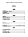
BEDIENUNGSANLEITUNG
USER'S MANUAL
MODE D'EMPLOI
MANUAL DEL USUARIO
PM-524
Pro-Mixer
© COPYRIGHT
Nachdruck verboten!
All rights reserved!
Réproduction interdite!
Prohibida toda reproducción!
Für weiteren Gebrauch aufbewahren!
Keep this manual for further needs!
Gardez ces instructions pour des utilisations ultérieurs!
Guarde este manual para posteriores usos.
Frontpanel
OMNITRONIC
MASTER LEVEL
L
– 20
2
1
12 V LAMP
MAX 120 mA
L
15
10
7
5
3
1
0
1
3
5
8+
R
R
3
CUE LEVEL
L+R
L+R
– 20
MIC 1
15
10
7
5
3
1
0
1
3
5
8+
POWER
GAIN
GAIN
ON
GAIN
OFF
MIN
Pro-Mixer
PM-524
MIN
MAX
CUE
MIX
CUE
SPLIT
MIN (KILL)
MAX (FX)
MIN (KILL)
MAX (FX)
-30 dB
MIN (FX)
+15 dB
MAX (FX)
MIN (KILL)
MAX (FX)
MIN (KILL)
MAX (FX)
10
CUE LEVEL
PHONO 1 LINE 1 MIC 1
MAX (FX)
+15 dB
MAX (FX)
MAX (FX)
10
L
R
0
10
BALANCE
BASS
-30 dB
MIN (FX)
PHONO 2 LINE 2 MIC 2
0
MIDDLE
MIN (KILL)
BASS
-30 dB
MIN (FX)
BOOTH
TREBLE
MIN (KILL)
MIDDLE
MIDDLE
BASS
0
MAX
TREBLE
TREBLE
TALKOVER
MIN
MAX
MASTER
+15 dB
MAX (FX)
PHONO 3 LINE 3 MIC 3
CH-1
CROSSFADER
ASSIGN
CH-1
HEADPHONES
10
CUE
CH-2
CH-2
10
10
CH-3
10
10
10
PGM
CUE
5
5
5
5
5
5
0
0
0
0
0
0
PGM
CUE MIXING
CUE
CUE
CUE
CH-1/CH-2
CH-3
10
5
0
0
5
10
BEAT
BEAT
CROSSFADER
Rearpanel
CAUTION
AC INPUT 115/230 V, 50/60 Hz
VOLTAGE
SELECTOR
115
Read manual before use.
To prevent electrical fire and shock hazard, do not expose this appliance
to moisture. Risk of electric shock! Do not open! Disconnect from mains
before changing fuse. Replace the fuse only with the same type and rating.
Vor Gebrauch Anleitung lesen.
Gerät vor Feuchtigkeit schützen. Bei Sicherungswechsel Netzstecker ziehen!
Gefahr! Gerät nicht öffnen! Nur Sicherungen mit gleichen Leistungswerten einsetzen.
Lire le mode d’emploi avant l’utilisation.
Afin de prévenir tous risques d’électrocution et de court-circuits, ne pas exposer
à l’humidité. Attention! Ne pas ouvrir le boîtier! Débrancher avant de remplacer le fusible.
Utiliser un fusible de rechange de même type.
Typ/Type: OMNITRONIC PM-524 EL
Spannungsversorgung/Power supply:
115/230 V AC, 50/60 Hz ~
L
Gesamtanschlusswert/Power
consumption: 30 W
Sicherung/Fuse: F 0,5 A, 250 V
230
MASTER
BOOTH
REC
LINE 3
OMNITRONIC
®
www.omnitronic.com
MIC 3
PHONO 3
LINE 2
MIC 2
PHONO 2
GND
LINE 1
PHONO 1
L
R
R
OMNITRONIC SHOWEQUIPMENT GmbH, GERMANY
OUTPUT
FUSE F 0.5 A, 250 V
CH-3
CH-2
CH-1
CUE
REV-
DIGITAL AUDIO
COMPACT
SHUTTLE/SCAN
FWD+
OMNITRONIC SHOWEQUIPMENT GmbH, GERMANY
R
OPEN/CLOSE
33
45
OUTPUT
BOOTH
LINE 3
0
7
3
REV-
COMPACT
SHUTTLE/SCAN
DIGITAL AUDIO
JOG/SEARCH
–
FWD+
2
1,0
1,5
2,0
ON
DD-3220
Professional High Torque Direct-Drive Turntable
OMNITRONIC
0,5
PITCH
+/-10 %
HEIGHT
PHONO 3
PITCH
+/-20 %
QUARTZ
LOCK
LINE 2
MIC 3
+
CH-2
PHONO 2
MIC 2
®
RELOOP
LOOP IN
OUT/EXIT
1 BIT 8 TIMES OVERSAMPLING D/A CONVERTER COMPACT DISC PLAYER
CUE
OPEN/CLOSE
2
OMNITRONIC
DISC 2
8
4
DISC 2
2
REMAIN
123456789
04 27:56:12
__
www.omnitronic.com
POWER
OPEN/CLOSE
OMNITRONIC
AUTO/NOR
RELAY
CH-3
1
Turntable 3
REC
6
9
5
DISC 1
2
1
DISC 1
OMNITRONIC
33
LINE 1
START/STOP
POWER
GND
45
CH-1
L
R
–
+
CUE
REV-
DIGITAL AUDIO
COMPACT
SHUTTLE/SCAN
FWD+
1,0
1,5
DD-3220
Professional High Torque Direct-Drive Turntable
OMNITRONIC
0,5
1
PITCH
+/-10 %
HEIGHT
PITCH
+/-20 %
REMAIN
QUARTZ
LOCK
OPEN/CLOSE
6
1
AUTO/NOR
RELAY
0
7
3
POWER
OPEN/CLOSE
OMNITRONIC
9
5
DISC 1
2
OMNITRONIC
1
DISC 1
123456789
0218:12:05
JOG/SEARCH
1
1 BIT 8 TIMES OVERSAMPLING D/A CONVERTER COMPACT DISC PLAYER
RELOOP
LOOP IN
OUT/EXIT
Turntable 2
PHONO 1
CDP-744
+12 %
+12 %
PITCH
0%
Dual CD-Player
CDP-744
–12 %
PITCH
TIME/
RANDOM
Dual CD-Player
0%
–12 %
TIME/
RANDOM
PITCH
PITCH
ON
START/STOP
POWER
MASTER
CAUTION
1
REMAIN
123456789
0218:12:05
JOG/SEARCH
1
Read manual before use.
To prevent electrical fire and shock hazard, do not expose this appliance
to moisture. Risk of electric shock! Do not open! Disconnect from mains
before changing fuse. Replace the fuse only with the same type and rating.
Vor Gebrauch Anleitung lesen.
Gerät vor Feuchtigkeit schützen. Bei Sicherungswechsel Netzstecker ziehen!
Gefahr! Gerät nicht öffnen! Nur Sicherungen mit gleichen Leistungswerten einsetzen.
Lire le mode d’emploi avant l’utilisation.
Afin de prévenir tous risques d’électrocution et de court-circuits, ne pas exposer
à l’humidité. Attention! Ne pas ouvrir le boîtier! Débrancher avant de remplacer le fusible.
Utiliser un fusible de rechange de même type.
Typ/Type: OMNITRONIC PM-524 EL
Spannungsversorgung/Power supply:
115/230 V AC, 50/60 Hz ~
L
Gesamtanschlusswert/Power
consumption: 30 W
Sicherung/Fuse: F 0,5 A, 250 V
FUSE F 0.5 A, 250 V
+
__
1 BIT 8 TIMES OVERSAMPLING D/A CONVERTER COMPACT DISC PLAYER
RELOOP
LOOP IN
_
OUT/EXIT
__
2,0
Tape Recorder, Cassette Deck, etc.
230
115
VOLTAGE
SELECTOR
AC INPUT 115/230 V, 50/60 Hz
PITCH
+12 %
0%
–
OFF
DISC 2
8
4
DISC 2
2
REMAIN
START/STOP
POWER
33
REV-
COMPACT
SHUTTLE/SCAN
DIGITAL AUDIO
JOG/SEARCH
2
–
FWD+
RELOOP
LOOP IN
OUT/EXIT
45
2
+
+12 %
0%
–12 %
TIME/
RANDOM
PITCH
PITCH
1,0
1,5
DD-3220
Professional High Torque Direct-Drive Turntable
OMNITRONIC
0,5
PITCH
+/-10 %
HEIGHT
PITCH
+/-20 %
QUARTZ
LOCK
Microphone 3
Microphone 2
Turntable 1
1 BIT 8 TIMES OVERSAMPLING D/A CONVERTER COMPACT DISC PLAYER
CUE
OPEN/CLOSE
123456789
04 27:56:12
CD-Player 1
ON
Speaker-system 2
Amplifier 2
Amplifier 1
OFF
Connect with mains
CDP-744
Dual CD-Player
CDP-744
–12 %
1
__
_
__
_
__
PITCH
TIME/
RANDOM
1
Dual CD-Player
0
__
OFF
_
CD-Player 2
0
_
_
__
_
1
_
Cassette Deck, DAT-Recorder, etc.
_
Speaker-system 1
_
_
0
_
2,0
MULTI-LANGUAGE-INSTRUCTIONS
Inhaltsverzeichnis
Table of contents
Sommaire
Contenido
EINFÜHRUNG ................................................................................................................................................... 5
SICHERHEITSHINWEISE ................................................................................................................................. 6
BESTIMMUNGSGEMÄSSE VERWENDUNG................................................................................................... 6
ANSCHLÜSSE .................................................................................................................................................. 7
GERÄTEÜBERSICHT ....................................................................................................................................... 9
PROBLEMBEHEBUNG................................................................................................................................... 12
REINIGUNG UND WARTUNG ........................................................................................................................ 12
TECHNISCHE DATEN .................................................................................................................................... 13
INTRODUCTION.............................................................................................................................................. 14
SAFETY INSTRUCTIONS............................................................................................................................... 15
OPERATING DETERMINATIONS .................................................................................................................. 15
CONNECTIONS............................................................................................................................................... 16
DESCRIPTION OF THE DEVICE.................................................................................................................... 18
PROBLEM CHART.......................................................................................................................................... 21
CLEANING AND MAINTENANCE.................................................................................................................. 21
TECHNICAL SPECIFICATIONS ..................................................................................................................... 22
INTRODUCTION.............................................................................................................................................. 23
INSTRUCTIONS DE SÉCURITÉ..................................................................................................................... 24
EMPLOI SELON LES PRESCRIPTIONS ....................................................................................................... 25
CONNEXIONS ................................................................................................................................................. 25
DESCRIPTION DE L'APPAREIL .................................................................................................................... 27
PROBLEM CHART...................................................................... FEHLER! TEXTMARKE NICHT DEFINIERT.
NETTOYAGE ET MAINTENANCE ................................................................................................................. 30
CARACTÉRISTIQUES TECHNIQUES ........................................................................................................... 31
INTRODUCCIÓN ............................................................................................................................................. 32
INSTRUCCIONES DE SEGURIDAD............................................................................................................... 33
INSTRUCCIONES DE MANEJO..................................................................................................................... 34
CONEXIONES ................................................................................................................................................. 34
VISTA GENERAL DEL APARATO................................................................................................................. 36
SOLUCIÓN DE PROBLEMAS ........................................................................................................................ 39
LIMPIEZA Y MANTENIMIENTO ..................................................................................................................... 39
ESPECIFICACIONES TÉCNICAS .................................................................................................................. 40
OPERATING INSTRUCTIONS
PM-524 Pro-Mixer
CAUTION!
Keep this device away from rain and moisture!
Unplug mains lead before opening the housing!
For your own safety, please read this user manual carefully
before you initial start-up.
All persons involved in the installation, operation and maintenance of this device have to:
- be qualified
- follow the instructions of this manual
INTRODUCTION
Thank you for having chosen a OMNITRONIC PM-524. If you follow the instructions given in this manual, we
can assure you that you will enjoy this device for many years.
Unpack your OMNITRONIC PM-524.
Please make sure that there are no obvious transport damages. Should you notice any damages on the A/C
connection cable or on the casing, do not take the device into operation and immediately consult your local
dealer.
Features
Professional 3-channel mixer
Channels 1-3 on the frontpanel switchable between phono, line or mic • Mic 1 microphone-input via
unbalanced XLR-socket on the frontpanel • Mic 2 and Mic 3 microphone-input via 1/4" mono-jack on the
rearpanel • Input-sensitivity-control (gain) for each channel • 3-fold, separate tone-control (bass, middle,
treble) for each channel with extremely wide range • Killfunction (attenuated to -30 dB) and F/X-function
(enforced to +15 dB) possible • High-quality and super-smooth ALPS-channel-faders • Super-smooth ALPScrossfader replaceable from above • Crossfader for mixing channel 1, 2 and 3 (Crossfader Assign-button) • 2
beat-indicators at the crossfader for perfect mixing • 3 LED-level-displays (master-out L/R and Cue Level) •
Headphones-connection on the frontpanel • Headphones-output adjustable via Cue Level-control • Additional
Cue Split/Cue Mix-button • Cue Split-function: the Cue-signal is on the one side of the headphones and the
output-signal on the other side • Cue Mix-function: the adjustable mix of Cue-signal and output-signal is on
both sides of the headphones • Mixing of the headphones-signal possible via cue mixing-fader • Output
signal adjustable via master-control and balance-control • Master-Out, Booth-Out and Rec-Out via 2 RCAsockets each • Rec-Out independent from Master-level for records with static level • Separately controllable
monitor-output (DJ-booth) for connecting active-speakers or an additional amplifier • High-grade multifunction-mixer with a convincing sound
The Kill-function makes it possible for you to cut the signal almost completely off by turning the control to the
left.
14
SAFETY INSTRUCTIONS
CAUTION!
Be careful with your operations. With a dangerous voltage you can suffer a dangerous
electric shock when touching the wires!
This device has left our premises in absolutely perfect condition. In order to maintain this condition and to
ensure a safe operation, it is absolutely necessary for the user to follow the safety instructions and warning
notes written in this user manual.
Important:
Damages caused by the disregard of this user manual are not subject to warranty. The dealer will
not accept liability for any resulting defects or problems.
Always plug in the power plug least. Make sure that the power-switch is set to OFF position before you
connect the device to the mains.
Keep away from heaters and other heating sources!
If the device has been exposed to drastic temperature fluctuation (e.g. after transportation), do not switch it
on immediately. The arising condensation water might damage your device. Leave the device switched off
until it has reached room temperature.
Never put any liquids on the device or close to it. Should any liquid enter the device nevertheless, disconnect
from mains immediately. Please let the device be checked by a qualified service technician before you
operate it again. Any damages caused by liquids having entered the device are not subject to warranty!
This device falls under protection-class II and features a protective insulation.
Never let the power-cord come into contact with other cables! Handle the power-cord and all connections
with the mains with particular caution!
Make sure that the available voltage is not higher than stated on the AC voltage selector.
Make sure that the power-cord is never crimped or damaged by sharp edges. Check the device and the
power-cord from time to time.
Always disconnect from the mains, when the device is not in use or before cleaning it. Only handle the
power-cord by the plug. Never pull out the plug by tugging the power-cord.
Before the device is switched on all faders and volume controls have to be set to "0" or "min" position.
CAUTION: Turn the amplifier on last and off first!
Keep away children and amateurs!
CAUTION: High volumes can cause hearing damage!
There are no serviceable parts inside the device. Maintenance and service operations are only to be carried
out by authorized dealers.
OPERATING DETERMINATIONS
This device is a professional audio-mixer for mixing audio-signals from different music-sources with one
another. This product is allowed to be operated with an alternating current of 115/230 V, 50/60 Hz and was
designed for indoor use only.
Do not shake the device. Avoid brute force when installing or operating the device.
15
When choosing the installation-spot, please make sure that the device is not exposed to extreme heat,
moisture or dust. There should not be any cables lying around. You endanger your own and the safety of
others!
Do not operate the device in extremely hot (more than 30° C) or extremely cold (less than 5° C)
surroundings. Keep away from direct insulation (particularly in cars) and heaters.
Operate the device only after having familiarized with its functions. Do not permit operation by persons not
qualified for operating the device. Most damages are the result of unprofessional operation!
Never use spray cleaners in order to clean the faders!
Never use solvents or aggressive detergents in order to clean the device! Rather use a soft and damp cloth.
Please use the original packaging if the device is to be transported.
Never remove the serial barcode from the device as this would make the guarantee void.
If this device will be operated in any way different to the one described in this manual, the product may suffer
damages and the guarantee becomes void. Furthermore, any other operation may lead to dangers like shortcircuit, burns, electric shock, etc.
CONNECTIONS
• Make sure that the power switch is set to "OFF". Before you connect the devices, all units have to be
switched off and the master-control is set to "0".
• Make sure that the available voltage is not higher than stated on the voltage selector before you connect
the power-cord.
• In order to obtain highest sound-quality, only use high-quality cables for connecting the devices. Make sure
that the cables are properly fixed.
• You can connect up to 2 amplifiers to the PM-524. The output signal of the Master-signal can be adjusted
via the Master-control and the Balance-control. The output-signal of the Booth-signal can be adjusted via the
Booth-control.
• The Master-output can be connected via the RCA-sockets. Make sure that the sockets are set properly
(L & R).
• Via the BOOTH sockets, you can either connect active monitor-speakers for the DJ-booth or an additional
amplifier for creating a second zone.
• For recording, connect your tape recorder or cassette deck to the REC OUT-sockets. The REC OUT level
will not be influenced by the master-control. You can set the output level with the channel faders, the tone
controls and the GAIN control.
•The MIC 1 microphone can be connected via the XLR mounting-socket on the frontpanel. With the
Talkover-button, you can attenuate the level of all other signal-sources without affecting the microphone
volume. You can adjust the microphone volume using the CH-1 fader. Make sure that the
PHONO/LINE/MIC-switch is set to MIC.
Occupation unbalanced XLR-socket:
Unbalanced XLR mounting-socket:
2
1
3
1: Ground
2: In Phase (+)
3: Ground
16
• Additionally, the PM-524 features two more ¼" MIC 2 and MIC 3 jack-sockets on the rearpanel. You can
adjust the microphone volume using the CH-2 and CH-3 fader. Make sure that the PHONO/LINE/MIC-switch
is set to MIC.
Occupation unbalanced mono-1/4“ jack-plug:
• You can connect up to 3 record players using the PHONO 1 sockets, PHONO 2 sockets and PHONO 3
sockets on the rearpanel. You can only control the record player signal after you switched the
PHONO/LINE/MIC switches to PHONO. The signal is then controlled via the CH-1, CH-2 and CH-3 faders.
• The short-circuit plug can only be plugged in unused Phono input-sockets in order to protect the input. This
plug must never be plugged into output-sockets or Line input-sockets.
• Connect your CD-player, DAT-recorder, cassette deck, tuner, tape recorder or all other line signals to the
LINE input-sockets on the rearpanel. You can only control the line signals after you switched the
PHONO/LINE/MIC switches to line. The signal is then controlled via the respective faders.
• Switch the device on. After switching on the amplifier, wait 8 to 10 seconds until you turn the volumecontrols in order to avoid speaker-damage.
• Under all circumstances avoid amplifier clipping. Distorted signals are the major cause of speaker-damage.
17
DESCRIPTION OF THE DEVICE
Frontpanel
OMNITRONIC
MASTER LEVEL
L
– 20
2
1
12 V LAMP
MAX 120 mA
L
15
10
7
5
3
1
0
1
3
5
8+
R
R
3
CUE LEVEL
L+R
L+R
– 20
MIC 1
15
10
7
5
3
1
0
1
3
5
8+
POWER
GAIN
GAIN
ON
GAIN
OFF
MIN
Pro-Mixer
PM-524
MIN
MAX
CUE
MIX
MIN (KILL)
CUE
SPLIT
MAX (FX)
MIN (KILL)
MAX (FX)
MAX (FX)
MIN (KILL)
MAX (FX)
0
-30 dB
MIN (FX)
10
CUE LEVEL
+15 dB
MAX (FX)
PHONO 1 LINE 1 MIC 1
MIN (KILL)
MAX (FX)
-30 dB
MIN (FX)
+15 dB
MAX (FX)
MIN (KILL)
MAX (FX)
CH-2
HEADPHONES
+15 dB
MAX (FX)
0
PHONO 3 LINE 3 MIC 3
10
CUE
10
CH-2
10
CH-3
10
10
10
PGM
CUE
5
5
5
5
5
5
0
0
0
0
0
0
PGM
CUE MIXING
CUE
CUE
CUE
CH-1/CH-2
CH-3
10
5
0
0
5
10
BEAT
BEAT
CROSSFADER
18
R
MASTER
ASSIGN
CH-1
BALANCE
L
CH-1
CROSSFADER
10
BASS
-30 dB
MIN (FX)
PHONO 2 LINE 2 MIC 2
0
MIDDLE
BASS
BASS
BOOTH
TREBLE
MIDDLE
MIDDLE
MIN (KILL)
MAX
TREBLE
TREBLE
TALKOVER
MIN
MAX
10
(1) 12 V LAMP
BNC-socket for gooseneck-lamp. The maximum current is 120 mA.
(2) POWER SWITCH with LED
Press this button to start operation. The Power-LED is illuminated when the mixer is ready for use.
(3) MASTER LEVEL / CUE LEVEL DISPLAY
The upper display shows the level of the left and right master output.
The lower display shows the level of the channel currently being cued (CUE LED on).
(4) GAIN-CONTROL
Used to set the level of the input signal.
(5) TREBLE-CONTROL
Used to increase or lower the HIs of the input signal.
(6) MIDDLE-CONTROL
Used to increase or lower the MIDs of the input signal.
(7) BASS-CONTROL
Used to increase or lower the LOWs of the input signal.
(8) PHONO/LINE/MIC-SWITCH
Used to select the input to be sent to the individual channel.
(9) CROSSFADER ASSIGN-BUTTON
Via this button you can select whether channel 1 (button pressed) or channel 2 (button released) will be
assigned to the left Crossfader-side. The other channel remains active.
(10)CHANNEL-FADER
Used to adjust the input level of each channel.
(11)CUE-BUTTON
Use the CUE-button in order to select the channel(s) to be monitored.
(12)BEAT-INDICATOR
The LED lights up at every bass-beat of the respective source. Ass soon as the LEDs flash synchronously, the speed of the two sources is synchronized.
(13)CROSSFADER
Mixes the signals of one channel with another. If the crossfader is in the center-position, both channels
can be heard.
(14)MIC 1-SOCKET
You can connect microphones with XLR-plug and control the signals via the Mic Level-control. You can
adjust the microphone volume using the CH-1 fader. Make sure that the PHONO/LINE/MIC-switch is set
to MIC.
(15)TALKOVER-BUTTON
Press this button if you want to use your microphone. When the button is pressed, all signals but the
microphone level are attenuated by 14 dB. In the OFF-position, all signals return to their original level.
(16)CUE SPLIT/CUE MIX BUTTON
Cue Split-function (button pressed and Cue Split-LED illuminated): the Cue-signal is on the one side of
the headphones and the output-signal on the other side.
Cue Mix-function (button released): the adjustable mix of Cue-signal and output-signal is on both sides
of the headphones.
(17)CUE LEVEL-CONTROL
With the CUE LEVEL-control, you can adjust the headphones volume without changing the output
signal.
(18)HEADPHONES SOCKET
With this socket, you can connect headphones with an impedance between 8 Ohms and 600 Ohms.
(19)CUE MIXING FADER
Connect your headphones to the HEADPHONES socket. With the CUE-buttons, you can select the
desired channel.
When you set the CUE MIXING-fader to PGM (CUE-buttons without function), you can cue the output
signal of the mixer.
When you set the CUE MIXING-fader to to the center position, you can cue both the channel-signal you
selected and the output-signal.
(20)BOOTH-CONTROL
The PM-524 features a DJ BOOTH monitor system. Connect your monitor system with the BOOTHsockets on the rearpanel.
(21)BALANCE-CONTROL
Used to adjust how much of the signal is sent to the left and right MASTER-socket.
(22)MASTER-CONTROL
Adjusts the level of the MASTER-output.
19
Rearpanel
CAUTION
AC INPUT 115/230 V, 50/60 Hz
VOLTAGE
SELECTOR
115
Read manual before use.
To prevent electrical fire and shock hazard, do not expose this appliance
to moisture. Risk of electric shock! Do not open! Disconnect from mains
before changing fuse. Replace the fuse only with the same type and rating.
Vor Gebrauch Anleitung lesen.
Gerät vor Feuchtigkeit schützen. Vor Sicherungswechsel vom Netz trennen!
Gefahr! Gerät nicht öffnen! Nur Sicherungen mit gleichen Leistungswerten einsetzen.
Lire le mode d’emploi avant l’utilisation.
Afin de prévenir tous risques d’électrocution et de court-circuits, ne pas exposer
à l’humidité. Attention! Ne pas ouvrir le boîtier! Débrancher avant de remplacer le fusible.
Utiliser un fusible de rechange de même type.
Typ/Type: OMNITRONIC PM-524
Spannungsversorgung/Power supply:
115/230 V AC, 50/60 Hz ~
L
Gesamtanschlusswert/Power
consumption: 30 W
Sicherung/Fuse: F 0,5 A, 250 V
230
MASTER
BOOTH
REC
LINE 3
OMNITRONIC
®
www.omnitronic.com
MIC 3
PHONO 3
LINE 2
MIC 2
PHONO 2
GND
LINE 1
PHONO 1
L
R
R
OMNITRONIC SHOWEQUIPMENT GmbH, GERMANY
OUTPUT
CH-3
CH-2
CH-1
FUSE F 0.5 A, 250 V
(23) GND (Ground terminal)
Connect the ground lead of the turntable with this terminal. This helps to reduce humming and pop noise.
(24) MIC 2-SOCKET
Connect your microphone with ¼" jack plug here. The signals can be controlled via CH-2, if the PHONO 2 /
LINE 2 / MIC 2-switch is set to MIC 2.
(25) MIC 3-SOCKET
Connect your microphone with ¼" jack plug here. The signals can be controlled via CH-3, if the PHONO 3 /
LINE 3 / MIC 3-switch is set to MIC 3.
(26), (27), (28) LINE / PHONO INPUT-SOCKETS
Input socket for CH-1, CH-2 and CH-3. Connect your turntable(s) with the PHONO input-sockets. CD-players
or Tape Decks should be connected with the LINE input-sockets. Line level musical instruments with stereo
outputs such as Rhythm Machines or Samplers should also be connected with the LINE input-sockets.
(29) REC OUT
To connect your recording unit. The REC OUT-level is not influenced by the Master-control.
(30) BOOTH
Connect your monitor system here.
(31) MASTER OUT
Output sockets for connecting your power amplifier.
(32) FUSEHOLDER
Only replace the fuse when the device is disconnected from mains. Only use fuses of the same rating and
power.
(33) AC-CONNECTION
Used to plug the power-cord in.
(34) AC VOLTAGE-SELECTOR
Make sure that the selector is properly set.
20
PROBLEM CHART
PROBLEM:
No power.
CAUSE:
• The power-cord is not connected.
No sound.
• The PHONO/LINE/MIC-switch of the
respective channel is in the wrong
position.
• The power-cord of the respective
device is not connected properly or
not connected at all.
• The connection-socket or the plug is
dirty.
• The input-signal is too strong.
Noise.
No crossfader.
• The crossfader was not assigned
properly.
REMEDY:
• Check the power-cord and any
extension-cables.
• Put the PHONO/LINE/MIC-switch
into the correct position.
• Check the power-cord and if the
plugs are tightly connected with the
sockets.
• Clean the socket and/or the plug.
• Reduce the input-signal via the Gaincontrol.
• Assign the desired channel to the
crossfader via the Crossfader Assignbutton.
CLEANING AND MAINTENANCE
DANGER TO LIFE!
Disconnect from mains before starting maintenance operation!
We recommend a frequent cleaning of the device. Please use a soft lint-free and moistened cloth. Never use
alcohol or solvents!
There are no servicable parts inside the device except for the fuse. Maintenance and service operations are
only to be carried out by authorized dealers.
Should you need any spare parts, please use genuine parts.
If the power supply cable of this device will be damaged, it has to be replaced by a special power supply
cable available at your dealer.
Should you have further questions, please contact your dealer.
Replacing the fuse
If the fine-wire fuse of the device fuses, only replace the fuse by a fuse of same type and rating.
Please note: This fuse is being used for both 115 V and 230 V.
Before replacing the fuse, unplug mains lead.
Procedure:
Step 1: Unscrew the fuseholder on the rearpanel with a fitting screwdriver from the housing (anticlockwise).
Step 2: Remove the old fuse from the fuseholder.
Step 3: Install the new fuse in the fuseholder.
Step 4: Replace the fuseholder in the housing and fix it.
21
Replacing the Crossfader
Instructions for replacing the crossfader:
• Remove the fader knob.
• Remove the two outer screws on the fader-panel.
• Take the fader out and unplug the connection-cable.
• Connect the new fader and fix it in the device.
The fader-panel of the replacement-crossfader cannot be used for the Design-version. In order to exchange
the fader-panels, additionally unscrew the 2 inner screws and exchange the two fader-panels.
TECHNICAL SPECIFICATIONS
Power supply:
Power consumption:
Inputs:
Minimum input voltage:
Microphone:
Phono:
Line:
Output voltage:
Line:
Headphones:
Outputs:
Frequency range:
Microphone:
Phono:
Line:
Distortion:
S/N-ratio:
Microphone:
Phono:
Line:
Talkover-attenuation:
Tone control:
Treble:
Middle:
Bass:
Dimensions (WxDxH):
Weight:
Replacement crossfader:
115/230 V AC, 50/60 Hz ~
30 W
3 phono, 3 line, 3 mic
3 mV RMS, 2.2 kOhms
3.2 mV RMS, 47 kOhms
150 mV RMS, 4.7 kOhms
7 V RMS max.
0.4 V
1 Master-Out, 1 Rec-Out, 1 Booth-Out via RCA
20 - 20,000 Hz, ± 3 dB
20 - 20,000 Hz, ± 3 dB
10 - 50,000 Hz, ± 3 dB
< 0.05 %
-60 dB
-50 dB
-64 dB
-14 dB
10 Khz -30 dB to +15 dB
1 KHz -30 dB to +15 dB
100 Hz -30 dB to +15 dB
254 x 320 x 99 mm
3.5 kg
No. 10007190
Please note: Every information is subject to change without prior notice. 02/01 ©
22