1
K. U. LEUVEN
DEPARTMENT OF APPLIED ECONOMIC SCIENCES
PROcedural LOGic Analyzer 5.2
USER'S MANUAL
© J. Vanthienen, 2003
1. Introduction
1.1.
About Prologa
The Prologa (PROcedural LOGic Analyzer) system is an interactive design tool for computersupported construction and manipulation of decision tables.
The system not only supports the manual design techniques, but also offers additional features to
enhance the construction, manipulation and validation of decision tables.
Other tools for the construction of decision tables are usually column oriented. They allow the
user to generate an empty decision table and then to fill in the columns one by one. These systems
may ensure/check for combinatorial completeness, consistency and/or non-redundancy, but offer
little or no help in the design process itself. Prologa, being rule based, does not bear these
inadequacies.
The Prologa software is written in Borland Delphi and runs on Windows 98, NT, 2000 and XP.
Version 5 adds the following features to the previous versions:
•
•
•
•
•
Totally redesigned user interface;
Import from Microsoft Excel;
Improved database functionality;
Intelligent project editing;
Fuzzy decision tables.
Prologa User's Manual
-2-
1. Introduction
New in 5.2:
•
•
Improved consultation environment
Dockable windows have been included in the consultation environment,
to improve its customizability. Also, parts of the original engine have
been redesigned internally;
XML Import/export
We have provided an XML-format for Prologa decision tables:
one can now import a table from or export it to this new file format.
(see http://www.econ.kuleuven.ac.be/tew/academic/infosys/research/prologa/decisiontable.xsd)
New in 5.1:
• New and improved export functions:
Prologa now also supports code generation to Java, C and Eiffel. Also, a prototype
version is included that allows you to export a decision table into an MS Word table;
• View as Tree:
One can now view decision tables in a hierarchical tree format (use the upper left button in
the decision table editor window).
Previous versions of the Prologa software include:
v. 1.0 : DOS-version
v. 2.0 : DOS-version, extended user interface
v. 3.0 : Windows 3.x version
v. 4.0 : Windows 95 & NT version
1.2.
Application Experiences
The decision table workbench Prologa has been used in a large number of applications and
environments. Some examples of the more common areas of experience:
-
verification and visualization of legal procedures;
checking consistency in medical treatments;
help desk applications for computer networks;
validation of knowledge based systems;
modeling and verification of complex procedural decision situations in general;
information systems analysis, descriptions of systems requirements and software
engineering;
rates and premiums in banks, insurance companies;
checking technical specifications in manufacturing;
generating test cases for program structures.
Besides the classical arguments for the use of decision tables (easy checking for completeness,
consistency and correctness), a number of less known advantages have been revealed by these
experiences: good communication facilities with the end user, full life cycle support,
implementation independence, ease of translation, ... .
Prologa User's Manual
-3-
1. Introduction
1.3.
Using this manual
This manual has been written for both users experienced with the practice of decision tables and
novices to the topic. Therefore, this manual will not only explain Prologa, but will also deal with
the theory of building decision tables and with the way to represent the gathered knowledge.
This manual is split into 3 parts:
The first part explains the Prologa system and shows examples of a Prologa session.
The second part will treat the concept of decision tables and the description of the knowledge
specification language for decision tables. The emphasis will be on the differences between the
conventional view on decision tables and the form that is adopted here.
Finally the third part consists of a reference manual which deals with various commands,
shortcuts, limitations and hints and the relations between the different export facilities and other
systems.
Prologa User's Manual
-4-
1. Introduction
2. The Prologa
System
This chapter is the core of the User's guide. It explains most of the functions of Prologa and
shows when to use them. It also shows the advantages and limitations of the system, and explains
what a Prologa session should look like.
2.1.
A Short Introduction to Decision Tables
Even if at first sight decision tables in their current form look almost the same as years ago, their
use has changed a lot. A decision table is a tabular representation of a decision situation, where
the state of a number of conditions determines the execution of a set of actions. Not just any
representation, however, but one in which all distinct situations are shown as columns in a table,
such that every possible case is included in one and only one column (completeness and
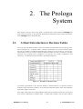
exclusivity). An example of a decision table is presented in Figure 2-1.
Figure 2-1. Example of a Decision Table
The tabular representation of the decision situation is characterized by the separation between
conditions (top) and actions (bottom), on one hand, and between subjects (left) and conditional
expressions (right), on the other.
Every table column (decision column) indicates which actions should (or should not) be executed
for a specific combination of condition states. A column then contains a state for each condition
Prologa User's Manual
-5-
2. The Prologa System
or a contraction of states which yield the same result (with possibly "irrelevant" ("-") if this is the
case for all states of that condition), followed by the resulting value for each action. The condition
oriented approach of the decision table makes it very useful to display knowledge, with such
advantages as : overview, readability, easy checking for consistency and completeness.
The order of the columns shows that only single hit tables are taken into account, in other words,
each situation is present in only one column and, consequently, the columns will not interfere with
each other. This excludes the use of the so called multiple hit tables, where a particular situation
can be present in several (partially overlapping) columns, such that the order of the columns
determines the decision logic, which strongly reduces the overview and the validation possibilities.
If each column only contains simple states (no contractions or irrelevant conditions), the table is
called an expanded decision table (canonical form), in the other case the table is called a
contracted decision table (consolidated form). The transition from one form to the other is defined
as expansion (rule expansion) and contraction (consolidation).
2.2.
Getting Started with Prologa
The construction of decision tables is a creative activity but it contains several routine actions
which are quite time-consuming. This chapter deals with automating the construction of decision
tables, which will be discussed in detail.
2.2.1.
A Guide through Prologa
Decision tables in Prologa are organized in projects. A project contains one or more (possibly
related) decision tables and supplementary information about the tables. The project information
is stored in a relational database (ProjectName.MDB) and in a number of decision table files
(DecisionTableName.TAB).
Although it is possible in Prologa to create and edit tables without using a project (for
historical reasons), this is not recommended, as a lot of manipulations are only available at
the project level, not at the table level.
When building each individual decision table, the user should essentially provide the system with
the following information : a list of conditions with their states, a list of actions and a list of
relations between condition states and actions (in the form of logical expressions or rules). This
enables the system to construct and display the corresponding decision table.
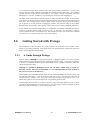
Constructing a decision table is an iterative process, where the ability should be given to make
corrections and refinements in an interactive way. For this purpose a flexible dialogue structure
has been provided, containing a.o. the following major steps:
Prologa User's Manual
-6-
2. The Prologa System
Create or Open a decision table project
¦
Create or Open a decision table
¦
Create or Edit actions, conditions and condition states
Create or Edit Decision Rules
¦
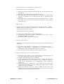
Check for completeness, correctness and consistency in
or between tables
¦
Convert or Use the decision tables
Figure 2-2. Major steps in Prologa
2.2.2.
Basic Functions of the Prologa system
In this section, we will start by explaining each basic function. In another chapter you will find
complete examples of the underlying Knowledge Acquisition, Knowledge Structuring and
Validation cycle.
2.2.2.1.
Create or Open Project
Select the File menu and choose New Project or Open Project. As a project will contain a number
of related files, it is good practice to use a specific (new) folder for every project.
Create New Project
A project is a collection or knowledge base of related decision tables. For each project, there is an
MS Access database file into which all kinds of information is stored. For instance, information
about prompts, help notes, etc. that is used for consultation purposes is stored here.
Why use projects and not just work with separate tables?
• file management is handled by Prologa
• the consultation environment only works with projects
• additional functionality is available in projects, such as intertabular verification, direct
linking between tables and automatic updating.
Prologa User's Manual
-7-
2. The Prologa System
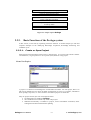
Open Existing Project
Choose e.g. the orders example from the distribution disk and select the project (orders.prj). The
project window appears, showing the relation between tables in the project. Double-click a table
to open it.
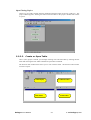
2.2.2.2.
Create or Open Table
Once a (new) project is started, you can begin working with a decision table by selecting the File
menu and choosing the New Table command or Open Table command.
The decision table window then allows you to work with this table. The decision table window
consists of 4 parts:
Table Display
Condition Editor
Rule Editor
Prologa User's Manual
Action Editor
-8-
2. The Prologa System
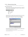
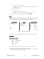
2.2.2.3.
Editing the Decision Table
The decision table is specified using conditions and condition states, actions and decision rules.
Editing conditions and actions
Conditions and actions constitute the major elements of the decision table. The number of
conditions, condition states and actions that can be entered is limited. If there is a need for more
conditions or actions, it is usually an indication that the problem is too complex to model in one
single table and table structures might be useful.
edit
accept
delete
add
Conditions and actions can be added (plus button), removed (minus button) edited (edit button),
reordered (drag & drop a condition to its new position in the list or in the decision table).
Conditions and actions can only be removed if they are not used in a decision rule.
Names (e.g. of conditions, condition states or actions) are not case-sensitive in Prologa.
Condition subjects (e.g. color) and states (e.g. red, blue, etc.) are entered in a separate form.
A total of 9 conditions can be entered, with a maximum of 9 states for each condition. Due to
memory limitations, the total number of state combinations, which is equal to the maximal number
of columns of the expanded decision table, is limited to 4096.
Actions can be edited directly on the action grid (press enter or ü-button to end editing state).
A total of 20 actions can be entered.
Prologa User's Manual
-9-
2. The Prologa System
edit
accept
delete
add
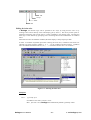
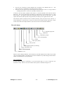
Editing decision rules
In Prologa, the decision logic can be specified in two ways: by using decision rules or by
clicking action entries directly in the table display (fill by mouse). The fill by mouse option is
meant for fine-tuning, but in most cases it is more rewarding to use decision rules. The decision
table logic is then entered by specifying rules connecting actions and combinations of condition
states.
When decision rules are added or modified, the table display is always kept up-to-date.
In order to minimize keyboard input when entering decision rules, conditions and actions are
referred to by their sequence number (1, 2, 3, …) in the condition and action editor. Condition
states are indicated with their letters (a, b, c, …). 1a therefore means state a of condition 1.
Figure 2-3. Entering decision rules
Examples:
rule 1 : 1 generally if 1a
If condition 1 has state a, action 1 is true.
Hint : just enter 1 if 1a, Prologa will automatically add the "generally" token.
Prologa User's Manual
- 10 -
2. The Prologa System
rule 2 : Not 1 generally if 1a and (2b or 3acd)
If condition 1 has state a, and condition 2 has state b or condition 3 has state a, c or d,
then action 1 is false.
(partially overrides rule 1)
rule 3 : Not 1 definitely if 1b
If condition 1 has state b, action 1 is false.
("definitely" means that the entries cannot be overridden by another rule)
For some other constructs, look at the example tables shipped with Prologa.
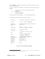
Syntax:
A decision rule consists of an action-part, an if-part and a condition-part, in this order. In the
following table, the syntax is split in three parts, each part is represented in a column. The
operators (with their internal notation) are listed in descending order of priority.
ACTION PART
Impossible
all
IF PART
:/
:@
1. dif (definitely if) : !
2. if (generally if) : :
3. pif (possibly if) : ?
1..9
1. not
2. and
2. only
CONDITION PART
always : #
0..9
a..f
rule : .
::*
:|
1. ( )
2. not
3. and
minus
nand
4. or
xor
nor
5. only
::*
:\
:$
:+
:&
:%
:|
Figure 2-4. Elements of a decision rule
The complete decision table language behind this syntax, is described elsewhere in the manual.
Brief overview:
optimize
accept
delete
add
Rules can be edited directly on the rules grid. Rules can be reordered using drag & drop.
There are three types of decision rules (with corresponding table entries):
1. Definite rules: can not be overwritten. Trying to overwrite a definite entry with an opposite
definite entry will trigger a contradiction warning;
Prologa User's Manual
- 11 -
2. The Prologa System
2.
3.
General rules: allowing to specify default rules, exceptions to the default rules, a.s.o. The
order of the rules is important as overriding entries is possible.
Possible rules: this type is only used to express rules of the form: action x is only possible if
…, meaning that action x is not to be executed in all other cases.
A button in the rule editor (optimize rules) allows to recreate (minimal) rules from the current
table logic. This can be interesting if the table was created using a lot of simple rules (e.g. using
fill by mouse). The optimize rules option basically produces one rule for each action. Use this
option with caution (and only after saving the table) as it destroys the original decision rules.
Note that the number of decision rules is limited (currently, about 126 rules can be entered). A
second limitation is that the rules, as they are stored in the internal decision grid chart, cannot
contain more than 1024 simple elements. (See also the section on Limitations & Hints.)
The table display
Edit table properties
Modularize
Dependency Graph
Save (isolated table)
Export
V&V report (table)
Fill by mouse
Optimize table by reordering
Expanded mode
Contracted mode
Table/tree view
While (or after) editing conditions, actions and rules, the table display always offers an up-to-date
view on the decision table. The table can be shown in different ways and starting from the table a
number of manipulations can be performed.
View as table/tree
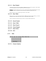
In some cases it might be interesting to view the decision table as a tree (or export the tree
structure to a file). The tree view also contains some options as indicated in Figure 2-5.
Prologa User's Manual
- 12 -
2. The Prologa System
Figure 2-5. View table as tree
Selecting the appropriate Table View
By default the contracted table is shown, because it is more compact. For validation or fill by
mouse purposes, it might be interesting to temporarily switch to the expanded table view.
The number of columns in a decision table, however, can not only be reduced by contracting the
table. The order in which the conditions appear in the decision table may have a strong influence
on the number of columns the contracted table will contain. Prologa can help you to set the
optimal order of these conditions such that the size of the decision table will be reduced to a
minimum. Impossible condition orders can be excluded from the evaluation by imposing
precedence constraints. When you activate Optimize Order, all possible orders will be evaluated.
You can then choose one of the suggested condition orders.
The first step is to calculate the number of feasible condition orders. This number will depend on
the number of conditions and the restrictions on their order (sometimes condition X has to be
tested before condition Y). The second step Prologa will take is the generation of all feasible
orders (list of feasible condition orders) where the order resulting in the smallest number of
columns will be retained.
Fill table by mouse
By setting a table into "fill table" mode, one can fill in individual table entries by mouse in order to
complete or adjust the table.
Clicking on a '.' or '-' produces a 'x', while clicking on a 'x' reverses it into a '-'. Every update leads
to a 'generally if' decision rule which is added automatically. Definite entries cannot be changed
because of their higher priority and because overriding is not allowed.
Switch off the “fill table” mode after editing in order to update the table display. While “fill table”
mode is on, some table operations are not possible before it is switched off again.
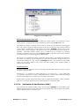
2.2.2.4.
Validation & Verification (V&V)
Two verification & validation (V&V) reports are provided in Prologa: the (intra)tabular report
indicates problems within a single table, while the intertabular V&V report analyzes the relations
between different tables in the same project.
Prologa User's Manual
- 13 -
2. The Prologa System
Figure 2-6. IntraTabular V&V report
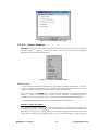
2.2.2.5.
Export Options
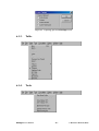
Prologa can generate various other representations, that can then be saved as a text file, copied to
the clipboard, etc. . Figure 2-7 provides you with an overview of the commands in the Export
Submenu and the export files they generate.
Figure 2-7. Export Commands & Files
Generate Code
In some cases decision tables are designed to be converted to executable program code. The code
can be a straightforward translation of the columns of the (contracted) decision table, or it can be
optimized for execution efficiency by generating the optimal execution tree.
When generating code, Prologa will start from the contracted table. All non-positive action
entries ('-', '.' and '?') are converted into '-' (do not execute). Subtables are indicated, but are not
included in the code. The resulting code is represented as a nested IF THEN ELSE statement.
A straightforward translation is provided for common programming languages.
PASCAL, C, JAVA, Visual Basic, …
The generated program code will only give the structure of the resulting if-then-else-statement
(according to the syntax of the language). To obtain executable program code, I/O-statements and
declarations will have to be added. Moreover, the names of conditions, condition states and
actions must correspond to the language syntax. Even if the decision table is simply converted
Prologa User's Manual
- 14 -
2. The Prologa System
from left to right and from top to bottom into nested if-then-else structures (without further
optimization), usability of code is quite high, as minimal execution time is not always the most
important issue.
COBOL
COBOL code can be generated in two ways: as if-then-else-statements or using the EVALUATE
statement.
The EVALUATE statement, as it was defined in ISO COBOL 85, is an attempt to include decision
tables in COBOL. When generated from Prologa, it is much easier to construct the statement.
The generated code is a straightforward left to right translation of the decision table (with one
WHEN clause for each table column).
Optimal Code
A lot of research on decision tables has been about generating optimal programs, taking into
consideration condition test times and column frequencies. This means that in different paths of
the execution tree, conditions are not necessarily tested in the same order. In each branch of the
tree, the most decisive condition will be examined first, thereby minimizing execution time of the
decision process.
The problem of optimal conversion is not treated extensively in Prologa, as it was not meant for
programming purposes in the first place. What Prologa can do, however, is generate a (near)
optimal execution tree in the same common programming languages. Condition test times and
column frequencies are considered equal. Precedence constraints between conditions are not taken
into account.
Generate Decision table Statement
The decision table statement is a short notation containing all elements of the decision table
(conditions, actions and rules), much like the Prologa table file, but without the internal data
structures.
Example:
DECTABLE
COND 1: Age Of Account : < 1 Year, >= 1 Year;
2: Annual Amount (T) : < 1, >= 1 - < 5, >= 5;
ACT 1: Customer := Not Good;
2: Customer := Good;
RULES 1: Only 2 generally if 1a and 2bc or 1b and 2c;
2: Only 1 generally if not rule 1;
3: 2 generally if always
END
Generate MS-Word Table
The decision table can be exported to an MS-Word table, such that the table elements can easily be
manipulated in MS-Word.
Prologa User's Manual
- 15 -
2. The Prologa System
Decide on Order
1. Credit Limit
2. Customer
3. Stock Sufficient
1. ^Execute Order
2. Refuse Order
3. Put on Waiting List
Ok
Y
x
1
N
x
2
Good
Y
N
x
x
3
4
Not Ok
Not Good
x
5
Figure 2-8. Export to MS-Word
2.3.
Advanced features of Prologa
Prologa has been built as a full decision table engineering workbench, incorporating several
possibilities of decision tables. It has advanced features going much further than the automated
design of single decision tables. This section explains the working of those features. Examples
are given in other chapters.
Some of the features go well beyond simple editing and might involve complex changes in the
decision table project or tables. It might be a good idea to save first, in case you are not satisfied
with the result and want to undo the entire operation.
2.3.1.
Projects and Relations between decision tables
A table can refer to one or more subtables. Subtables can be referred to by multiple tables.
Two kinds of subtables are possible:
• Action subtables will give further details on what additional knowledge holds for certain
cases, e.g. what discount to give if an order is accepted (similar to a procedure in a
programming language);
• Condition subtables will determine the state of a certain condition, e.g. when do you
consider someone a good customer? (comparable to a function in a programming
language).
All subtables are closed tables that will return to the place they were activated from (no goto's).
Therefore the actions or conditions that are below a subtable call will be executed as well (after
executing the subtable).
2.3.1.1.
Linking project tables
Relations between tables and subtables are maintained by the project and visualized in the Project
Net.
Using a project offers a lot of advantages for linking tables:
• Relations are based on logical table names (for action subtables) and subject names (for
condition subtables), as specified in the project;
• The Project Net window is automatically updated;
• If there is no decision table in the project with that specific name, a new table will be
automatically created and linked;
Prologa User's Manual
- 16 -
2. The Prologa System
•
The Consultation environment and Intertabular verification only work with projects, not
single tables.
Relations with subtables are created by starting the condition or action name with ‘^’.
Example:
Assume that ‘Decide on Order’, ‘Evaluate Customer’ and ‘Execute Order’ are three tables in an
‘Orders’ Project.
The ‘Decide on Order’ table contains a condition ‘^Customer’, which will receive its value in
another table. This other table can have any name, as long as at least some of its action subjects
read Customer := Good, or some other value.
The ‘Decide on Order’ table also contains an action ‘^Execute Order’, which refers to the name of
an action subtable.
2.3.1.2.
Direct linking of tables without a project
In the current Prologa version, there is a way of specifying relations between single tables that
do not belong to a project.
This facility only exists for historical compatibility reasons and it is not recommended for new
developments, as there are a number of limitations:
• Relations are based on filenames of tables, not subjects or logical names;
• All tables should be in the same directory;
• The structure depicted in the table net window is not automatically updated when changes
are made to the structure (tables should be saved first, and the net must be reopened);
• The Consultation environment and Intertabular verification only work with projects, not
single tables.
Example:
Assume that ‘ORDERS’, ‘CUSTOMER’ and ‘EXECUTE’ are three tables in an Orders Problem.
The ‘ORDERS’ table contains a condition ‘^Customer’, which will receive its value in the
‘CUSTOMER’ table. This table needs to have same filename as the condition and at least some of
its action subjects should read Customer := Good, or some other value.
The ‘ORDERS’ table also contains an action ‘^EXECUTE’, which refers to the filename of an
action subtable.
2.3.1.3.
Structure of a Prologa Project
A Prologa project is more than a simple collection of decision tables. From version 5.0 on,
additional behavior has been stored in the project, making it easier to use and edit.
When a new condition or action is created in Prologa, the project component will automatically
create a decision attribute or a subtable reference. These intelligent links are then maintained by
the project with the following advantages:
•
•
•
Faster navigation through the project, resulting in decreased execution times.
Intelligent updates of all referenced conditions and actions.
Intelligent value-editing (future versions).
Decision attributes
Many projects have recurring conditions, have actions that refer to other tables, or have actions
that set the value of another table's condition. Sometimes the same condition occurs, but with
different states.
Prologa User's Manual
- 17 -
2. The Prologa System
It is clear, however, that these actions and conditions are related to a single piece of information,
namely a decision attribute. Prologa maintains these decision attributes automatically and
transparently. If a user enters, edits or deletes conditions or actions, the decision attributes are
updated as well.
For example, when a new condition is added to a decision table, Prologa will look for an
decision attribute that matches the condition name. If this decision attribute has been found,
Prologa will automatically create a link to that decision attribute. If the decision attribute has not
been found, a new one will be created.
The same goes for actions. Actions of the type 'Customer := Good' refer to the decision attribute
named Customer.
Intelligent Linking
A project decision table now has some additional functionality compared to decision tables in
earlier versions. This functionality reflects the inter-tabular relationships of the project, as well as
the additional functionality stored with the conditions, condition states and actions.
For example, when entering the action '^SubTable', a reference to the table named '^SubTable' is
automatically created. If there is no table with that name, a new table will be created
automatically. If a table is deleted, but still has actions referring to it, these actions will be
converted into simple actions, decision attributes will be created for these actions etc.
Advantages of decision attributes and intelligent linking in Prologa projects:
There are two main advantages to the use of decision attributes and intelligent linking.
First of all, if the name of a condition, action or table changes, and there are other references to
the same decision attribute or table, the user has a choice to either:
•
•
Cascade the change over the entire project. For example, if two conditions refer to the
same decision attribute, and if the user changes the name of one of the conditions, the
other condition's name will be updated automatically.
Only change the current object. This will create a new decision attribute or table, and the
changed object will be disconnected from the previous decision attribute or table.
The second advantage is faster navigation through the project. For example, when starting a
consultation session, Prologa will automatically determine the main table of your project, using
the information contained in conditions and actions.
2.3.2.
Composition and Decomposition of Decision Tables
Prologa allows to move conditions or actions between tables, including the corresponding
decision logic:
• Move conditions/actions including the decision logic from one table to another (using
drag & drop);
• Join two tables into one (using drag & drop of the lower left part of a table into another);
• Decompose a table into separate tables, either independent or containing repetitions,
using the Modularize option.
Prologa User's Manual
- 18 -
2. The Prologa System
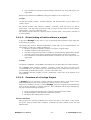
Figure 2-9. Modularization of a decision table
2.3.3.
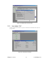
Intertabular V&V
Possible anomalies between tables in a project are examined in the intertabular V&V option (see
the Tools Menu).
Figure 2-10. Intertabular V&V Report
Prologa User's Manual
- 19 -
2. The Prologa System
2.3.4.
Consultation of a Decision Table Project
Prologa enables the consultation of the decision tables in a project. During a consultation
session, the system will inquire about the condition states of each relevant condition in the
appropriate tables and, at the end, will present a list of actions to be taken.
The user is asked to select the appropriate condition states to find a unique column in the decision
table (or all relevant decision tables). Only conditions relevant to the specific situation are
presented, in the order in which they are included in the decision tables. As soon as such a unique
column is discovered, the relevant actions are shown to the user.
It is also possible for a condition or action to call subtables. The process of switching from one
table to another in a hierarchy of decision tables is performed entirely by the system and is
transparent to the user. He does not (have to) know the exact structure of the application.
It goes without saying that this could easily be done manually for a single table, but in case the
project contains several subtables, the advantages of the automated consultation system become
clear. The subtables will be activated automatically, and when they are processed, the system will
return to the place in the higher table from where the subtable was called. In this way a complete
decision situation can be consulted via question and answer.
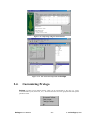
Figure 2-11. Consultation Environment
The decision table consultation environment also offers extensive consultation facilities which
help the user to navigate through the application and find the right action(s): explanation, specific
help, multimedia support, selective restart, case archivation, … .
For instance, there exists an option to change an answer that was previously entered (all other
selections remaining equal) or to restart decision making. Together with the case archivation
option this enables one to perform 'what-if' analyses or to use standard cases.
Prologa User's Manual
- 20 -
2. The Prologa System
2.3.5.
Import from Excel
Prologa allows to import a decision table which is specified in an Excel spreadsheet (use the
Tools menu). The spreadsheet contains a list of conditions with their states, a list of actions, a list
of decision rules and a list of impossibilities. A wizard will guide the flexible import process.
Take a look at the example spreadsheet on the distribution disk using the import wizard.
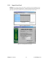
Figure 2-12. Import from Excel
Figure 2-13. Selecting the Excel Workbook
Prologa User's Manual
- 21 -
2. The Prologa System
Figure 2-14. Importing using the Excel Wizard
Figure 2-15. The Excel table imported into Prologa
2.4.
Customizing Prologa
Prologa provides several default settings which can be customized by the user (e.g. colors,
screen and table layout, directories, etc.). All these functions have been grouped under the Options
pull-down menu.
Prologa User's Manual
- 22 -
2. The Prologa System
Options can be customized to your own preferences and will then be valid for all following
sessions. These preferences are stored in the PROLOGA.INI file.
If you have changed some settings and you want to return to the Prologa default settings, use the
default button in the options menu.
2.4.1.
Environment Settings
These settings allow you to change the directories where Prologa will look for projects or tables
or where the various export-formats will be written.
Project Directory
The Projects directory is the default directory to store Prologa projects (default:
Prologa\Projects). Projects will normally constitute a specific subdirectory.
Table Directory
The directory for single tables (no projects) is the Table Directory (default: Prologa\Tables).
Log Directory
Several Export possibilities are provided in Prologa. These commands will write to the Log
Directory (default: Prologa\Log).
If you want your export files in the same directory as the original project, the log directory should
be equal to the project directory.
2.4.2.
Table Settings
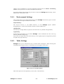
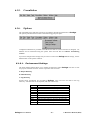
Prologa allows you to customize the way a decision table is displayed. When selecting this
command from the Options menu, a second menu level will appear on the screen.
Figure 2-16. List of Table Options
Most of the options are self-explanatory (colors, fonts, visual elements).
Prologa User's Manual
- 23 -
2. The Prologa System
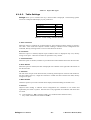
Join States
With the ‘join states’ option, adjacent equal condition states for each condition are displayed only
once (default). When unchecked, all states are repeated in every column.
Connect
Adjacent states leading to identical action configurations are then combined in one column and
separated by this word or symbol.
E.g. if the separator is OR, two adjacent states state 1 and state 2, leading to an identical
result, will be combined in the table into state 1 OR state 2.
2.4.3.
Table Net Settings
These settings allow you to modify the layout of the Project Net (showing the relations between
tables in a project).
2.5.
Advantages of Decision Table Automation
The construction of decision tables is a creative activity but it contains several routine operations
which are quite time-consuming and error-prone. The use of a decision table tool does not only
simplify the construction of the decision table, it also offers a number of extra advantages.
2.5.1.
The Theory behind Decision Table Construction
Before considering computer support, we will first treat the manual ways to construct decision
tables.
The choice of a suitable construction method will simplify the construction process and will
increase both its efficiency and effectiveness. Depending on the characteristics of the problem
domain, several methods can be distinguished. (VERHELST[80, chapter 2]):
1. the direct method : for well defined problems where specifications are relatively easy
to find (specifications that are readily available, e.g. a text., are no guarantee that
they are also easy to collect).
a) based on simple rules : can be applied in all cases, is recommended once
problems have a certain complexity.
b) based on combined rules : for small or simple problems.
2. the search method : for problems not too well defined where it is difficult to obtain
the specifications or where the specifications still have to be constructed.
These three methods follow comparable phases for analyzing the problem. The main difference
between these methods is the order in which these phases are dealt with and the way they are
worked out.
The following phases can be distinguished:
Prologa User's Manual
- 24 -
2. The Prologa System
1. Define the conditions, the condition states and the actions.
The following steps have to be undertaken:
1.1. Draw up the list of all condition statements and actions that are mentioned in the
specification.
1.2. Delete the restatements and the complements from this list.
1.3. Bring together the condition statements that are related to one condition subject
such that an exhaustive set of mutual disjoint states is obtained for that
condition.
1.4. Fill out the names of conditions and actions in the stub of the table. (Choose
any natural order for the actions and conditions, taking into account possible
order restrictions.)
2. Define the rules
During this phase, we describe the problem as a series of logical IF ... THEN ...
relations where the connection is made between a combination of condition states
and the actions that must be executed.
The following steps have to be dealt with:
2.1. Conceive the problem situation (without interpretation).
2.2. Determine the impossible condition combinations and the other relations
between the conditions (or actions).
2.3. Describe the problem using logical expressions.
3. Fill out the decision table.
A distinction can be made between filling out the action part and the condition part
of the table:
3.1. Fill out the condition entries of the table (the lower conditions will vary first).
3.2. Indicate all impossibilities.
Depending on the preferred option, the
impossibilities can be represented in the table in several ways.
3.3. Fill out the action entries (column by column or action by action).
4. Check for completeness, correctness and consistency
4.1. Examine the empty columns. These columns should to be examined one by one
to verify if it really was the intention to have no actions.
4.2. Examine the unreferenced actions (or conditions).
4.3. Examine the completeness of actions and columns. Some actions or groups of
actions should have at least one occurrence. This is usually the case if the
actions are the representation of an "extended-entry" action (exhaustivity
requirement).
4.4. Examine the table for contradictions. Some actions or action groups may
exclude each other and therefore cause contradictions if they occur in the same
column (exclusivity requirement).
4.5. Examine the table for correctness. Here we should not only check if the
different columns correspond with the described specifications, but also if this
specification corresponds with the desired reality.
Prologa User's Manual
- 25 -
2. The Prologa System
5. Simplify the decision table
5.1. Contraction of the table. Adjacent columns with the same action-configuration
are contracted into combined columns. An optimal condition order might be
computed to minimize the number of columns.
5.2. Decide upon a suitable layout. To achieve this, several actions can be combined
into extended entry actions, as long as this does not cause any contradictions.
6. (Transform the decision table)
6.1. Depending upon its purpose, the decision table might be converted into a
consultation system, a program with minimal execution time, etc.
2.5.2.
Why use a decision table tool?
The use of a computer does not only simplify the construction of the decision table, it also offers a
number of extra advantages.
We enumerate the advantages ordered by increasing involvement of computer use:
. The writing and drawing that has to be performed when constructing decision
tables, can be taken over completely by the computer.
. A number of routine jobs that induce many errors while filling out (or especially
when changing) the table, can be completed faster and more correct by the
computer, for instance: adding action entries, generating the condition combinations
(without any missing combinations).
. Some manipulations of the decision table which are difficult to perform manually,
such as the reordering of conditions and actions, can easily be performed now.
. Introducing a workbench in the design process provides interactive possibilities that
simplify the design process, such as automatic checking for consistency, correctness
and completeness or recommendations for a specific construction method.
. The system can be used for optimization purposes, such as optimal contraction,
layout, decomposition into subtables or conversion into efficient program code.
2.6.
Prologa and Validation of Knowledge
It is important that knowledge in decision situations is correct, consistent, complete and nonredundant. During and after the building process, the knowledge base must be verified and
validated, which proves to be one of the main problem areas in designing intelligent systems.
Knowledge validation occurs at several instances during the building process:
• A first validation takes place during the knowledge elicitation stage. When acquiring
knowledge, the knowledge engineer will look for incomplete specifications, ambiguities,
redundancies in order to direct and improve the elicitation process.
Prologa User's Manual
- 26 -
2. The Prologa System
•
In the knowledge modeling stage, the development interface of the system building tool
will (or should) verify the knowledge structuring effort (not only syntactical elements, but
also semantics). Very often, graphical representations of links between knowledge
elements are used in this stage.
•
When the application has been designed, the knowledge base has to be tested (using
prototyping facilities, debugging, test data management, reasoning trees, tracing and
logging).
•
The validation process resumes while maintaining the knowledge base.
In a vast majority of cases, the decision table technique is able to provide for extensive validation
and verification assistance(MERLEVEDE & VANTHIENEN [91]). It easily enables the designer
to check for contradictions, inconsistencies, incompleteness, redundancy, etc. in the problem
specification. Moreover, the knowledge acquisition process is well served through the overview
and communication abilities of well-structured decision tables.
Prologa easily solves (or avoids) these common validation problems in rule based systems, e.g.
redundant rules, conflicting rules, subsumed rules, unnecessary conditions, circular rules, missing
rules or combinations, unreferenced attribute values, illegal attribute values, dead end clauses.
2.6.1.
Consistency and Correctness of Knowledge
Dividing the knowledge over a large number of rules, designed independently, may lead to
problems of consistency (LOVELAND & VALTORTA1, BRAMER2), such as:
-
Conflict: rules with the same premises (or containing overlapping combinations), but leading
to contradictory conclusions.
In a decision table all columns are non-overlapping and each column refers to exactly one
configuration of conclusions, therefore conflict will not occur. During the building process,
Prologa allows the designer to override previous configurations or will indicate
contradictions in the table;
-
Cyclical rules: a set of rules where a conclusion occurs somewhere as one of the premises.
In a decision table context, conclusions occurring as premises lead to separate tables. The
forward character of the decision table structure, though less flexible in general, eliminates the
problem of cyclical references;
-
Invalid attribute values: a rule containing a nonexistent value of an attribute (e.g. because of
a typing error).
By defining the domain of conditions and performing type checking, invalid values are easily
detected;
-
Unreachable conditions: conditions which cannot be asked or concluded from other rules are
easily discovered in a set of decision tables.
1.
LOVELAND, D., VALTORTA, M. [83], Detecting Ambiguity : An Example in Knowledge Evaluation, Proc. Eighth
Intl Joint Conf. on Artificial Intelligence, Karlsruhe, Aug. 1983, Vol. 1, pp. 182-184.
2.
BRAMER, M. (Ed.), Research & Development in Expert Systems, Proc. Fourth Technical Conf. on Expert Systems,
Cambridge University Press, 1985, 228 pp., pp. 185-192.
Prologa User's Manual
- 27 -
2. The Prologa System
2.6.2.
Non-redundancy of Knowledge
Redundancy usually does not lead to errors during consultation of the system, but may harm
efficiency. The main problem with redundancy, however, is not inefficiency, but maintenance and
the risk of creating inconsistencies when changing the knowledge base. Moreover, the uncertainty
calculations might be affected by redundant knowledge. Some common forms of redundancy:
-
Subsumption: rules with the same conclusions but with one of them containing additional
premises (and therefore being less general).
Subsumption will not occur in the decision table, because columns do not overlap;
-
Redundant premises: (partly) complementary rules with equal conclusions, which can be
combined.
In a compressed decision table, two or more complementary rules with equal action
configurations are automatically combined, leading to irrelevant or partly irrelevant conditions.
The number of distinct columns is thereby minimized. Prologa will also indicate conditions
which are never referenced;
-
Redundant rules: rules with the same premises and (partly) equal conclusions.
Because in the decision table every possible case is included in only one column (exclusivity),
redundancies will not occur.
2.6.3.
Completeness of Knowledge
No current system is able to incorporate all possible knowledge, but within the specific problem
area, the following omissions often occur:
-
Missing knowledge: the absence of some essential elements from the problem situation.
Inconsistency e.g. might indicate missing premises;
-
Unused attribute values or combinations: when possible attribute values (or combinations)
never occur as premises, a number of rules is missing. Detecting the completeness of all
combinations of attribute values is not always simple.
The nature of the decision table easily allows to check for completeness: the number of simple
columns should equal the product of the number of states for every condition. This guaranty of
completeness of condition combinations is one of the main advantages of decision tables.
Prologa will automatically generate all combinations and indicate attribute combinations
where no conclusions are provided;
-
Unreachable conclusions: conclusions which are never deduced and cannot be asked.
The format of the decision table easily shows unreachable conclusions. Prologa will indicate
conclusions which are never referenced.
Detecting these shortcomings (either by the designer or automatically), without some form of
decision tables, is highly improbable, unless through excessive testing, which is already a problem
due to the current lack of automatic testing facilities.
Prologa User's Manual
- 28 -
2. The Prologa System
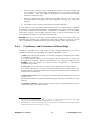
3. Prologa Step By
Step
Other chapters explain the theory behind Prologa, as well as the Prologa tool. The best way to
understand these chapters fully is by using the tool. This chapter describes four applications of
decision tables, each one is modeled using Prologa. The first two examples are completely
worked out and explain step by step how the problem can be solved. The third problem is
discussed from a theoretical point of view. The fourth problem if left as an exercise to the reader.
The solutions to the problems can be found on the distribution disk.
For the first two examples, the direct method for constructing a decision table will be used starting
from a text. We will guide you through a complete session, from knowledge acquisition to the
implementation of the resulting decision table(s). It is however not the purpose to explain all
Prologa screens again. We strongly recommend to make this exercise using the computer.
3.1.
Holidays, A simple one-table example
The first application is a simple knowledge based system that will be used by the Personnel
Department of a small company. We will assume that the resulting code has to be embedded in a
program.
The first step in the development process is knowledge acquisition. If information is available in
written form, this knowledge can easily be structured using the direct method for constructing
decision tables. This is often the case for existing regulations in a business environment.
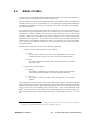
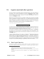
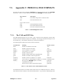
The text found in the rule book of the company is depicted in the following figure.
HOLIDAYS
The number of holidays depends on age and years of service.
Every employee receives at least 22 days.
Additional days are provided according to the following criteria:
Young employees (less than 18) receive 5 extra days.
If an employee has at least 25 years of service, 2 extra days are given. These 2 days
are also provided for employees of age 45 or more, irrespective of their years of
service.
Employees with at least 40 years of service and also employees of age 60 or more,
receive 3 extra days, on top of the additional days already given.
Figure 3-1. The regulations for holidays, as found in a rule book
Prologa User's Manual
- 29 -
3. Prologa Step By Step
The phases for analyzing the problem have been described elsewhere. We will go through these
phases step by step and build the decision table using Prologa.
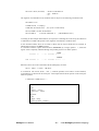
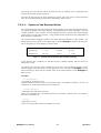
3.1.1.
Start new table
Start Prologa, and select New from the File menu. When saving, enter Holidays as table name.
Figure 3-2. Starting a new table
3.1.2.
Define the Conditions, Condition States and Actions
First we draw up the list of all condition statements and actions that are mentioned in the text. The
result can be seen in the following table.
Condition Statements
Age
Years of Service
Every Employee
Less than 18
>= 25 years of service
Age >= 45 years
irrespective of years of service
>= 40 years of service
Age >= 60 years
Action Statements
Number of Holidays
At least 22 days
Additional days
5 extra days
2 extra days
2 extra days
3 extra days on top
Table 3-1. Exhaustive List of Condition Statements and Actions in text
Now we delete the restatements and the complements of the list:
Prologa User's Manual
- 30 -
3. Prologa Step By Step
Condition Statements
Less than 18
>= 25 years of service
Age >= 45 years
>= 40 years of service
Age >= 60 years
Actions
Assign 22 days
5 extra days
2 extra days
3 extra days
Table 3-2. Reordered List of Condition Statements and Actions
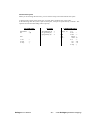
The list of condition statements has to be checked for completeness. Each condition should have
an exhaustive set of mutual disjoint states. This is done by putting the different states of a
condition on a scale, as can be seen in Figure 3-3.
Age
years < 18 | 18<= years < 45 | 45 <= years < 60 | years >= 60
Service
years < 25 | 25 <= years < 40 | years >= 40
Figure 3-3. Condition Scales for the Holiday Regulations
Based on these enumerations, we can now fill out the conditions, condition states and actions of
our decision table. This is done using the ‘+’ sign in the condition editor and action editor in
Prologa. Now the conditions can be entered together with their states. Enter the information
from Figure 3-3 into the Condition editor. Once this is done, also enter the actions from the
actions column. Your screen should then look similar to the screen depicted in Figure 3-4.
Figure 3-4. Prologa's Condition and Action Editor
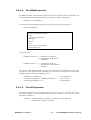
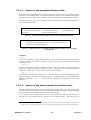
3.1.3.
Define the Decision Rules
Based on the text of the regulations and on the conditions, the condition states and the actions, we
can now proceed by filling out the rules in the Prologa Rule Editor. We simply read each line in
Prologa User's Manual
- 31 -
3. Prologa Step By Step
the regulations and translate it into a Prologa rule. These rules can be entered immediately into
the rule editor.
Every employee receives at least 22 days
Action 1 always has to be performed: there are no conditions. Just entering the action will do.
Type: 1
As you will see, Prologa will translate the entry into a more readable form. In this case this will
give the following result:
Result: 1 definitely if always
Figure 3-5. Entering a decision rule
Young employees (less than 18) receive 5 extra days
Action 2 (5 extra days) has to be performed if Age<18. This condition corresponds to state 1a.
Since we always enter the action first, the resulting rule is entered as follows:
Type: 2 if 1a
Result: 2 generally if 1a
For the two following rules we just give the result. The reasoning behind it is left as an exercise.
If an employee has at least 25 years of service, 2 extra days are given. These 2 days are also
provided for employees of age 45 or more, irrespective of their years of service.
Result: 3 generally if (2b or 2c) or (1c or 1d)
Employees with at least 40 years of service and also employees of age 60 or more, receive 3 extra
days, on top of the additional days already given.
Result: 4 generally if 2c or 1d
Notes
States of one condition can only be connected by OR. Therefore (2b or 2c) can be
abbreviated to 2bc.
The rules 3 and 4 can also be split up in several rules. There is no obligation at all to have
only one rule per action. For instance, we could replace the third rule by the following two
rules:
3 generally if (2b or 2c)
3 generally if (1c or 1d)
Prologa User's Manual
- 32 -
3. Prologa Step By Step
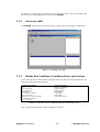
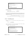
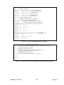
3.1.4.
The constructed Decision Table
While conditions, actions or rules are entered, the decision table view is always up to date. This is
performed automatically by Prologa. After entering the decision rules, the table looks as
depicted in Figure 3-6.
Figure 3-6. A first View of the Decision Table
3.1.5.
Verify Completeness and Consistency
Empty columns, unreferenced actions or unreferenced conditions do not occur in this example.
When, however, we take a good look at the preliminary decision table, we see that it should be
impossible for an employee younger than 18 years to have 25 or more years of service. Indeed,
this case was not excluded by the rules. Of course, we would probably prefer to discard this
impossible situation. This can be done by adding a new rule, stating that an employee younger
than 18 definitely cannot be more than 25 or more than 40 years in service. Since children are not
allowed to work, we can also add a rule that employees younger than 45 can not have 40 years of
service in the company.
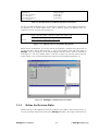
Result:
impossible definitely if 1a and (2b or 2c)
impossible definitely if 1b and 2c
Note
We strongly recommend the use of impossibilities.
In fact, one should look for semantic impossibilities before entering the rules. Deletion of
impossible situations will ease the verification process.
By definition, semantic impossibilities should be used in combination with "definitely if". If
"generally if" would be used, other rules could overrule this impossibility.
Prologa User's Manual
- 33 -
3. Prologa Step By Step
Figure 3-7. The final Decision Table
3.1.6.
Validate Correctness
This last check is a double one. First we verify if the different columns of the decision table
correspond with the described specifications. For this example this is the case. If this is not the
case, it means that the interpretation of the text is wrong, or in other words one of the rules does
not correspond to the text.
Second, one has to check if the decision table corresponds to the desired reality. For instance, it
could be possible that management would prefer to give an extra day after 10 years in service,
even if this is not mentioned in the text. This is exactly what has to be checked: (1) does the text
fully represent the current situation?, and (2) does it represent the desired situation?
3.1.7.
Simplify the Decision Table
Once a complete validation of the decision table is finished, the table should be reduced to its
minimal format. We strongly recommend the use of the expanded table for knowledge
verification! This form gives a better overview, especially to compare the decision table with the
desired reality. To view the expanded table, press the “expand” button in the table menu.
3.1.7.1.
Contraction of the decision table
As mentioned above, this is done automatically in Prologa when the table option “Start
Contracted” is checked (default).
3.1.7.2.
Decide upon the suitable layout
The order of the conditions might influence the number of columns in the contracted table. The
optimal order can be obtained using Prologa. Select the Optimize Table button from the table
menu. For this example, the original condition order is already the optimal one.
Prologa User's Manual
- 34 -
3. Prologa Step By Step
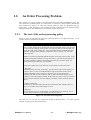
3.2.
An Order Processing Problem
This example is a typical example of the application of decision tables (VERHELST [80]). We
have chosen this problem because it is well suited to construct a system of tables, and because
some 'mistakes' are built in. It shows why decision tables are better for regulations than e.g.
written texts. In this example we start from the text used to take decisions for order processing.
During the decision table validation several 'mistakes' will be discovered.
3.2.1.
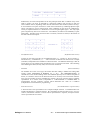
The text of the order processing policy
Figure 3-8 gives the complete text of the order processing policy as it is applied currently. As we
will see, this text contains some 'mistakes'.
Order Processing
First we check whether the credit limit has not been exceeded. If this is not the case,
the stock will be checked. If the product is in stock, the order will be executed, else
we put the order on the waiting list. If the credit limit has been exceeded, the same
measures will apply if the customer is important. If this is not the case, the order
will be rejected
Whether a customer is important depends primarily on the age of the account. If the
customer did register less than a year ago, the turnover over the last 6 months has to
be at least $10,000 to qualify as an important customer. For all other clients, the
critical turnover point has been set to $5,000$.
Three critical points have to be taken into account while executing the order :
1. Discount
The discount rates are 10%, 5% and 2% : 10% for clients with an order quantity of
at least 15 pieces or who are situated within a range of less than 50 miles of the
company and order at least 10 pieces; a discount of 5% is allowed to those
customers that order at least 10, but less than 15 pieces and whose distance to the
company is more than 50 miles; finally, the discount rate comes to 2% for customers
that live at least 100 miles from the company, and order at least 10 but less than 15
pieces.
2. Means of Transport
We deliver by rail if the order comes from a customer that has ordered at least 15
pieces. In all other cases, road transport is used.
3. Bill Type
The normal bill type is A. Exceptionally, a type B bill has to be made up. This is
the case when a customer's order quantity is at least 15 pieces.
Figure 3-8. The Order Processing Policy
With this text, we can start the construction method of decision tables. As in the previous
example, all steps will be discussed in detail.
Prologa User's Manual
- 35 -
3. Prologa Step By Step
3.2.2.
Defining subproblems
After careful reading of the text, one can see that it is quite difficult to represent the problem by
one table. Indeed, already in the first paragraph enough indications show that some subtables have
to be used. First, there is the decision whether a customer is important or not. This decision is
discussed in the second paragraph. We prefer to put this decision in a condition subtable. Second,
the action 'execute order' is worked out in the third part of the text. We prefer to see this action as
an action subtable.
From these considerations we deduce the following intuitive rule : When a problem can be split up
in clearly defined subproblems, the decision table should have subtables.
Since the order processing policy is now split out over three tables, we have a table structure. For
real problems, we will often have even more tables.
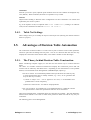
The particular table structure, which will be reached at the end of this example, is shown in Figure
3-9.
Figure 3-9. The table structure for the ORDERS problem
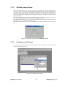
3.2.3.
Starting a new Project
In order to input the first table, we start a new project (‘Orders’) and choose a name for the first
table, as indicated in Figure 3-10.
Figure 3-10. Starting a new project
Prologa User's Manual
- 36 -
3. Prologa Step By Step
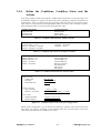
3.2.4.
Define the Conditions, Condition States and the
Actions
Since the procedure for deriving conditions, condition states and actions is exactly the same as for
the Holidays example, we only give the final results (after regrouping, restatement and deletion of
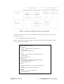
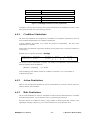
complements). Table 3-3 represents the first paragraph, which will result in the ‘Decide on Order’
table, Table 3-4 represents the second paragraph, which will result in the ‘Evaluate Customer’
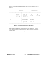
table and finally Table 3-5 will result in the ‘Execute Order’ table.
Condition Statements
Credit Limit OK
Customer Good
Stock Sufficient
Action Statements
Execute Order
Refuse Order
Put On Waiting List
Table 3-3. Conditions and actions for ‘Decide on Order’
Condition Statements
Age of Account < 1 year
Turnover / 6 months >= $10,000
Turnover / 6 months >= $5,000
Action Statements
Customer := Not Good
Customer := Good
Table 3-4. Conditions and actions for ‘Evaluate Customer’
Condition Statements
Quantity ordered >= 15
Quantity ordered >= 10
Distance < 50 miles
Distance < 100 miles
Action Statements
Discount Rate 10%
Discount Rate 5%
Discount Rate 2%
Railway Transport
Road Transport
Bill Type A
Bill Type B
Table 3-5. Conditions and actions for ‘Execute Order’
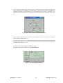
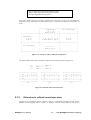
Decide on Order
Credit Limit
Customer
Stock Sufficient
OK | Not OK
Good | Not Good
Yes | No
Evaluate Customer
Age of Account
Turnover / 6 months
< 1 year | >= 1 year
< 5,000 | 5,000 - < 10,000 | >= 10,000
Execute Order
Quantity Ordered
Distance (Miles)
< 10 | 10 - < 15 | >= 15
< 50 | 50 - < 100 | >= 100
Figure 3-11. Condition Scales for the order processing problem
Based on these enumerations, we can fill out the conditions, condition states and actions for the
three tables. By entering ‘^Customer’ as the condition name, and ‘^Execute Order’ as the action
name in the main table, the two subtables are created.
Prologa User's Manual
- 37 -
3. Prologa Step By Step
3.2.5.
Define the Rules
Based on the text of the policy we now define the rules for the three decision tables. Rules are
entered in the Prologa Rule Editor.
3.2.5.1.
The rules for ‘Decide on Order’
The first paragraph of the text already shows that this problem is formulated in a more complex
way than the Holidays example we treated in the first part of this chapter. Here we really have to
read the text carefully line by line to understand what is really meant.
First we check whether the credit limit has not been exceeded. If this is not the case, the stock will
be checked. If the product is in stock, the order will be executed, else we put the order on the
waiting list.
If the credit limit has been exceeded, the same measures will apply if the customer is important. If
this is not the case, the order will be rejected
It is not possible to translate each line of this regulation in one decision rule, as we did in the
Holidays example. This approach can only be followed if the lines or sentences are really
independent of each other. Therefore we turn to the actions. For each action a separate rule is
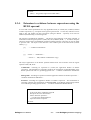
deduced from the text :
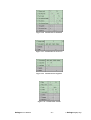
Execute Order if (Credit Limit OK or (Credit Limit not OK and Customer Good))
and Stock Sufficient
1 generally if only 1a or (1b and 2a) and 3a
Refuse Order if Credit Limit not OK and Customer not Good
2 generally if only 1b and 2b
Put On Waiting List if (Credit Limit OK or (Credit Limit not OK and Customer Good))
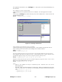
and Stock not Sufficient
3 generally if only 1a or (1b and 2a) and 3b
Figure 3-12. The table ‘Decide on Order’
Note: The 'if only' (= if and only if) operator indicates that the specific action is only applicable in
the cases mentioned. In all other cases the action will not be executed. Therefore a '-' symbol is
introduced in the decision table for all other columns of the action row.
Prologa User's Manual
- 38 -
3. Prologa Step By Step
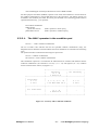
3.2.5.2.
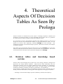
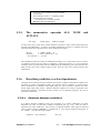
The rules for ‘Evaluate Customer’
If the customer did register less than a year ago, the turnover over the last 6 months has to be at
least $10,000 to qualify as an important customer. For all other clients, the critical turnover point
has been set to $5,000$.
Only 2 generally if 1a and 2c or 1b and 2bc
(1)
In all other cases, the customer is not good.
Only 1 generally if not rule 1
(2)
This second rule illustrates the power of Prologa's decision rule syntax. One can refer to another
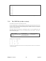
rule for the conditions of a new rule. Here we negate the conditions of rule 1.
Note: It is possible to write something like NOT (Rule 1 OR Rule 2 OR Rule 3).
However, this might lead to a combinatorial explosion. We recommend the use of the Rulestatement for the negation of one earlier rule only.
Figure 3-13. The table ‘Evaluate Customer’
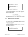
3.2.5.3.
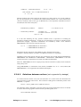
The rules for ‘Execute Order’
1. Discount
The first of the three paragraphs deals with the discount that will be given. This paragraph can be
cut into 3 parts, one for each reduction rate:
10% for clients with an order quantity of at least 15 pieces or who are situated within a range of
less than 50 miles of the company and order at least 10 pieces;
1 generally if only 1c or 1bc and 2a
(1)
a discount of 5% is allowed to those customers that order at least 10, but less than 15 pieces and
whose distance to the company is more than 50 miles;
2 generally if only 1b and 2bc
(2)
finally, the discount rate comes to 2% for customers that live at least 100 miles from the company,
and order at least 10 but less than 15 pieces.
3 generally if only 2c and 1b
Prologa User's Manual
(3)
- 39 -
3. Prologa Step By Step
We suppose that all other situations lead to a discount of 0%. Although this action was not
specifically mentioned in the text, we already add it, as it will come up as a result of the
verification process later.
We consider Means of Transport and Bill Type together:
2. Means of Transport
We deliver by rail if the order comes from a customer that has ordered at least 15 pieces. In all
other cases, road transport is used.
3. Bill Type
The normal bill type is A. Exceptionally, a type B bill has to be made up. This is the case when a
customer's order quantity is at least 15 pieces.
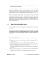
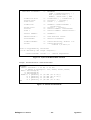
These 2 paragraphs result in the following rules:
5 and 8 generally if only 1c
6 and 7 generally if not rule 4
(4)
(5)
Figure 3-14. The preliminary table ‘Execute Order’
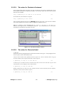
3.2.6.
Fill out the Decision Tables
As already explained, this step is performed automatically by Prologa. If the table contraction
option is checked, the tables will look as shown above.
Prologa User's Manual
- 40 -
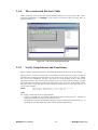
3. Prologa Step By Step
3.2.7.
Check
for
Consistency
Completeness,
Correctness
and
For the ‘Decide on Order’ and for the ‘Evaluate Customer’ decision tables there are no real
verification problems. We leave these two tables as an exercise and turn immediately to the third
table ‘Execute Order’.
3.2.7.1.
Examine the empty columns
No empty columns are present in the decision table.
3.2.7.2.
Examine the unreferenced actions and conditions
When we look at the ‘Execute Order’ table with the current set of rules, we can see that action 4
(‘No discount’) is still unreferenced. This is normal because we did not define a rule for this
action.
3.2.7.3.
Examine the completeness of actions and columns
Column 1 of the table does not contain a discount value. Probably we want action 4 (‘No
discount) for this column. However, this is not mentioned in the text and therefore was not
included in the rules.
3.2.7.4.
Examine the table for contradictions
There is a contradiction in column 4. When the quantity is between 10 and 15 pieces and the
distance is more than 100 miles, the customer would get 2 discounts (5% and 2%). Since we
presume that the discount rates exclude each other, this has to be wrong. At least one of the
decision rules leading to this conclusion will have to be changed.
3.2.7.5.
Examine the table for correctness
The decision table fully represents the text of the order processing policy. However, this policy
contains contradictions and is not really complete. Using the text can result in different reductions
depending on how it is read. The company has to adapt its policy to make it consistent.
We can assume that the following text was really meant:
The discount rates are 10%, 5%, 2% and 0% :
- 10% for clients with an order quantity of at least 15 pieces or who are situated within a range
of less than 50 miles of the company and order at least 10 pieces;
- a discount of 5% is allowed to those customers that order at least 10, but less than 15 pieces
and whose distance to the company is more than 50 miles but less than 100 miles;
- the discount rate comes to 2% for customers that live at least 100 miles from the company, and
order at least 10 but less than 15 pieces.
- If none of the previous cases can be applied, no discount (discount rate = 0%) has to be
given.
This text is corresponds to the ‘Orders’ decision table project as it can be found on the distribution
disk.
Prologa User's Manual
- 41 -
3. Prologa Step By Step
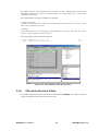
Figure 3-15. The final tables for the order processing example
3.2.8.
Simplify the decision tables
As described earlier, two simplifications can be made:
- contracting the table with the same condition order (was done automatically by Prologa);
- applying optimal contraction, looking for the condition order that results in the smallest table.
No improvements to be made in this example.
Prologa User's Manual
- 42 -
3. Prologa Step By Step
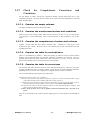
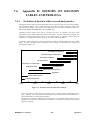
3.3.
Different ways to solve a classification
Problem
An example is given of a small deterministic expert system for animal classification. The purpose
of this system is to determine the (sub)category and, possibly, the name of a specific animal, from
a number of observed attributes. This example illustrates how the decision table approach not only
preserves the advantages of rule based systems (through the formulation of decision rules), but
also offers (i) a better overview, (ii) ease of checking for completeness and consistency, and (iii) a
more efficient execution.
This example has not been worked out completely, as was the case for the two previous exercises.
However, since the solution is illustrated quite well, it shouldn't be a problem to try it out yourself.
The problem described, of course, does not claim completeness. It is meant to illustrate the
influence on the classification, of a limited number of similar attributes (the importance of the
distinction between necessary and/or sufficient conditions), e.g. :
- necessary, but not sufficient : every bird lays eggs, but not every animal which lays eggs is a
bird;
- not necessary, but sufficient : every animal giving birth to living creatures is a mammal, but
there are other mammals;
-
not necessary, not sufficient : not every bird can fly and not every animal which flies is a bird.
An overview of all the rules used in this classification problem (from PARK1), is supplied in
Figure 3-16. The same problem is described in BORLAND2, as the rule base of a (Turbo) Prolog
program (See Figure 3-17).
1.
See pp. 56-58 in: PARK, J. [83], MVP-FORTH Expert System Toolkit, Knowledge-Based Inference Program,
Mountain View Press, Mountain View (Cal.), 1983.
2.
BORLAND INTERNATIONAL INC. [86], Turbo Prolog Owner's Handbook, Scotts Valley, California, 1986, 221 pp.
Prologa User's Manual
- 43 -
3. Prologa Step By Step
[1] IF
AND
NOT animal is a bird
animal has hair
THEN animal is a mammal
[10] IF
AND
AND
AND
animal
animal
animal
animal
is a mammal
is a carnivore
has tawny color
has bl. stripes
THEN animal is a tiger
[2] IF
AND
NOT animal is a bird
animal gives milk
THEN animal is a mammal
[3] IF
[11] IF
AND
AND
AND
animal
animal
animal
animal
is an ungulate
has a long neck
has long legs
has dark spots
animal has feathers
THEN animal is a giraffe
THEN animal is a bird
[4] IF
AND
animal flies
animal lays eggs
[12] IF
AND
animal is an ungulate
animal has bl. stripes
THEN animal is a zebra
THEN animal is a bird
[5] IF
AND
NOT animal is an ungulate
animal eats meat
THEN animal is a carnivore
[13] IF
AND
AND
AND
AND
animal is a bird
NOT animal flies
NOT animal swims
animal has a long neck
animal is black/white
THEN animal is an ostrich
[6] IF
AND
AND
AND
NOT animal
animal has
animal has
animal has
is an ungulate
pointed teeth
claws
forward eyes
THEN animal is a carnivore
[14] IF
AND
AND
AND
animal is a bird
NOT animal flies
animal swims
animal is black/white
THEN animal is a penguin
[7] IF
AND
animal is a mammal
animal has hooves
THEN animal is an ungulate
[8] IF
AND
animal is a mammal
animal chews cud
[15] IF
AND
AND
animal is a bird
animal flies
animal flies well
THEN animal is an albatross
THEN animal is an ungulate
AND animal has even toes
[9] IF
AND
AND
AND
animal
animal
animal
animal
is a mammal
is a carnivore
has tawny color
has dark spots
THEN animal is a cheetah
Figure 3-16. Rules for the animal classification problem
Prologa User's Manual
- 44 -
3. Prologa Step By Step
clauses
animal_is(cheetah) if
it_is(mammal) and
it_is(carnivore) and
positive(has,tawny_color) and
positive(has,black_spots).
animal_is(tiger) if
it_is(mammal) and
it_is(carnivore) and
positive(has,tawny_color) and
positive(has,black_stripes).
animal_is(giraffe) if
it_is(ungulate) and
positive(has,long_neck) and
positive(has,long_legs) and
positive(has,dark_spots).
animal_is(zebra) if
it_is(ungulate) and
positive(has,black_stripes).
animal_is(ostrich) if
it_is(bird) and
negative(does,fly) and
positive(has,long_neck) and
positive(has,long_legs) and
positive(has,black_and_white_color).
animal_is(penguin) if
it_is(bird) and
negative(does,fly) and
positive(does,swim) and
positive(has,black_and_white_color).
animal_is(albatross) if
it_is(bird) and
positive(does,fly_well).
it_is(mammal) if
positive(has,hair).
it_is(mammal) if
positive(does,give_milk).
it_is(bird) if
positive(has,feathers).
it_is(bird) if
positive(does,fly) and
positive(does,lay_eggs).
it_is(carnivore) if
positive(does,eat_meat).
it_is(carnivore) if
positive(has,pointed_teeth) and
positive(has,claws) and
positive(has,forward_eyes).
it_is(ungulate) if
it_is(mammal) and
positive(has,hooves).
it_is(ungulate) if
it_is(mammal) and
positive(does,chew_cud).
Figure 3-17. Prolog clauses for the classification of animals
Prologa User's Manual
- 45 -
3. Prologa Step By Step
If this problem is translated into decision tables, it is obvious that some conditions also appear as
actions elsewhere, thereby leading to a table hierarchy. The tree structure of the classification is
reflected in the table structure (Figure 3-18), with different levels of tables, according to the
subdivision in main categories (e.g. mammals, birds), subcategories (e.g. ungulates, carnivores),
etc.
Figure 3-18. Table structure of animal classification
As the problem description was not meant to be complete, some holes will remain in the final
decision tables (indicated with "...").
The main table (Figure 3-19), subdividing animals into birds and mammals (and calling the
respective tables with the "^" symbol), refers to the first four rules, which can be combined into
the following two decision rules :
[1] ^Bird IF Has feathers OR (Flies AND Lays eggs)
[2] ^Mammal IF (Has hair OR Gives milk) MINUS RULE 1
Figure 3-19. Classification of animals
Prologa User's Manual
- 46 -
3. Prologa Step By Step
Figure 3-20. Classification of mammals
Figure 3-21. Classification of carnivores
Figure 3-22. Classification of ungulates
Figure 3-23. Classification of birds
Prologa User's Manual
- 47 -
3. Prologa Step By Step
A complete overview of all decision rules for these classification tables, is presented in Figure
3-24.
Classification of animals
[1] ^Bird
[2] ^Mammal
IF Has feathers OR (Flies AND Lays eggs)
IF (Has hair OR Gives milk) MINUS RULE 1
Mammal
[1] ^Ungulate
[2] Has even toes
[3] ^Carnivore
IF Chews cud OR Has hooves
IF Chews cud
IF (Eats meat OR (Has pointed teeth AND
Claws AND Forward eyes)) MINUS RULE 1
Carnivore
[1] Cheetah
[2] Tiger
IF Tawny color AND Dark spots
IF Tawny color AND Black stripes
Ungulate
[1] Giraffe
[2] Zebra
IF Dark spots AND Long neck AND Long legs
IF Black stripes
Bird
[1] Impossible
[2] Ostrich
[3] Penguin
[4] Albatross
IF NOT Flies AND Flies well
IF NOT Flies AND Black & white AND NOT Swims
AND Long neck
IF NOT Flies AND Black & white AND Swims
IF Flies AND Flies well
Figure 3-24. Decision rules for the classification of animals
Prologa User's Manual
- 48 -
3. Prologa Step By Step
3.4.
First Aid to victims of poison
This example is left as an exercise to the reader. The following figure describes the problem for
which a decision table has to be built (VERHELST [80]).
First Aid to victims of poison
1. In any case, first try to dilute the poison by administering large quantities of
liquid (water, milk, ...). Then make sure the patient vomits. Repeat this dilute/vomit
procedure until all poison is removed from the stomach of the patient.
2. The preceding general guideline must not be applied if the poison was a strong
acid, strychnine or a petroleum product, nor when the patient lost consciousness.
3. If the poison was a strong acid, the poison has to be diluted with a small quantity
of water and then neutralized as fast as possible. Then protect the stomach by
administering normal kitchen oil. Make sure the patient does not vomit.
4. If the poison was strychnine, the procedure described under 1) should only be
applied if the poison was taken only a few minutes ago. Otherwise, do not disturb
the patient.
5. If the poison was a petroleum product, or if the patient lost consciousness, the
vomiting procedure should definitely not be applied. Keep the patient warm and do
not administer a liquid.
6. Independent of all previous points, try to find medical assistance as fast as
possible.
Figure 3-25. First Aid to victims of poison
Try to apply the decision table construction method. On the Prologa distribution disk you can
find a solution.
Prologa User's Manual
- 49 -
3. Prologa Step By Step
4. Theoretical
Aspects Of Decision
Tables As Seen By
Prologa
Decision situations are characterized by three aspects : knowledge acquisition, validation (and
maintenance), and decision making. In current knowledge based systems, little or no guarantees
are usually present to support validation, change and complexity control.
In a vast majority of cases, the knowledge acquisition and validation processes are well served
through the overview and communication abilities of well-structured decision tables. For this
purpose, the decision table engineering workbench Prologa has been developed. This
workbench incorporates rule based knowledge acquisition, table based verification, and adequate
consultation interfaces.
This chapter gives a background on decision tables as they are used in Prologa. First, the basics
needed to understand the advanced features of decision tables will be mentioned. The second
section deals with the description of the specification language used in Prologa.
4.1.
Decision tables
systems
and
knowledge
based
Decision tables and knowledge based systems show some striking similarities, although both
approaches put strongly different emphases. While decision tables traditionally stress the
representation facilities (with the resulting additional checking capabilities for completeness,
consistency and correctness), knowledge based systems are mainly dealing with knowledge
formulation (modularity, flexibility) and inference (performance, user friendliness).
In this manual it is argued that by using rule based design of decision tables, combined with a user
friendly consultation mechanism, the strong points of both approaches can largely be combined :
-
advantages of rule based knowledge acquisition (modularity, flexibility and simplicity);
Prologa User's Manual
- 50 - 4. Theoretical Aspects of Decision Tables
-
easy checking for completeness, consistency and correctness by designing decision tables;
high performance of the search process;
user friendly question driven interface.
As a lot of knowledge based systems which are being built nowadays use the rule based paradigm
to develop systems which are essentially deterministic decision trees, it seems that mainly two
aspects of current commercial expert system shells are used : a question driven user interface, and
second, a rule based knowledge acquisition, representation and inference scheme. Other facilities
(uncertainty, complex inference strategies, explanation facilities, heuristics, inductive learning) are
often not considered. This raises the question whether deterministic decision trees are expert
systems (HAYWARD1, VALIENTE2) or need expert system shells (see also LEITH3).
Irrespective of the answer to these questions, it seems useful to consider other alternatives to
obtain
both
desired
aspects
(the
user
interface
and
the
rule
based
design/representation/specification scheme) for handling deterministic decision situations. The
use of decision tables (using a decision table engineering workbench) is a promising alternative, as
it easily enables the designer to check for contradictions, inconsistencies, incompleteness,
redundancy, etc. in the rule base (VANTHIENEN [86], MAES & VAN DIJK4), which is one of the
major problems in building and maintaining expert systems (see e.g. LOVELAND & VALTORTA,
SUWA, SCOTT & SHORTLIFFE)5.
4.2.
Rule based decision tables
Even if at first sight decision tables in their current form look almost the same as years ago, their
use has changed a lot (see e.g. VERHELST [80], CODASYL [82], REILLY, SALAH & YANG6,
VANTHIENEN7).
A decision table is a tabular representation of a procedural decision situation, where the state
of a number of conditions determines the execution of a set of actions. Not just any
representation, however, but one in which all distinct situations are shown as columns in a
table, such that every possible case is included in one and only one column (completeness and
exclusivity).
An example of a decision table is presented in Figure 4-1.
1.
HAYWARD, S. [85], Is a Decision Tree an Expert System, in : BRAMER, M. (Ed.), Research & Development in
Expert Systems, Proc. Fourth Technical Conf. on Expert Systems, Cambridge University Press, 1985, 228 pp., pp. 185192.
2.
VALIENTE, G. [91], Are Complete K-Trees Something More Than Decision Trees, Sigart Bulletin, Vol. 2, No. 2,
ACM Press, April 1991, p. 6.
3.
LEITH, P. [90], Formalism in AI and Computer Science, Ellis Horwood Limited, Chichester, 1990, 225 pp.
4.
MAES, R., VAN DIJK, J. [88], On the Role of Ambiguity and Incompleteness in the Design of Decision Tables and
Rule Base Systems, ISRA Report 88/01, Universiteit van Amsterdam, 1988, 21 pp.
LOVELAND, D., VALTORTA, M. [83], Detecting Ambiguity : An Example in Knowledge Evaluation, Proc. Eighth
Intl Joint Conf. on Artificial Intelligence, Karlsruhe, Aug. 1983, Vol. 1, pp. 182-184.
5.
SUWA, M., SCOTT, A., SHORTLIFFE, E. [84], Completeness and Consistency in a Rule-Based System, in :
BUCHANAN B., SHORTLIFFE E., Rule Based Expert Systems, Addison Wesley Publishing Co., Reading (Mass.),
1984, pp. 159-170.
6.
REILLY, K., SALAH, A., YANG, C. [87], A Logic Programming Perspective on Decision Table Theory and Practice,
Data & Knowledge Engineering, 87(2), pp. 191-212.
7.
VANTHIENEN, J. [88], Een moderne kijk op beslissingstabellen, Informatie, December 1988, pp. 912-937.
Prologa User's Manual
- 51 - 4. Theoretical Aspects of Decision Tables
Figure 4-1. Example of a Decision Table
The tabular representation of the decision situation is characterized by the separation between
conditions and actions, on one hand, and between subjects and conditional expressions, on the
other. Every table column (decision column) indicates which actions should (or should not) be
executed for a specific combination of condition states. The condition oriented approach of the
decision table makes it very useful to display procedural knowledge, with such advantages as :
overview, readability, easy checking for consistency and completeness. Most of the common
validation problems in rule based systems (see e.g. NGUYEN et al.8, AYEL9, LIU & DILLON10) can
easily be solved using decision tables, e.g. redundant rules, conflicting rules, subsumed rules,
unnecessary conditions, circular rules, missing rules or combinations, unreferenced attribute
values, illegal attribute values, dead end clauses.
4.3.
The notation scheme of the decision table
The decision table is represented as a table which is split in two by a double line, both horizontally
and vertically, resulting in four quadrants. The horizontal line divides the table in a condition part
(above) and an action part (below). The vertical line divides subjects and entries in the stub (left)
and the entry part (right) respectively. As you can see in Figure 4-2, the resulting quadrants are :
condition stub, action stub, condition entries and action entries.
8.
NGUYEN, T., PERKINS, W., LAFFEY, T., PECORA, D. [87], Knowledge Base Verification, AI Magazine, 8(2),
1987, pp. 69-75.
9.
AYEL, M. [88], A Conceptual Model for Consistency of Knowledge Bases, in : O'SHEA, T & SGUREV, V. (Ed.),
Artificial Intelligence III : Methodology, Systems, Applications, North-Holland, 1988, pp. 75-82.
10. LIU, N., DILLON, T. [88], Detecting of Consistency and Completeness in Expert Systems using Numerical Petri Nets,
in : GERO, J. & STANTON, R. (Ed.), Artificial Intelligence Developments and Applications, North-Holland, 1988, pp.
119-134.1
Prologa User's Manual
- 52 - 4. Theoretical Aspects of Decision Tables
+----------------------------------------------------+
¦
¦
¦
¦
¦
¦
¦
Condition Stub
¦
Condition Entries
¦
¦
¦
¦
¦
¦
¦
¦---------------------+------------------------------¦
¦
¦
¦
¦
¦
¦
¦
Action Stub
¦
Action Entries
¦
¦
¦
¦
¦
¦
¦
+----------------------------------------------------+
Figure 4-2. Quadrants of a Decision Table
This strict separation between conditions and actions is not always as simple as it looks :
·
Some actions (initializations, bound actions) have to be executed before testing certain
conditions. This problem can often be solved by using initializations (possibly condition
subtables), but this results in a quite complex notation. If the problem cannot be solved this
way, the table will have to be split in subtables;
·
Some actions can already be executed after testing one or more conditions. This "rising" of
actions (called hoisting) has the advantage that the relation with the conditions involved is
illustrated more clearly. However, in general this mixing of conditions and actions will result
in complex tables, thus loosing the overview. After all, since putting the action earlier is not
strictly required because there are no order restrictions, this is already an attempt to optimize
the table.
The entries part consists of columns (with condition states and action values) separated by a
vertical line from the first different condition state. A column then contains a state for each
condition or a contraction of states which yields the same result (with eventually "irrelevant" ("-")
if this is the case for all states), followed by the resulting value for each action.
The order of the columns shows that only single hit tables are taken into account, in other words,
each situation is present in only one column and, consequently, the columns will not interfere with
each other. This excludes the use of the so called multiple hit tables, where a particular situation
can be present in several (partially overlapping) columns, such that the order of the columns is
determining their application area, which strongly reduces the overview and the validation
possibilities.
If each column only contains simple states (no contractions or irrelevant conditions), the table is
called an expanded decision table (canonical form), in the other case the table is called a
contracted decision table (consolidated form). The transition from one form to the other is defined
as expansion (rule expansion) and contraction (consolidation) respectively.
The condition names or action names in the stub can refer to other tables (subtables). The
replacement of these references by the tables themselves, the junction of tables, is called (table)
expansion. The reverse process, the division into subtables, is defined as factoring.
Some combinations of conditions may be impossible, in other words, they cannot occur. Such
combinations may be deleted from the table (see further). Keep in mind that only real
impossibilities are to be deleted, combinations that should not occur must stay in the table, since at
one moment or another this might be the case (according to Murphy's Law).
Prologa User's Manual
- 53 - 4. Theoretical Aspects of Decision Tables
4.4.
Kinds of tables
In practice one has to distinguish between different kinds of tables, with the decision grid chart at
one end of the spectrum and the decision table at the other end.
The most important criterion when distinguishing tables, is the question whether all columns are
mutually exclusive (single hit versus multiple hit). In a single hit table each possible combination
of condition can be found in exactly one (one and only one) column. This makes an unambiguous
use of the table possible.
If the columns are not exclusive, the first hit rule will often be used. This rule states that the first
hit (from left to right) will determine which set of actions has to be executed, thus preventing
contradictions. Another possibility is that all hits are used to determine the set of actions to be
executed. In this case, each hit from left to right can add actions (not mentioned by previous
columns) or delete actions (contradiction with previous columns) to the set. This is the procedure
applied for decision grid charts. In both cases (first hit versus all hits) the same combination of
conditions can occur in different columns of the table. As a result the overview over the columns
is lost, and with it, the simplicity of inspection. For these reasons we do not consider these tables
to be decision tables.
Based on these considerations, we propose the following subdivision:
1. multiple hit tables (tables with non-exclusive columns)
a) all hits
the rule table or decision grid chart (table representation of the (action
oriented) rule base) that serves as a basis to construct the decision table;
b) first hit
the "classic" multiple hit decision table as end product, has to be evaluated
from left to right;
2. single hit tables (decision tables)
a) expanded
the condition oriented table representation of all single decision columns,
used to check whether the table is correct and completely filled out;
b) contracted
the compact, condition oriented, table representation of all decision
columns.
This grouping does not imply that one form is always better than the others. It has been mentioned
that the decision grid chart (rule base) primarily has a specification function, and that the expanded
table has a verification function. When constructing decision tables we will use both forms in this
order, as steps in the process leading to the contracted table. In this context MAES & VAN
DIJK11 discuss the lifecycle of the decision table, distinguishing between 'construction time', 'test
time' and 'interpretation time' decision tables (respectively corresponding to the types 1a), 2a) and
2b)).
11. MAES, R., VAN DIJK, J. [88], On the Role of Ambiguity and Incompleteness in the Design of Decision Tables and
Rule Base Systems, ISRA Report 88/01, Universiteit van Amsterdam, 1988, 21 pp.
Prologa User's Manual
- 54 - 4. Theoretical Aspects of Decision Tables
4.5.
Detailed discussion of form, contents and
pragmatics of the decision table
Over the years the decision table has been subject to several adaptations and extensions. These
changes dealt with both contents and cosmetics. The numerous extra features cause a loss of
simplicity and uniformity. The effect is that the power and the applicability of the technique are
rather reduced, instead of enlarged. Therefore it is recommended to respect a number of
simplifications and standards. The following paragraphs impose a number of constraints to the use
of the decision table technique. The constraints deal with the form as well as with the contents of
the tables which are used (see also VERHELST [80], CODASYL [82]). These restrictions mainly
emanate from the need to use the decision table as a well structured tool for the application area :
·
Exclusivity and completeness of the columns
(Single hit tables)
The decision table, defined as a mapping of the Cartesian product of the condition states to the
Cartesian product of the action values by which every condition combination is mapped onto
one and only one action configuration, has to meet the demand of completeness and exclusivity
with respect to. the columns. Therefore, each combination of conditions has to be included in
one and only one column of the decision table. If this is not the case, the validation and the
adaptation of the table will be next to impossible. This excludes the use of the multiple hit
tables (with partially overlapping columns), where the following ambiguities and
incompletenesses are possible (which often results in the agreement that the columns should be
evaluated from left to right) :
+-----------------------+
¦ Condition ¦ Y ¦ N ¦ - ¦
+-----------------------+
·
Multi-valued states
+-------------------------+
¦ Condition x ¦ Y ¦ - ¦ Y ¦
+-------------+---+---+---¦
¦ Condition y ¦ Y ¦ N ¦ N ¦
+-------------+---+---+---¦
¦ Condition z ¦ - ¦ N ¦ Y ¦
+-------------------------+
(Extended entry conditions)
The distinction between tables with limited, mixed or extended entries (limited, mixed- or
extended-entry tables) is outdated. The condition part consists essentially of a number of
conditions with a number of values ("states") for these conditions. Whether a condition
happens to take several (mutually exclusive) values or only two (type boolean) is irrelevant.
The argumentation that all tables with extended entries can be converted to limited entries (and
thus do not have to be considered), neglects the modeling advantages that come with the higher
level of the extended entry table (conciseness, manageability, abstraction power, overview).
Moreover, the implementation with limited entries will always result in numerous
impossibilities, since the different states should be mutually exclusive. This disadvantage
weights heavier than the representational advantage obtained from the use of one symbol states
(e.g. Y/N).
·
Exclusivity and completeness of the states
(No ELSE-column)
Each possible value of a condition has to be included in one and only one condition state. This
means that the set of states for a condition has to obey the requirement for completeness and
exclusivity concerning the states (VERHELST [80, p. 11]). To obtain completeness, an ELSEstate for a condition may be defined. This state (called OTHER to prevent confusion with the
ELSE-column) then contains all values of this condition that were not mentioned before. This
Prologa User's Manual
- 55 - 4. Theoretical Aspects of Decision Tables
does not mean that this state is a waste basket in which all kinds of hidden combinations of
conditions are put, as it was the case for the ELSE-column.
·
Contraction of condition states
(Group-oriented contraction)
Columns or groups of columns that only differ in the state value for one condition and that
contain the same actions, are joined as much as possible. This is not only the case if all states
of a condition lead to the same action configuration, which renders the entry irrelevant ("-"),
but also if (groups of) consecutive states with the same action configuration occur. The states
may simply be joined by a connector ("OR").
Examples :
+-------------------------------+
¦ Color ¦ Black OR blue ¦ other ¦
+-------------------------------+
+-------------------------------------+
¦ Distance ¦ A<=10 OR 10<A<=15 ¦ A>15 ¦
+-------------------------------------+
·
=
+-------------------------+
¦ Distance ¦ A<=15 ¦ A>15 ¦
+-------------------------+
Tree structures
(Top-down readability)
Only tree structured tables are taken into account. A tree structured table is a table that can be
read top-down (stepwise refinement) by continuing to choose from the relevant condition states
until a specific column (traditionally called "rule") is reached. This excludes the use of the so
called multiple-hit tables (with overlapping columns), that have to be evaluated from left to
right, as well as the use of the ELSE-column. In this case the decision table is a straightforward
representation of the decision tree. This eliminates "rule ambiguity" (more than 1 column
satisfied) and simplifies testing for completeness. The tree structure also implies that the
condition combinations occur from left to right in lexicographical order, in other words that the
states of the lowest conditions vary first.
·
Concise representation
(Block-oriented notation)
In order to obtain a maximal resemblance to the decision tree, it is advised that each node
(condition entry) of a path is represented only once in the table, so that it is easier to read and
to understand the table. Therefore, consecutive equal condition states (repeating themselves on
the same row) with the same value for the higher conditions are only included once. In
addition, this choice never makes the table larger, but in most cases considerable smaller, and
this is an important concern when using decision tables.
The following notation is therefore preferred :
+-----------------------+
¦ Customer ¦ Wholesaler ¦
+----------+------------¦
¦ Credit
¦ Y ¦ N
¦
+-----------------------+
instead of :
Prologa User's Manual
- 56 - 4. Theoretical Aspects of Decision Tables
+------------------------------------+
¦ Customer ¦ Wholesaler ¦ Wholesaler ¦
+----------+------------+------------¦
¦ Credit
¦
Y
¦
N
¦
+------------------------------------+
Furthermore, the visual interpretation of the tree-principle means that a condition entry in the
table (a "block") can never be enlarged by a following condition, but can only be split into
other condition entries, depending on the relevant states of this last condition (if there are any).
It can sometimes save place and time to violate the tree-notation by combining adjacent equal
entries with different parents starting from some conditions (if this causes no ambiguities),
exactly as adjacent branches in a decision tree can be brought together again. This way equal
(parts of) paths only have to be written once. Nevertheless, the effect on the readability is quite
unfavorable. Therefore each vertical line has to continue, once that it started, to the bottom of
the table without interruption :
+-------------------+
¦
Y
¦
N
¦
+-----------+-------¦
¦ Y ¦
N
¦
¦
+---+-------+-------¦
¦ - ¦
¦
¦
+---+-------+-------¦
¦ - ¦ Y ¦ N ¦ Y ¦ N ¦
+-------------------+
·
Predefined actions
instead of
+-----------+
¦
Y
¦ N ¦
+-------+---¦
¦ Y ¦ N ¦ - ¦
+---+-------¦
¦ - ¦
¦
+---+-------¦
¦ - ¦ Y ¦ N ¦
+-----------+
(Refined action-entries)
Actions can only take a specific set of predefined values, e.g. : execute (x), do not execute (-),
unreferenced (.), contradiction (?), ... . This restriction is derived from the need for a simple
(automatic) manipulation and validation of decision tables. An additional advantage is that all
action entries are one symbol entries and thereby easy to represent in the table. After finishing
and validating the table (and only then) actions can be contracted.
·
Subtables
(Closed subtables)
All subtables are of the closed type, this means that after ending a subtable the calling table
regains control (METZNER & BARNES [77, p. 41]). This PERFORM-binding, in
contradiction to the GOTO-binding where each subtable explicitly has to indicate the paths to
follow, is essential to the use of the decision table as an one-entry-one-exit structure element.
Two types of (possibly recursive) subtables are possible : the action subtable which is a further
specification of a certain action (comparable to a PROCEDURE or SUBROUTINE in
programming) and the condition subtable which determines the value of a condition
(comparable to a FUNCTION in programming).
·
Selection structure
(No initialization or repeat actions)
A decision table is the representation of a complex multiple selection. It should therefore not
include initialization or iteration facilities. By considering the decision table to be a structure
element, initialization columns or actions can be represented as a sequence, and repeat actions
can be represented as an iteration :
Prologa User's Manual
- 57 - 4. Theoretical Aspects of Decision Tables
Initialization
+-------+
¦ Table ¦
+-------+
DOWHILE iteration needed
+-------+
¦ Table ¦
+-------+
Other structure elements can be prevented by using table calls. The so called bound actions
(actions that have to be executed before testing a certain condition) can be obtained by
referring to a condition subtable where the action can be included as initialization. Moreover, a
table can refer to itself as subtable. This is not a repeat structure, but a recursive call.
Within the table as structure element nesting can occur. The following actions could for
instance occur : selections (IF-THEN-ELSE statements, nested tables), sequences (compound
statements) or iterations. It should be clear that usually there is not enough room available and
that the readability of the table is put under heavy fire. It is therefore recommended to realize
such nesting only through procedures and functions.
·
Indication of impossibilities
(Contracted impossibilities)
Some combinations of condition states are impossible because of the nature of the problem,
such that the state value of a condition may be implied by state values of higher conditions. If
this is the case, there are different ways to indicate the existence of impossibilities :
a) assign to a supplementary action : "impossible". This may be practical for the construction
phase, but the impossible combinations result in a final table crowded with columns that do
not occur anyway.
b) deletion of the impossible columns. This frees the table of the redundant columns, but puts
(at least with manual construction) a heavy burden on the demand for completeness because
there is no indication where something was deleted. Furthermore, this deletion causes
contraction problems because no minimal table width is obtained (see. VANTHIENEN
[86]).
c) deletion of the impossible columns with indication of the possible (implied) states with !, *
or (). This is historically the most common method in the literature, but this approach is
only suited for "limited entry" conditions. In this case there is an indication that something
is impossible, but for more than two states it cannot be indicated unequivocally what
exactly is implied. Moreover, the same contraction problems occur as for sub b).
d) contraction of the impossibilities.
In this case, impossibilities are contracted with the neighboring (possibly all other) states.
This results in tables of minimal width. Only the naming of the resulting states can
sometimes be misguiding : it is possible that an irrelevancy is the indication of one or more
implied states (see. the meaning of "-" as "does not have to be tested" versus "must not be
tested").
e) contraction of the impossibilities with indication of the impossible states. The
impossibilities are then contracted, but it is indicated which of the states are impossible.
4.6.
Formal Definition of the decision table
We end this basic introduction to decision tables by giving a more formal definition.
Prologa User's Manual
- 58 - 4. Theoretical Aspects of Decision Tables
In a decision table all distinct situations are shown as columns in a table, such that every possible
case is included in one and only one column (completeness and exclusivity).
"A decision table is a table, representing the exhaustive set of mutual exclusive conditional
expressions, within a predefined problem area." (VERHELST [80])
The tabular representation of the decision situation is characterized by the separation between
conditions and actions, on one hand, and between subjects and conditional expressions, on the
other hand. Every table column (decision column) indicates which actions should (or should not)
be executed for a specific combination of condition states.
Given :
CS = {CSi} (i=1..knum), a set of condition subjects;
CT = {CT i} (i=1..knum), a set of condition domains,
with CTi : the domain (type) of condition i, i.e. the set of all possible values of condition
subject CSi
(type is integer, real, boolean, enumeration or subrange);
C = {Ci} (i=1..knum), a set of condition state sets,
with Ci = {Sik} :
an (ordered) set of condition states Sik, where each condition state is a
logical expression concerning the elements of CTi, which determines a subset of
CTi such that the set of all these subsets constitutes a partition (completeness and
exclusivity constraint);
AS = {ASj} (j=1..anum), a set of action subjects;
A = {Aj} (j=1..anum), a set of action value sets,
with Aj :
the set of action values, which is, by assumption, equal for every action subject,
viz. {"execute", "do not execute", "undefined"},
the decision table (with conditions {CSi} (i=1..knum) and actions {ASj} (j=1..anum)) can then be
defined as follows (CODASYL [82]) :
The decision table is a function from the Cartesian product of the condition states C1 x ... x
Cknum to the Cartesian product of the action values A1 x ... x Aanum, by which every
condition combination is mapped onto one (completeness) and only one (consistency) action
configuration.
The problem logic can then easily be represented by columns in a table. For ease of legibility, the
columns are ordered such that the states of the lower conditions vary first.
The decision table is then a compact tabular representation of a lexicographically ordered set of
decision columns, which for every condition combination uniquely identify all actions to be
executed.
Prologa User's Manual
- 59 - 4. Theoretical Aspects of Decision Tables
5. Description Of
The Specification
Language
That the use of natural language in specifications (procedures, requirements, descriptions) often
goes hand in hand with numerous shortcomings (not to mention the lack of overview), can be
deduced from the following list of problems that often occur (MEYER1) :
.
Noise : the presence in the text of a element that contains no relevant or no new information .
Important variants :
- Redundancy : repetition of information;
- Remorse : the presence of a restriction on the description of a certain element, but which is
not included where the element is defined, but where it is used;
.
Silence (incompleteness) : the existence of an aspect of the problem that is not treated in the
text;
.
Contradiction : the presence of two or more elements which are not conform with each other;
.
Ambiguity : the presence in the text of an element that makes it possible to interpret an aspect
of the problem in at least two different ways;
.
Forward references : the presence in the text of an element that makes use of aspects of the
problem that are only defined later in the text.
These are sufficient reasons to introduce a more formal specification.
5.1.
Foundations of a specification language
For the description of the action oriented decision specifications it is sufficient to indicate for each
action the set of condition combinations for which the action has to be executed (or should not be
executed). This basically results in the following two expressions :
action j : ('True', set of conditions)
action j : ('False', set of conditions)
1.
MEYER, B. [86], Over het Gebruik van Formalismen in Specificaties 1, Informatie, 28(5), Mei 1986, pp. 450-456.
Prologa User's Manual
- 60 -
5. The Prologa Specification Language
If an action should not be executed for a certain situation, this has to be mentioned explicitly. If
nothing is specified, the value "undefined" is assumed.
The set of conditions can refer to a column of the expanded table (intersection of the states of the
diverse conditions, indicated by the AND-operator) or to a set of columns (indicated by the ORoperator). Unless specified otherwise, the OR is always inclusive : the one or the other or both.
This is often indicated as ... and/or ...
In its most elementary form the specification language can consist of the logical operators AND,
OR and the expression :
logical value
action <---------------- set of conditions
where the logical value (True or False) indicates whether the action should or should not be
executed for the given set of conditions.
This is illustrated with an example of a simple decision table in Figure 5-1.
+------------------------+
¦ C1 ¦
S11
¦ S12 ¦¦
+----+------------+------¦¦
¦ C2 ¦ S21 ¦ S22 ¦ ¦¦
¦----+------+-----+------¦¦
¦ A1 ¦ x
¦ . ¦ ¦¦
¦ A2 ¦ .
¦ x ¦ x
¦¦
+------------------------+¦
¯¯¯¯¯¯¯¯¯¯¯¯¯¯¯¯¯¯¯¯¯¯¯¯¯¯
True
A1 <----- S11 AND S21
False
A1 <----- S12
True
A2 <----- S11 AND S22 OR S12
Figure 5-1. Example of a simple decision specification language
Because of the higher priority of AND compared to OR, no parentheses are required. Note that
common condition combinations can be separated (distributive property), but then parentheses
have to be used to change the priority of the operators :
... S11 AND S31 OR S21 AND S31 = ... (S11 OR S21) AND S31
The OR-operator is then in fact used in two different meanings :
- union of sets of the same condition, e.g. S11 OR S12;
- product of sets of different conditions,
e.g. S11 OR S21 ≡ S11 AND S21 OR S11 AND S22 OR S12 AND S21.
Furthermore a logical expression does not have to mention all conditions. The union of all
possible states of a condition can simply be deleted, so that e.g. (for two states) :
S12 AND S21 OR S12 AND S22 = S12 AND (S21 OR S22) = S12
Prologa User's Manual
- 61 -
5. The Prologa Specification Language
This kind of language, which forms the basis of the unequivocal construction of decision tables,
was described first in VERHELST [69] (with the implicit assumption of the True-value and with
NOT as supplementary operator).
5.2.
Requirements of a specification language
A specification language must enable to analyze and better understand the problem situation in a
simple manner. Moreover, these specifications have to be clear for both the system that will work
with the specifications as well as for the designer. DEMUYNCK & MEYER2 present a list of
requirements to which each specification language has to conform.
These requirements are taken into account in Prologa :
.
Problem-oriented : not the solution, but the problem itself should be described. Therefore
supplementary operators are introduced in Prologa. These operators must allow for a
strict modeling of the problem situation, e.g. : general rules, exceptions, restrictions;
.
Unambiguous : One of the goals of the decision specification language is describing the
ambiguities and imperfections unequivocally;
.
Abstraction and generality : the usage of logical concepts (IF-THEN rules) makes the
language suited for several classes of (procedural) decisions;
.
Modularity : the problem is described in autonomous logical expressions (decision rules),
which can be related;
.
Syntax and semantics : the construction blocks of the specification can be described
simple (syntax) and have a unequivocal meaning (semantics);
.
Theoretical basis : the specification language and the specification method are based on a
clearly defined theoretical basis, viz. set theory and relational algebra;
.
Readability and simplicity : the usage of elements and constructions from natural
language makes the specifications easy to understand and to learn;
.
Power and compactness : an extended set of operators is available. Operands and
operators can be represented more compact. For this purpose the names of conditions and
actions are replaced by their sequence number (1,2,...), while the condition states are
denoted in a similar way by their corresponding letter (a,b,c...). Each operator has its own
symbol, e.g. * for AND, + for OR. This allows the experienced user to work more
compact. The expression
action 1
True
<----
condition 1 state a OR condition 2 state b
can then be written down (short notation) as :
True
1 <---- 1a OR 2b
2.
DEMUYNCK, M., MEYER, B. [81], A la Recherche de la Spécification Idéale, 01 Informatique, Nr. 150, Mai 1981,
pp. 65-70.
Prologa User's Manual
- 62 -
5. The Prologa Specification Language
Two supplementary simplifications are possible :
(i) condition states of a specific condition can only be connected by OR, because they are
mutually exclusive (the intersection of 1a AND 1b ≡ ø (empty)) and thus can be joined to
form an enumeration, e.g. : 1abc;
(ii) actions that are specified for the same combinations of conditions, can be joined and
connected by AND. Connecting actions by OR is not unequivocal and therefore not
allowed.
The expression then takes the following form :
logical value
actions <------------ condition combinations
This form of the elementary specification language is used (with implicit assumption of the
True-value) in the PRODEMO system (MAES, VANTHIENEN & VERHELST [81]).
In another notation this can be written as :
If combination of conditions Then actions
.
Availability of a workbench : to make the specification easier, an automatic system has to
be present that allows to specify, validate, analyze, store, edit and process logical
expressions in an interactive way. The basic elements of such a workbench (Prologa) are
depicted in Figure 5-2.
+------------+
+------------------> ¦
USER
¦ --------------------+
¦
¦
+------------+
¦
¦
¦
¦
¦
¦
¦
¦
¦
¦
¦
creation
¦
¦
¦
¦
¦
¦
¦
¦
¦
¦
¦
¦
¦
consultation feedback
V
deletion
¦
¦
+---------------+
¦
¦
¦
¦ SPECIFICATION ¦ <-- (modification) ¦
¦
¦
+---------------+
¦
¦
¦
¦
¦
¦
¦
¦
¦
¦
¦
¦
¦
+--------- validation <--+
¦
¦
¦
¦
¦
¦
¦
¦
analysis
¦
¦
¦
¦
¦
¦
¦
¦
¦
¦
re-use
¦
¦
¦
V
¦
¦
V
+---------------------------------------------------------+
¦
SPECIFICATION - BASE
¦
+---------------------------------------------------------+
¦
V
+------------------+
¦ INTERNAL STORAGE ¦
+------------------+
Figure 5-2. Support requirements of the specification language
Prologa User's Manual
- 63 -
5. The Prologa Specification Language
5.3.
Logical, causal and other operators
This section introduces some elements from logic and Boolean algebra. This is done primarily for
two reasons. First, it forms the foundation of the theory behind decision tables. Second,
understanding this section will enable the user to get more out of Prologa and understand better
how the workbench really functions. However, even without understanding this section it is
possible to use Prologa successfully.
Based on the text (if any) and on the list of conditions, condition states and actions, the problem
situation is represented in the form of decision rules. For the description of the action oriented
decision specifications, it is sufficient to indicate the set of condition combinations for which the
action(s) has (have) to be executed (or should not be executed). For reasons of compactness, the
names of conditions and actions are replaced by their sequence number (1,2,...), while the
condition states are denoted in a similar way by their corresponding letter (a,b,c...).
This basically results in the following expression :
action_part
if_part
condition_part
To resemble closely the decision situation that has to be modeled, the specification language has to
offer more and also more powerful facilities than only the operators IF, AND, OR. Such a more
refined specification language is proposed by MAES [81, pp. 177 et seq.].
In this section this specification language gets a theoretical foundation. Also, some adjustments
and extensions are introduced3 to improve the generality and the manageability. VANTHIENEN
[86] indicates how (the processing of) the presented language can be implemented. This
implementation is brought into practice with the discussion of the decision rules as they are used in
the Prologa system.
A decision situation usually does not consist of a collection of independent descriptions, but
contains several levels of structure, e.g. general rules, exceptions, ... . Therefore, the specification
language makes use of logical expressions with different levels of significance. Basically two
levels are distinguished: definite and preliminary consequence. General (preliminary) rules can
be overruled by later specifications (exceptions), while a definite rule can not be neutralized (and
may even lead to contradiction messages). In combination with the ONLY operator, a possible
consequence is also provided (indicating that complementary elements are not allowed).
5.3.1.
Basic Logical Operators
The elementary operators AND, OR are logically sufficient to express all possibilities, but will
often lead to cumbersome and/or unnatural specifications. Additional logical operators from set
3.
The major changes refer to (cfr. infra) :
.
Addition of the logical operators MINUS, NAND, NOR and the enumerative operands ALL, NONE;
.
Replacement of the exclusiveness notation ([...]) by the more universal ONLY operator;
.
Generalization of the "ref:" and ":ref" limitators to the RULE operand, which additionally enables various other
references;
.
Generalization of the relations between actions : MAXIMUM 1, JUST 1, MINIMUM i, MINIMUM i AND
MAXIMUM j.
Prologa User's Manual
- 64 -
5. The Prologa Specification Language
theory are therefore provided, which enable powerful and concise specification facilities, although
they can be reduced to the basic operators AND, OR. Furthermore, the majority of these extended
operators has a natural language equivalent, thereby simplifying the specification task.
The complete set of operators, with their Dutch counterparts is given (in decreasing order of
priority from left to right) by :
NOT (niet)
X MINUS Y
X XOR Y
X NAND Y
X NOR Y
AND (en)
MINUS (min)
NAND (nen)
OR (of)
XOR (xof)
NOR (noch)
≡ X AND NOT Y
≡ (X OR Y) MINUS (X AND Y)
≡ NOT (X AND Y)
≡ NOT (X OR Y)
Common formulation of the basic operators
NOT
- not
- always ... except ...
- in all cases ... unless ...
MINUS
- minus
- unless, except, apart from, ...
- excluding ...
XOR
- either ..., or ...
- in one and only one of the following two cases
- ... or ..., unless both occur together
NAND
- if at least one of both cases does not occur
- except for the joint occurrence of ...
- unless the following cases occur together
NOR
- neither ... nor ...
- if none of both cases occurs
5.3.1.1.
The NOT operator
The NOT operator indicates the negation (complement) of an action or a condition (combination).
This operator only refers to one operand and therefore receives highest priority (unless parentheses
are being used).
In the CONDITION PART, the negation of one or more condition states means the union of the
other states (because of the completeness requirement for condition states).
NOT 1a = 1bc...
Prologa User's Manual
- 65 -
5. The Prologa Specification Language
NOT 1ab = NOT (1a OR 1b)
= NOT 1a AND NOT 1b
= 1bc... AND 1ac...
= 1c...
The negation of (combinations of) condition states is subject to the following calculation rules :
NOT NOT X ≡ X
X AND NOT X ≡ ø (empty)
X OR NOT X ≡ Ω (universe)
{law of the excluded third}
NOT (X AND Y)≡ NOT X OR NOT Y
NOT (X OR Y)
≡ NOT X AND NOT Y
{DE MORGAN's laws}
According to these simple reformulations, an expression containing NOT can always be reduced to
a combination of AND, OR operators and a negation of elementary condition states.
In the ACTION PART, NOT can be used to denote that an action should not be executed, as
indicated previously by the False operator.
It is therefore useful to replace both notations (True/False) by a single operator : <-, where the
logical value is implicitly indicated through the possible presence of a NOT operator :
action
<-
... ≡
True
action <----- ...
NOT action
<-
... ≡
False
action <----- ...
Because actions can not be connected with OR (ambiguity), the form
NOT (... AND ...) ≡ NOT ... OR NOT ...
is not allowed. The reverse, NOT (... OR ...), would be possible, but in order to avoid confusion,
no parentheses are allowed in the action part. This implies that the NOT operator in the action part
must be repeated :
1 AND NOT 2 AND NOT 3 <- ...
Common formulation for NOT
- not
- always ... except ...
- in all cases ... unless ...
In Dutch :
- niet
- altijd ... tenzij ...
- in alle gevallen ... behalve ...
Prologa User's Manual
- 66 -
5. The Prologa Specification Language
5.3.1.2.
The MINUS operator
The MINUS operator is defined as the intersection of the first operand with the complement of the
second operand and can always be reduced to a combination of AND, OR operators :
X MINUS Y ≡ X AND NOT Y
The distinction between MINUS and NOT is clearly shown when NOT is rewritten as :
NOT X ≡ Ω MINUS X
Common formulation for MINUS
- minus
- unless, except, apart from, ...
- excluding ...
In Dutch :
- min
- tenzij, behalve, uitgezonderd ...
- met uitsluiting van ...
Two special cases :
X MINUS (X AND Y) ≡ X AND NOT (X AND Y)
≡ X AND (NOT X OR NOT Y)
≡ X MINUS Y
X MINUS (X OR Y)
≡ X AND NOT (X OR Y)
≡ X AND (NOT X AND NOT Y)
≡ ø (empty)
The operators AND and MINUS have equal priority and are therefore evaluated from left to right.
As opposed to the operators AND, OR which are commutative and associative, the following
important properties hold for the MINUS operator :
X MINUS Y ≠ Y MINUS X
(X MINUS Y) MINUS Z ≠ X MINUS (Y MINUS Z)
X AND Y OR X MINUS Y = X
5.3.1.3.
{not commutative}
{not associative}
{complementary}
The XOR operator
This operator indicates an exclusive OR situation between two operands : one of the two, but not
both of them together. The normal OR on the other hand is inclusive : one of the two or both.
Therefore by definition :
X XOR Y ≡ (X OR Y) MINUS (X AND Y) ≡ X MINUS Y OR Y MINUS X
≡ X AND NOT Y OR NOT X AND Y
Prologa User's Manual
- 67 -
5. The Prologa Specification Language
Common formulation for XOR
- either ..., or ...
- in one and only one of the following two cases
- ... or ..., unless both occur together
In Dutch :
- ofwel ..., ofwel ...
- in een en slechts een van volgende gevallen
- ... of ..., tenzij beide zich samen voordoen
The XOR and OR operators have equal priority and are therefore evaluated from left to right.
Some important properties :
X XOR Y = Y XOR X
(X XOR Y) XOR Z ≠ X XOR (Y XOR Z)
{commutative}
{not associative}
Moreover, the multiple XOR operator (X XOR Y XOR Z) does not bear the meaning of : one of
the operands, but not all (some) of them together, unless a function would be implemented of the
form XOR (X,Y,Z,...). In order to obtain the same effect, the following expressions can be used,
depending on the desired result :
(X OR Y OR Z) MINUS (X AND Y AND Z) {not all of them together}
(X OR Y OR Z) MINUS (X AND Y OR X AND Z OR Y AND Z)
{not some of them together}
5.3.1.4.
The NAND operator
This operator (mainly used in computer hardware terminology) indicates the negation of a
conjunction :
X NAND Y ≡ NOT (X AND Y)
≡ NOT X OR NOT Y
Similar to the XOR operator, the intersection of both operands is excluded. However, the XOR
operator additionally requires one of the operands to be fulfilled :
X XOR Y = (X NAND Y) AND (X OR Y)
Common formulation for NAND
- if at least one of both cases does not occur
- except for the joint occurrence of ...
- unless the following cases occur together
In Dutch :
- indien minstens een van beide zich niet voordoet
- behalve bij het gelijktijdig voorkomen van
- tenzij volgende gevallen zich samen voordoen
Prologa User's Manual
- 68 -
5. The Prologa Specification Language
The NAND and AND operators have equal priority and are therefore evaluated from left to right.
Some important properties :
X NAND Y = Y NAND X
(X NAND Y) NAND Z ≠ X NAND (Y NAND Z)
{commutative}
{not associative}
Because the NAND operator does not correspond to a simple natural language equivalent (as one
specific word), its use is limited. Moreover, it can easily be represented as a negation of AND
structures. Furthermore, like the XOR operator, NAND is not unequivocally defined for more
than two operands.
This operator therefore has been included mainly for the sake of completeness.
5.3.1.5.
The NOR operator
Like NAND is the complement (negation) of AND, NOR is the complement of OR. With this
difference that NOR is much more useful, as it corresponds to a simple natural language
equivalent.
X NOR Y
≡ NOT (X OR Y)
≡ NOT X AND NOT Y
Common formulation for NOR
- neither ... nor ...
- if none of both cases occurs
In Dutch :
- (noch) het ene, noch het andere
- indien geen van beide zich voordoet
The NOR and OR operators have equal priority and are therefore evaluated from left to right.
Some important properties :
X NOR Y = Y NOR X
(X NOR Y) NOR Z ≠ X NOR (Y NOR Z)
{commutative}
{not associative}
As the operator is not unequivocally defined for more than two operands, an extended construction
will have to be used in that case (negation of OR structures).
5.3.2.
Extension to the limitative operator ONLY
The ordinary logical expression indicates which actions have to be executed for which condition
combinations. It is however not mentioned :
.
what should happen with the OTHER ACTIONS in the specified case;
Prologa User's Manual
- 69 -
5. The Prologa Specification Language
.
what should happen with the specified actions in the OTHER CASES.
For these purposes the ONLY (ENKEL) operator can be used, which indicates a non-execution for
the condition combinations or actions not referred to in the expression. The ONLY operator can
be added to the condition part and/or the action part and leads to the following general notation
(specifications between [...] are optional) :
IF condition combination
THEN actions
[NOT other actions
[ELSE NOT actions
5.3.2.1.
{ONLY operator in action part}]
{ONLY operator in condition part}]
The ONLY operator in the condition part
actions <- ... ONLY condition combinations
The use of ONLY here indicates that for the specified condition combinations (only), the
designated actions should be executed and that the actions should not be executed in the remaining
cases.
The operator therefore combines the following two expressions :
actions <- condition combinations
NOT actions <- NOT condition combinations
This formulation represents a conventional "IF AND ONLY IF" situation and indicates that the
condition combinations (X) constitute a necessary (¬Y <- ¬X) and sufficient (Y <- X) condition
for the execution of the actions (Y) (Figure 5-3).
+---------------------------------------+
¦
necessary
¦ not necessary ¦
¦
¬Y <- ¬X
¦
¦
¦
Y ONLY IF X
¦
¦
+------------------+---------------------+-----------------¦
¦
¦
¦
¦
¦ sufficient
¦
¦
¦
¦
Y <- X
¦
Y <- X, ¬Y <- ¬X ¦
Y <- X
¦
¦
Y IF X
¦ Y IF AND ONLY IF X ¦
Y IF X
¦
¦
¦
¦
¦
+------------------+---------------------+-----------------¦
¦
¦
¦
¦
¦ not sufficient
¦
¦
¦
¦
¦
¬Y <- ¬X
¦
¦
¦
¦
Y ONLY IF X
¦
¦
¦
¦
¦
¦
+----------------------------------------------------------+
Figure 5-3. Necessary and/or sufficient conditions
Prologa User's Manual
- 70 -
5. The Prologa Specification Language
Common formulation for ONLY (condition part)
- If and only if ...
- Only if ...
- Should only be executed in the following cases ...
- A necessary and sufficient condition is ...
In Dutch :
- Als en slechts als ...
- Enkel indien het volgende zich voordoet ...
- Een noodzakelijke en voldoende voorwaarde is ...
It is clear that only one ONLY operator can occur in the condition part, which therefore receives
lowest priority. The ONLY operator then refers to all subsequent condition combinations (inside
the parentheses, if any). The operator, however, does not have to be the first operator, but may
refer to only a part of (AND) combinations.
Example :
actions <- 1a AND ONLY (2a OR 3a) =
actions <- 1a AND (2a OR 3a)
NOT actions <- 1a AND NOT (2a OR 3a)
In this case the application area of the ONLY operator is limited to the columns of 1a instead of
the complete table.
5.3.2.2.
The ONLY operator in the action part
ONLY actions <- condition combinations
The use of ONLY here indicates that for the specified condition combinations, the designated
actions (only) should be executed and that the remaining actions should not be executed.
The expression is in fact a short notation for :
actions AND NOT other actions <- ...
This formulation indicates that the actions (Y) constitute a necessary (Y <- X) and sufficient
(¬Y' <- X) consequence of the condition combinations (X) and that the remaining actions (Y')
therefore should not be executed (Figure 5-4).
Common formulation for ONLY (action part)
- These and only these actions should be executed if ...
- Only the following actions should be executed ...
- The only possibility in that case is ...
In Dutch :
Prologa User's Manual
- 71 -
5. The Prologa Specification Language
- Deze en enkel deze acties moeten gedaan worden ...
- Moeten enkel volgende acties uitgevoerd worden ...
- De enige mogelijkheid in dat geval is ...
Also in the action part only one ONLY operator can occur and in order to avoid confusion it
should be in front (referring to all subsequent actions). Otherwise the operator would make no
sense.
+----------------------------------------+
¦
sufficient
¦ not sufficient ¦
¦
¬Y' <- X
¦
¦
¦
ONLY Y IF X
¦
¦
+-------------------+---------------------+------------------¦
¦
¦
¦
¦
¦ necessary
¦
¦
¦
¦
Y <- X
¦
Y <- X, ¬Y' <- X ¦
Y <- X
¦
¦
Y IF X
¦ Y AND ONLY Y IF X ¦
Y IF X
¦
¦
¦
¦
¦
+-------------------+---------------------+------------------¦
¦
¦
¦
¦
¦ not necessary
¦
¦
¦
¦
¦
¬Y' <- X
¦
¦
¦
¦
ONLY Y IF X
¦
¦
¦
¦
¦
¦
+------------------------------------------------------------+
Figure 5-4. Necessary and/or sufficient consequences
The general effect of the ONLY operator is indicated in the following tables (Figure 5-5).
(a)
(b)
(c)
1
<- ONLY 1a
ONLY 1 <- 1a
ONLY 1 <- ONLY 1a
+------------------+
¦ c1 ¦ a ¦ b ¦ c ¦¦
¦------+---+---+---¦¦
¦ a1 ¦ x ¦ - ¦ - ¦¦
¦ a2 ¦ . ¦ . ¦ . ¦¦
+------------------+¦
¯¯¯¯¯¯¯¯¯¯¯¯¯¯¯¯¯¯¯¯
(a)
+------------------+
¦ c2 ¦ a ¦ b ¦ c ¦¦
¦------+---+---+---¦¦
¦ a1 ¦ x ¦ . ¦ . ¦¦
¦ a2 ¦ - ¦ . ¦ . ¦¦
+------------------+¦
¯¯¯¯¯¯¯¯¯¯¯¯¯¯¯¯¯¯¯¯
(b)
+------------------+
¦ c3 ¦ a ¦ b ¦ c ¦¦
¦------+---+---+---¦¦
¦ a1 ¦ x ¦ - ¦ - ¦¦
¦ a2 ¦ - ¦ . ¦ . ¦¦
+------------------+¦
¯¯¯¯¯¯¯¯¯¯¯¯¯¯¯¯¯¯¯¯
(c)
Figure 5-5. Results of the ONLY operator
5.3.3.
Extension to refined causal operators
Specifying the procedural decision situation requires a specification language which closely
matches natural language and its nuances. A decision situation usually does not consist of a
Prologa User's Manual
- 72 -
5. The Prologa Specification Language
collection of independent descriptions, but contains several levels of structure, e.g. general rules,
exceptions, ...
This also means that logical expressions could be assigned different levels of significance.
Operators are therefore supplied to provide expressions with relative priorities, in the sense that
certain expressions (general rules) can be overruled by later specifications (exceptions), or that an
expression can not be neutralized.
In order to keep the notation and the understandability of the specification language simple, two
priority levels are distinguished : definite en preliminary consequence. In combination with the
ONLY operator a third4 causal operator is provided : possible consequence.
This distinction leads to the following basic operators :
DEFINITELY IF
[GENERALLY] IF
POSSIBLY IF
(definitief indien)
([voorlopig] indien)
(mogelijk indien)
For reasons of user friendliness a number of synonyms are accepted to clarify the priority
nuances : certainly, invariably, exceptionally for definitely if; normally, provisionally for
generally if.
5.3.3.1.
The operator DEFINITELY IF
... DEFINITELY IF ...
The operator definitely if (represented by <-<-) is used to indicate that, for the specified condition
combination, the set of actions should always and unconditionally be executed (or, in the negative
case, should not be executed). This specification can not be overruled anymore by other
specifications.
Common formulation for DEFINITELY IF
- Must always be executed if ...
- Should never occur if ...
- Irrespective of any other specification, ...
- ... should in all cases ...
In Dutch :
- Moet altijd uitgevoerd worden indien ...
- Mag nooit voorkomen als ...
- Wat ook elders gespecificeerd wordt, ...
- ... moet in ieder geval ...
Note :
Every attempt to override such a definite decision rule by means of another definite rule (e.g. using
an ONLY operator (cfr infra)), will cause a contradiction :
4.
Cfr. in the same order : imperative, logical and potential consequence (MAES [81, p. 180]).
Prologa User's Manual
- 73 -
5. The Prologa Specification Language
1 AND 2 DEFINITELY IF 1a
NOT 1 DEFINITELY IF 1a AND 2b
This is indicated in the decision table using a "?" symbol5.
5.3.3.2.
The operator (GENERALLY) IF
... IF ...
This operator (represented by <-) is used to indicate a preliminary consequence : for the specified
condition combination, the set of actions will normally have to be executed (unless stated
otherwise in the remaining specifications). This makes the operator especially useful for
representing general rules and exceptions (in this order).
In numerous practical situations (procedures, texts) this operator is often meant where the stronger
<-<- operator is used. Legal texts, e.g., commonly show this ambiguity, by first putting a general
rule as an unconditional statement and then providing several exceptions and deviations in
subsequent articles.
Common formulation for (GENERALLY) IF
- Normally this has ...
- As a general rule ...
- If nothing else is mentioned ...
- Unless otherwise specified, in principle ...
In Dutch :
- Normaal moet ...
- Als algemene regel ...
- Indien niets anders vermeld wordt ...
- Tenzij anders gespecificeerd, moet in principe ...
Note :
Overriding such a general decision rule by means of another rule will not cause a contradiction. If
the overriding rule if of the form DEFINITELY IF, it will always receive a higher priority (no
matter which rule comes first). If the overriding rule is of the form GENERALLY IF, the most
recent specification will hold, in order to enable the specification of general rules, exceptions,
exceptions to exceptions, e.g. :
1 GENERALLY IF 1a
ONLY 2 GENERALLY IF 1a AND 2a
The meaning of a specification is then influenced by the (relative) order of appearance (and the
presence of other specifications). This dependency upon order slightly reduces the potential for
consistency checking, as exceptions do not explicitly have to be registered as exceptions and
contradictory rules are therefore always treated as modifications or additions.
A solution to this problem might be to have exceptions explicitly refer to the corresponding
general rule(s) and to treat all other modifications as contradictions.
5.
In fact the contradiction will be detected and signaled when entering the decision rule. It is not necessary to display the
decision table itself to discover some contradictions or ambiguities (in specifications, texts, procedures, etc.).
Prologa User's Manual
- 74 -
5. The Prologa Specification Language
5.3.3.3.
The operator POSSIBLY IF
... POSSIBLY IF ...
This operator (represented by (<-)) is meaningful only when used in combination with the ONLY
operator. It indicates that a certain action is possible for the specified condition combination. This
does not imply that the action has to be executed. But when used with the ONLY operator (e.g.
ONLY ... POSSIBLY IF), it indicates that the other actions should NOT be executed. The
POSSIBLY IF operator is therefore only useful to specify in which cases actions should NOT be
executed.
The combination of an ONLY operator and a POSSIBLY IF operator is not essential and can be
replaced by (specifications between [...] are optional) :
[ONLY] actions [ONLY] POSSIBLY IF ... =
[NOT other actions DEFINITELY IF ...
[NOT actions DEFINITELY IF NOT ...
{ONLY in action part}]
{ONLY in condition part}]
Common formulation for POSSIBLY IF
- Only the following actions can occur ...
- Only in these cases, ... could ...
- Is only possible if ...
- The only possibility in that case is ...
- Can only be executed if ...
In Dutch :
- Kunnen enkel volgende acties zich voordoen ...
- Enkel in deze gevallen kan ...
- Is alleen mogelijk indien ...
- De enige mogelijkheid in dat geval is ...
- Mogen slechts uitgevoerd worden indien ...
5.3.3.4.
The causal operators combined with the ONLYoperator
If a causal operator is used in combination with the ONLY operator, it is not only indicated which
actions have to be executed, but also which actions should not be executed. This latter part always
leads to an expression of the same priority type as the original expression (definitely or
preliminary), except for the POSSIBLY IF operator, which always leads to an expression of the
type DEFINITELY IF.
Example :
actions ONLY POSSIBLY IF ... ≡
actions POSSIBLY IF ...
NOT actions DEFINITELY IF NOT ...
Prologa User's Manual
- 75 -
5. The Prologa Specification Language
The distinction between necessary and sufficient conditions, refined with an indication on the
definite or preliminary character of the specification, results in the various alternatives shown in
Figure 5-6.
+----------------------------------------------------------+
¦
necessary
¦
not necessary
¦
+-------------------------------+--------------------------¦
¦ preliminary ¦
definitely
¦ preliminary ¦ definitely ¦
+------------+--------------+----------------+-------------+------------¦
¦
¦
¦
¦
¦
¦
¦ sufficient ¦ (GENERALLY) ¦
DEFINITELY
¦ (GENERALLY) ¦ DEFINITELY ¦
¦
¦
ONLY IF
¦
ONLY IF
¦
IF
¦
IF
¦
¦
¦
¦
¦
¦
¦
¦
¦
Q <- P
¦
Q <-<- P
¦
Q <- P
¦ Q <-<- P ¦
¦
¦
¬Q <- ¬P
¦
¬Q <-<- ¬P
¦
¦
¦
¦
¦
¦
¦
¦
¦
+------------+--------------+----------------+-------------+------------¦
¦
¦
¦
¦
¦
¦
¦ not
¦
¦ ONLY POSSIBLY ¦ (POSSIBLY ¦
¦
¦ sufficient ¦
¦
IF
¦
IF)
¦
¦
¦
¦
¦
¦
¦
¦
¦
¦
¦
Q (<) P
¦ (Q (<) P) ¦
¦
¦
¦
¦
¬Q <-<- ¬P
¦
¦
¦
¦
¦
¦
¦
¦
¦
+-----------------------------------------------------------------------+
Figure 5-6. Restrictive and definite character of the conditions
Similar refinements can be defined for the consequences (the actions to be executed). In that way,
a distinction can be made between necessary versus not necessary consequences, preliminary
versus definite consequences, and sufficient versus not sufficient consequences (excluding the
remaining actions).
This results in the various alternatives shown in Figure 5-7.
Prologa User's Manual
- 76 -
5. The Prologa Specification Language
+------------------------------------------------------+
¦
sufficient
¦
not sufficient
¦
+-----------------------------+------------------------¦
¦ preliminary ¦ definitely
¦preliminary¦ definitely ¦
+--------------+-------------+---------------+-----------+------------¦
¦
¦
¦
¦
¦
¦
¦ necessary
¦
ONLY q
¦
ONLY q
¦(GENERALLY)¦ DEFINITELY ¦
¦
¦ (GENERALLY) ¦ DEFINITELY
¦
IF
¦
IF
¦
¦
¦
IF
¦
IF
¦
¦
¦
¦
¦
¦
¦
¦
¦
¦
¦
Q <- P
¦
Q <-<- P
¦ Q <- P
¦ Q <-<- P ¦
¦
¦ ¬Q' <- P
¦
¬Q' <-<- P ¦
¦
¦
¦
¦
¦
¦
¦
¦
+--------------+-------------+---------------+-----------+------------¦
¦
¦
¦
¦
¦
¦
¦ not
¦
¦
ONLY q
¦ (POSSIBLY ¦
¦
¦ necessary
¦
¦ POSSIBLY IF ¦
IF)
¦
¦
¦
¦
¦
¦
¦
¦
¦
¦
¦
Q (<) P
¦ (Q (<) P) ¦
¦
¦
¦
¦ ¬Q' <-<- P
¦
¦
¦
¦
¦
¦
¦
¦
¦
+---------------------------------------------------------------------+
Figure 5-7. Restrictive and definite character of the consequences
In addition, the restrictive character of the conditions and of the consequences can be combined
into one decision rule :
ONLY q DEFINITELY IF AND ONLY IF p
in order to indicate that q and only q should be executed if (and only if) p holds, and that q should
not be executed if p does not hold.
Common formulation for ONLY
DEFINITELY :
- (only) ... should always be executed if (only) ...
- if and only if ...
- cfr ONLY, DEFINITELY IF
In Dutch :
- (enkel) ... moet in ieder geval (enkel) uitgevoerd
worden indien ...
- indien en enkel indien ...
GENERALLY :
- This (and only this) action is normally executed if ...
- Unless otherwise specified, only ...
- cfr (GENERALLY) IF
In Dutch :
- Deze (en enkel deze) actie wordt in regel uitgevoerd
indien ...
- Tenzij anders gespecificeerd, wordt enkel ...
POSSIBLY :
- (only) ... can (only) be executed if ...
- cfr POSSIBLY IF
Prologa User's Manual
- 77 -
5. The Prologa Specification Language
In Dutch :
- (enkel) ... mag (enkel) uitgevoerd worden indien ...
5.3.4.
Extension to relations between expressions using the
RULE operand
It occurs that certain specifications are only applicable inside (or outside) the (condition) domain
of other expressions, e.g. exceptions with regard to general rules. To this end, references can be
made to (the rule number of) other expressions (using the RULE ... operand), as all rules are
numbered (automatically) in increasing order.
The reference operand RULE (REGEL) ... can then be used, analogous to the other operands, in
combination with all logical operators (AND, OR, NOT, MINUS, XOR, ...). In order to keep the
references simple and to avoid deadlock situations (mutual relations), references can only be made
to previous rules. The object of the reference is the condition part of the referred rule (without
ONLY), e.g. :
[x]
... <- condition combinations
...
[y]
actions <- ... OR RULE x ...
= actions <- ... OR (condition combinations in [x])
The major applications of the RULE operand emanate from the association with the logical
operators AND, OR, NOT :
.
Confinement : restricting an expression to (within) the application domain of another
expression. This formulation is especially suited for the specification of EXCEPTIONS, as the
RULE operand can refer to a (preceding) general rule : ... condition combinations AND RULE
...
.
Enlargement : extending an expression with the application domain of another expression : ...
condition combinations OR RULE ...
.
Exclusion : excluding the application domain of another expression. This formulation is
especially suited for the specification of a REMAINDER, as the RULE operand easily enables
to exclude all (preceding) specifications : ... condition combinations MINUS RULE ...
Common formulation for RULE
-
As far as the above conditions also hold
Except for the cases mentioned in ...
Unless otherwise specified ...
... or in the cases mentioned above
Apart from these exceptions ...
In Dutch :
Prologa User's Manual
- 78 -
5. The Prologa Specification Language
-
5.3.5.
Voorzover tevens voldaan is aan bovenstaande
voorwaarden ...
Met uitsluiting van de in ... bepaalde gevallen
Tenzij anders werd vermeld ...
... of in de hierboven vermelde gevallen
Behoudens deze uitzonderingen ...
The enumerative
ALWAYS
ALL (alle)
NONE (geen)
operands
ALL,
NONE
and
ALWAYS (altijd)
In some cases all (or none) of the actions should be executed, or some actions should always be
executed (unconditionally). In order to avoid this enumeration of actions or condition states, the
following enumerative operands can be used to simplify the notation :
ALL IF ...
≡ 1 AND 2 AND 3 ... IF ...
NONE IF ...
≡ NOT 1 AND NOT 2 ... IF ...
... IF ALWAYS ≡ ... IF 1abc ...
This shorthand notation also offers an additional advantage, as it is independent from the number
of conditions and actions (even when no conditions or actions are present). E.g. if an expression
containing ALL is present and an action is added during the modeling process, the expression also
holds for this new action (which would not have been the case if the original actions were
enumerated).
5.3.6.
Describing condition or action dependencies
Analogous to the relations between conditions and actions (condition combinations leading to the
execution of actions), dependencies might exist between certain conditions or certain actions.
Some combinations of condition states might imply the state of another condition and some
actions might imply other actions. Relations between conditions can easily be expressed in the
specification language. Relations between actions are not supported explicitly, but can be
expressed in other ways.
5.3.6.1.
Relations between conditions
If a relation between conditions exists, the occurrence of a certain combination of values
determines the value of some other condition (CODASYL [82, pp. 3-17]). This last value is
implied by the other condition(s). The existence of implied condition states might be indicated
using a special operator : IMPLIES (->) (MAES [81, p. 183]), which should be interpreted as
IF ... THEN ..., as in the following example :
condition 1 : New customer ?
Prologa User's Manual
(Yes, No)
- 79 -
5. The Prologa Specification Language
condition 2 : Credit limit allowed ?
(0, >0 ... <X, ...)
New customer = Yes -> Credit limit allowed = 0
or : 1a -> 2a
Implied condition states often result from the splitting of a single state set over several conditions.
E.g. the representation of an extended entry (multi-valued) condition into various limited entry
(Yes/No) conditions, leads to this type of dependencies, as the impossible combinations must be
excluded (all states must be disjunct) :
Extended entry condition :
(<X, ≥X and <Y, ≥Y)
Amount ?
= Limited entry condition :
1. Amount <X ?
(Yes, No)
2. Amount ≥X and <Y ? (Yes, No)
with : 1a -> 2b
It is clear that indicating the only possible condition states is equivalent to excluding the
impossible condition combinations. In that way, the implications can easily be introduced in the
specification language : impossible combinations are excluded by means of the indication
IMPOSSIBLE in the action part of the decision rule :
X -> Y
≡ IMPOSSIBLE IF X AND NOT Y
≡ IMPOSSIBLE IF X MINUS Y
Particularly this last expression (using MINUS) clearly illustrates the meaning :
X implies Y indicates that the occurrence of X MINUS (without) Y is impossible.
Depending on the causal operator which is used, a distinction can be made between DEFINITELY
IMPOSSIBLE and GENERALLY IMPOSSIBLE. DEFINITELY IMPOSSIBLE is the most
common form here, as implications are usually unconditional and definite.
Moreover, IMPOSSIBLE receives a higher priority than the execution of (other) actions within the
same priority class.
Using IMPOSSIBLE in combination with (ONLY) POSSIBLY IF, as in : CAN (ONLY) BE
IMPOSSIBLE IF, is not supported and considered meaningless.
5.3.6.2.
Relations between actions (not supported by Prologa)
If a relation between actions exists, the (non-)execution of a certain action also determines the
(non-)execution of some other actions. These relations could again be indicated by means of the
IMPLIES (->) operator :
action i -> action j AND action k AND NOT action l
The advantage which is obtained by using this operator for simple implications however is limited,
as actions which belong together could as well be specified together, as in :
action AND other actions IF ...
Prologa User's Manual
- 80 -
5. The Prologa Specification Language
or :
[x]
[..]
action IF ...
other actions IF RULE x ...
A special case of relations between actions consists of mutual exclusion. Some actions can
exclude each other, meaning that only one of them should hold for each specific situation, e.g.
(MAES [81, p. 183]) :
action i -> action j XOR action k
Exclusion mainly occurs because only limited-entry actions are provided, such that the various
(disjunct) action values must be divided over several actions, which can not occur simultaneously.
The exclusiveness could be indicated with a specification MAXIMUM 1 (action allowed), e.g. :
Discount (0%, 5%, 10%) corresponds with :
1. Discount 0%
2. Discount 5%
3. Discount 10%
1 AND 2 AND 3 MAXIMUM 1
If the additional requirement also exists that in all cases at least one (and only one) action should
be indicated, the notation MAXIMUM 1 (≤1) could be replaced by JUST 1 (=1). Other
restrictions might then also be used, such as : MINIMUM i (≥i), MINIMUM i AND MAXIMUM j
(= BETWEEN i AND j).
These additional specifications would be added in the action part of a decision rule. A
supplementary condition part might be provided, but in most cases the restriction will hold
definitely and unconditionally :
actions BETWEEN i AND j ≡
actions BETWEEN i AND j DEFINITELY IF ALWAYS
The specification of mutual exclusivities mainly serves the validation process, but is not strictly
required for construction purposes. It will therefore not be considered here any further.
5.4.
Syntax of the Specification Language
The specification language, as it has been worked out in this chapter, consists of logical
expressions, called decision rules, in which is indicated which actions have to be executed for
which combinations of conditions. An overview of the syntax of decision rules in Prologa is
given in Figure 5-8.
Prologa User's Manual
- 81 -
5. The Prologa Specification Language
Although Prologa also supports the Dutch names of the operators and operands, we will only
describe the syntax in English.
The syntax is defined by the Backus-Naur Form (BNF), with following meta-symbols (cfr
WIRTH6) :
<...>
: name of a sentence, or part of a sentence (nonterminal symbol)
::=
: is defined as
[...] : optional (0 or 1 time)
{...}
: iteration (0 or more times)
...¦...
: or (exclusive alternatives)
All other symbols that are not surrounded by <...>, refer to terminal symbols (literals).
The resulting syntax of a decision rule can then be written as follows :
<decision rule>
::= <action part> [ <causal operator> <condition part> ]
<action part>
::= <action list> ¦ all ¦ none ¦ impossible
<action list>
<action reference>
<action>
::= [ only ] <action reference> { and <action reference> }
::= { not } <action>
::= 1 ¦ 2 ¦ ...
<causal operator>
::= definitely if ¦ [generally ] if ¦ possibly if
<condition part>
::= <condition list> ¦ always
<condition list>
::= <term>
¦ <condition list> <or-operator> <term>
::= <factor>
¦ <term> <and-operator> <factor>
::= <reference> ¦ ( <condition list> )
¦ not <factor> ¦ only <factor>
::= <condition reference> ¦ <rule reference>
::= <condition> <state> { <state> }
::= rule <rule number>
::= or ¦ xor ¦ nor
::= and ¦ minus ¦ nand
::= 1 ¦ 2 ¦ ...
::= 1 ¦ 2 ¦ ...
::= a ¦ b ¦ ...
<term>
<factor>
<reference>
<condition reference>
<rule reference>
<or-operator>
<and-operator>
<condition>
<rule number>
<state>
Figure 5-8. Syntax of the specification language
6.
WIRTH, N. [77], What Can We Do about the Unnecessary Diversity of Notation for Syntactic Definitions?,
Communications of the ACM, 20(11), Nov. 1977, pp. 822-823.
Prologa User's Manual
- 82 -
5. The Prologa Specification Language
Decision Rule Syntax
While you are entering decision rules, you can activate a help screen that contains the syntax.
A decision rule consists of an action-part, an if-part and a condition-part, in this order.
In the following table the syntax is split in three parts, each part is represented by a column. The
operators are listed in descending order of priority.
ACTION PART
Impossible
all
:/
:@
IF PART
1. dif (definitely if) : !
2. if (generally if) : :
3. pif (possibly if) : ?
1..9
1. not
2. and
2. only
::*
:|
Prologa User's Manual
- 83 -
CONDITION PART
always : #
0..9
a..f
rule : .
1. ( )
2. not
3. and
minus
nand
4. or
xor
nor
5. only
::*
:\
:$
:+
:&
:%
:|
5. The Prologa Specification Language
6. Reference Manual
This reference manual has been split up in several parts. The first part, the Command Dictionary,
will explain all commands that are built into Prologa. The second part of this chapter, Defaults
& Configuration, deals with the computer requirements and the default settings of Prologa,
where the third part, Files and Filenames, will explain the meaning of the different file-types
Prologa generates. Limitations and Hints is the fourth and final part of this chapter. It will help
you to deal with some limitations still present in Prologa and will also give you some other
useful hints.
6.1.
Command Dictionary
This section will give an overview of the commands you can activate within Prologa. The
commands are given in the order you will find them in the menu-system.
The menu contains the following commands:
6.1.1.
File
When you select file in the main menu, the File pulldown menu contains the typical file
operations.
Prologa User's Manual
- 84 -
6. Reference Manual (DOS)
6.1.1.1.
New Project
New Project creates a new project database (.MDB) and a new project file (.PRJ). Upon creation,
you will be prompted to enter a name and location for this project.
Prologa only deals with one project at a time. If the project has been changed during the session,
Prologa will ask you whether the project should be saved before opening a new one.
After New Project, the next logical step to choose is ‘New Table’.
6.1.1.2.
New Table
When a project is open, the new table will be added to the project (upon creation, you will be
prompted to enter a name for this table), else an isolated table will be created.
After New Table, the next logical step to choose is to input conditions and actions..
6.1.1.3.
Open Project
6.1.1.4.
Open Table
6.1.1.5.
Save Project
6.1.1.6.
Close Project
6.1.1.7.
Save Table
6.1.1.8.
Exit
6.1.2.
Edit
6.1.2.1.
Screen Capture
Prologa User's Manual
- 85 -
6. Reference Manual (DOS)
Figure 6-1. Capturing (part of) the Prologa screen
6.1.3.
Table
6.1.4.
Tools
Prologa User's Manual
- 86 -
6. Reference Manual (DOS)
6.1.5.
Consultation
6.1.6.
Options
The commands in this pull-down menu are provided for maximal personalization of Prologa.
The options pull-down menu consists of the following groups of topics:
Configuration defaults are provided in the PROLOGA.INI file (which must not be changed). All
defaults can be customized using the options menu and will then be valid for all following
sessions.
If you have changed some settings and you want to return to the Prologa default settings, use the
default button in the options submenu.
6.1.6.1.
Environment Settings
The Environment Settings allow you to change the directories where Prologa will store or look
for projects and tables or where various export files will be written.
A. Project Directory
B. Table Directory
C. Log Directory
Several export possibilities are provided by Prologa. They will write text files to the Log
Directory. The files that can be exported (with their extensions):
.DEC
.PAS
.COB
.C
.JAVA
.E
.BAS
.EXP
.EXP
.DOC
.TXT
Prologa User's Manual
decision table elements output
decision table PASCAL code output
decision table COBOL code output
decision table C code output
decision table JAVA code output
decision table EIFFEL code output
decision table VISUAL BASIC code output
decision table minimal rules output
decision table output to Aion 8.1 decision table
decision table output to MS-Word table
decision table as tree output
- 87 -
6. Reference Manual (DOS)
Table 6-1. Export File Types
6.1.6.2.
Table Settings
Prologa allows you to customize the way a decision table is displayed. The following options
can be set to adapt the table display to your preferences.
Start Contracted
Join States
Column Numbers
Draw Shadow
View Stub
Black & White
Connect
ON
ON
ON
ON
ON
OFF
‘ or ‘
Table 6-2. Table Settings and their defaults
A. Start Contracted
When this option is checked, the contracted table is always displayed when opening or starting a
new table. This means that adjacent columns leading to identical action configurations are
combined, thereby showing a better overview of the decision situation.
B. Join States
When this option is checked, adjacent equal condition states are displayed only once, thereby
saving screen space. Otherwise all states are repeated in every column.
C. Column Numbers
When this option is checked, columns are provided with column numbers below the decision table.
D. Draw Shadow
When this option is checked, the table is displayed with a shadow at the right and at the bottom of
the decision table.
F. View Stub
The stub is the left part of the decision table, containing the description of actions and conditions.
For large tables, however, it might be useful not to include the stub of the decision table, thereby
saving screen space.
G. Black & White
Check this option if you want a black & white display without disturbing the normal colors.
H. Connect
Adjacent states leading to identical action configurations are combined in one column and
separated by this word or symbol. Note that this is only applicable for conditions with more than
two states.
e.g. if the separator is ‘ OR ‘ and states b and c of a condition lead to identical results,
they will be combined in the table into b OR c.
Prologa User's Manual
- 88 -
6. Reference Manual (DOS)
6.1.7.
Window
6.1.8.
Help
6.1.8.1.
About
When you select this command, a pop-up window will appear on the screen to provide you with
more information on this version of Prologa.
6.2.
Defaults & Configuration
See 6.1.6 Options.
6.3.
Files and Filenames
This section will treat the file types generated by Prologa and also mentions which files you
should have, together with their function.
6.3.1.
File types used and created by Prologa
The main file types used by Prologa are the PRJ file (project file), MDB file (project database)
and TAB file (internal representation of the decision table).
Prologa User's Manual
- 89 -
6. Reference Manual (DOS)
6.3.2.
Files on the Prologa Disk
In the \PROLOGA directory :
PROLOGA.EXE
The Prologa program code. The program is activated by typing PROLOGA,
which may be followed by a table name.
PROLOGA.INI
Prologa configuration file containing the default options.
PROLOGA.HLP
Prologa help file.
…
In the \PROLOGA\PROJECTS directory :
Example project directories
in the \PROLOGA\TABLES directory :
HOLIDAYS.TAB
The first example
ORDERS.TAB
CUSTOMER.TAB
EXECUTE.TAB
Example of a decision table structure with three decision tables
ANIMALS.TAB
BIRDS.TAB
MAMMALS.TAB
CARNIVOR.TAB
UNGULATE.TAB
The tables for the Animals Classification Problem
POISON.TAB
The last example of a decision table.
6.4.
Table Limitations and Hints
Figure 6-2 indicates which table limitations you may come across when using Prologa. These
limitations are mainly due to memory constraints (or in order to keep related elements together on
one screen). This section will also give some hints on how to deal with these limitations.
KMAX = 9
KLENGTE = 255
SMAX = 9
SLENGTE = 255
TMAX = 4096
Prologa User's Manual
Maximum nr of conditions
Maximum nr of characters for a condition name
Maximum nr of states for each condition
Maximum nr of characters for a state name
Maximum nr of condition combinations
- 90 -
6. Reference Manual (DOS)
AMAX = 20
ALENGTE = 255
Maximum nr of actions
Maximum nr of characters for an action name
BMAX = 127
GMAX = 1024
MAXILEN = 255
Maximum nr of decision rules
Maximum nr of columns in decision grid chart
Maximum nr of characters for a decision rule
Figure 6-2. Prologa Limitations & their implications
As Figure 6-2 shows, their are mainly three groups of limitations you should keep in mind. These
three groups are dealt with in the following sections.
6.4.1.
Condition Limitations
The three main limitations for conditions are: maximum nr of conditions, maximum nr states for
each condition and maximum nr of condition combinations.
If more conditions are needed, try to divide the problem in subproblems.
subproblems in a subtable.
Put each of the
If more states are needed for a particular condition, the only thing to do is to split the variable in 2
or more parts.
Example: how to represent 12 months in Prologa:
condition 1. Yearhalf
condition 2. Month
States: a. First
b. Second
States: a. 1
b. 2
c. 3
d. 4
e. 5
f. 6
The number of state combinations is limited. The number of combinations a particular decision
table has (TNum) can be calculated as:
PRODUCT (statnum[i])
(i=1..knum)
where statnum[i] is the number of states for condition i, and where knum is the number of
conditions in the table
6.4.2.
Action Limitations
There is only one important limitation for actions: the maximum nr of actions. If more actions are
needed, create an action subtable.
6.4.3.
Rule Limitations
The two main limitations for rules are: maximum nr of decision rules and maximum nr of columns
in the decision grid chart. If you need more rules, try optimizing the rules first.
Be aware that the use of not may lead to a large number of decision grid chart columns, if the
negated part is highly complex (e.g. if it contains references to several previous rules).
Prologa User's Manual
- 91 -
6. Reference Manual (DOS)
7. Appendices
7.1.
Appendix A: ERROR MESSAGES AND
WARNINGS
7.1.1.
Error Messages
Action & condition editing errors
- Cannot delete action that is still used in a rule
- Action index %d outside valid range
- No more than %d actions allowed
- Action name should not exceed %d characters
- Action name is missing
- Cannot move action: source and destination index are the same
- Size of expanded table cannot exceed %d columns
- Cannot delete condition that is used in a rule
- Condition index %d outside valid range
- No more than %d condition subjects allowed
- Name of condition subject should not exceed %d characters
- Name of condition subject is missing
- Reordering conditions resulted in error. Specified new order may be invalid
- Cannot move condition: source and destination index are the same
- State can only be added if condition subject is not used in a rule
- State can only be deleted if condition subject is not used in a rule
- State can only be moved if condition subject is not used in a rule
- Condition state index outside valid range
- No more than %d states allowed per condition
- Each condition subject should have at least %d states
- Condition state should not exceed %d characters
- Name of condition state is missing
- Reordering condition states resulted in error. Specified new order may be invalid
- Cannot move condition state: source and destination index are the same
- New order %s is invalid
Rule editing errors
- Rule index %d outside valid range
- No more than %d decision rules allowed
- Decision space limit has been reached
- Rule that is still referenced cannot be changed
- Rule %d would refer to a deleted rule
- Reference to later decision rule is not allowed
- Cannot move rule: source and destination index are the same
Rule parsing errors
- Illegal action part: character "%s".
- Action part should consist of IMPOSSIBLE only
Prologa User's Manual
- 92 -
Appendices
-
Expecting AND in action part: character "%s" found
There is no action numbered %d
Only one IF operator group allowed
Action references can only range from 1 to %d
No action part entered
No condition part entered
No parentheses allowed within action part
Unmatched number of parentheses within condition part
Condition part should consist of ALWAYS only
Illegal condition part: character "%s".
Illegal reference of condition states: character "%s".
Character "%s" is not allowed
Illegal sequence of parentheses within condition part
Illegal last character in condition part
Illegal last character in action part
No reference to states for condition %d
There is no condition numbered %d
Double state reference for condition %d is not allowed
State reference for condition %d is out of range
Intersection empty, no combinations left for condition %d
Decision rule too complex for remaining decision space
Decision rule is too long: rephrase it
Enumerating all states makes condition %d irrelevant
There is no rule numbered %d: only previous rules allowed
Reference to other decision rule is not a number: "%s".
RULE references can only range from 1 to %d
Action part should consist of ALL or NONE only
No ALL or NONE allowed within condition part
No OR/XOR/NOR operator allowed within action part
No MINUS/NAND operator allowed within action part
No ALWAYS allowed within action part
Only one ONLY allowed within action part
Only one ONLY allowed within condition part
Action part should start with ONLY
Double reference to action %d is not allowed
No RULE reference allowed within action part
No IMPOSSIBLE allowed within condition part
Fill by mouse errors
- Table column index %d outside valid range
- This action entry is definite and cannot be altered
- This entry contains definite entries and cannot be altered
- Impossible action entries cannot be filled
- Opposite definite entries remain a contradiction
- Columns with partial contraction cannot be filled. Expand table
- Decision table should be in fill mode before action entries can be filled in
- Decision table without conditions or actions cannot be filled in
Display errors
- Decision table cannot be displayed with current contraction options.
- Decision table cannot be displayed at this size.
Reordering errors
- %d is not within the valid range of %d..%d
- Expecting number: character "%s" found
- Expecting , or - between numbers: character "%s" found
- Duplicate integer value found
Prologa User's Manual
- 93 -
Appendices
Optimal order errors
- Expecting following format: row number, column number
- Illegal condition number(s) specified
- This (or the opposite) relation was already specified
- Not enough memory: only the first %d solutions are shown
- Optimization cancelled: displayed results may be suboptimal
7.1.2.
Warnings
Rule parsing warnings
- If this rule is added, a contradiction with a previous rule would be created, by combining:
- definitely execute action
- definitely do not execute action
See "?" indication in displayed table.
- No IF, no conditions; "! ALWAYS" assumed
- "?" is normally used with ONLY operator
- The ONLY after IMPOSSIBLE has no effect
- IMPOSSIBLE IF ALWAYS may omit all columns
- "IMPOSSIBLE ! ALWAYS" deletes all columns
- Condition state might simply be omitted
- This condition state can simply be omitted
Prologa User's Manual
- 94 -
Appendices
7.2.
Appendix B: TERMINOLOGY
7.2.1.
Main areas on the screen
7.2.2.
Terminology of the decision table
Prologa User's Manual
- 95 -
Appendices
7.3.
Appendix C: PROLOGA FILE FORMATS
For those users who wish to interface to Prologa, this appendix describes the various Prologa
file formats. Table 7-1 lists the different file types used by Prologa and related programs.
File-extension
Description
TAB
The internal storage form of a decision table
DEC
The Table Statement form
Only in older versions:
EXP
The Expanded decision table
CMP
The contracted decision table
SCM
The semi-contracted decision table
Table 7-1. Main Prologa File Formats
7.3.1.
The TAB and EXP Files
The TAB and EXP-formats are very similar. They contain the same information, but the EXPformat has been documented to improve its readability. We strongly recommend developers to use
the TAB-file only. The EXP-file should only be used for documentation.
The following table explains the contents of these file formats.
VariableName
knum
Meaning
Number of conditions in the table
Number of Lines
1 line
anum
Number of actions in the table
1 line
ktekst[i]
Text of condition i (1 to knum)
knum lines
atekst[i]
Text of action i (1 to anum)
anum lines
bnum
Number of decision rules
1 line
tnum
Number of table columns in the expanded table
1 line
gnum
Number of columns in decision grid chart
1 line
statnum[i]
Number of states for condition i (1 to knum)
knum lines
stekst[i,j]
Text of state j (1 to Statnum[i]) of condition i (1 to knum) Σ statnum[i] lines
btekst[i]
Decision rule in Prologa syntax (1 to bnum)
bnum lines
-
expanded decision table
tnum lines
-
decision rules in matrix format (decision grid)
gnum lines
Table 7-2. The contents of the TAB and EXP file formats
The EXP-format mentions all variable names within the file, the TAB-format does not. However,
both contain all these variables in the order mentioned above. To get a better understanding of the
Prologa User's Manual
- 96 -
Appendices
file format, print out both the TAB or the EXP file from an example you are acquainted with.
Analyze this example using this appendix.
Now that the file structure has been described in general, the syntax used to represent decision
rules, decision table and decision grid chart is described in other sections.
7.3.1.1.
Syntax of the Decision Rules
The "natural language" elements of the specification language, as they have been explained earlier,
are replaced by symbols for storage purposes. This approach has two main advantages. First, the
resulting notation is more compact. Second, language becomes a problem when other language
groups want to use the same program. Using symbols makes the decision rules independent of
these language considerations.
The available natural language operators have been dealt with elsewhere in this manual. The
following table gives a partial list of symbols that are used in Prologa to represent decision rules.
For the complete list, see the chapter on decision rules.
? (possibly if)
* (and)
-
(not)
/
:
(generally if)
+ (or)
\
(minus)
@ (all)
!
(definitely if)
& (xor)
_ (none)
|
(impossible)
(only)
Table 7-3. Symbols used in decision rules and their meaning
In the decision rules, conditions are indicated by their condition number, and their states are
indicated by a letter.
To make this less abstract, some examples are given, first in their symbolic, and then in their
natural language form, followed by an explanation of the rule. The advanced Prologa user may
find it interesting to know that the symbolic form can be entered directly into the Prologa Rule
Editor as well.
Examples:
1:(1a*(2a+2c))
{1 generally if (1a and (2a or 2c))}
This rule indicates that action 1 has to be executed if state 1 of condition 1 and state 1 or state 3 of
condition 2 are valid, unless another rule states otherwise.
4!(1b*-(2c*3c))
{4 definitely if (1b and not (2c and 3c))}
Here action 4 definitely has to be executed if state 2 of condition 1 and not (state 3 of condition 3
and state 3 of condition 3).
2?|2c
{2 possibly if only 2c}
Action 2 is only possible if state 3 of condition 2 is valid.
Prologa User's Manual
- 97 -
Appendices
7.3.1.2.
Syntax of the expanded decision table
Each line from the expanded decision table will consist of a character for each condition and for
each action of the decision table. The condition character will be a letter indicating the state for
which the action part of this line is applicable. The line is ended with an (im)possibility indicator.
The following tables give the list of symbols for the actions and for the impossibility-indicator of
the expanded decision table.
. (empty = default)
x (execute action)
- (do not execute action)
+ (execute action unless stated
otherwise)
/ (do not execute action
unless stated otherwise)
? (Contradiction)
Table 7-4. The list of symbols for the actions of the expanded decision table
.
(possible)
:
(impossible unless stated otherwise)
c
internally1)
(contracted = only used
!
(impossible)
x (action indicated with x or - )
Table 7-5. Symbols used for representing the impossibility-indicator of the expanded
decision table
Examples:
bca...+.
This line corresponds to a table column where the second state of condition 1, the third state of
condition 2 and the first state of condition 1 are true. The action to be executed for this table
column is action 4
abcx-+.x
This line corresponds to a table column where the first state of condition 1, the second state of
condition 2 and the third state of condition 3 are true. The actions to be executed for this table
column are actions 1 and 3. Action 2 must certainly not be executed.
ccb....!
Corresponds to the table column for the rule / ! (1c and 2c and 3b). In natural language this means
that the combination of state c of condition 1 and state c of condition 2 and state b of condition 3 is
definitely impossible. ccb....: means that this combination is impossible, unless stated
otherwise.
7.3.1.3.
Syntax of the matrix format for decision rules
The matrix format for decision rules or the decision grid is another way to write the decision rules.
Decision rules containing OR are split out so that all OR statements disappear. Keep in mind that
the order is the same as the rule order in the original decision rules.
As for the lines of the expanded table, the rows of the decision rules matrix format consist of a
character for each condition and for each action of the decision table. After this series of
1.
The expanded decision table as it can be found in the TAB-file is also used internally in Prologa for representing the
decision table. It is stored into the array TableA. The c-indicator for contraction is not used in the external TAB-file.
Prologa User's Manual
- 98 -
Appendices
characters a reference to the corresponding decision rule is added. The characters of the conditionpart indicate the states letters. The symbols for the action-part are shown in the table.
. (empty = default) - (do not execute action)
? (possibly impossible)
! (impossible)
x (execute action)
/ (do not execute action
unless stated otherwise)
: (impossible
unless stated
otherwise)
+ (execute action unless
stated otherwise)
Table 7-6. Symbols used for representing rules in the decision grid chart
Examples:
abc..+.1
This row from the decision grid chart indicates that action 3 has to be executed if state a of
condition 1, state b of condition 2 and state c of condition 3 are true, unless stated otherwise. This
row is distilled from decision rule 1.
b--x...3
This row indicates that action 1 definitely has to be executed if state b of condition 1 is true.
Which state condition 2 and 3 are in is not important.
7.3.1.4.
The Holidays Example
In an earlier chapter, we have constructed the Holidays decision table. After reading this chapter,
we assume that the reader is familiar with the problem. Therefore the TAB/EXP-file for this
example has been printed out below, together with some comments. The comments are put in the
normal type and are put between brackets. These comments do not appear in the "real" files.
Prologa User's Manual
- 99 -
Appendices
knum : 2 {Number of conditions}
anum : 4 {Number of actions}
ktekst[1] : Age of Employee {Text for condition 1}
ktekst[2] : Years in Service {Text for condition 2}
atekst[1] : Assign 22 days {Text for action 1}
atekst[2] : 5 days extra {Text for action 2}
atekst[3] : 2 days extra {Text for action 3}
atekst[4] : 3 days extra {Text for action 4}
bnum : 6 {Number of decision rules}
tnum : 12 {Number of columns in the expanded table}
gnum : 11 {Number of lines in the decision grid}
statnum[1] : 4 {Number of condition states for condition 1}
statnum[2] : 3 {Number of condition states for condition 2}
{The following 7 lines (4 + 3) contain the text of the condition states}
stekst[1, 1] : < 18
stekst[1, 2] : 18 - < 45
stekst[1, 3] : 45 - < 60
stekst[1, 4] : >= 60
stekst[2, 1] : < 25
stekst[2, 2] : 25 - < 40
stekst[2, 3] : >= 40
{The following 6 lines (bnum) contain the decision rules in Prologa syntax}
btekst[1] : 1!#
btekst[2] : 2:1a
btekst[3] : 3:(2b+2c)+(1c+1d)
btekst[4] : 4:2c+1d
btekst[5] : /!1a*(2b+2c)
btekst[6] : /!1b*2c
Figure 7-1. Printout of the Holidays.exp file (variables)
expanded table : {contains Tnum lines (tnum= 12)}
aax+..x {if less than 18 years old then definitely 22 days + generally 5 days extra}
abx++.! {impossible combination of states}
acx+++! {impossible combination of states}
bax...x {the last x indicates that there is an action indicated with 'x'}
bbx.+.x {definitely 22 days and generally 2 days extra}
bcx.++! {impossible combination of states}
cax.+.x {This and the following lines are left as an exercise}
cbx.+.x
ccx.++x
dax.++x
dbx.++x
dcx.++x
Figure 7-2. (continued) Printout of the Holidays.exp file (expanded decision table)
Prologa User's Manual
- 100 -
Appendices
decision rules in matrix format : {contains Gnum lines (tnum= 11)}
--x...1
a-.+..2
-b..+.3
-c..+.3
c-..+.3
d-..+.3
-c...+4
d-...+4
ab!!!!5
ac!!!!5
bc!!!!6
Figure 7-3. (continued) Printout of the Holidays.exp file (decision grid chart)
7.3.2.
The CMP File (in older versions)
The CMP file represents the contracted decision table.
For each condition there is a column indication for which states the actions of the row have to be
executed. If there is more than one state mentioned in such a condition-column, this has to be read
as OR. If no states are mentioned, but a minus sign, then this condition is irrelevant. The different
columns are connected by ANDs.
The syntax used for the action part is essentially the same as for the expanded table. The
impossibility-indicator which was used in the expanded table has been omitted. The syntax is
shown in the following table.
. (empty = default)
x (execute action)
- (do not execute action)
+ (execute action unless stated
otherwise)
/ (do not execute action
unless stated otherwise)
? (Contradiction)
Table 7-7. The list of symbols for the actions of the contracted decision table
Example: Part of a contracted table :
a
a
x-..
a
b
a
x-x.
a
b
bc
x-..
a
c
x...
b
ab
.-.x
b
c
ab
...x
b
c
c
....
The fifth line would mean that action 4 has to be executed, and action 2 has not to be executed, for
(1a AND (2a OR 2b)
Prologa User's Manual
- 101 -
Appendices
7.3.3.
The SCM File (in older versions)
The SCM file represents the semi-contracted decision table.
Every condition entry is either a single value or an irrelevancy (-). State enumerations for one
condition do not occur, as opposed to the CMP file.
For each condition there is a column indication for which state the actions of the row have to be
executed. Only one state is mentioned for each condition entry in a condition-column. If no states
are mentioned, but a minus sign, then this condition is irrelevant. The different columns are
connected by ANDs.
The syntax used for the action part is essentially the same as for the expanded table. The
impossibility-indicator which was used in the expanded table has been omitted.
7.3.4.
The DEC File
The DEC file stores the Dectable statement. The Dectable statement is composed from the 3 parts
of a decision table and has the following structure:
DECTABLE
COND list of conditions with its states
ACT
list of actions
RULES list of decision rules
END
Each of these elements is a numbered list, where the numbers are followed by a colon and where
the different items are separated by semi-colons. For the conditions the possible states are also
indicated, separated by a comma. This syntax has been inspired by Pascal. That is why the semicolon separates the different statements. The comma separates similar elements. The numbering
compares to the use of labels. The combination "Condition : States" represents a TYPE
consisting of all possible condition values.
The syntax of the DECTABLE statement (Figure 7-4) is defined using the Backus-Naur Form
(BNF), with following meta-symbols (see VANTHIENEN [86]):
::=
: is defined as
[...]
: optional (0 or 1 times)
{...}
: iteration (0 or more times)
Prologa User's Manual
- 102 -
Appendices
<dectable statement>
::=
DECTABLE
COND [ <condition-list> ; ]
ACT [ <action-list> ; ]
RULES [ <rule-list> ] END
<condition-list>
<action-list>
<rule-list>
::=
::=
::=
<condition> { ; <condition> }
<action> { ; <action> }
<rule> { ; <rule> }
<condition>
::=
<state-list>
<action>
<rule >
::=
::=
::=
<number> <conditionname> :
<state-list>
<state> { , <state> }
<serial number> <actionname>
<serial number> <decisionrule >
<serial number>
::=
<number> :
<decisionrule >
::=
<see decision rules>
<actionname>
::=
<Pascal statement>
<conditionname>
<state>
::=
::=
<characterstring, without ":">
<characterstring,
without "," and ";">
with as supplementary constraint
(to be checked by the target compiler) :
<conditionname> <state> ::=
<Pascal expression>
Figure 7-4. Syntax of the DECTABLE statement
Example: The Dectable file for a Tarification Problem:
DECTABLE
COND 1: Distance : < 50 km, >= 50 km;
2: Means of Transport : Car, Truck, Train, Plane;
ACT 1: Percentage A;
2: Percentage B;
3: Percentage C;
RULES 1: 1 generally if (1a and (2a or 2c));
2: 2 generally if (1a and (2b or 2c));
3: 3 generally if (1a and 2d);
4: 2 generally if (1b and (2a or 2b))
END
Figure 7-5. Printout of a Dectable file
Prologa User's Manual
- 103 -
Appendices
7.4.
Appendix D: HISTORY OF DECISION
TABLES AND PROLOGA
7.4.1.
Evolution of decision table research and practice
Though the decision table still looks almost the same as in the early days of its first developments,
some profound changes can be noted concerning the contents and the application field of the
decision table technique. This can be seen from the stages in the history of decision tables (e.g.
POLLACK, HICKS & HARRISON [71] and MAES [81]).
Originally decision tables were used to construct the logic of programs, but more recent
developments show that the application field is much larger. Also the objective has changed : the
emphasis has moved towards the power of the decision table to represent complex decision
situations in a simple manner and to check for consistency and completeness.
It therefore seems appropriate, without proceeding towards a detailed subdivision into distinct
stages, to situate the main points of attention in the evolution of decision table research and
development (Figure 7-6).
knowledge engineering
conditional logic experiments
knowledge validation
transformations
automation of construction
application field
enlargement
advanced preprocessors
algorithms
initial preprocessors
initial developments
1960
1970
1980
1990
2000
Figure 7-6. Evolution of the decision table technique
-
The use of decision tables was first reported in 1957, in data processing applications (NCC
[70]). Because of its representational capabilities, the decision table was introduced as a
structured alternative to classical flowcharting.
The ability to represent conditional logical expressions in a readable manner and the ease of
adaptation and consistency checking are considered as a solution to the problem of increasing
program complexity.
Prologa User's Manual
- 104 -
Appendices
A number of specific languages and initial preprocessors are developed rather soon (19611962), to convert the two-dimensional decision table into common program code. Due in part
to the limited efficiency of these simple processors, the increasing interest does not lead to
general acceptance in the world of programming.
-
This gives raise to the enlarged attention (from 1965 onwards) to the optimization of the
conversion process, soon followed by the emanation of more powerful commercial
preprocessors.
In this era (between 1965 and 1980), a lot of effort is devoted to the (theoretical) conversion of
decision tables into efficient computer programs, leading to a growing list of conversion
algorithms. These algorithms gradually make it possible to obtain an optimal program
structure (with respect to execution time) starting from (limited entry) decision tables. The
more important of these algorithms are, in chronological order : POLLACK [65],
REINWALD & SOLAND [66], KING [66], MUTUKRISHNAN & RAJARAMAN [70],
SHWAYDER [71], VERHELST [72], BAYES [73], GANAPATHY & RAJARAMAN [74],
SHWAYDER [74], SMILLIE & SHAVE [75], SHUMACHER & SEVCIK [76], LEW [78],
MARTELLI & MONTANARI [78], SETHI & CHATTERJEE [80], PAPAKONSTANTINOU
[80]. For a description of the evolution and the results of these algorithms, see POOCH [74]
and VERHELST [80].
The improved conversion algorithms lead to a new generation of advanced preprocessors,
which do not only provide for program conversion, but also pay attention to various additional
functions, testing features, compatibility with other generators, etc. (McDANIEL [70], MAES
[81]).
The development of new algorithms and preprocessors silently reaches an end about 1975
(except for some theoretical results up to 1980).
It is however not a coincidence that the diminishing interest in preprocessors and, later on, also
in conversion algorithms kept pace with the birth of the structured programming concept
(DAHL, DIJKSTRA & HOARE [72], WARNIER [74], JACKSON [75], McGOWAN &
KELLY [75], MEYERS [75]). The continuing improvements to the area of program
conversion gradually offered the solution to a wrong, or at least, less and less relevant problem
(see e.g. CHVALOVSKY [76] : "Problems with Decision Tables"), because structured
programming is already able to achieve a considerable reduction in program complexity.
It is e.g. no use trying to fit iterations and sequences into the strict decision table format and
then to apply an optimal table conversion algorithm, as these structures can easily and
efficiently be implemented in a structured language (the classical file merging problem is a
typical example here, see e.g. GILDERSLEEVE [75] versus JACKSON [75]).
These considerations, however, do not imply that the decision table technique would be
obsolete or incompatible with structured programming. Well-defined application of decision
tables would act not as a substitute, but as an extension to structured programming control
structures (VERHELST [80]).
But the diminishing interest in preprocessors and algorithms not only results from this change
in application field. Even where the use of decision tables is possible or recommended, its
practical implementation still seems to cause some problems. The reason is that, focusing on
compilers and algorithms, the existence of the decision table itself has always been assumed,
but few or no attention was paid to the process of constructing good decision tables, which
does not constitute a trivial task.
-
While the application of decision tables in computer programming is reduced to the selection
construct itself, the application area of the decision table technique is enlarged towards other
domains involving procedural decision situations.
Its ability to represent logically complex situations in a readable manner and to check them for
consistency and completeness, is not limited to the world of programming.
In this era, the application field of decision tables is gradually extended to various other areas
with logical complexity : information systems design, law and regulations, analysis of
Prologa User's Manual
- 105 -
Appendices
specifications, structuring of management decisions, etc. (see e.g. McDANIEL [70],
VERHELST [80], MAES [81], CODASYL [82]).
The need for optimal program conversion, if already relevant, is not (yet) present here.
-
The rise of the decision table as a means of structuring and communication, and the increasing
attention to the construction process (instead of the efficiency of conversion), shows the need
for structured development methodologies and computer support for the construction of
decision tables (VERHELST [69], VIEWEG [73], JOHNSON [74], VERHELST [80], MAES
[81], WELLAND [81], CODASYL [82]).
-
With the introduction of the computer into the construction process (and, more generally, into
the program specification and generation area), there is a growing need for various automatic
transformations and manipulations.
This does not only refer to the decision table itself : expansion and consolidation, factoring and
contraction, limited vs. extended entry conversion, reordering, ... (see e.g. CHENG & RABIN
[76], CODASYL [82], SRINIVASAN [83]).
The transformations, however, are not limited to the decision table technique, as its
representational and other advantages link it to other similar areas with logical complexity :
optimal evaluation of queries (PAPAKONSTANTINOU [82]), complexity measures of
flowcharts (MAES [81], LEW [82]), classification problems (MORET [82]), correctness
proofs (LEW [84]).
-
The rise of rule based expert systems and the emerging problems of validation have led to the
use of decision tables (or similar techniques) in knowledge acquisition, representation and
validation (SUWA, SCOTT & SHORTLIFFE [84], SCHNEIDER [85], VANTHIENEN [86]).
7.4.2.
Twenty years of research on automation of Decision
Tables at K.U.Leuven
7.4.2.1.
PRODEMO/80
The essentials of PRODEMO, PROcedural DEcision MOdeling (further called PRODEMO/80)
were started by R. MAES and offered the possibility to construct an expanded decision table from
a list of conditions, condition states, actions and decision rules.
The PRODEMO system introduced some new concepts in the area of decision table automation:
emphasis on modeling, not program generation; extended condition-entries; problem-oriented
specifications (rules); an interactive environment.
7.4.2.2.
PRODEMO/82
Starting from the first version, a lot of changes and additions were worked out within the scope of
an I.C.M research project to elaborate the features of the system with new functions and to
enhance the flexibility and the efficiency.
Those changes were documented in VANTHIENEN (82c) and formed the final version of
PRODEMO (called PRODEMO/82), described in MAES & VANTHIENEN (81b), MAES,
VANTHIENEN & VERHELST (81), MAES (81) and CLEMENT & STROOBANTS (82).
Numerous additional elements were developed : table layout, full editing, contradiction control,
V&V diagnosis, table options, table contraction, optimal condition order, export options, decision
making, table structures.
The strength of PRODEMO was also its weakness : the use of the system required special
equipment (CDC PLATO terminal) and continuous connection to the telecommunication network,
which made its use very expensive. This drawback and the availability of a stand-alone PLATO
workstation caused the conversion of the whole system.
Prologa User's Manual
- 106 -
Appendices
7.4.2.3.
MicroPRODEMO
This conversion was executed by W. STROOBANTS and resulted in 1982 in MICROPRODEMO
(CLEMENT & STROOBANTS (82)), with similar possibilities and a complete independence
concerning the use of the system.
The problem of the special equipment was not yet solved. The transfer to other computers was
impossible because of the powerful graphic and didactic orientation of the PLATO software. This
limitation in transferability, the non-structuring of the TUTOR language and the lack of nonproprietary development facilities on MICROPLATO gave rise to restart new developments in
another environment.
7.4.2.4.
PROLOGA v1/86 (DOS)
As the CDC 110 MICROPLATO station was also a microcomputer (with CP/M), it was decided in
1982 to restart from scratch in a more universal environment and programming language
(Pascal/M). The following requirements and implementation decisions therefore were taken into
consideration when developing the first version of Prologa :
.
.
.
.
The programming language must be universal and structured and also offer facilities for
modular and reliable software development (local variables, recursive data structures).
The software must be easily transferable to other configurations and may only contain
standard elements without reference to equipment dependent features such as graphic
facilities, screen dimensions, special keys.
Functions not belonging to the heart of PRODEMO were pushed down to the operating
system (the management of stored tables).
It must be possible to exploit the system on a conventional microcomputer. Because of
this, only the essential elements could be retained.
Because of the power of the programming language, almost all functions could be implemented in
an easier and more standard way and, after some experiments in UCSD Pascal on Apple II, the
system ended up on the IBM PC in Turbo Pascal.
7.4.2.5.
PROLOGA v2/92 (DOS)
Between 1986 and 1992 the system was continuously elaborated, reflecting the increasing features
of Turbo Pascal and the personal computer environment, which resulted in a second version of
Prologa.
The basic restrictions which were imposed while building the original Prologa (memory
limitations, limited development environment) were continuously removed as new language
features were introduced (abstract data types, separate compilation, overlays, units, and later
objects).
Also the user interface of the tool was completely redesigned to correspond to current PC
standards (MERLEVEDE2). A specialized toolbox was used to add a menu system, context
sensitive help, pop-up windows. However, we did not yet opt for a graphical user interface to
keep the equipment requirements a low as possible.
2.
MERLEVEDE, P. [90], Praktijkvoorbeeld van implementatie van de Common User Access, Ontwikkeling van een
user-interface voor Prologa, Dissertation, K.U.Leuven, Dept. Applied Econ., 1990, 67 pp.
Prologa User's Manual
- 107 -
Appendices
7.4.2.6.
PROLOGA v3/97-v5/99 (Windows)
Starting in 94 the tool was (again) rebuilt from scratch using Borland Delphi, in order to obtain
two major objectives:
- Object orientation
- Windows Graphical User Interface
The basic table data structures and operations were reused, but the user interface and the tool
architecture were entirely new. Moving to Delphi 2.0 (Prologa v4), 3.0 and 4.0 (Prologa v5) in
96, 97, 99 allowed to deal with most of the traditional memory limitations and include numerous
fundamental enhancements.
Prologa User's Manual
- 108 -
Appendices
8. Bibliography
BRATKO, I. & MICHIE, D. [87], Some Comments on Rule Induction, Knowledge Engineering
Review, Vol. 2, 1987, pp. 65-67.
CODASYL [82], A modern appraisal of decision tables, Report of the Decision Table Task
Group, ACM, New York, 1982.
HAZEVOETS, F., VANHOUTTE, B., VANTHIENEN, J. [90], An Expert System Interface for
Consultation of Decision Table Systems, Intl Conf. on Data Base and Expert Systems
Applications, Vienna, 29-31/8/90.
HURLEY, R.B. [83], Decision Tables in Software Engineering, Van Nostrand Reinhold Company
Inc., New York, 1983, 164 pp.
LONDON, K. [72], Decision Tables, Auerbach Publishers Inc., Princeton, 1972, 205 pp.
MAES, R. [81], Bijdrage tot een Kritische Herwaardering van de Beslissingstabellentechniek,
Doctoral Dissertation, K.U.Leuven, Faculteit der Toegepaste Wetenschappen, 1981, 397
pp.
MAES, R., VANTHIENEN, J., VERHELST, M. [81], Procedural decision support through the
use of PRODEMO, Proc. Second Int. Conf. on Information Systems, Cambridge (Mass.),
December 7-9, 1981, pp. 135-152.
MAES, R., VANTHIENEN, J., VERHELST, M. [82], Practical experiences with the procedural
decision modeling system, Proc. Joint IFIP WG 8.3/IIASA Working Conference on
Processes and Tools for Decision Support, Laxenburg (Austria), July 19-21, 1982, pp. 139154.
MERLEVEDE, P. & VANTHIENEN, J., [91], A Structured Approach to Formalization and
Validation of Knowledge, IEEE/ACM International Conference on Developing and
Managing Expert System Programs, Washington, DC, 30/9-2/10/91, pp. 149-158.
MONTALBANO, M. [74], Decision Tables, Science Research Associates, Inc., Chicago, 1974,
191 pp.
POLLACK, S., HICKS, H., HARRISON, W. [71], Decision Tables : Theory and Practice, John
Wiley & Sons, Inc., New York, 1971, 179 pp.
VANTHIENEN, J. [86], Automatiseringsaspecten van de specificatie, constructie en manipulatie
van beslissingstabellen, Doctoral Dissertation, K.U.Leuven, Dept. Applied Econ., 1986,
378 pp.
VANTHIENEN, J. [88], Een moderne kijk op beslissingstabellen, Informatie, December 1988, pp.
912-937.
VANTHIENEN, J. [90], Development of an Expert System Interface for Consultation of Decision
Table Systems, 31st G.U.I.D.E. Spring Conference, Application Development Productivity,
Bordeaux, 29/5-1/6/1990.
VANTHIENEN J., Knowledge Acquisition and Validation Using a Decision Table Engineering
Workbench, The World Congress on Expert Systems, Orlando (Florida), 16-19/12/91.
VERHELST, M. [80], De praktijk van beslissingstabellen, Kluwer, Deventer/Antwerpen, 1980,
175 pp.
Prologa User's Manual
- 109 -
Bibliography
Prologa User's Manual
- 110 -
Bibliography
9. List Of Figures
Figure 2-1. Example of a Decision Table ........................................................................................ 5
Figure 2-2. Major steps in Prologa.................................................................................................. 7
Figure 2-3. Entering decision rules................................................................................................ 10
Figure 2-4. Elements of a decision rule ......................................................................................... 11
Figure 2-5. View table as tree........................................................................................................ 13
Figure 2-6. IntraTabular V&V report ............................................................................................ 14
Figure 2-7. Export Commands & Files.......................................................................................... 14
Figure 2-8. Export to MS-Word .................................................................................................... 16
Figure 2-9. Modularization of a decision table .............................................................................. 19
Figure 2-10. Intertabular V&V Report .......................................................................................... 19
Figure 2-11. Consultation Environment ........................................................................................ 20
Figure 2-12. Import from Excel..................................................................................................... 21
Figure 2-13. Selecting the Excel Workbook.................................................................................. 21
Figure 2-14. Importing using the Excel Wizard ............................................................................ 22
Figure 2-15. The Excel table imported into Prologa ..................................................................... 22
Figure 2-16. List of Table Options ................................................................................................ 23
Figure 3-1. The regulations for holidays, as found in a rule book ................................................. 29
Figure 3-2. Starting a new table..................................................................................................... 30
Figure 3-3. Condition Scales for the Holiday Regulations ............................................................ 31
Figure 3-4. Prologa's Condition and Action Editor....................................................................... 31
Figure 3-5. Entering a decision rule............................................................................................... 32
Figure 3-6. A first View of the Decision Table ............................................................................. 33
Figure 3-7. The final Decision Table............................................................................................. 34
Figure 3-8. The Order Processing Policy....................................................................................... 35
Figure 3-9. The table structure for the ORDERS problem ............................................................ 36
Figure 3-10. Starting a new project ............................................................................................... 36
Figure 3-11. Condition Scales for the order processing problem .................................................. 37
Figure 3-12. The table ‘Decide on Order’ ..................................................................................... 38
Figure 3-13. The table ‘Evaluate Customer’.................................................................................. 39
Figure 3-14. The preliminary table ‘Execute Order’ ..................................................................... 40
Figure 3-15. The final tables for the order processing example..................................................... 42
Figure 3-16. Rules for the animal classification problem.............................................................. 44
Figure 3-17. Prolog clauses for the classification of animals ........................................................ 45
Figure 3-18. Table structure of animal classification..................................................................... 46
Figure 3-19. Classification of animals ........................................................................................... 46
Figure 3-20. Classification of mammals ........................................................................................ 47
Figure 3-21. Classification of carnivores....................................................................................... 47
Figure 3-22. Classification of ungulates ........................................................................................ 47
Figure 3-23. Classification of birds ............................................................................................... 47
Figure 3-24. Decision rules for the classification of animals......................................................... 48
Figure 3-25. First Aid to victims of poison.................................................................................... 49
Figure 4-1. Example of a Decision Table ...................................................................................... 52
Figure 4-2. Quadrants of a Decision Table.................................................................................... 53
Figure 5-1. Example of a simple decision specification language ................................................. 61
Figure 5-2. Support requirements of the specification language ................................................... 63
Figure 5-3. Necessary and/or sufficient conditions ....................................................................... 70
Figure 5-4. Necessary and/or sufficient consequences .................................................................. 72
Prologa User's Manual
- 111 -
List of Figures
Figure 5-5.
Figure 5-6.
Figure 5-7.
Figure 5-8.
Figure 6-1.
Figure 6-2.
Figure 7-1.
Figure 7-2.
Figure 7-3.
Figure 7-4.
Figure 7-5.
Figure 7-6.
Results of the ONLY operator .................................................................................... 72
Restrictive and definite character of the conditions .................................................... 76
Restrictive and definite character of the consequences ............................................... 77
Syntax of the specification language........................................................................... 82
Capturing (part of) the Prologa screen ....................................................................... 86
Prologa Limitations & their implications ................................................................... 91
Printout of the Holidays.exp file (variables) ............................................................... 99
(continued) Printout of the Holidays.exp file (expanded decision table) ................. 100
(continued) Printout of the Holidays.exp file (decision grid chart).......................... 100
Syntax of the DECTABLE statement ....................................................................... 102
Printout of a Dectable file ......................................................................................... 102
Evolution of the decision table technique ................................................................. 103
Prologa User's Manual
- 112 -
List of Figures
10. List Of Tables
Table 3-1.
Table 3-2.
Table 3-3.
Table 3-4.
Table 3-5.
Table 6-1.
Table 6-2.
Table 7-1.
Table 7-2.
Table 7-3.
Table 7-4.
Table 7-5.
Exhaustive List of Condition Statements and Actions in text ...................................... 30
Reordered List of Condition Statements and Actions .................................................. 31
Conditions and actions for ‘Decide on Order’.............................................................. 37
Conditions and actions for ‘Evaluate Customer’.......................................................... 37
Conditions and actions for ‘Execute Order’ ................................................................. 37
Export File Types ......................................................................................................... 88
Table Settings and their defaults .................................................................................. 88
Main Prologa File Formats .......................................................................................... 96
The contents of the TAB and EXP file formats............................................................ 96
Symbols used in decision rules and their meaning....................................................... 97
The list of symbols for the actions of the expanded decision table .............................. 98
Symbols used for representing the impossibility-indicator of the expanded decision
table............................................................................................................................. 98
Table 7-6. Symbols used for representing rules in the decision grid chart .................................... 99
Table 7-7. The list of symbols for the actions of the contracted decision table ........................... 100
Prologa User's Manual
- 113 -
List of Tables
11. Index
E
A
action
definition, 59
editing, 9
limitations, 91
moving, 18
only operator, 71
relations, 80
subtables, 16
EIFFEL
export, 87
Export
files, 87
options, 14
tree, 12
F
Fill table by mouse, 13
C
COBOL
export, 15, 87
condition
definition, 59
dependencies, 79
editing, 9
limitations, 90
move, 18
only operator, 70
remove, 9
stub, 53
subtable, 16
condition state
contraction, 56
definition, 59
join, 24
relations, 79
I
If
DEFINITELY IF, 73
GENERALLY IF, 74
POSSIBLY IF, 75
O
ONLY
action, 71
condition part, 70
definition, 69
example, 72
P
PASCAL
export, 14, 87
Project
consultation, 20
description, 16
directory, 23
example, 36
open, 7
structure, 18
V&V, 19
D
Decision rule
Definite rules, 11
editing, 10
elements, 11
fill by mouse, 13
General rules, 12
limitations, 91
Possible rules, 12
symbols, 97
syntax, 64
types, 11
Prologa User's Manual
R
reorder, 9, 11, 26
S
states
entering, 9
- 114 -
Index
12. Author Index
Rajaraman, 105
Reilly, 51
Reinwald, 105
Johnson, 106
A
ACM, 109
Ayel, 52
K
Barnes, 57
Bayes, 105
Borland, 43
Bramer, 27
Bratko, 109
L
Chatterjee, 105
Cheng, 106
Chvalovsky, 105
Clement, 106, 107
CODASYL, 51, 55,
59, 79, 106,
109
M
B
C
Kelly, 105
King, 105
Maes, 51, 54, 63, 64,
79, 81, 104,
105, 106, 109
Martelli, 105
McDaniel, 105, 106
McGowan, 105
Merlevede, 27, 107,
109
Metzner, 57
Meyer, 60, 62
Meyers, 105
Michie, 109
Montalbano, 109
Montanari, 105
Mutukrishnan, 105
Dahl, 105
Demuynck, 62
Dijkstra, 105
Dillon, 52
G
H
Harrison, 104, 109
Hayward, 51
Hazevoets, 109
Hicks, 104, 109
Hoare, 105
Hurley, 109
Salah, 51
Schneider, 106
Scott, 51, 106
Sethi, 105
Sevcik, 105
Shortliffe, 51, 106
Shumacher, 105
Shwayder, 105
Smillie, 105
Soland, 105
Srinivasan, 106
Stroobants, 106
Suwa, 51, 106
LEITH, 51
Lew, 105, 106
Liu, 52
London, 109
Loveland, 27, 51
D
Ganapathy, 105
Gildersleeve, 105
S
V
Valiente, 51
Valtorta, 27, 51
Van Dijk, 51, 54
Vanhoutte, 109
Vanthienen, 27, 51,
58, 63, 64,
102, 106, 109
Verhelst, 24, 35, 49,
51, 55, 59,
62, 63, 105,
106, 109
Vieweg, 106
N
NCC, 104
Nguyen, 52
W
P
Papakonstantinou,
105, 106
Park, 43
Pollack, 104, 105,
109
Pooch, 105
I
\iStroobants, 107
Warnier, 105
Welland, 106
Wirth, 82
Y
Yang, 51
R
J
Jackson, 105
Prologa User's Manual
Rabin, 106
- 115 -
Author Index
13. Contents
1. Introduction ......................................................................................... 2
1.1. About Prologa................................................................................................. 2
1.2. Application Experiences ................................................................................ 3
1.3. Using this manual........................................................................................... 4
2. The Prologa System............................................................................. 5
2.1. A Short Introduction to Decision Tables ..................................................... 5
2.2. Getting Started with Prologa ........................................................................ 6
2.2.1. A Guide through Prologa ................................................................. 6
2.2.2. Basic Functions of the Prologa system ............................................ 7
2.2.2.1.
2.2.2.2.
2.2.2.3.
Create or Open Project .................................................................. 7
Create New Project ............................................................. 7
Open Existing Project ......................................................... 8
Create or Open Table..................................................................... 8
Editing the Decision Table ............................................................. 9
Editing conditions and actions ............................................ 9
Editing decision rules........................................................ 10
Examples:...........................................................................10
Syntax: ...............................................................................11
Brief overview:...................................................................11
The table display ............................................................... 12
View as table/tree ...............................................................12
Selecting the appropriate Table View.................................13
Fill table by mouse .............................................................13
2.2.2.4.
2.2.2.5.
Validation & Verification (V&V) ................................................. 13
Export Options ............................................................................. 14
Generate Code................................................................... 14
PASCAL, C, JAVA, Visual Basic, …................................14
COBOL ..............................................................................15
Optimal Code .....................................................................15
Generate Decision table Statement.................................... 15
Generate MS-Word Table ................................................. 15
2.3. Advanced features of Prologa ..................................................................... 16
2.3.1. Projects and Relations between decision tables............................. 16
2.3.1.1.
2.3.1.2.
2.3.1.3.
2.3.2.
2.3.3.
Prologa User's Manual
Linking project tables ................................................................... 16
Direct linking of tables without a project ..................................... 17
Structure of a Prologa Project ..................................................... 17
Decision attributes............................................................. 17
Intelligent Linking............................................................. 18
Advantages of decision attributes and
intelligent linking in Prologa projects: ............................. 18
Composition and Decomposition of Decision Tables.................... 18
Intertabular V&V ........................................................................... 19
- 116 -
Contents
2.3.4. Consultation of a Decision Table Project ...................................... 20
2.3.5. Import from Excel.......................................................................... 21
2.4. Customizing Prologa.................................................................................... 22
2.4.1. Environment Settings..................................................................... 23
2.4.2. Table Settings................................................................................. 23
2.4.3. Table Net Settings .......................................................................... 24
2.5. Advantages of Decision Table Automation................................................ 24
2.5.1. The Theory behind Decision Table Construction .......................... 24
2.5.2. Why use a decision table tool?....................................................... 26
2.6. Prologa and Validation of Knowledge ....................................................... 26
2.6.1. Consistency and Correctness of Knowledge.................................. 27
2.6.2. Non-redundancy of Knowledge ..................................................... 27
2.6.3. Completeness of Knowledge ......................................................... 28
3. Prologa Step By Step......................................................................... 29
3.1. Holidays, A simple one-table example........................................................ 29
3.1.1. Start new table................................................................................ 30
3.1.2. Define the Conditions, Condition States and Actions.................... 30
3.1.3. Define the Decision Rules.............................................................. 31
3.1.4. The constructed Decision Table..................................................... 33
3.1.5. Verify Completeness and Consistency .......................................... 33
3.1.6. Validate Correctness ...................................................................... 34
3.1.7. Simplify the Decision Table .......................................................... 34
3.1.7.1.
3.1.7.2.
Contraction of the decision table.................................................. 34
Decide upon the suitable layout ................................................... 34
3.2. An Order Processing Problem .................................................................... 35
3.2.1. The text of the order processing policy.......................................... 35
3.2.2. Defining subproblems .................................................................... 36
3.2.3. Starting a new Project .................................................................... 36
3.2.4. Define the Conditions, Condition States and the Actions.............. 37
3.2.5. Define the Rules............................................................................. 38
3.2.5.1.
3.2.5.2.
3.2.5.3.
3.2.6.
3.2.7.
The rules for ‘Decide on Order’................................................... 38
The rules for ‘Evaluate Customer’ ............................................... 39
The rules for ‘Execute Order’ ...................................................... 39
Fill out the Decision Tables ........................................................... 40
Check for Completeness, Correctness and Consistency ................ 41
3.2.7.1.
3.2.7.2.
3.2.7.3.
3.2.7.4.
3.2.7.5.
Examine the empty columns ......................................................... 41
Examine the unreferenced actions and conditions ....................... 41
Examine the completeness of actions and columns ...................... 41
Examine the table for contradictions............................................ 41
Examine the table for correctness ................................................ 41
3.2.8. Simplify the decision tables ........................................................... 42
3.3. Different ways to solve a classification Problem ....................................... 43
3.4. First Aid to victims of poison ...................................................................... 49
4. Theoretical Aspects Of Decision Tables As Seen By Prologa ....... 50
4.1.
4.2.
4.3.
4.4.
Decision tables and knowledge based systems........................................... 50
Rule based decision tables ........................................................................... 51
The notation scheme of the decision table ................................................. 52
Kinds of tables .............................................................................................. 54
Prologa User's Manual
- 117 -
Contents
4.5. Detailed discussion of form, contents and pragmatics of the decision
table 55
4.6. Formal Definition of the decision table ...................................................... 58
5. Description Of The Specification Language................................... 60
5.1. Foundations of a specification language .................................................... 60
5.2. Requirements of a specification language.................................................. 62
5.3. Logical, causal and other operators ........................................................... 64
5.3.1. Basic Logical Operators................................................................. 64
5.3.1.1.
5.3.1.2.
5.3.1.3.
5.3.1.4.
5.3.1.5.
5.3.2.
Extension to the limitative operator ONLY ................................... 69
5.3.2.1.
5.3.2.2.
5.3.3.
The NOT operator ........................................................................ 65
The MINUS operator.................................................................... 67
The XOR operator ........................................................................ 67
The NAND operator ..................................................................... 68
The NOR operator ........................................................................ 69
The ONLY operator in the condition part..................................... 70
The ONLY operator in the action part.......................................... 71
Extension to refined causal operators ............................................ 72
5.3.3.1.
5.3.3.2.
5.3.3.3.
5.3.3.4.
The operator DEFINITELY IF ..................................................... 73
The operator (GENERALLY) IF................................................... 74
The operator POSSIBLY IF.......................................................... 75
The causal operators combined with the ONLY-operator............ 75
5.3.4. Extension to relations between expressions using the RULE
operand
78
5.3.5. The enumerative operands ALL, NONE and ALWAYS .............. 79
5.3.6. Describing condition or action dependencies ................................ 79
5.3.6.1.
5.3.6.2.
Relations between conditions ....................................................... 79
Relations between actions (not supported by Prologa) ................ 80
5.4. Syntax of the Specification Language ........................................................ 81
6. Reference Manual ............................................................................. 84
6.1. Command Dictionary .................................................................................. 84
6.1.1. File
84
6.1.1.1.
6.1.1.2.
6.1.1.3.
6.1.1.4.
6.1.1.5.
6.1.1.6.
6.1.1.7.
6.1.1.8.
6.1.2.
Edit
6.1.2.1.
6.1.3.
6.1.4.
6.1.5.
6.1.6.
Window
Help
6.1.8.1.
Prologa User's Manual
85
Screen Capture ............................................................................. 85
Table
86
Tools
86
Consultation ................................................................................... 87
Options
87
6.1.6.1.
6.1.6.2.
6.1.7.
6.1.8.
New Project .................................................................................. 85
New Table..................................................................................... 85
Open Project................................................................................. 85
Open Table ................................................................................... 85
Save Project.................................................................................. 85
Close Project ................................................................................ 85
Save Table .................................................................................... 85
Exit ............................................................................................... 85
Environment Settings.................................................................... 87
Table Settings ............................................................................... 88
89
89
About ............................................................................................ 89
- 118 -
Contents
6.2. Defaults & Configuration ............................................................................ 89
6.3. Files and Filenames ...................................................................................... 89
6.3.1. File types used and created by Prologa.......................................... 89
6.3.2. Files on the Prologa Disk ............................................................... 90
6.4. Table Limitations and Hints ....................................................................... 90
6.4.1. Condition Limitations .................................................................... 91
6.4.2. Action Limitations ......................................................................... 91
6.4.3. Rule Limitations............................................................................. 91
7. Appendices ......................................................................................... 92
7.1. Appendix A: ERROR MESSAGES AND WARNINGS .......................... 92
7.1.1. Error Messages............................................................................... 92
7.1.2. Warnings 94
7.2. Appendix B: TERMINOLOGY.................................................................. 95
7.2.1. Main areas on the screen................................................................ 95
7.2.2. Terminology of the decision table ................................................. 95
7.3. Appendix C: PROLOGA FILE FORMATS ............................................. 96
7.3.1. The TAB and EXP Files ................................................................ 96
7.3.1.1.
7.3.1.2.
7.3.1.3.
7.3.1.4.
Syntax of the Decision Rules ........................................................ 97
Syntax of the expanded decision table.......................................... 98
Syntax of the matrix format for decision rules.............................. 98
The Holidays Example.................................................................. 99
7.3.2. The CMP File (in older versions) ................................................ 100
7.3.3. The SCM File (in older versions) ................................................ 101
7.3.4. The DEC File ............................................................................... 101
7.4. Appendix D: HISTORY OF DECISION TABLES AND PROLOGA . 103
7.4.1. Evolution of decision table research and practice........................ 103
7.4.2. Twenty years of research on automation of Decision Tables at
K.U.Leuven
105
7.4.2.1.
7.4.2.2.
7.4.2.3.
7.4.2.4.
7.4.2.5.
7.4.2.6.
PRODEMO/80............................................................................ 105
PRODEMO/82............................................................................ 105
MicroPRODEMO ....................................................................... 106
PROLOGA v1/86 (DOS)............................................................. 106
PROLOGA v2/92 (DOS)............................................................. 106
PROLOGA v3/97-v5/99 (Windows)............................................ 107
8. Bibliography .................................................................................... 108
9. List Of Figures................................................................................. 110
10. List Of Tables ................................................................................ 112
11. Index ............................................................................................... 113
12. Author Index.................................................................................. 114
13. Contents ......................................................................................... 115
_____________________________
Prologa User's Manual
- 119 -
Contents