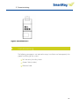
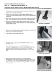
1
1 General Information
SmartRay 9600
User Manual
1
1 General Information
Table of Content
1
2
General Information............................................................................................................... 6
1.1
Symbol Terminology and their Meaning .................................................................. 6
1.2
Storage...................................................................................................................... 6
Laser Safety ............................................................................................................................ 7
2.1
Laser Class 2 / 2M ..................................................................................................... 8
2.2
Laser Class 3R / 3B .................................................................................................... 8
2.3
Laser Specific Regulations ........................................................................................ 9
2.3.1
Laser Class Labelling (Laser Warning Label) ............................................................. 9
2.3.2
Measures to be taken for Laser Class 3B.................................................................. 9
2.3.3
Other Laser Specific Regulations ............................................................................ 10
3
Electrostatic Discharge (ESD) Protection ............................................................................. 11
4
SR9600 Technical Data ......................................................................................................... 12
5
Commissioning ..................................................................................................................... 15
6
5.1
Sensor Installation and Mounting .......................................................................... 16
5.2
Power and Ethernet Cable...................................................................................... 16
5.3
Quadrature Encoder ............................................................................................... 17
5.4
Alive LED ................................................................................................................. 18
5.5
Cable Strain Relief/ bending Radius ....................................................................... 18
5.6
Prepare for Operation/Test for Operational Readiness ......................................... 19
Options/Accessoires ............................................................................................................. 20
6.1
Calibration .............................................................................................................. 20
6.2
Customer-specific Working Distance ..................................................................... 21
6.3
Purging Air Blend with Interchangeable Lenses ..................................................... 21
6.4
Active Air Cooling ................................................................................................... 21
6.5
Band-Pass Filter (increased extraneous light suppression) .................................... 21
6.6
Cable Sets (5 – 10 – 15 – 20m robot cables) .......................................................... 21
6.7
Application Programming Interface (API)............................................................... 22
7
3D-Sensor: Working Principle .............................................................................................. 23
8
Image Data Output ............................................................................................................... 24
8.1
3D Point Cloud Image ............................................................................................. 25
2
1 General Information
8.2
Profile Image........................................................................................................... 26
8.3
Calibrated Profile Image (Z map) ............................................................................ 27
8.4
Intensity Image ....................................................................................................... 28
8.5
Laser Line Width ..................................................................................................... 29
8.6
Live Image ............................................................................................................... 30
9
Maintenance and Care ......................................................................................................... 31
10
Decommissioning & Disposal ............................................................................................... 32
3
Abbildungsverzeichnis
Figure 1: Outer Dimensions 1........................................................................................................... 14
Figure 2: Outer Dimensions 2........................................................................................................... 14
Figure 3: Outer Dimensions 3 .......................................................................................................... 15
4
General Information
The figures in this document are for illustration purpose only.
WARNING
Never dismantle SmartRay GmbH 3D-Sensors
Opening the housing will void the warranty
5
1 General Information
1
General Information
Knowledge of the operating instructions is required for the proper, safe and correct
operation of the 3D-Sensor.
1.1
Symbol Terminology
Terminology and their Meaning
CAUTION
Indicates a potentially hazardous situation. Failure to observe safety
instructions may result in damage to materials or body injury.
Laser Warning
Indicates a potential danger due to laser radiation. Failure to observe safety
instructions may result in serious injury, especially damage to eyesight.
NB
Additional Indication
INFO
Additional Information
1.2
Storage
Store the components in a dry, dust-free environment.
Ensure the following ambient conditions during storage:
Allowed Temperature Range
-20°C to 70°C
6
2 Laser Safety
2
Laser Safety
Due to the intense concentration of the laser beam, the total energy of the beam is
focused onto a small cross-section. Coming into contact with this beam may result
in damage to health. Depending on the laser's wavelength, the beam could even
reach and damage the retina.
According to the potential danger, lasers and devices containing lasers are
arranged into classes in EN 60 825 'Safety of Devices Containing Lasers'.
SmartRay 3D-Sensor devices belong to classes 2, 2M, 3R or 3B.
NB:
You can determine your device's laser class by checking the imprint on the
3D-Sensor or the accompanying documentation.
The laser classes mentioned under 2.1 and 2.2 correspond to the standard DIN EN
60 825-1 (VDE 0837 Part 1) – October 2003 version.
Due to the intense concentration and the associated high power density of the
laser beam, beams from powerful laser devices may be hazardous to your health.
This also applies to reflections from glass surfaces, metal and polished surfaces.
7
2 Laser Safety
2.1
Laser Class 2 / 2M
The available laser beams from Class-2 and 2M lasers fall within the visible
spectrum (400nm to 700nm). Class-2 lasers may be used without any additional
protective measures if it has been determined with certainty that it will not be
necessary to look into the laser beam or its reflection during use intentionally for
longer than 0.25 s (eyelid closure reflex) or repeatedly.
NB:
In the event that a Class-2 laser comes into contact with your eye, close your
eyes and turn away immediately.
Laser devices of Class 2M involve a level of risk that is comparable to Class-2 laser
devices, except when using optical instruments (e.g. magnifying glass or
microscope) which reduce the beam's cross-section.
2.2
Laser Class 3R / 3B
The available laser radiation is in the wavelength range of 302.5 nm to 106 nm and
is hazardous to the eyes, and often for the skin as well (class 3B).
CAUTION
Looking directly into the beam of a Class-3R or 3B laser is dangerous!
Measures and regulations applicable to Class-3B lasers can be found under section
2.3.2 Measures for Laser Class 3B.
8
2 Laser Safety
2.3
Laser Specific Regulations
2.3.1
Laser Class Labelling (Laser Warning Label)
Laser devices ranging within Class 2 and 4 must have a warning label as per section
5.8 of DIN EN 60825-1 indicating the maximum output power of the laser beam,
the output wavelength and where applicable, the pulse duration.
Sample Labels
Class-2M Laser
2.3.2
Class-3B Laser
Measures to be taken for Laser Class 3B
A system with a Class-3B laser must meet the following requirements as per DIN
EN 60825-1:
All directives for the preceding laser classes apply,
Appointment of a laser safety officer is required,
9
2 Laser Safety
An indicator light must be installed for the operating status of the laser,
Remote Control lock,
Key Switch,
Beam Attenuator,
Eye protection (where structural and organisational measures are not
practical).
NB:
NB:
During installation, please do avoid using reflective tools and do not wear or
carry any other reflective objects (e.g. jewellery).
You must also comply with any applicable national regulations and measures not
cited here!
2.3.3
Other Laser Specific
Specific Regulations
In addition to DIN EN 60825-1, the following standards and the employer's liability
insurance association (BG rules) also provide laser-specific regulations:
DIN EN 207
DIN EN 208
DIN EN 12 254
DIN EN 60 825-2
(VDE 0837 Part 2)
DIN EN 60 825-4
DIN EN ISO 11145
BG Rule
Personal eye-protection equipment. Filters and eyeprotectors against laser radiation (laser eye-protectors)
Personal eye-protection. Eye-protectors for adjustment work
on lasers and laser systems (laser adjustment eye-protectors)
Screens for laser working places. Safety requirements and
testing
Safety of laser products. Part 2: Safety of optical fibre
communication systems (OFCS)
Safety of laser products. Part 4: Laser guards
Optics and photonics. Lasers and laser-related equipment.
Vocabulary and symbols
'Einsatz von Augen- und Gesichtsschutz' (Use of eye and
vision protection) (BGR 192)
10
3 Electrostatic Discharge (ESD) Protection
3
Electrostatic Discharge (ESD) Protection
The 3D-Sensors are manufactured and tested in-house by SmartRay for the most
stringent ESD protective measures (as per IEC 61340-5-1). The protective measures
have already been communicated to and implemented by our suppliers.
In order to guarantee an even higher degree of protection, we also inform our
customers here that the 3D-Sensors are delicate electronic components and should
only be installed if all applicable ESD protection measures have been taken.
The 3D-Sensors are shipped in proper ESD packaging. This protects the contents
from static electricity.
CAUTION:
CAUTION :
The original packaging should be used in the case that the 3D-Sensor needs to be
returned.
Recommendations for proper handling:
Employee zones and work zones should be earthed during installation and/or
repair work.
Do not disturb the plug contacts.
11
4 SR9600 Technical Data
4
SR9600 Technical Data
SR9600
SR 9600 Family
3D-Sensor Models
Standard Working Distance
Number of Points per 3D-Profile
3D-Profile Rate
(depends on ROI and exposure time).
Optimal Vertical Field of View
Interfaces
Encoder-Interface
Power Supply
Indicators
Protection Rating
Operating Temperature
Storage Temperature
Weight
Laser
Laser Class
Laser Control
Daylight Filter
SR9628
160 mm
1280
tpy. 15kHz, max. 75 kHz scan rate
±25 mm
Ethernet 100Mbit / Gigabit
4 x inputs 5-24 V (Galvanically Isolated)
2 x outputs 24 V (PNP, Galvanically Isolated)
RS-422 (AB-Channel)
24 VDC ± 10% 0,3 A
LED (green / red)
IP65
0 - 45° Celcius (non-condensing)
-20 bis 70° Celcius
Approx. 2 kg
660 nm bis 15 mW
3B / 2M
Controllable by Software
Controllable over 24 V Input
Ambient Light 10,000 lux
12
4 SR9600 Technical Data
SR9600
Field of View in mm
Lateral Resolution in µm
Vertical Resolution in µm
13
4 SR9600 Technical Data
Figure 1: Outer Dimensions 1
Figure 2: Outer Dimensions 2
14
5 Commissioning
Figure 3: Outer Dimensions 3
5
Commissioning
The following components are required to setup, installation and consequently the
proper functioning of the system:
3D-Sensor by SmartRay GmbH
Power Cable (24 Volts)
Ethernet Cable
15
5 Commissioning
D escription
es cription of Connectors and Sockets:
Sockets :
•
Ethernet Connector
•
5-pin Encoder-Input
•
Connector for 8-pin plug –
power & inputs/outputs
▪
3-pin connector
(customized use)
▪
Alive Signal LED
Sensor Installation and Mounting
5.1
Install the sensor as follows:
•
Use two dowel pins (DIN 6325) on the top side [E
E]
•
Use four M5 screws on the top side [D
D]
The dowel pins serve to secure the head of the 3D-Sensor.
For the dimensions of the attachments, please see the figure in chapter 4.
5.2
Power and Ethernet Cable
C able
The connectors for power [A
A] and Ethernet [B
B] cables should be plugged into the
provided sockets.
.
16
5 Commissioning
Power & I/O 8-pin:
Plug type: Binder 712 No.: 99-0413-00-05
Pin 1
White
0V (24V return)
Pin 2
Brown
+24 Volt
Operating Voltage Operating Voltage +
Pin 3
Pin 4
Green
Yellow
Out 0
Out 1
Maximum 40mA/24V
Maximum 40mA/24V
Grey
Pink
Blue
Red
-
In 0
In 1
In 2
In 3
GND
5.. 24V/max. 10mA
5.. 24V/max. 10mA
5.. 24V/max. 10mA
5.. 24V/max. 10mA
GND
Pin 5
Pin 6
Pin 7
Pin 8
Screen
Indications for inputs and outputs:
Output 0
Usable for freely definable signals.
Output 1
Usable for freely definable signals.
Switches the Laser On / Off:
High: On
Low : Off
Caution!
When powering up the device, the laser is activated
briefly at the low level setting.
From the software, the laser can be deactivated at any
time regardless of the input signal.
Not suitable for laser deactivation for safety purposes
Input 0
Input 1
Input 2
Input 3
5.3
Available for custom use
Unused Inputs must be connected to GND.
Quadrature
Quadrature Encoder
For line lengths ranging over 2 meters you should use a twisted pair electrical connection. The
conductor colors refer to a “standard“ 5-pin lead.
Pin 1
White
A+
Input A +
Pin 2
Brown
A-
Input A -
Pin 3
Black
B+
Input B +
Pin 4
Blue
B-
Input A -
Pin 5
Grey
GND
100kΩ connected to GND
17
5 Commissioning
Inputs conform to RS422 standard!
standard!
The maximum (idle-) voltage between A+/A- respectively B+/B- must not exceed 5 Volts!
Between A+/A- and B+/B-, there is a terminating resistor of 120 Ohm.
5.4
Alive LED
The sensor's LED [A
A] flashes alternating red/ green as soon as the operating
voltage is present.
On successful network connection, the LED flashes more slowly.
In the event of a fault, the LED lights up red continuously.
5.5
Cable Strain
Strain Relief/ bending Radius
The minimum permissible bend radius must be strictly observed! A bend radius
that does not meet the minimum bend radius may result in damage to the cable
and errors in the exchange of signals and data. Damaged cables must be replaced.
Please consult the table below for the typical bend radius to be observed:
Minimum bend radius
Type
Formula
secured in place
freely movable
continuously in
motion
5xd
10 x d
12 x d
(d = diameter)
Minimum bend radius for SmartRay cables
(d =7.8 mm)
39.5 mm
79 mm
94.8 mm
If the cable is in motion continuously (use on robots/shafts), ensure that it is
installed with adequate strain relief to prevent transverse and tensile strain on the
sensor's connector or socket.
18
5 Commissioning
Figure 1: Cable Strain Relief and Bend Radius
5.6
Prepare for Operation/Test for Operational Readiness
1. Connect power and Ethernet cable to the provided sockets on the installed
sensor.
NB:
Power cable should not yet be connected to a power supply.
Ensure adequate strain relief!
2. Connect Ethernet cable to the provided computer.
3. Connect power cable to a power supply.
The Alive LED provides information on whether the sensor is receiving power:
If the LED is flashing, then the sensor is receiving power.
19
6 Options/Accessoires
6
Options/Accessoires
6.1
Calibration
Maximum measurement accuracy thanks to a calibration procedure developed inhouse at SmartRay. All devices are calibrated individually with an array of reference
points in the field of view. This corrects all manner of distortions and other
discrepancies, such as:
•
Perspective distortion
•
Object distortion
•
Laser unevenness (distortion of the laser line)
•
Fabrication tolerances
This enables a high degree of precision in single points of up to 20 µm (depending
on the sensor type). The transformation of the points is carried out in real-time,
which ensures a high frequency of world coordinate points. World coordinates can
be transformed into a Z-map matrix using a special function. This enables
processing of the images with the standard methods of 2D image processing.
20
6 Options/Accessoires
6.2
CustomerCustomer-specific Working Distance
The working distance can be adjusted to the conditions specific to the customer
or application (onsite). This makes it possible to cover different measurement
ranges. For further information, please see the diagrams in section 4.0.
6.3
Purging Air Blend with Interchangeable Lenses
The purging air blend with additional interchangeable lenses enables applications
in heavily contaminated industrial environments. In addition to this, the device is
also protected from particles by an air curtain.
6.4
Active Air Cooling
Enables use of the device in ambient temperatures exceeding 40ºC.
6.5
BandBand-Pass Filter (increased extraneous light suppression)
The band-pass filter increases the sensor's sensitivity to extraneous light compared
to the daylight filter standardly built in.
6.6
Cable Sets (5 – 10 – 15 – 20m robot cables)
Power I/O cable
Standard model:
Order number: 6.310.0XX
(XX is the cable length in metres)
Suitable for robots/cable handlers (silicon-free and halogen-free):
Order number: 6.304.0XX
(XX is the cable length in metres)
Ethernet/network cable:
21
6 Options/Accessoires
Standard model:
Order number: 6.300.0XX
(XX is the cable length in metres)
Suitable for robots/cable handlers (silicon-free and halogen-free):
Order number: 6.305.0XX
(XX is the cable length in metres)
6.7
Application Programming Interface (API)
The API interface makes it possible to link SmartRay 3D-Sensors with Windowsbased and Linux-based programs.
Only a few basic API functions are needed for the main functionality. For a detailed
description of the functions, please see the additional documentation on the
SmartRay API.
NB: If working with customized image processing libraries, please contact your
SmartRay representative.
22
7 3D-Sensor: Working Principle
7
3D-Sensor: Working Principle
SmartRay 3D-Sensors are based on the principle of laser triangulation. In laser
triangulation, a laser point or a laser line is projected onto the object from one
direction, while the object will be observed from another direction.
As the distance between the camera and laser and the angle between laser beam
and direction of observation is known, the distance to the illuminated point/line
on the object can be calculated.
Figure 2: laser triangulation
1
Due to the recording procedure, the surface effects (colour, reflection ratio, etc.)
will have a minimal impact on topographic identification.
1
reference: Internet; Wikipedia – Abstandsmessung (optisch);
http://de.wikipedia.org/wiki/Abstandsmessung_(optisch)
23
8 Image Data Output
8
Image Data Output
The 3D-Sensors are synonymous to laser scanners or profile sensors, and record
scenes similar to a line-scan camera or a flatbed scanner, rather than full-surface
scenes. For a full-surface recording, some relative movement between the scanner
and object (robot, axis or assembly line) is required.
3D-Sensors from SmartRay provide the following image information:
•
•
•
•
•
3D-Profile
Point Cloud
Laser Line Intensity
Laser Line Thickness
Live Image (For setup & debug)
The various image types allow for different approaches. 3D images contain height
information, while 2D images can be consulted for texture analysis. It is also
possible to work in Mixed Mode: if the 3D information provides insufficient contrast,
because for example the height differences are not provided, the necessary
information can be extracted from the 2D intensity image or the image with the line
widths. Imprints or surface information can also be revealed by the intensity image.
This is illustrated by the following figures:
Laser Line Intensity Map
Point Cloud
All image types are created simultaneously. The 2D intensity image and line widths
correspond to the 3D data, and further matching is not required.
See SR Studio / API documentation for more detailed information on the
construction of the image data.
24
8 Image Data Output
8.1
3D Point Cloud Image
Near the sensor
Further from the sensor
The scanner provides 3D coordinates in x, y, z. The coordinates are metric and
relate to the sensor's point of origin. The point of origin is the nominal clearance to
the sensor and is centred to the sensor and the laser line (midview).
• X = Coordinates in the direction of travel (obtained by forward-motion stroke
synchronised to movements)
• Y = Coordinates along the laser line
• Z = Distance to the sensor (the higher this is, the nearer the sensor)
The point cloud is based on sensor calibration, which is available in various
accuracy variations.
25
8 Image Data Output
8.2
Profile Image
The intensity values represent the height information in 14bit (16384 height levels) in camera
coordinates. These are not calibrated and are subject to the optical features of the scanner
(perspective and distortion).
Higher values are contour points that lie closer to the sensor. 0 is the minimum value (farfield visual range) and 16383 is the maximum value (near-field visual range). Please note that
this refers to the description of the values range. The actual measurement range of the sensor
depends primarily on the depth of focus of the laser line and can be obtained from the data
sheet of the respective sensor type.
The following images show the height image and the profile section from the height image
(along the red line):
26
8 Image Data Output
8.3
Calibrated Profile Image (Z map)
In contrast to the non-calibrated profile image, the Z map consists of metric
coordinates. The world coordinates (point cloud) are mapped in a matrix image. The
height resolution and lateral resolution are defined over the API sensor's
"Remapper" function.
The 2D image processing methods can be applied to the matrix image. A standard
BV library can be used. It can also be used for actual measurement tasks.
The point cloud is based on sensor calibration, which is available in various
accuracy variations.
27
8 Image Data Output
8.4
Intensity Image
The intensity image is obtained from the brightness information of the laser line. It
is similar to recording with a line-scan camera, the difference being that the
intensity along the object contour is recorded. The pixels correspond to the
scanner's 3D coordinates without requiring special matching.
!
Important information for the image processor:
Together with the remapper functionality, the scanner creates an image that
corresponds to a telecentric line-scan camera with high depth focus! The impact of
both the perspective and the lens distortion is eliminated by the camera calibration.
The following images show the image intensity and grey-tone development along a
line from the intensity image:
28
8 Image Data Output
8.5
Laser Line Width
The laser line width can also be displayed in image form. Every pixel value
represents the width of the laser line at that particular point.
This method results in contrasts where the laser line scatters as a result of
corresponding surface treatment or applications to the surface (e.g. transparent
adhesive).
Note:
The average or standardised brightness may be calculated by setting the intensity
image against the laser line width.
29
8 Image Data Output
8.6
Live Image
The live image shows the actual image of the scene currently being viewed by the
scanner and from which the most recent profile section has been obtained.
The live image is a useful tool for setting up or assembling the system. In addition,
seeing a live image of what the sensor is seeing is a great benefit for arranging a
robot path.
It also helps trained image processors to assess recorded scenes with regard to
reflections (see image), shading or differences in intensity.
30
9 Maintenance and Care
9
Maintenance and Care
Deposits such as dirt, dust, etc. on the viewing window of the 3D-Sensor may
affect the quality of the measurements. For this reason, regular cleaning is
recommended.
The glasses should be cleaned using a microfiber cloth and, if applicable, with
alcohol.
WARNING
WARNING:
NING:
Before beginning maintenance work, disconnect the sensor from the
power supply!
31
10 Decommissioning & Disposal
10
Decommissioning & Disposal
Before demounting or uninstalling the 3D-Sensor, disconnect it from the power
supply! Unattach all connected cables from the 3D-sensor.
Dispose the components properly or send them to:
Shipping Address
SmartRay GmbH
Buergermeister-Finsterwalder-Ring 14
D-82515 Wolfratshausen,
Germany
Service & Repairs
In cases of defects related to the 3D-Sensor (body, cables), please return the
defective product for replacement or repairs.
Before demounting or uninstalling the 3D-Sensor, disconnect it from the power
supply!
CAUTION:
The original packaging should be used to return the sensor!
Shipping Address
SmartRay GmbH
Buergermeister-Finsterwalder-Ring 14
D-82515 Wolfratshausen,
Germany
Phone:
+49 (0) 8171 9683400 Fax:
+49 (0) 8171 9683 401
[email protected]
www.smartray.de
32