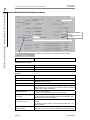
1
User manual COM-SIPOS PC parameterization program for SIPOS 5 actuators Software for: - Commissioning - Parameterization - Operation - Diagnosis - Maintenance - Visualization Issue 01.15 Subject to change without notice! Y070.024/GB User manual COM-SIPOS Contents Contents Contents ...................................................... 2 7 Tab sheets for parameters and current values ............................... 29 7.1 Actuator info ................................... 30 1 General remarks .............................. 3 2 Installation and program start ....... 4 7.2 Valve spec. ..................................... 31 2.1 Scope of delivery .............................. 4 7.3 Input/Output .................................... 33 2.2 System requirements ........................ 4 7.4 Security........................................... 36 2.3 Installation ......................................... 6 7.5 Bus / Other ..................................... 38 2.4 Start COM-SIPOS ............................. 7 7.6 Options ........................................... 41 2.5 2.5.1 2.5.2 2.5.3 Establish connection ......................... 7 via null modem cable ........................ 8 via computer cable ............................ 8 via Bluetooth ..................................... 9 7.7 Torque curve .................................. 44 7.8 C+M (Control and Monitoring) ........ 46 7.9 Diagnosis ........................................ 49 2.6 Uninstall COM-SIPOS ....................... 9 7.10 State of bus .................................... 50 3 Reading and writing parameters . 10 7.11 State of unit .................................... 53 3.1 Read actuator parameters .............. 11 8 Checking the interface to DCS .... 58 8.1 Start simulation ............................... 58 8.2 Simulation mode for conventional DCS ................................................ 59 8.3 Simulation mode for PROFIBUS .... 60 9 Convert *.ste into *.txt .................. 61 10 Example: Printout of actuator state ............................................... 63 3.2 Write new/changed actuator parameters ...................................... 13 3.2.1 to the actuator ................................. 13 3.2.2 to the replacement electronics ........ 13 4 Update firmware ............................ 14 4.1 via Bluetooth for PROFITRON and HiMod (from firmware 2.61) ............ 15 4.2 for PROFITRON and HiMod (from firmware 2.40/2.53) ......................... 16 4.2.1 with computer cable ........................ 16 4.2.2 with null modem cable..................... 17 4.3 for actuators delivered from 2004 ... 18 4.4 for actuators delivered until 2003 .... 19 5 Menus............................................. 20 5.1 File .................................................. 20 5.2 Edit .................................................. 21 5.3 View ................................................ 21 5.4 Actuator........................................... 22 5.5 Interface .......................................... 25 5.6 DE/EN/CZ/PL/CN/RU...................... 27 5.7 ”?“ (help) ......................................... 27 6 Direct commands via symbols .... 28 Page 2 Y070.024/GB User manual COM-SIPOS 1 General remarks 1 General remarks COM-SIPOS was originally designed as a software tool for commissioning and trouble-shooting the SIPOS 5 electric actuator range. The software is subject to permanent development to implement the continuously enhanced features of the SIPOS 5 actuator range and to meet the increasing requirements of COM-SIPOS users. Meanwhile, COM-SIPOS has evolved into a software for commissioning, parameterization, operation, diagnosis, maintenance, trouble-shooting, and visualization. For the PROFITRON/HiMod, all visualized parameters in COM-SIPOS can also be set / viewed via the local push buttons and the LCD. The ECOTRON has limited programming abilities both locally and via COM-SIPOS. Fig.: COM-SIPOS start screen There are dangerous high voltage levels inside the actuator. During communication, the cover of the electronics unit has to be removed, if required, depending on type and version. Avoid touching tracks or components on the boards with the fingers and prevent tracks or components coming into contact with metal objects. By consulting the person responsible for the plant, obtain an assurance or establish that unintentional startup of the equipment cannot cause a disturbance in the plant or injury to persons. If a cut-off mode has been selected that is not appropriate for the valve, damage to the valve may result! Highly sensitive CMOS semiconductor components are mounted on the printed circuit boards which are extremely sensitive to static electricity. Avoid touching tracks or components on the boards with the fingers and prevent tracks or components coming into contact with metal objects. This manual is only complete in combination with the instruction manual of the respective actuator: ECOTRON Y070.019/GB, PROFITRON/HiMod Y070.020/GB. Y070.024/GB Page 3 General remarks 1 User manual COM-SIPOS 2 Installation and program start 2 Installation and program start 2 Installation and program start 2.1 Scope of delivery For communication connection on the control board, i.e. no lead through, external COM-SIPOS connection and no Bluetooth interface (cover of the electronics unit must be opened!). Order no.: 2SX5100-3PC02 (Fig. 1) ■ "COM-SIPOS PC parameterization program“ installation CD, ■ 9-pole Sub-D null modem cable and ■ USB serial adapter, incl. installation CD. Fig. 1: Scope of delivery For communication via lead through external COM-SIPOS connection or with Bluetooth, (cover of the electronics unit must not be opened!). This affects HiMod versions and actuators ordered with add. versions "S38“, "C50“ or "C51“. Order no.: 2SX5100-3PC05 ■ "COM-SIPOS PC parameterization program“ installation CD. 2.2 System requirements Hardware: ■ ■ ■ ■ Pentium 100 MHz, COM port or USB port, CD-ROM drive At least 5 MB of available hard-disk capacity 9-pin Sub-D null modem cable and USB adapter, if required (included in the scope of delivery) * 9 pin Sub-D RS232 computer cable (if the actuator is equipped with the external COM-SIPOS connection) * ■ Bluetooth adapter (if actuator is equipped with Bluetooth interface) * * also available as accessory part (see below!) Operating System: Windows XP, Windows 7, etc. For communication with COM-SIPOS via serial interface RS232 (9-pin Sub-D null modem cable or 9 pin Sub-D RS232 computer cable) only laptops and neither PCs nor programming devices with mains connection must be used! Page 4 Y070.024/GB 2 Installation and program start 2 Accessories: ■ Null modem cable with USB adapter (Fig. 2) for connection to the RS232 or USB port of the laptop. Order no.: 2SX5100-3PC01 (already included in the "PC parameterization program COM-SIPOS" standard package, order no. 2SX51003PC02!) Fig. 2: Null modem cable with USB adapter The serial USB adapter can also be ordered individually. Order no.: 2SX5100-3PC07. ■ 9 pin Sub-D RS232 computer cable (Fig. 3) for connection via external COM-SIPOS connection, i.e. if the actuator is equipped with a lead through round plug connector at the electrical connection (see chapter 2.5.2). Required for HiMod without Bluetooth interface and actuators order with add. version "S38“. Order no.: 2SX5100-3PC06 ■ Bluetooth adapter (Fig. 4) for wireless communication with the actuator integrated Bluetooth interface. Required if the actuator was ordered with add. version "C50“ or ”C51”. Order no.: 2SX5100-3PC08 ■ Bootstrap adapter (Fig. 5) for connection to the RS232 interface. The bootstrap adapter is exclusively used for firmware updates for actuators delivered until the end of 2003, i.e. for actuators not yet equipped with a bootstrap slider and a reset push button on the control board (see chapter 2.5.1). Order no.: 2SX5100-3PC03 ■ PROFIBUS Master simulator (Fig. 6) for connection to the RS 485 interface (PROFIBUS connector) of a PROFIBUS participant. The PROFIBUS master simulator can be used in COM-SIPOS to select the desired participant (actuator) via PROFIBUS address, download and change the actuator parameters and save them to the actuator and perform processes if the MASTER slave (communication to the DCS) is deactivated. Order no.: 2SX5100-3PC04 Y070.024/GB Fig. 3: 9 pin Sub-D RS232 computer cable Fig. 4: Bluetooth adapter Fig. 5: Bootstrap adapter Fig. 6: PROFIBUS Master simulator Page 5 Installation and program start User manual COM-SIPOS 2 Installation and program start User manual COM-SIPOS 2 Installation and program start 2.3 Installation Insert the CD into the CD-ROM drive. The installation either starts automatically or by doubleclicking the “Setup COM-SIPOS Flash.exe“ file on the CD. Click on “Select Language“ first to select the user interface language of the installation program. If previous COM-SIPOS versions are installed, this information will be displayed in the next window. Click on the “Yes“ button to start the recommended de-installation of the former version(s) found on the computer. To delete these versions, simply acknowledge the following confirmation in English. When the “Uninstall successfully completed“ or “Uninstall completed. Some elements…“ message appears, click “OK” to close “Remove Program From Your Computer“ window. The uninstall routine is displayed for each former COM-SIPOS version found. Recommendation: Have all former versions removed. The actuator parameter files (extension: *.ste) contained in the former program directories “Setup COM-SIPOS Flash German“ or “Setup COM-SIPOS Flash English“ are retained in the stored directory! COM-SIPOS Flash directories without actuator parameter files are completely deleted. The actual installation of the current program version starts now Click “Next“ button Read and confirm “License Agreement“ with “I Agree“ “ReadMe File“, among others with the features of the new version. Click “Next“ to get to the next step, “Destination Location“: Default setting for the target directory is: “C:\Program Files (x86)\COM-SIPOS Flash“. Click "Next" to open the "Select Components" window. Select by clicking the check box. The selected component will be installed. The available components were verified by SIPOS Aktorik and are safe. Ignore subsequent information by clicking "Continue installation"! In the following window, click “Next“ to start the actual copying procedure which is shortly displayed in another window. “Finish“ in the last window completes the installation. Page 6 Y070.024/GB User manual COM-SIPOS 2 Installation and program start 2 Start COM-SIPOS Installation and program start 2.4 Due to the installation, 3 links for starting the program were created (from version 2.12): ■ Icon (Fig., item 1) on the desktop, ■ Short-cut under ”Start All Programs“ (Fig., item 2) and ■ as main entry under “Start All Programs COM-SIPOS Flash“ (Fig., item 3). Fig.: Start COM-SIPOS The user manuals in the available languages as well as “Uninstall COM-SIPOS Flash“ to remove the software from your laptop can be found under “Start\All Programs\COM-SIPOS Flash“. After clicking one of the start options, the standard COM-SIPOS user interface will appear. The default language is that of the operating system (if COM-SIPOS does not support the language of the operating system, English is set as default). The setting of a different program language is described in chapter 5.6. 2.5 Establish connection Depending on the version, there are three options for connecting the actuator to the laptop: ■ Standard connection via null modem cable Connect the null modem cable to the RS232 interface on the control board while the electronics housing is open, see chapter 2.5.1. ■ Connection via external COM-SIPOS connection Connect the 9-pin Sub-D RS232 computer cable to the round plug connector at the electrical connection, see chapter 2.5.2. ■ Connection with Bluetooth The communication is wireless via the Bluetooth interface integrated in the actuator, see chapter 2.5.3. Avoid any electrostatic discharge (ESD) to any electronic part inside the SIPOS 5 while the electronics housing is open. Any ESD may damage some highly sensitive CMOS devices. Do not touch any electronic part with your hands or metallic tools! For communication via serial interface RS232 (9-pin Sub-D null modem cable or 9 pin Sub-D RS232 computer cable) only laptops and neither PCs nor programming devices with mains connection must be used! Y070.024/GB Page 7 User manual COM-SIPOS 2 Installation and program start 2 Installation and program start 2.5.1 via null modem cable To install the cable between laptop and SIPOS 5 actuator, open the cover of the local control unit of the actuator which is fastened with screws. Connect the 9-pin plug of the null modem cable to the 9-pin interface plug (SUB-D socket) inside the actuator. This plug is located on the control PCB, see Fig. 1 and 2. Only use the null modem cable that is supplied with the software. Any damage on the actuator electronics caused by using wrong cables will void warranty! Fig. 1: Control PCB ECOTRON In case the computer used has no serial COM port but a USB port, a USB to serial adapter must be used. After installation of the adapter, please double-check the COMport of the USB adapter. This can be done under ”Start Control Panel All Control Panel Items Device Manager Ports“. Actuators delivered from Jan. 2004 are equipped with an integrated bootstrap slide and RESET button and can be connected to a standard null modem cable, see Fig. 3! Actuators delivered until Dec. 2003, see Fig. 4, have to be connected to a special null modem cable, which has the following wiring (only pins 2, 3 and 5)! PC Fig. 2: Control PCB PROFITRON Fig. 3: Control PCB with RESET button SIPOS RxD 2 2 RxD TxD 3 3 TxD Fig. 4: Control PCB without GND 2.5.2 5 5 GND RESET button via computer cable For actuators with an external COM-SIPOS connection, the RS232 interface is located in a dust and water tight round plug connector with quick disconnect coupling (9-pin Sub-D) on the electrical connection, see Fig. 5. Remove the protective cap of the round plug connector on the actuator to fit the computer cable between laptop and the SIPOS 5 actuator. The cap is provided with a plastic band for retention. Connect the round plug of the computer cable to the round plug connector at the actuator connection. Fig. 5: External COM-SIPOS interface Page 8 Y070.024/GB User manual COM-SIPOS 2 via Bluetooth Actuators equipped with Bluetooth interface are ready for operation on delivery (sliding switch in position “ON“). This is indicated by the illuminated blue LED after the mains voltage has been supplied. For wireless communication with the actuator, a Bluetooth adapter must be connected to the USB port of the laptop, PC or programming device and the Bluetooth adapter installation (driver and application) must be completed. Each Bluetooth device (slave) has a definite Bluetooth address for clear identification. In addition, each Bluetooth device is assigned a device name for easier selection. As a standard, this name consists of the plant identification number - if available - and the 9 digit works number. Any connection to the actuator is indicated by the flashing white LED, perfectly visible from the distance. 1 LED (blue): Bluetooth activated 2 Sliding switch: ON OFF 3 LED (white flashing): Bluetooth connection to actuator is implemented Fig.: Bluetooth PCB The Bluetooth function can be switched off via the ON/OFF sliding switch on the Bluetooth PCB! Bluetooth is supported as from firmware version 2.39! Direct firmware update via Bluetooth is possible for firmware version 2.61 and later! Enter the password “9044“ to establish connection! 2.6 Uninstall COM-SIPOS Uninstalling COM-SIPOS Flash (from version 2.12): ”Start All Programs COM-SIPOS Flash Uninstall COM-SIPOS Flash” Use the “Uninstall COM-SIPOS Flash“ command under ”Start\All Programs\COM-SIPOS Flash“ to remove the software again: Select Uninstall Method “Automatic“, then “Next“ to get to the next window and select “Finish“ to perform the uninstall procedure. Always select this method to remove the COM-SIPOS PC parameterization program, otherwise it cannot be ensured that all actuator parameter files, which were saved via COM-SIPOS in the respective directory, are retained. Y070.024/GB Page 9 Installation and program start 2.5.3 2 Installation and program start User manual COM-SIPOS 3 Reading and writing parameters 3 Reading and writing parameters 3 Reading and writing parameters Read (download) and write (upload) of parameters Actuator parameters How to … Display Change Save Description perform steps The actuator parameters are displayed in the tab sheets. After download of the parameters, it is possible to change them depending on the actuator type. All actuator parameters (customer and factory parameters), which include end position adjustment and operational data, can be saved in a file (2 kB). We strongly recommend saving the actuator parameter files after successful commissioning for documentation and reference purposes (especially in case of an electronics replacement). Duplicate This function is extremely helpful when installing a replacement electronics or a new control PCB, since all originally programmed customer and factory parameters including end position adjustments are uploaded into the replacement unit. This results in an identical copy of the replaced unit and makes recommissioning obsolete after the replacement. Print The printed actuator parameters can be used for documentation purposes. Send The saved actuator parameters can be sent for evaluation as attachment to [email protected] . Trouble shooting How to … Description perform steps Display diagnosis This data is displayed in the tab sheets ”Diagnosis”, “State of bus“ and “State of Unit”. and fault messages In case possible faults cannot be resolved, please save the actuator parameters and send them to [email protected] . Firmware-Update How to … Update Description perform steps The installed firmware version is displayed in the tab sheet “Actuator info”. The current firmware version and a history table can be found on our website www.sipos.de. Page 10 Y070.024/GB User manual COM-SIPOS 3 Reading and writing parameters Check wiring How to … Description perform steps Actuator outputs DCS inputs The wiring to the process control system can be checked independent of the actuator status. DCS outputs Actuator inputs The correct transmission of binary and analog control system output signals to the actuator as well as the fieldbus status of the actuator can be checked on the ”C+M“tab. Steps: 3.1 Read (download) actuator parameters << see chapter 3.1 >> Display/change parameters on tab sheets << see chapter 7 >> Write (upload) new/changed actuator parameters << see chapter 3.2 >> Save downloaded actuator parameter file << see chapter 5.1 >> Print a summary of actuator settings and diagnosis data. Example, see chapter 10. << see chapter 5.1 >> Display diagnosis and state of unit data << see chapter 7.9, 7.10 and 7.11 >> Update firmware << see chapter 4 >> Check interface to the control system (DCS inputs) << see chapter 8 >> Check the DCS outputs (actuator inputs) << see chapter 7.8 >> Read actuator parameters The data of the SIPOS 5 actuators can be downloaded for various purposes: ■ Trouble shooting ■ Documentation ■ Availability of data in case of replacement of the electronics or the control PCB available. Therefore we strongly recommend downloading and saving the actuator parameters after successful commissioning! All actuator parameters, including the end position adjustment, can then be uploaded to replacement electronics. Provided that the gear unit was not disconnected from the valve, recommissioning after performing the replacement is not required! Y070.024/GB Page 11 Reading and writing parameters 3 User manual COM-SIPOS 3 Reading and writing parameters 3 Reading and writing parameters Procedure: (Steps 1 and 2 are not required for Bluetooth applications.) 1. Remove the cover of the electronics unit (not for external COM-SIPOS connection). 2. Connect null modem cable or computer cable to actuator serial interface (see chapter 2.5). If reading is to be performed via null modem cable despite available Bluetooth interface, set Bluetooth slider to "OFF“ (see chapter 2.5.3)! 3. Start COM-SIPOS (see chapter 2.4). 4. If necessary, select the correct interface, see Fig. 1 and 2 (see also chapter 5.5). The set interface is stored until the next change (from COM-SIPOS version 2.12). Fig. 1: Menu Interface Fig. 2: Select serial interface 5. Read (download) actuator parameters (see Fig. 3). ”Read parameter“contains all actuator parameters, i.e. both factory parameters and customer parameters which can be changed using COM-SIPOS, including end position adjustments and operational data. Fig. 3: Reading of actuator parameters 6. Define storage procedure (see Fig. 4). Name, revision history as well as storage location of an actuator parameter file (*.ste) can be preset via "Settings STE-file“, see also chapter 5.1 The settings remain stored until next revision! New STE-files are stored with ´"Save“ in the preset folder with the set file name. If the STE-file setting is changed once again during an application, restart COMSIPOS for activation! Fig. 4: Preset *.STE-files 7. Save actuator parameters (see fig. 5). The created file has an “.ste” extension. The size is only a few bytes, ideal for sending via e-mail! Select "Save As“, if no presetting was made, via "Setting STE-file“! Page 12 Fig. 5: Save actuator parameters Y070.024/GB User manual COM-SIPOS 3 Reading and writing parameters 3.2 Write new/changed actuator parameters 3.2.1 to the actuator If the customer parameters (e.g. tripping torque, output speed, etc.) were changed after reading out the actuator parameters using COM-SIPOS and if these changes are to become effective, perform an upload via ”Actuator“ menu, "Write parameter" menu item, see Fig. 1. 3.2.2 Fig. 1: Save changed parameters to the replacement electronics The following procedure has proved extremely useful when installing a replacement electronics unit since all actuator parameters read and stored from the original actuator (customer and factory parameters including end position adjustment and operational data) are uploaded to the new replacement part. This results in an identical copy of the replaced unit. Recommissioning after replacing a part would only be required if the gear unit of the actuator was also disconnected from the valve. Procedure: (Steps 1 and 2 are not required for Bluetooth applications.) 1. Remove the cover of the electronics unit (not for external COM-SIPOS connection). 2. Connect null modem cable or computer cable to actuator serial interface (see chapter 2.5). If reading is to be performed via null modem cable despite available Bluetooth interface, set Bluetooth slider to "OFF“ (see chapter 2.5.3)! 3. Start COM-SIPOS (see chapter 2.4). 4. If necessary, select the correct interface (see chapter 5.5). 5. Open actuator parameter file (*.ste) of the original actuator in COM-SIPOS, see Fig. 2 and 3. Fig. 2: Open STE-files For ECOTRON, the DIP switches and potentiometers must be set in accordance with the settings of the opened STE-file and confirmed with ON OFF at DIP switch S8! Fig. 3: Select actuator parameter file 6. Write to replacement electronics. Upload complete actuator parameters via "Actuator“ menu, "Factory parameter“ submenu, "Write EEPROM parameter“ menu item, see Fig. 4. For further information, please refer to the mounting instructions for replacement electronics Y070.073/GB! Fig. 4: Write actuator parameters Y070.024/GB Page 13 Reading and writing parameters 3 User manual COM-SIPOS 4 Update firmware 4 Update firmware 4 Update firmware A firmware update is performed via the ”Actuator” menu, see Fig. Firmware updates can always be performed even if the actuator parameters were not read (downloaded) previously! Depending on the version ECOTRON, PROFITRON or HiMod and the delivery date as well as the firmware installed in the actuator and the availability of a Bluetooth interface, different options for uploading new firmware exist, refer to table below! The current firmware version, e.g. PR_V266c.bin for PROFITRON and HiMod, or EC_V266c.bin for ECOTRON Fig.: Firmware upload as well as a history overview are available on our website (www.sipos.de)! During firmware update, the communication to the DCS is interrupted! Version Delivery date or installed firmware (FW) Bluetooth interface Firmware upload direct Bluetooth… Firmware upload direct… Firmware upload… Firmware update, see chapter … HiMod from FW 2.61 until FW 2.60 PROFITRON from FW 2.61 from FW 2.40 / 2.53 ECOTRON yes 4.1 4.2 yes yes 4.3 4.1 yes 4.2 4.3 from 2004 until 2003 from 2004 until 2003 4.4 4.3 4.4 Procedure: 1. If necessary, select the correct interface (see chapter 5.5). 2. Select option for firmware update. Select menu item for firmware update in the "Actuator“ menu: ■ ”Firmware upload direct Bluetooth“ Select "Firmware upload direct Bluetooth“ menu item for PROFITRON and HiMod with Bluetooth interface from firmware version 2.61. Continue with chapter 4.1 ■ ”Firmware upload direct Bluetooth“ Select "Firmware upload direct Bluetooth“ menu item for PROFITRON and HiMod with Bluetooth interface from firmware version 2.40 or 2.53. Continue with chapter 4.2 ■ ”Firmware upload“ Select "Firmware upload“ menu item: - for ECOTRON, - for PROFITRON with firmware version up to 2.39 and - if upload with was either interrupted with "Firmware upload direct…“ or "Firmware upload direct Bluetooth“. For delivery date from Jan. 2004, continue with chapter 4.3 For delivery date up to Dec. 2003, continue with chapter 4.4 Page 14 Y070.024/GB User manual COM-SIPOS 4 Update firmware 4.1 via Bluetooth for PROFITRON and HiMod (from firmware 2.61) A direct firmware upload via Bluetooth is only available for PROFITRON/HiMod actuators with Bluetooth interface as well as firmware version 2.61 and higher. Procedure: 1. Connect Bluetooth adapter to USB port at laptop, PC or programming device. Correct installation of the Bluetooth adapter (drive and application) on this laptop, PC or programming device must be complete. 2. Select "Firmware upload direct Bluetooth“ command in the "Actuator“ menu, click File button and select desired firmware, e.g. PR_V266c.bin for PROFITRON and HiMod actuators, see Fig. The desired firmware must be located in a directory which can be accessed via laptop, PC or programming device! 3. Click Start button in the dialog window (Start button is locked for the duration of the data transfer). Available firmware version in the actuator (FW 2.61 and higher) is checked. The firmware upload will be aborted if the firmware version is not correct! Fig.: Upload firmware via Bluetooth Transmission of the new firmware is displayed with the progress bar and may take several minutes (approx. 10 – 15 min). The new firmware is automatically started after the report „Successfully done“ in the text window. 4. Close button closes the dialog box. After the firmware is uploaded to the actuator, the current parameters can be downloaded with Actuator Read parameter. The firmware version is displayed in the “Actuator info” tab sheet. If the direct firmware update is aborted (power supply of the actuator is switched off, Bluetooth connection aborted, firmware requirement is not met …), the firmware was not or only partially loaded to the actuator! In this case, upload the new firmware version once again according to chapter 4.3. ”for actuators, delivered from 2004“. Otherwise the actuator is not operable! Y070.024/GB Page 15 Update firmware 4 4 Update firmware User manual COM-SIPOS 4 Update firmware 4.2 for PROFITRON and HiMod (from firmware 2.40/2.53) A direct firmware upload is only available for PROFITRON/HiMod actuators with firmware version 2.40 or 2.53 and higher. If the actuator has an external COM-SIPOS connection (HiMod without Bluetooth interface and for actuators ordered with add.version "S38“), you only have to connect the 9-pin Sub-D RS232 computer cable with quick disconnect coupling to the round plug connector on the electronics housing. The housing does no longer have to be opened. If the actuator does not have an external COM-SIPOS connection, the electronics housing must be opened and the new firmware uploaded using the null modem cable. 4.2.1 with computer cable Procedure: 1. Remove protective cap of the 9-pin SUB-D round plug connector on the electrical connection. 2. Connect computer cable (9-pin Sub-D RS232) with quick disconnect coupling to the 9-pin SUB-D round plug connector at actuator and the serial interface/USB port (using a USB serial adapter) to the laptop. 3. Select the "Firmware upload direct“ command in the "Actuator" menu, press File button and select desired firmware, e.g. PR_V266c.bin for PROFITRON and HiMod actuators, see Fig. The desired firmware must be located in a directory which can be accessed via laptop! 4. Click Start button in the dialog window (Start button is locked for the duration of the data transfer). Available firmware version in the actuator (FW 2.40 or 2.53 and higher) is checked. The firmware upload will be aborted if the firmware version is not correct! Fig.: Upload firmware via PC cable Transmission of the new firmware is shown in the progress bar. The new firmware is automatically started after the report „Successfully done“ in the text window. 5. Close button closes the dialog window. 6. Disconnect quick-disconnect coupling, remove computer cable and fit protective cap. After the firmware is uploaded to the actuator, the current parameters can be downloaded with Actuator Read parameter. The firmware version is displayed in the “Actuator info” tab sheet. If the direct firmware update is aborted (power supply of the actuator is switched off, computer cable is disconnected, firmware requirement is not met …), the firmware was not or only partially loaded to the actuator! In this case, upload the new firmware version once again according to chapter 4.3. ”for actuators, delivered from 2004“. Otherwise the actuator is not operable! An existing cable connection via computer cable does not have to be changed! Page 16 Y070.024/GB User manual COM-SIPOS 4 with null modem cable Procedure: 1. Remove the cover of the electronics unit. 2. In case a Bluetooth interface is available, push sliding switch to OFF (see chapter 2.5.3). 3. Connect null modem cable to the SUB-D socket on the control PCB of the actuator and to the serial interface/ USB port (via USB to serial adapter) of the laptop. 4. Select „Firmware upload direct“ command in the "Actuator“ menu, click File button and select desired firmware, e.g. PR_V266c.bin for PROFITRON and HiMod actuators, see Fig. The desired firmware must be located in a directory which can be accessed via laptop! 5. Click Start button in the dialog window (Start button is locked for the duration of the data transfer). Available firmware version in the actuator (FW 2.40 or 2.53 and higher) is checked. The firmware upload will be aborted if the firmware version is not correct! Fig.: Upload firmware with null modem cable Transmission of the new firmware is shown in the progress bar. The new firmware is automatically started after the report ”Successfully done“ in the text window. 6. Close button closes the dialog window. 7. Disconnect null modem cable. 8. In case a Bluetooth interface is available, push sliding switch back to ON. 9. Fit the cover of the electronics housing with screws. After the firmware is uploaded to the actuator, the current parameters can be downloaded with Actuator Read parameter. The firmware version is displayed in the “Actuator info” tab sheet. If the direct firmware update is aborted (power supply of the actuator is switched off, null modem cable is disconnected, firmware requirement is not met …), the firmware was not or only partially loaded to the actuator! In this case, upload the new firmware version once again according to chapter 4.3. ”for actuators, delivered from 2004“. Otherwise the actuator is not operable! An existing cable connection via null modem cable does not have to be changed! Y070.024/GB Page 17 Update firmware 4.2.2 4 Update firmware User manual COM-SIPOS 4 Update firmware 4 Update firmware 4.3 for actuators delivered from 2004 Procedure: 1. Remove the cover of the electronics unit. 2. In case a Bluetooth interface is available, push sliding switch to OFF (see chapter 2.5.3). 3. Connect null modem cable to the SUB-D socket on the control PCB of the actuator or, for an external COM-SIPOS connection, the computer cable (9-pin Sub-D RS232) with quick disconnect coupling to the 9-pin Sub-D round plug connector and to the serial interface/ USB port (via USB to serial adapter) of the laptop. 4. Slide Bootstrap slider to the right in direction "BOOT“, see Fig. 1. 5. Select "Firmware upload“ command in the "Actuator“ menu, click File button and select desired firmware, e.g. PR_V266c.bin for PROFITRON and HiMod actuators or EC_V266c.bin for ECOTRON, see Fig. 2. The desired firmware must be located in a directory which can be accessed via laptop! Fig. 1: Slider ( BOOT) and RESET push button 6. Click Start button in the dialog window (Start button is locked for the duration of the data transfer). 7. Press RESET push button, see Fig. 1. Transmission of the new firmware is shown in the progress bar. The new firmware is automatically started after the report “Ready” in the text window. 8. Slide Bootstrap slider to the left to initial position Fig. 2: Upload firmware After a firmware update the bootstrap slider has to be moved in OFF position (= away from “BOOT”) again. Otherwise the control PCB will stall in BOOT mode with next power-up! If this happens, move bootstrap slider to the left in OFF position and push RESET again! 9. Close button closes the dialog window. 10. Disconnect null modem cable or PC cable. 11. In case a Bluetooth interface is available, push sliding switch back to ON. 12. Fit the cover of the electronics housing with screws. After the firmware is uploaded to the actuator, the current parameters can be downloaded with Actuator Read parameter. The firmware version is displayed in the “Actuator info” tab sheet. If the direct firmware update is aborted (power supply of the actuator is switched off, “Cancel“ button is pressed, null modem cable is disconnected …), the firmware was not or only partially loaded to the actuator! In this case, repeat the procedure, otherwise the actuator is not operable: - Connect COM-SIPOS, - Switch actuator off and on again after approx. 30 sec, - Restart COM-SIPOS and - Repeat firmware upload! Page 18 Y070.024/GB User manual COM-SIPOS 4 Update firmware 4.4 for actuators delivered until 2003 Procedure: 1. Remove the cover of the electronics unit. 2. Connect Bootstrap adapter (BSL) to the SUB-D-socket on the control PCB of the actuator and the null modem cable specially supplied by SIPOS between the BSL and the serial interface/ USB port (via USB to serial adapter) of the laptop. PC SIPOS RxD 2 2 RxD TxD 3 3 TxD GND 5 5 GND 7 /BOOT 8 /RESET 3. Slide BSL slider to the left into the On position, see Fig. 1 and 2. 4. Select "Firmware upload“ command in the "Actuator“ menu, click File button and select desired firmware, e.g. PR_V266c.bin for PROFITRON and HiMod actuators or EC_V266c.bin for ECOTRON, see Fig. 3. Fig. 1: Bootstrap adapter Fig. 2 Wiring diagram Bootstrap adapter The desired firmware must be located in a directory which can be accessed via laptop! 5. Click Start button in the dialog window (Start button is locked for the duration of the data transfer). 6. Press “R” button (Reset) on the bootstrap adapter, see Fig. 1. Transmission of the new firmware is shown in the progress bar. The new firmware is automatically started after the report “Ready” in the text window. Fig. 3: Upload firmware 7. Close button closes the dialog window. 8. Slide BSL slider to the right in position Off. 9. Disconnect bootstrap adapter and null modem cable. 10. Fit the cover of the electronics housing with screws. After the firmware is uploaded to the actuator, the current parameters can be downloaded with Actuator Read parameter. The firmware version is displayed in the “Actuator info” tab sheet. If the direct firmware update is aborted (power supply of the actuator is switched off, “Cancel“ button is pressed, null modem cable is disconnected …), the firmware was not or only partially loaded to the actuator! In this case, repeat the procedure, otherwise the actuator is not operable: - Connect COM-SIPOS, - Switch actuator off and on again after approx. 30 sec, - Restart COM-SIPOS and - Repeat upload of firmware! Y070.024/GB Page 19 Update firmware 4 User manual COM-SIPOS 5 Menus 5 Menus 5 Menus 5.1 File The File menu contains the following commands: Open Opens a parameter file stored on the laptop (*.ste). Save Once customer parameters have been changed, the actuator parameter file opened/downloaded from the actuator under the same name or in accordance with the settings under "Settings STE-file“ on the laptop. Save As Saves the opened/ downloaded actuator parameter file under a defined file name and directory on the laptop. Settings STE-file File name, revision history (extension of the file name with a,b,…) and storage location of the actuator parameter files *.ste can be preset here. Free texts, e.g. plant designations and/or combinations of the suggested names can be selected. In the entered example, the file name consists of works number, date and actuator TAG no. Print Prints a summary of the actuator settings and diagnosis data. Example, see chapter 10. Print Preview Shows the summary document as it will be printed. Print Setup Selects a printer and a printer port. ASCII conversion Saves the actuator parameters to a text file (*.txt) (see chapter 9). Recent File Shows up to 4 most recently opened actuator parameter files (*.ste). Exit Ends COM-SIPOS. Page 20 Y070.024/GB User manual COM-SIPOS 5 Menus 5 Edit Menus 5.2 The Edit menu contains the following commands: Undo Cancels the last operation. Cut Deletes data from the document and transfers it to the clipboard. Copy Copies data from the document to the clipboard. Paste Inserts data from the clipboard into the document. 5.3 View The View menu contains the following commands: Toolbar Switches the toolbar on and off. Status Bar Switches the status bar on and off. Explorer Switches the explorer on and off. Map Selection of the tabs (see chapter 7). Y070.024/GB Switching off is not recommended! Page 21 User manual COM-SIPOS 5 Menus 5 Menus 5.4 Actuator The Actuator menu contains the following commands: These commands cannot be executed if cyclic data update “Polling PC“ or “Polling Bus“ is activated under the “C+M“ tab sheet (chapter 7.8)! Cyclic data update is indicated in the status bar via “POLLING“: Read parameter Reads (downloads) actuator parameters from actuator (customer parameters, factory parameters including end position adjustment and operating data) via COM-SIPOS. Write parameter Writes (uploads) customer parameters modified via COM-SIPOS to the actuator. Customer parameters comprises all parameters that can be changed via the actuator display (PROFITRON and HiMod), via the tabs of the COM-SIPOS PC parameterization program or via fieldbus. Exceptions: For ECOTRON those parameters that have to be set via DIP switches and potentiometer (e.g. speed, torques, control mode, etc.). Read PROFIBUS Reads (downloads) the actuator parameters from the actuator via the connected PROFIBUS Master simulator using COM-SIPOS. In the same way as “Read parameter“! Write PROFIBUS Writes (uploads) the customer parameters modified via COM-SIPOS to the actuator, using the connected PROFIBUS master simulator. In the same way as “Write parameter“! Ordering data / equipment Displays the actuator equipment delivered ex works. Software options activated at a later date (activated using a PIN code) and which automatically change the 15th digit of the order code have been taken into account. Subsequent changes of the mechanics as well as of the electrical connection are not accounted for. Retrofitting of a fieldbus interface or a "non-intrusive“ position encoder is detected and displayed in red letters in the Additional information field, e.g. "MODBUS RTU double channel (redundant) retrofitted“. Page 22 Y070.024/GB User manual COM-SIPOS 5 Menus This function is only activated for ECOTRON. When accessing this function, the current settings of sliding switches at DIP switch as well as the potentiometer are read and compared to the values stored in the actuator. All deviations are marked in red. Possible reasons for deviation: Changes at the DIP switches or potentiometers were not confirmed with ON OFF at DIP switch S8, Settings at DIP switches or potentiometers of the replacement electronics unit do not match the data of the actuator parameter file *.ste of the original actuator. End position adjustment – Display deviation of potentiometer This function is useful for separate actuator set-up, if the display of the electronics unit is not accessible. The value deviation of the potentiometer during end position adjustment as well as the direction of rotation of the central wheel required for zero adjustment are displayed. Replacement niP Replacement of a "non-intrusive“ position encoder is supported by a dialog. Required working steps are defined: Recommissioning is not required! Factory parameters Writes with the "Write EEPROM parameter“ command all parameters of the original parameter (customer parameters, works parameters including end position adjustment and operating data such as motor operating hours, number of cut-offs etc.) to the replacement electronics unit. After replacing the electronics unit, this function allows for easy and swift commissioning. For ECOTRON, the DIP switches and potentiometers must be preset in accordance with the settings of the opened STE-file and confirmed with ON OFF at DIP switch S8! Y070.024/GB Page 23 Menus 5 Compare ECOTRON settings User manual COM-SIPOS 5 Menus 5 Menus Firmware upload... The "Firmware upload…“ function must be selected for ECOTRON and PROFITRON with existing firmware version up to 2.39. The same applies if upload via "Firmware upload direct…“ or "Firmware upload direct Bluetooth…“ was interrupted. Settings (customer and factory parameters) in the actuator remain unchanged. The dialog box for uploading the new firmware to the actuator appears. For the procedure for updating firmware, see chapter 4.3 for delivery data from Jan. 2004 or chapter 4.4 for delivery date up to Dec. 2003 Firmware upload direct… The "Firmware upload direct…“ function allows for simple firmware update without sliding the Bootstrap slider located on the control board prior to and after updated as well as pressing the Reset button once the firmware upload has been started. Opening the electronics housing is not required if the actuator has an external COM-SIPOS connection. "Firmware upload direct…“ is only possible for PROFITRON and HiMod with firmware version from 2.40 or 2.53. Settings (customer and factory parameters) in the actuator remain unchanged. The dialog box for uploading the new firmware to the actuator appears. For the procedure for updating firmware, see chapter 4.2 Page 24 Y070.024/GB User manual COM-SIPOS 5 Menus Firmware upload direct Bluetooth… The "Firmware upload direct" function enables a contactless firmware update without opening the electronics housing. "Firmware upload direct Bluetooth…“ is only possible for PROFITRON and HiMod with Bluetooth interface and firmware version from 2.61. Settings (customer and factory parameters) in the actuator remain unchanged. The dialog box for uploading the new firmware to the actuator appears. For the procedure for updating firmware, see chapter 4.1 Sim. actuator outp. 5.5 Check interface to the control system, see chapter 8. Interface The set interfaces are stored until the next change (for COM-SIPOS version 2.12 and higher)! The Interface menu contains the following commands: serial interface Y070.024/GB Setting the port to which the null modem cable or computer cable or a Bluetooth adapter (except for Amber Wireless) is connected to the laptop. For Bluetooth applications, the SPP connection (Serial Port Profile) is made via the Bluetooth adapter software installed on the laptop, PC or programming device. Access to the actuator data is possible via “Read parameter”/“Write parameter” commands in the “Actuator“ menu. Page 25 Menus 5 5 Menus User manual COM-SIPOS 5 Menus Bluetooth interface Bluetooth other vendors For Bluetooth adapters other than Amber Wireless, the COM port has to be set via the "Serial interface" submenu. The following dialog box appears: Bluetooth Amber Wireless Due to its lower range, the "Amber Wireless" Bluetooth adapter is used for demonstration purposes only. If the driver was installed during the installation of the COM-SIPOS version 2.18 and higher, no further setting is required. Access to the actuator data is possible via “Read parameter”/“Write parameter” commands in the “Actuator“ menu. PROFIBUS interface Page 26 Setting the port to which the PROFIBUS Master simulator is connected. Furthermore, it is possible to scan for connected actuators that can be selected for communication. . “Start” and “End” mark the address range where connected PROFIBUS slaves are detected. The default setting is 0..20 to ensure a moderate scan time. Access to the actuator parameters is possible via “Read PROFIBUS”/“Write PROFIBUS” commands in the “Actuator“ menu. Y070.024/GB User manual COM-SIPOS 5 Menus 5 DE/EN/CZ/PL/CN/RU Menus 5.6 Use the DE/EN/CZ/PL/CN/RU menu to select the language. Currently, the German, English, Chinese, Polish, Czech and the Russian language are supported. After installing the COM-SIPOS PC Parameterization program, the language of the operating system is set as default. If the language of the operating system is not available, English is selected. If required, perform language setting on laptop: Start /Control Panel/All Control Panel Items/Region and Language. The selected language is stored as default. 5.7 ”?“ (help) The ? menu contains the following commands: User manual PDF file of the COM-SIPOS user manual. About Indicates the status of the installed COM-SIPOS version: Y070.024/GB Page 27 6 Direct commands via symbols User manual COM-SIPOS 6 Direct commands via symbols 6 Direct commands via symbols Frequently used commands can directly be executed with a single mouse-click on the icons in the icon bar. Opens an actuator parameter file stored on the laptop (*.ste). < equals “File“ “Open“ > Once customer parameters have been changed, the actuator parameter file opened/downloaded from the actuator under the same name or in accordance with the settings made using the "Settings STE-file“ command in the "File“ menu is saved on the laptop. < equals ”File “ ”Save“ > Prints a summary of the actuator settings and diagnosis data. Example, see chapter 10. Prior to printout, the actuator parameter file must be opened or read from the actuator connected selecting "Read Parameter“ in the "Actuator“ menu. < equals ”File “ ”Print“ > Reads the actuator parameters from the actuator (customer parameters, works parameters including end position adjustment and operating data) in COMSIPOS. < equals ”Actuator“ ”Read Parameter“ > Writes the customer parameters modified via COM-SIPOS to the actuator. < equals ”Actuator“ ”Write Parameter“ > Writes all actuator parameters from the original actuator (customer parameters, works parameters including end position adjustment and operating data) to the replacement electronics unit. After replacing the electronics unit, this function allows for easy and swift commissioning. For ECOTRON, the DIP switches and potentiometers must be preset in accordance with the settings of the opened STE-file and confirmed with ON OFF at DIP switch S8! < equals ”Actuator“ ”Factory parameter“ ”Write EEPROM parameter“ > Shows information on the actuator equipment delivered ex works incl. subsequently activated software options. Retrofitting of a fieldbus interface or the "non-intrusive" position encoder was detected and displayed. < equals ”Actuator“ ”Ordering data / equipment“ > Only valid for the "Amber Wireless“ Bluetooth adapter! indicates that communication via Bluetooth is available – the Bluetooth adapter is connected to the laptop/PC/programming device and was detected; a connection to the actuator can be established. will be displayed if the "Amber Wireless" Bluetooth adapter is not activated. < equals ”Interface“ ”Bluetooth interface“ ”Bluetooth Amber Wireless > Shows information on the current COM-SIPOS version. < equals ”?“ ”About“ > Page 28 Y070.024/GB User manual COM-SIPOS 7 Tab sheets for parameters and current values 7 Tab sheets for parameters and current values The actuator parameters and current values are shown on topic-specific tab sheets. Click on the label to open the corresponding tab sheet. Parameters can only be displayed once the connection between actuator and COM-SIPOS has been established (see chapter 2.5) and the actuator parameters have been read in COM-SIPOS! Depending on the purpose, it can either be a file stored on the laptop and opened with COMSIPOS (see chapter 5.1, "File“ menu, "Open“ command) or the actuator parameter file read from the actuator (see chapter 5.4, "Actuator“ menu, "Read Parameter“ command)! Direct selection of the selection of the searched parameters/current values can be made quickly via the lateral explorer navigation. Clicking the desired topic in the explorer opens the respective tab and highlights the corresponding topic in yellow. Actuator Tag no. Y070.024/GB Actuator plant identification number. The Actuator TAG no. stored in the actuator is shown as identification in the field above the explorer and in most tabs. If the Actuator TAG no. has not yet been assigned, it can be entered in the field above the explorer or, if the explorer is closed, in the Actuator info tab. Select "Write Parameter“ in the "Actuator“ menu to accept the Actuator TAG no. and display it in all tabs. Page 29 Tab sheets for parameters and current values 7 7 Tab sheets for parameters and current values User manual COM-SIPOS 7 Tab sheets for parameters and current values 7.1 Actuator info Display of the fieldbus interface (PROFIBUS/MODBUS), if available Indication for version with "non-intrusive“ position encoder. Project Project name Parameter set creation Date Date on which the actuator parameters were downloaded Time Time at which the actuator parameters were downloaded COM-SIPOS Version Parameters were downloaded with this COM-SIPOS version General Order number Actuator order number Type Standard or modulating duty Works number 13-digit number of the electronics unit for manufacturer identification of the actuator Motor warranty ”valid” or “not valid” Original works number 13- digit number of the originally delivered electronics unit (only in case of replacement). On delivery of an actuator works number and original works number are identical. Firmware version Version no. of the firmware (e.g. 2.66 22.10.14 Version 2.66 as of 22.10.2014) Adjustment signaling gear After successful commissioning, the user can enter the signaling [rev./stroke] gear adjustment for documentation purposes in the STE-file. The value is not stored within the actuator. Travel [rev./stroke] / [mm] / [°] Remark [max. 60 digits] Page 30 The exact travel is shown for version with "non-intrusive" position encoder: "rev./stroke“ for rotary actuator, "mm“ for linear actuator and "°“ for part-turn actuator. The customer can enter a remark to be stored in the actuator parameter file. The max. number of digits that can be entered is 60. Y070.024/GB User manual COM-SIPOS 7 Tab sheets for parameters and current values Position controller Process controller Travel dependent output speed adjustment Travel dependent freely adjustable positioning times ”enabled” or “not enabled ” Each software function can be activated at a later date, using a PIN code (PROFITRON and HiMod only)! External analog outputspeed-setpoint Proportional control / split-range functionality 7.2 Valve spec. For ECOTRON, only the end position ranges can be modified and stored in the actuator – further settings must be changed at the potentiometers and the DIP switch on the control board in the actuator! CLOSE direction ”clockwise” or “anti-clockwise ” If this parameter is changed and stored, new end position adjustment of the actuator must be performed! Speed normal Closing speed [rpm] / [mm/min] / [s/90°] Opening speed [rpm] / [mm/min] / [s/90°] Y070.024/GB 7 different speed or positioning speed or positioning time values 1.25 ... 160 rpm or 25 ... 320 mm/min or 10 ... 160 s/90 ° can be set within the type-dependent range (see actuator rating plate). Page 31 Tab sheets for parameters and current values 7 Options 7 Tab sheets for parameters and current values User manual COM-SIPOS 7 Tab sheets for parameters and current values Speed emergency Emergency speed CLOSE [rpm] / [mm/min] / [s/90°] Emergency speed OPEN [rpm] / [mm/min] / [s/90°] EMERGENCY speed or positioning speed or positioning time in CLOSE direction EMERGENCY speed or positioning speed or positioning time in OPEN direction Tripping torque Tripping torque/-force CLOSE [Nm, kN] Tripping torque/-force OPEN [Nm, kN] Tripping-torque or cut-off force can be set in steps of 10 % of TCmax. / Fmax.. Standard version: TCmin. = 30 % TCmax. TCmin. / Fmin. = 50 % TCmax. / Fmax. Modulating: End position range End position range CLOSE [%] End position range OPEN [%] Within the end position range, speed set to a predefined (slow) end position speed. In torque-dependent cut-off mode, a torque tripping within this range signals a valid torque cut-off, whilst outside the range, a fault will be signaled. Cut-off mode Cut-off mode CLOSE Cut-off mode OPEN ”travel-dependent“ or ”torque dependent“ If this parameter is changed and stored, new end position adjustment of the actuator must be performed! For linear actuators, positioning speed [mm/min] and cut-off force [kN] are indicated instead of output speed [rpm] and torque [Nm]! For part-turn actuators the positioning time [s/90 °] is indicated instead of output speed [rpm]! Page 32 Y070.024/GB User manual COM-SIPOS 7 Tab sheets for parameters and current values 7.3 Input/Output The parameters of the input and output signals for the DCS can only be changed for PROFITRON and HiMod. Binary inputs (OPEN, CLOSE, STOP) Emergency input Remote control ProcCntr CurrInp ProcCntr bus inp. ProcCntr fix setp. PosCntr CurrInp PosCntr bus inp. tri-threshold PermCont BinInp PermCont bus PulsCont BinInp The control level for the binary inputs can be set to: (NO = normally open) 24 V 0V (NC = normally close). The level for the EMERGENCY binary input can be set separately (firmware version 2.14 and higher). Possible modes: Process controller with setpoint via analog input AI1 Process controller with setpoint value via fieldbus Process controller with fixed setpoint Positioner with setpoint via analog input AI1 Positioner with setpoint value via fieldbus Control with setpoint via analog input AI1: 0...30 %=CLOSE, 30...70 %=STOP, 70...100 %=OPEN Permanent contact signal via binary inputs with OPEN and CLOSE commands Permanent contact signal via fieldbus with OPEN and CLOSE commands Pulse contact signal via binary inputs (OPEN, CLOSE and STOP) Control with remote pulse contact is available only if the mode remote reconnect is set to “non-active”! two-wire-control Control via the OPEN input (active = OPEN, not active = CLOSE) Proportional BinInp Proportional bus Change of position proportional to pulse length - via binary inputs (Proportional BinInp) - via fieldbus (Proportional bus) pulse length Change of position [%] = x 100 % run time Run time setting is made within “Bus / Other“ tab sheet Y070.024/GB Page 33 Tab sheets for parameters and current values 7 7 Tab sheets for parameters and current values User manual COM-SIPOS 7 Tab sheets for parameters and current values Remote reconnect (Stop-input) non-active ProcCntr CurrInp ProcCntr bus inp. ProcCntr fix setp. PosCntr CurrInp PosCntr bus inp. tri-threshold PermCont BinInp PermCont bus two-wire-control Proportional BinInp Proportional bus Possible second control mode: The control mode chosen via parameter “Remote control” is active - independent of the STOP signal. Binary STOP signal is active and parameter ”Remote control“ is not set to ”PulsCont BinInp“: The control mode chosen here, via parameter “Remote reconnect“ is active. Binary STOP signal is not active: The control mode chosen via parameter ”Remote control“ is active. Setpoint input (AI1) Depending on the application and activated software function, this analog input can be used for the position setpoint or for process setpoint. Range: 0 mA – 20 mA 4 mA – 20 mA Detection of open-circuit behavior not possible (dead zero) Detection of open-circuit behavior is possible (live zero) Slope: rising falling 20 mA corresponds to 100 % OPEN 20 mA corresponds to 0 % OPEN Analog input 2 (AI2) Depending on the application and activated software function, this analog input can be used for the external analog output speed setpoint or for input for the actual process value. Range: 0 mA – 20 mA 4 mA – 20 mA Detection of open-circuit behavior not possible (dead zero) Detection of open-circuit behavior is possible (live zero) Slope: rising falling 20 mA corresponds to 100 % 20 mA corresponds to 0 % Input characterization This function is only available for control with positioner, ”Remote control“ via "PosCntr CurrInp“ or "PosCntr bus inp.“! Curve adaptation is only possible for one of the two stored valve curves for slow or fast closing! DCS-Setpoint: Linear Equal percentage Fast opening Act. value: Default setpoint curve The actual position value of the actuator slowly follows the setpoint. The actual position value of the actuator precedes the setpoint. If the "DCS Setpoint“ parameter was set to slow and fast opening, the actual value can be adapted accordingly: Act. value=position The actual value signaled to the DCS corresponds to the actuator position. Act. value=acc. setpoint The actual value signaled to the DCS corresponds to the defined setpoint. Page 34 Y070.024/GB User manual COM-SIPOS 7 Tab sheets for parameters and current values The "Output 1" to "Output 8" signal outputs can be adjusted as follows: Information: non-active tot. closed tot. opened TL-CLOSE TL-OPEN TL-CL or OP fault blinker ready ready+remote local inter.cont.CL inter.cont.OP MotTempFault MotTempWarn ExtVoltFault maintenance Run. ind. close Run. ind. open The signal is switched off. The signal is active when: the actuator has cut-off in the CLOSE end position. the actuator has cut-off in the OPEN end position. the actuator has cut-off in CLOSE direction torque-dependently. the actuator has cut-off in OPEN direction torque-dependently. the actuator has cut-off in OPEN or CLOSE direction torque-dependently. a fault has occurred. the actuator is operating. the actuator can be operated from “local/remote”. the actuator can be operated from “remote”. the actuator is in “local” or “locPar” mode. the position of the actuator is between 0% and the position set in the “Intermediate contact CLOSE“ parameter. the position of the actuator is between the position set in the “Intermediate contact OPEN“ parameter and 100%. the maximum motor temperature has been exceeded. the motor warning temperature has been exceeded. low voltage or high voltage has been detected, or power supply has been failed. a maintenance period has elapsed. the actuator is running in direction CLOSE. the actuator is running in direction OPEN. State: NO NC i.e. 24 V DC signal = active. i.e. 0 V signal = active. Hold setting Parameterization of the signal outputs can be changed. Adjusted parameterization of the signal outputs is retained until COM-SIPOS PC parameterization program is quit or deactivated. During "Read parameter“ of another actuator, the parameterization of the signal outputs of the latter is not considered and the stored parameterization is accepted. Position intermediate contacts (IC) CLOSE [%] 0% to The output signal “inter.cont.CL” is active within the range between 0% and the set value. OPEN [%] … to 100% The output signal “inter.cont.OP” is active within the range between the set value and 100%. Y070.024/GB Page 35 Tab sheets for parameters and current values 7 Binary output 7 Tab sheets for parameters and current values User manual COM-SIPOS 7 Tab sheets for parameters and current values Actual value output The actual position value or the actual process value (if process controller is active) can be signaled via the analog output. Output value: actual position value Range: 4 mA – 20 mA 0 mA – 20 mA Detection of open-circuit behavior is possible (live zero) Detection of open-circuit behavior not possible (dead zero) Slope: rising falling 7.4 0 % = 0/4 mA, 100 % = 20 mA 0 % = 20 mA, 100 % = 0/4 mA Security Motor temperature warning (max. 155 °C) Limit temperature for the “Warning motor temperature” signal Motor temperature protection Indicates whether the motor protection is active or not active. The motor protection can only be switched off for PROFITRON/HiMod und only via the push buttons at the actuator! Motor heating Here, you can activate the motor heating that ensures an average temperature of the motor of approx. 5 degrees C above the ambient temperature, thus preventing condensation. The motor heating is recommended if the actuator is used in extremely fluctuating climatic conditions! Page 36 Y070.024/GB User manual COM-SIPOS 7 Tab sheets for parameters and current values Here you can program the response to a detected open circuit. All inputs of the current remote control source (analog, binary or fieldbus) are monitored. The possible settings are: Stay in current position. keep position Move to parameterized EMERGENCY position. move to em. pos. keep process act. value The current actual process value is retained (process controller only). The fixed process setpoint is approached and retained (with move to fixed proc. process controller only). setp. Emergency position [%] When the emergency command is active or open circuit is detected, if the “Error remote source”. parameter is set to “move to em. pos.”, the actuator automatically moves the valve to this position. Close tightly If within an end position range of the remote control command in direction of this end position is activated, the internal travel command remains activated until torque-dependent cut-off has been effected or until a remote control command in the opposite direction has been given. The “close tightly“ function is only possible in conjunction with the “torque-dependent cut-off“ mode. If the internal positioner "PosCntr ...“,or process controller “ProcCntr ..." is used in conjunction with "travel-dependent cut-off", the control pulse is also extended until the end position (0 %/100 %) is reached, in the same way as with the “Close tightly “ function! Move again, if blocked in move Automatic retry (max. 5x) to get over torque block (when outside travel limit range), 0...5 adjustable, 0 no repeated start Valve maintenance periods These maintenance limits have nothing to do with maintenance for the actuator and are only intended for maintenance planning of the valve! Switching cycles Torque cut-offs Motor operation hours Y070.024/GB These settings can be used to define maintenance intervals at which the actuator should activate the “maintenance” signal. Intervals can be set for “Switching cycles” and/or ”Torque cutoffs” and/or “Motor operation hours”. Page 37 Tab sheets for parameters and current values 7 Error remote source 7 Tab sheets for parameters and current values User manual COM-SIPOS 7 Tab sheets for parameters and current values 7.5 Bus / Other Language LCD Language of the texts in the actuator display. DC brake [%] With a value equal to zero (DC brake = off), the inverter reduces the output frequency as fast as possible to zero ( ramp-down to standstill). Thereby, the fastest braking effect without dc brake is achieved. Values not equal to zero start the so-called “DC-brake” mechanism: after the stop command and a short break (100..200ms for flux reduction in the induction motor) a DC current is supplied to the motor. The value is set in per cent of the motor’s rated current. The higher the value, the better the braking effect but the higher the motor warming! 0% ... 250% Rise time [ s ] 0.1 s ... 1 s (standard) 0.1 s ... 2 s (module.) Page 38 Value of motor current in % of rated motor current during DC braking, influences motor heating and control accuracy. Recommendation: set value to 0! Ramp-up time from standstill to a predefined frequency. The shorter the time, the higher the acceleration of the motor ( fast control, higher load on actuator and valve) and the higher the line current. Time from motor switch-on to reaching the maximum speed; influences the control accuracy/ switch-on duration. Default setting is 0.5 s Y070.024/GB User manual COM-SIPOS 7 Tab sheets for parameters and current values The positioner is an adaptive positioner, i.e. the dead band (response threshold) is continuously and automatically adapted to the controlled system. Depending on the process requirement, the minimum and maximum values of the dead band can be set. Dead band min. [%] 0.2%... 5% Default setting is 0.2%. Dead band max. [%] 0.2% ... 5% Default setting is 2.5%. Proportional move This function is only available for "Remote control“ via "Proportional BinInp“ or ”Proportional bus“! The run time (positioning time from one end position to another) is required for proportional move. The actuator is able to determine this value, or the user performs a measurement and presets the value. Proportional operation is supported from firmware version 2.40. Runtime for proportional move: Autom. detection User-defined Determined CLOSE [s] Determined OPEN [s] User-defined CLOSE [s] User-defined OPEN [s] Automatic determination of run time. Run time is defined by the user. After a new end position adjustment or change of the ramp-up time, the run time is determined anew. For correct determination, the actuator must be operated at least 3 % in one direction of the total travel. The run times for OPEN and CLOSE can be subject to different settings. Possible setting for the operating time: 5 to 3276 s. Default setting is 60 s. Fault signal power supply Delay time until "Low voltage" or "Power supply fault" fault signal is set. Delay time [ s ] If the mains voltage exceeds the tolerance of -10 %/+15 % the fault signal will not be set until the delay time has expired. Possible setting for the delay time: 0 to 25 s. Default setting is 6 s. Separate mounting Correct parameterization is important for fault-free operation of the actuator! Cable length exceeding 10 m and connection via LC filter Y070.024/GB For incorrect setting, a block might not be detected and the actuator switches off for lower torque. Setting if no separate mounting or separate mounting of less than 10 m is used. Setting for separate mounting of more than 10 m with LC. Page 39 Tab sheets for parameters and current values 7 Dead band position controller 7 Tab sheets for parameters and current values User manual COM-SIPOS 7 Tab sheets for parameters and current values Customer variant Unauthorized setting of customer variants can lead to damage to the actuator/valve/plant! Customer variant Customer specific programming varying from standard firmware is coded with a number different from “0” (see appendix to instruction manual for specific customer variant). Some customer-specific software programming is not free of charge. The activation and therefore payment of such a customer variant is stored in the firmware on actuator delivery and will still be available after a firmware update! Customer variants subject to charges are displayed and whether they are activated or not: Unlocked customer variant, subject to charges: - Locked customer variant, subject to charges: Any locked customer variant may be activated at a later date by entering the appropriate PIN (subject to charges!) at the actuator. Parameter 1 Parameter Parameter 3 Certain customer-specific programming options have variable setting values. Via "Parameter 1“ to "Parameter 4“, the variables can be set in accordance with the specifications in the supplementary operation instructions of the customer variant. Parameter 4 The following communication parameters can be set separately for each channel: MODBUS Address Enter the bus address (default works setting is 247). Baudrate [ bit/s ] Possible setting for the transmission rate: 300 to 38400 Baud. Default setting is 19200 Baud. Parity even 1 stop bit odd 1 stop bit none 2 stop bits Moni.time [ s ] Even parity or odd parity with 1 stop bit or no parity with 2 stop bits can be set. Default setting is even 1 stop bit. The connection control time can be adjusted between 0.1 and 25.5 s. Default setting is 3 s. PROFIBUS Address Enter the bus address (default works setting is 126). Important for firmware versions up to 2.34! The actuator has to be turned off and on to verify the new bus address. Voltage reset; also turn off the 24 V DC supply, if applicable! If the control board has a RESET push button, it is also possible to press the RESET push button to verify the new address. PZD 3 PZD 4 PZD 5 Process data range: When choosing the PROFIBUS telegram PPO2, here the data can be defined that is always to be transferred in the cyclic PROFIBUS telegram as PZD 3 to PZD 6. PZD 6 Page 40 Y070.024/GB User manual COM-SIPOS 7 Tab sheets for parameters and current values 7.6 Options Process controller The process controller is implemented as PI-controller and can be activated for firmware version 2.22 and higher. The process controller output is used as setpoint for the internal position controller. Depending on the version, the setpoint feed for the process controller differs (process setpoint) and is programmed via the "Remote control“ and/or ”Remote reconnect“ parameter, see chapter 7.3. P-part (vp) Gain Vp can be set within the range of 0 to +1.00. Default setting is 0. I- part (tn) Fix setpoint [%] Settling time Tn can be set within the range of 0.1 – 3000.0 s. Default setting is 100 s. Fixed percentage specification of the process setpoint for the process controller. Proportional control / split-range The split range function controls two and more actuators in series with just one analog signal 0/4 – 20 mA. A programmable portion of the analog signal is attributed to each actuator. The most important application is the bypass of two actuators. With the proportional function, the analog signal 0/4 – 20 mA controls a programmable portion of the travel. The setpoint curve is specified by entering a value pair (input current [mA] and the respective position [%]) for the start and another value pair for the end of the curve. Position [% open] Current value [mA] Y070.024/GB Current value 1 for position 1 (current value 1 has to be less than current value 2) Current value 2 for position 2 (position 2 has to be not equal to position 1) Page 41 Tab sheets for parameters and current values 7 7 Tab sheets for parameters and current values User manual COM-SIPOS 7 Tab sheets for parameters and current values External analog output-speed-setpoint Setting of the output speed setpoint (positioning speed/positioning time) via the Analog input 2 (AI2) according to the settings in the “Input/Output“ tab sheet. The output speed follows the analog signal in 7 stages within the set output speed range. The fixed end position speed applies inside the end position ranges (type-dependent speed step)! Speed local std. OPEN/CLOSE via speed input (AI2) Speed remote std. OPEN/CLOSE via speed input (AI2) The external analog output speed setpoint can be chosen separately for remote and local operation. With the “std. OPEN/CLOSE” parameter value the actuator operates with set parameters ”closing speed” and “opening speed”. With the parameter value “via speed input (AI2)” the actuator operates according to the setpoint signal 0/4-20 mA. If the EMERGENCY command is present, the actuator is operated at the parameterized speed "Emergency speed CLOSE“ or "Emergency speed OPEN“ in the ”Valve spec.“ tab according to the behavior set under "Error remote source“ in "Security“ tab! Travel-dep. freely adjustable positioning times This function enables positioning time definition with an accuracy of seconds of up to 10 consecutive sections of the travel. The subdivision of the travel for operation in OPEN and CLOSE directions can be equal to "One curve” or different to "Separate curves“. “Separate curves“ is activated in the following representation: One curve: CLOSE <-> OPEN Separate curves: OPEN -> CLOSE -> OPEN Programming is performed from direction CLOSE to direction OPEN. Parameterization is performed from 100 % OPEN to CLOSE and then back to 100 % OPEN again. By defining up to 10 value pairs (”position [% OPEN]“ and “Pos.time [s]“) the required positioning times may be set according to the process. An entered positioning time tn describes the time from the last entered position xn-1 to position xn. Position [% open] Position in % of travel. Pos.time [s] Operating time in seconds for operation from the last to the position of this value pair. Speed local The positioning time settings can be specified separately for local, remote and emergency mode. The operating times set "via positioning time curve“ or "via emergency curve“ are achieved using "soft pulsing". Actuator operates according to the mean speed, calculated on the basis of the curve data. For setting "std. OPEN/CLOSE“ or "emerg.speed OPEN/CLOSE“, the actuator operates at the speeds parameterized in the "Valve spec.“ tab. std. OPEN/CLOSE via positioning time curve Speed remote std. OPEN/CLOSE via positioning time curve Speed emerg. emerg.speed OPEN/CLOSE via emergency curve factor emerg. curve Factor for faster (values < 1) or slower (values > 1) operation during EMERGENCY control. All positioning times adjusted in the curve are multiplied by this factor. Click this button to view the evolution of the travel-operating time curve. Positioning time curve in the actuator is valid Settings are not yet stored within the actuator. Settings were read out from the actuator. Page 42 Y070.024/GB 7 Tab sheets for parameters and current values 7 Travel dependent output speed adjustment The function enables linearization of the valve curve by defining different speeds during operation from CLOSED to OPEN and vice versa. The fixed end position speed applies inside the end position ranges (type-dependent speed step)! The speed curve is specified by entering up to ten value pairs: Position [% open] in 1 % increments, Output speed in the 7 steps of the speed range. The speed curve is completely parameterized when the next interpolation point produces a lower percentage value for the actuating distance (e.g. default value 0 %).The speed of the last active interpolation point is valid until reaching the end position range OPEN. Position [% open] Position in % of travel. Output speed Selection for 7 different speeds within the speed range. Speed local The speed settings can be defined separately for local and remote mode. For "via n curve“ setting, the actuator runs at travel-dependent parameterized speeds. For setting "std. OPEN/CLOSE“, the actuator operates at the speeds parameterized in the "Valve spec.“ tab. If the EMERGENCY command is present, the actuator is operated at the parameterized speed "Emergency speed CLOSE“ or "Emergency speed OPEN“ in the ”Valve spec.“ tab according to the behavior set under "Error remote source“ in "Security“ tab! std. OPEN/CLOSE via n curve Speed remote std. OPEN/CLOSE via n curve Y070.024/GB Page 43 Tab sheets for parameters and current values User manual COM-SIPOS 7 Tab sheets for parameters and current values User manual COM-SIPOS 7 Tab sheets for parameters and current values 7.7 Torque curve Torque reference curves Pre-emptive valve maintenance is possible through comparison of up to 3 recorded torque reference curves recorded in time intervals. The recorded values are not the absolute torque values, only reference values. They can deviate from the absolute values especially in the end positions and when changing output speeds. For linear actuators, the cut-off force [kN] is indicated as reference value. The torque reference curves can be displayed with COM-SIPOS. A comparison of the reference curves is only possible for identical actuator settings and the same conditions in the valve. In the example shown below a significant increase of the required torque can be seen for CLOSE direction (curve 3 blue). Prerequisites are: Actuator type: 2SA5, 2SB5 or 2SC5 in PROFITRON or HiMod version! The actuator is mounted on the valve! Actuator is ready for operation! Actuator Record torque curve Click "Record torque curve“ to open the dialog window for recording torque reference curves. After "Start recording", the actuator runs to the CLOSE end position then to the OPEN end position and back to CLOSE end position. The status of the recording is displayed in the “Curve status” field. In case of a fault: "is not possible" is displayed. After recording, the data is stored in the actuator memory and must be read for visualization via "Read torque curve“. Page 44 Y070.024/GB User manual COM-SIPOS 7 Tab sheets for parameters and current values Read torque curve After clicking on “read torque curve” all 3 possible torque reference curves are read out (not recorded curves are neglected) and then displayed in the “Torque curve” tab sheet. Malfunctions during recording (blockage of the stroke, cancellation by the operator, failure of the power supply, etc.) are indicated on the LC display of the actuator by “error while rec.”! The canceled recording or curve is not transferred to the permanent memory. For diagnosing the malfunction (“observing” menu), however, the fragmental curve remains in the buffer (RAM) until the next power OFF (mains and auxiliary voltage) and can be downloaded from the actuator in the usual way! File With this option, recorded torque curves can be saved or opened for viewing under the “Torque curve” tab sheet. Open Open torque curve file Standard file menu box appears. The data is read out from the file and displayed as torque curve in the “Torque curve” tab sheet. Save Save torque curve as file The curve data is saved in ASCII format. Y070.024/GB Page 45 Tab sheets for parameters and current values 7 7 Tab sheets for parameters and current values User manual COM-SIPOS 7 Tab sheets for parameters and current values 7.8 C+M (Control and Monitoring) DCS This field is only displayed for control with positioner with parameterized input characterization to "Equal percentage“ or "Fast opening“, see "Input/Output“ tab! DCS-Setpoint % The setpoint definition of the DCS is proportional to the desired flow rate in accordance with one of the two fixed valve curves for slow or fast opening. DCS-Actual value % The actual value signaled to the DCS either corresponds to the actuator position or the flow rate within the valve, depending on the parameterization. Position Setpoint value % OPEN Setpoint definition for the travel position in % OPEN. Actual value % OPEN Current position value in % OPEN. Current control by remote local Current control mode of the actuator (remote / local). Control close open no Actual speed/ time rpm Page 46 Operation command in CLOSE direction is present. Operation command in OPEN direction is present. No operation command is present. Current speed (rpm) or positioning time (s) of the actuator. Y070.024/GB User manual COM-SIPOS 7 Tab sheets for parameters and current values totally … TL … no Intermediate contact … active not active Indication "totally closed“ or "totally opened“ for travel- or torquedependent cut-off within the end position range. Indication "TL CLOSE“ or "TL OPEN“, if blocked in move. Indication "no“, if actuator is operated or stopped. "Intermediate contact CLOSE“ or "Intermediate contact OPEN“ Indication whether the intermediate contact for OPEN or CLOSE parameterized for PROFITRON/HiMod has been exceeded. (Signal "inter.cont.CL/OP“). The indication is displayed for ECOTRON, if less than 2 % or more than 98 % of the travel have been covered. Intermediate contact was not exceeded. Failure behavior not active active - move to em.pos. active - keep process act. value active - move to fixed proc. setp. Connection to the DCS is ok. "active-…“ is indicated once a fault at the control source has occurred, e.g. for open circuit behavior (see "Security“ tab under "Error remote source". Process actual value % Actual process value in %. Motor temperature °C Indicates the current motor temperature in °C. Motor temperature warning active not active Indicates that the motor warning temperature has been exceeded Indicated until the parameterized motor warning temperature has been reached. (see "Security“ tab "Motor temperature warning at [°C]“). D.C. link voltage V The supply voltage applied is first rectified and smoothed. The resulting voltage is the DC link voltage (≈supply voltage x 1.41 (1 phase) or x 1.35 (3 phase)). Motor current A Current DC voltage link current in A. Electronic temperature °C Indicates the current electronics temperature in °C. Analog input AI1 mA AI2 mA Analog inputs for PROFITRON/HiMod (input current in mA) are displayed independent of their use. This helps during commissioning and troubleshooting (e.g. normalization of analog signals, disturbed signals, wiring check). Binary input CLOSE OPEN Binary inputs (states “Low“/“High“) are displayed independent of their use. This helps during commissioning and troubleshooting (e.g. disturbed signals, wiring check). STOP EMERG. Y070.024/GB Page 47 Tab sheets for parameters and current values 7 Cut-off 7 Tab sheets for parameters and current values User manual COM-SIPOS 7 Tab sheets for parameters and current values Cyclic data update After the download of the actuator parameters using “Read parameters” or “Read PROFIBUS”, the current parameters at the time of reading out are displayed. Use the “Polling PC” or “Polling BUS” buttons to request the data of the “C+M“ tab sheet cyclically from the actuator and to have them displayed as current values in “C+M“. The cyclic data update is signaled by “POLLING“ in the status bar: This function is of particular interest when diagnosing the actuator during remote operation. Click the respective button once again to stop the cyclic data update. Operate PC A cyclic data update is signaled by “POLLING“ in the status bar: It is possible to control the actuator via the displayed buttons when the actuator is set to local mode. The four buttons “Close“, “Open“, “Stop“ and “Local/Remote“ correspond to the push buttons on the local control unit of the actuator. Click the “Em“ button to approach the emergency position; this corresponds to pressing the "Open“ and "Close“ push buttons at the local control unit at once. Operate Bus (Polling Bus) The actuator can only be operated with cyclic data update "Polling BUS“! The cyclic data update is signaled by “POLLING“ in the status bar: In remote operation, the actuator can be controlled via the displayed buttons. The three "Close“, "Open“ and "Stop“ buttons correspond to the push buttons on the local control unit of the actuator. Click the “Em“ button to approach the emergency position. Setpoint Setpoint definition for the travel position in % OPEN. The entered setpoint must be activated via the "Send setpoint“ button to execute the operation command. Click to perform operation command according to setpoint definition. Page 48 Y070.024/GB User manual COM-SIPOS 7 Tab sheets for parameters and current values 7.9 Diagnosis All diagnostic data is displayed. Actual data This data is collected and permanently stored in the RAM. Every 24 hours the data is written to the internal EEPROM for backup purposes; all data is safe, even in case of power failure. Switching cycles Total number of switching cycles since first start-up Switching cycles/h Average number of switching cycles/hour calculated from the last 10 minutes Torque cut-offs Total number of torque-dependent cut-offs since first start-up Travel cut-offs Total number of travel-dependent cut-offs since first start-up Motor operation hours Total number of motor operating hours since first start-up Electronics operation hours Total number of electronics unit operating hours since first start-up Cycles per hour Relative operational time during the last 10 minutes Valve maintenance limits Switching cycles Torque cut-offs Motor operation hours Y070.024/GB When reaching one of the 3 maintenance interval limits, the Valve maintenance “necessary“ signal is generated: - Number of switching cycles reached - Number of torque dependent cut-offs reached - Number of motor operation hours reached Page 49 Tab sheets for parameters and current values 7 7 Tab sheets for parameters and current values User manual COM-SIPOS 7 Tab sheets for parameters and current values Valve maintenance not necessary necessary Indicates whether a maintenance limit has been exceeded or not. The maintenance limits have nothing to do with maintenance for the actuator and are only intended for maintenance planning of the valve! Performed maintenance must be confirmed. Normally this is performed by clicking the "Maintenance reset PC“ button. When connected via the PROFIBUS Master Simulator, confirm with "Maintenance reset BUS“. After a maintenance reset, the threshold value “Valve maintenance limits” for a new maintenance signal is increased by adding the current value “Actual data” to the previously set “Value maintenance periods”. The “Value maintenance periods”. can be defined on the “Security“ tab sheet (see chapter 7.4). 7.10 State of bus Cyclic data update "Polling PC“ must be activated! The cyclic data update is signaled by “POLLING“ in the status bar: The bus status is monitored during bus operation and indicates the cyclically updated bus communication status. For detailed descriptions on the indicated values, see operation instructions for PROFIBUS (order no. Y070.023/GB) or Modbus (order no. Y070.022/GB). Depending on the fieldbus system, the status of the PROFIBUS or Modbus communication is indicated. Page 50 Y070.024/GB User manual COM-SIPOS 7 Tab sheets for parameters and current values Active BUS channel Indicates the active channel during data exchange; otherwise 0. BUS channel … kbit/s For each channel, "BUS channel 1“ and "BUS channel 2“, the transmission rate in kbit/s and the status of the respective channel is displayed: Wait Prm Wait Cfg Data Exchange Fail Safe GC-Clear Waiting for parameterization telegram. Waiting for configuration telegram. Cyclic data exchange with PROFIBUS-Master. Safety telegrams from the master. The actuator remains in the “Data Exchange” state and reacts according to its parameterization. (Global-Control-Clear): Status message by the master. Actuator behavior identical to "Fail Safe“. MODBUS Active BUS channel Indicates the active channel during data exchange; otherwise 0. BUS channel … For each channel, "BUS channel 1“ and "BUS channel 2“, the status of the respective channel is displayed: No communication No communication established. Baud rate OK Set communication parameters are OK. Data Exchange Cyclic data exchange with Modbus-Master. PROFIBUS DP-V2 redundancy Redundancy in accordance with PNO 2.212 (PROFITRON/HiMod only). Type of redundancy SIPOS redundancy PNO redundancy State of redundancy channel … POWER_ON S_WAITING S_PRIMARY C_CONFIGURE BACKUP BTP_PARTNER_ACK BTP_SWITCHOVER BTP_PRM_CMD BTP_DX PRIMARY PTB_PARTNER_ACK PTB_SWITCHOVER NIL Output Holdtime [ms] Y070.024/GB The following redundancy types are supported: The actuator decides which channel is active (primary). The master decides which channel is active (primary). Within the PNO redundancy, the following distinction is made: - Flying redundancy (no cable redundancy etc.) - System redundancy (cable redundancy is possible and the master can also communicate with the passive channel (backup) etc.) After switching on, the actuator is always in the SIPOS redundancy mode. The states for ”Channel 1“ and ”Channel 2“ are only indicated for PNO redundancy: - PTB stands for Primary to Backup switchover - BTP stands for Backup to Primary switchover Initializing Channel is offline and not ready for communication Channel is online and ready for communication MS2 connection active Channel is backup Start channel switchover (offline for address change) Waiting for SwitchoverDone message Waiting for PrmCmd with primary request Waiting for first DataExchange-Telegr. Master Channel is primary Start channel switchover (channel is offline) Waiting for SwitchoverDone message Transition state Time for channel switchover (PNO redundancy only) During the channel switchover, the outputs are held for this time. Page 51 Tab sheets for parameters and current values 7 PROFIBUS 7 Tab sheets for parameters and current values User manual COM-SIPOS 7 Tab sheets for parameters and current values PROFIBUS DP-V2 timestamp [TS] Timestamp in accordance with PNO 2.192 (PROFITRON/HiMod only). State TS Primary channel [ ] State of the timestamp for the active channel (primary) [channel 1] or [channel 2] is indicated in the following: Time synchronization OK Timestamp started Time AR Block received User - PRM - Data with TS-enable Master in operate Time synchronization received Buffer overflow TS state Ch… Page 52 Time synchronization received and timestamp started. OK. not OK Requirements for timestamp fulfilled, i.e. “Time AR Block received“, and "Master in operate“ have been received and "User - PRM Data with TS-enable“ is activated. started not started By means of the "Time AR" parameter block included in the SetPrm telegram, the master indicates the intervals for time synchronization. received not received By means of the "User_Prm_Data“ parameter block included in the SetPrm telegram, the master indicates whether the timestamp is activated. activated not activated Master is in the "Operate" state and the actuator (slave) has received the "Global control operate" telegram. received not received The time synchronization is transmitted in 2 steps: - Master sends TimeEvent and - Master sends ClockValue telegram stating the time when the TimeEvent telegram was sent. Time synchronization received within the given time interval Time interval not observed Time stamped messages are buffered during a channel switchover since data exchange between master and slave is not possible during that time. Simultaneous messages (max. 17 messages) are written to a data record. Should more than 15 data records be written during switchover, this will be indicated in red. Only the first 15 data records are transmitted. Buffer overflow No buffer overflow Internal information only! Indicates states/faults for ”TS state Ch1“ and ”state Ch 2“in the firmware. Y070.024/GB User manual COM-SIPOS 7 Tab sheets for parameters and current values 7.11 State of unit Status indication Ready + Remote The actuator is ready for operation can be operated from ”Remote“. However, the ”Blocked in move“ fault may have occurred! The indication is without color signal, if - the actuator is not in REMOTE, but in local or local param, - one of the fault signals below is present. Fault signals (without color signal): There is no fault present. (red): An error is present. action required to solve problems (see below) InitParams fault The factory programming of the actuator is missing or the EEPROM is defective. Replace electronics or Contact SIPOS service ([email protected])! Check end position The indication may have the following reasons: - End position adjustment has not yet been performed, - End position was passed due to hand wheel operation, - Friction coupling of the signaling gear was twisted or the signal gear ratio was changed or - Cut-off type was changed (e.g. from torque-dependent to travel-dependent) Perform end position adjustment once again! Y070.024/GB Page 53 Tab sheets for parameters and current values 7 7 Tab sheets for parameters and current values User manual COM-SIPOS 7 Tab sheets for parameters and current values Check parameters The indication may have the following reasons: - No complete commissioning or - Fault while saving commissioning data caused by main-power fault. Check settings and change, if required! Commissioning local Commissioning via local control unit is active. In this case, no remote parameterization is possible. Wait for termination of local commissioning! Handwheel pressed Indication is displayed if: - Hand wheel/ crank is pressed or - Cable to the hand wheel is defective. Pull hand wheel and/or check cables/ contacts in the plug/ socket connector (refer to the following PIN configuration drawing)! Local disabled Status signal only! Local control can be disabled via field bus. In case of a BUS communication error, local control is automatically re-enabled. No data is received by the non-intrusive position encoder (niP). Check cables and contact points electronics/gear and Check cables for separate installation! OpCirc niP niP fault I2C No I2C communication to the position encoder (niP). Voltage OFF-ON (AC and DC), otherwise Replace electronics or Contact SIPOS service ([email protected])! Hardware fault Malfunction of component(s) on the controller PCB Voltage OFF-ON (AC and DC), otherwise Replace electronics or Contact SIPOS service ([email protected])! Power supply fault Mains failure/too low. Check power supply! Inverter fault Faulty or no communication to the inverter. Examine power supply, otherwise Contact SIPOS service ([email protected])! Frequency converter has detected excessive current. Check motor cable for short-circuit and Check service conditions, e.g. ambient temperature, otherwise Replace electronics or Contact SIPOS service ([email protected])! High current fault High voltage Mains voltage outside the tolerance +15% Check connection voltage and Check mains voltage for variations! Low voltage Mains voltage outside the tolerance -10% Check connection voltage and Check mains voltage for variations! Moved too far Position of the central wheel is too near to the mechanical end stop of the signaling gear: - The end positions have been exceeded by hand wheel operation or - the friction coupling in the signaling gear was twisted or the signaling gear ratio was changed. Recommissioning of limit positions is necessary! Page 54 Y070.024/GB OpCirc position indicator 7 Tab sheets for parameters and current values Cable to potentiometer or magnetic travel sensor interrupted. Check cables and contact points electronics/gear (refer to the following PIN configuration drawing) and Check cables for separate installation! OpCirc motor temperature Connection to the temperature indicator (PTC thermistor) indicator interrupted. Check cables/pins within the round plug(see PIN configuration overview below)! Temperature in the frequency converter too high. Converter temperature Sluggishness of the MOV or an excessive number of starts or excessive ambient temperature might be a possible reason. For firmware version 2.29 and higher, this is no longer applicable! Check ambient temperature and control mode/duty cycles, etc. and Perform firmware update for repeated indication! Error analog input (AI2) This message is only possible for (4-20mA) live-zero setting. Threshold I: > 21 mA or < 3.6 mA Check input current! Setpoint input error (AI1) This message is only possible for (4-20mA) live-zero setting. Threshold I: > 21 mA or < 3.6 mA Check input current! Readback error Fault at 0/4 – 20 mA output. Replace electronics or Contact SIPOS service ([email protected])! OpCirc binary input Error when checking the binary inputs (OPEN, CLOSE, STOP, EMERGENCY): The binary inputs have been parameterized as “NC inputs” and a low voltage level (0V) is present at all binary inputs. Check parameterization of binary inputs and voltage at binary inputs! In fieldbus communication, an interruption has occurred (timeout). This error status is only signaled as a fault, if the remote control is performed via fieldbus. Bus communication fault The bus address must deviate from the default setting (126 for PROFIBUS and 247 for Modbus)! Blocked in move Check bus communication and connection! A blockage of has been detected in the travel. The actually required torque exceeds the tripping torque, or ”Separate mount.“ parameter is set to ”>10m with filter“ although there is no LC-filter available. The actuator can still be moved electrically in the opposite direction! Check valve and torque setting, increase tripping torque if necessary or use the”Move again, if blocked in move“ function and Check MOV for sluggishness and Check ”Separate mounting“ parameter! Y070.024/GB Page 55 7 Tab sheets for parameters and current values User manual COM-SIPOS 7 Tab sheets for parameters and current values User manual COM-SIPOS 7 Tab sheets for parameters and current values Runtime error Motor temperature too high After 3 % of the commissioning time, the actuator has cover less than 0.5 % travel. The positioning time is measured and saved for the set output speed for end position adjustment. Possible reasons: - Fault in position recording (the gear backlash between potentiometer and central wheel is too small or too large: no change of position is detected although the motor is running), - Signaling gear ratio was changed: - Signaling gear turns in the opposite direction or - setting of the slidewheel (revs/stroke) in the signaling gear is to high), - Actuator is blocked (actuator cannot be operated from position/end position), - Parameter for separate mounting ”>10m with filter“ not set, - Potentiometer contacts in the plug/ socket connector were ejected (refer to the following PIN configuration drawing), - Incorrect assembly and/or setting of the potentiometer after an exchange, - Faulty potentiometer (film is interrupted), - Motor cable interrupted (motor is not running). Check valve, signaling gear, motor and potentiometer and Check ”Separate mounting“ parameter! The motor has exceeded the maximum temperature of 155 °C. Possible reasons, e.g.: - Excessive ambient temperature, - Excessive run time (e.g. S2/ 15 min. has been exceeded), - Too many switching cycles (e.g. 1,200 switching cycles have been exceeded), - Actually required torque too high, - Short- circuited motor coil or connection to the motor temperature sensor interrupted (2SG5 only), - Parameter for separate mounting ”>10m with filter“ not set. The motor temperature monitoring can be deactivated by programming at the actuator (PROFITRON/HiMod only) (plant protection has priority over motor protection). However, the warranty for the actuator immediately becomes void! Check service conditions, valve and motor and Check ”Separate mounting“ parameter! Bluetooth module error A communication error is detected within the Bluetooth module. The actuator still is ready for operation and can be programmed using the local control station or COM-SIPOS via the null modem cable. Voltage OFF-ON (AC and DC), otherwise Replace electronics or Contact SIPOS service ([email protected])! Fault electronics temperature-sensor Electronics temperature cannot be determined. Value of the electronics temperature is set to 0 °C. The actuator can still be operated. Voltage OFF-ON (AC and DC), otherwise Replace electronics or Contact SIPOS service ([email protected])! Page 56 Y070.024/GB User manual COM-SIPOS 7 Tab sheets for parameters and current values 1 = last error 2 = error before last etc. Former errors The last 5 errors are stored in the actuator (from firmware version 2.14 on). 1 2 3 4 5 After successful reset of the current error, the error log can be deleted by clicking the "Delete former errors“ button. PC and PROFIBUS If an error is present, click this button to reset the error. Only errors which can be acknowledged, such as "Runtime error" are deleted. If there are no other faults, the actuator returns to the "Ready + Remote" signal, indicated by the green color. After the download of the actuator parameters using “Read parameters” or “Read PROFIBUS”, the current status of the unit at the time the parameters are read out is indicated. Use the "Polling” button to cyclically request parameters from the actuator and to indicate the current status of the unit. The cyclic data update is signaled by “POLLING“ in the status bar: This function is of particular interest when diagnosing the actuator during remote operation. Click the respective button once again to stop the cyclic data update. PIN configuration drawing – gear unit plug 2SA5, 2SB5 and 2SC5 1 white 2SG5 white Motor temperature 2 brown 3 5 blue black Motor temperature white Hand crank/wheel Electronic Y070.024/GB 6 4 black blue 7 brown 8 red 9 orange 10 11 12 13 14 white brown gray pink blue U1 V1 W1 pink green black red Position ECOTRON / PROFITRON Position yellow black „non-intrusive“ Position encoder HiMod / PROFITRON (Option) M 3~ yellow Motor gray blue M 3~ Motor Gear Page 57 Tab sheets for parameters and current values 7 Former errors (no Polling) 8 Checking the interface to DCS User manual COM-SIPOS 8 Checking the interface to DCS 8 Checking the interface to DCS The interface to the DCS can be checked by simulating the actuator outputs. Use the “Sim. actuator outp.“ command in the "Actuator" menu to select “DCS conv.“, where you can check the connection to the DCS by means of simulated binary and analog output signals. Select “PROFIBUS telegram“ to check the evaluation of telegrams within the DCS by means of freely programmable, simulated PROFIBUS telegrams. ■ ”DCS conv. “ In the “DCS conv.“ simulation mode, the binary outputs can be set independent of the actuator status and therefore the connection between actuator and DCS can be checked. This function is very useful for checking the communication interface, even if the actuator has not been commissioned yet and no mains voltage is connected. E.g. it is possible to test the signal “actuator in end position CLOSE“ without effectively moving the valve to the CLOSE end position. ■ ”PROFIBUS telegram“ In the “PROFIBUS telegram“ simulation mode, the output data of the actuator telegram can be set independent of the actuator status. Thereby, you can check the evaluation of the telegram in the DCS. The correct transmission of binary and analog control system output signals to the actuator can be checked in the “C+M” tab sheet and the fieldbus status of the actuator can be checked on the “State of bus” tab sheet (see chapter 7.8 or. 7.10). The simulation mode is supported by firmware version 2.35 and above. 8.1 Start simulation Start of the simulation mode must be confirmed: In the simulation mode, there is a cyclic data exchange between COM-SIPOS and the actuator. If the actuator does not receive a telegram from COM-SIPOS in the simulation mode for 10 seconds, the actuator quits the simulation mode and performs a RESET! Status information is changed within the simulation mode; after quitting the simulation mode, the actuator therefore performs a RESET! Page 58 Y070.024/GB User manual COM-SIPOS 8 Checking the interface to DCS 8 Simulation mode for conventional DCS Checking the interface to DCS 8.2 After starting the “DCS conv.“ simulation mode, the following dialog box appears. Input field Input range Binary outputs Changes performed on the binary signal outputs in the "Input/Output“ tab will be accepted if the "Hold setting“ function was activated! The following values can be set for the binary actuator outputs: Orig. High Low The output is set according to the parameterization. The output is set to active (24V). The output is set to not active (0V). Analog output The analog actuator output can be set as follows: Input field Value to be displayed. Input range You may choose between the units ”0-100 %“, ”0-10000“ or ”0-20 mA“. 0-100 % 0-10000 0-20 mA Original Current actual position or actual process value is displayed. Value of the input field is displayed (e.g. 9.1 mA). The analog output is set according to the value of input field and input range. Click this button to quit the simulation mode. Y070.024/GB Page 59 User manual COM-SIPOS 8 Checking the interface to DCS 8 Checking the interface to DCS 8.3 Simulation mode for PROFIBUS After starting the “PROFIBUS telegram“ simulation mode, the following dialog box appears. Position within the telegram (byte.bit) Input field Input range In the PPO1 and PPO2 telegram, individual bits/ bytes can be changed. Status word 1 / Fault signal 1 and Fault signal 2 Orig. yes no The bit is set by the firmware of the actuator according to the status. The bit is definitely set to 1. The bit is definitely set to 0. Actual position value (byte 9 and 10) Input field Value to be displayed. Input range You may choose between the units ”0-100 %“, ”0-10000“ or ”0-20 mA“. 0-100 % 0-10000 0-20 mA Original Current actual position value is displayed. Value of the input field is displayed (e.g. 333). The actual position value is set according to the value of input field and input range. Click this button to quit the simulation mode. Page 60 Y070.024/GB User manual COM-SIPOS 9 Convert *.ste into *.txt 9 Convert *.ste into *.txt The “ASCII-Conversion“ command in the File menu allows to convert the parameter data (customer and factory parameters as well as current values) saved as binary file (*.ste), into a text file (*.txt). Source Current parameters Saves the actuator parameters of the actuator currently communicating with COM-SIPOS as text file in txt format. The file name (with the extension .txt) can be freely selected! One/several STEfile(s) Converts one or more selected .STE-file(s) into a defined directory in txt format. The file name cannot be changed (name.ste name.txt)! Directory Converts all *.STE-files in a selected directory into a defined directory in txt format. The file name cannot be changed (name.ste name.txt)! File(s)/directory: Selection of the directory and mark up of the “.ste” file(s) to be converted. Target File/directory Y070.024/GB Definition of the directory into which the converted “.txt” file(s) is/ are to be saved. Page 61 Convert *.ste into *.txt 9 Convert *.ste into *.txt User manual COM-SIPOS 9 Convert *.ste into *.txt Presenting text files in a table All parameters can be presented in an Excel spreadsheet to give a clear overview of the data of all SIPOS actuators in a plant. To this end, proceed as follows: ■ Convert COM-SIPOS binary files (.ste files) as described above into text files (.txt files). ■ Start “ASCII-files-Dateien (MS-Excel)“ Excel table sheet (file) under Start All Programs COM-SIPOS-Flash using Microsoft Excel. This Excel table sheet has been specially designed for the presentation of several actuator parameter files. To be able to use this function, Excel has to allow for the execution of so called macros. Please note possible messages during start-up and acknowledge them. If required, the security level with regards to macros in Excel has to be set to a lower level (refer to Excel menu Tools Options Security Macro security…). After acknowledging or changing the security level for macros, the program has to be restarted! ■ Click the “READ SIPOS 5 Flash ASCII-file (*.txt)“ button with the left mouse-button to start the Excel macro. ■ Select directory with the .txt files to be listed. Click the “OK“ button to have all marked up .txt files presented in a table in xls format. For each actuator, the data is shown in a separate column: Page 62 Y070.024/GB User manual COM-SIPOS 10 Example: Printout of actuator state 10 Example: Printout of actuator state SIPOS Aktorik GmbH Plant documentation SIPOS 5 actuator Date 11.04.2007 Project: Actuator info Actuator Tag no. Order number Works number Original works number Adjustment signaling gear [rev./stroke] Remark Position controller Travel dependent output speed Travel- dep. adjustable pos. times MOV 483 2SA5521-2CD10-4DB4 1234567890123 1234567890123 36 -enabled not enabled not enabled Valve spec. CLOSE direction Closing speed [rpm] Emergency speed CLOSE [rpm] Torque CLOSE [Nm] Endposition range CLOSE [%] Cut off mode CLOSE Input/Output Binary inputs [OPEN,CLOSE,STOP] Remote control Intermediate contact CLOSE [%] Actual value output Setpoint input [AI1] Binary output 1 Binary output 2 Binary output 3 Binary output 4 Security Motor temperature warning [°C] Motor heating Close tightly Valve maintenance periods Switching cycles Motor operation hours Firmware version Type Motor warranty 2.38 09.03.07 modulating valid Process controller External analog output speed setpoint Proportional / split-range functionality not enabled not enabled not enabled clockwise 14 14 30 0–2 torque-dependent Emergency position [%] Opening speed [rpm] Emergency speed OPEN [rpm] Torque OPEN [Nm] Endposition range OPEN [%] Cut-off mode OPEN 0 14 14 30 98 – 100 travel-dependent NO PermCont BinInp 0–2 actual position value 4 mA – 20 mA rising slope 4 mA – 20 mA rising slope tot. opened / NO tot. closed / NO TL-OPEN / NC TL-CLOSE / NC Emergency input Remote reconnect Intermediate contact OPEN [%] NO non-active 100 – 100 Analog input 2 [AI2] Binary output 5 Binary output 6 Binary output 7 Binary output 8 4 mA – 20 mA rising slope fault / NC local / NO blinker / NO MotTempWarn / NC 135 off yes Motor temperature protection Open circuit behavior Move again, if blocked in move on keep position 0 100000 2500 Torque cut-offs 10000 Bus / Other Language LCD English DC brake [%] 0 Rise time [s] 0.5 Customer variant 0 Delay time fault signal power supply [s] 6.0 0.2 Position controller dead band max. [%] 2.5 Position controller dead band min. [%] The following data is only displayed if the respective fieldbus interface is available! MODBUS Address Channel 1 247 Address Channel 2 247 Baud rate Channel 1 [bit/s] 19200 Baud rate Channel 2 [bit/s] 19200 Parity Channel 1 even, 1 stop bit Parity Channel 2 even, 1 stop bit Moni:time Channel 1[s] 3 Moni:time Channel 2[s] 3 PROFIBUS Address Channel 1 PZD 3 PZD 4 Diagnosis Actual data Switching cycles Torque cut-offs Motor operating hours Cycles per hour 126 status word 2 fault signal 1 25 4 0 0 State of unit Ready + remote Former errors (1 = last error, 2 = error before last etc.) 1 not valid 2 not valid 3 not valid Y070.024/GB Address Channel 2 PZD 5 PZD 6 126 fault signal 2 actual duty Switching cycles/h Travel cut-offs Electronic operating hours 0 6 216 4 5 not valid not valid Page 63 Example: Printout of actuator state 1 Issue 01.15 Subject to change without notice! © SIPOS Aktorik GmbH Im Erlet 2 • D-90518 Altdorf www.sipos.de Y070.024/GB