1
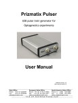
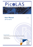
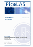
User Manual
Rev. 09.01 valid from June 2009
LDP-V-KIT
1
Elements of the LDP-V-KIT
The LDP-V KIT includes a 15 V / 2 A wall power supply and two SMC-BNC cables to connect a LDP-V or
LDP-AV pulser.
The SMC-BNC cables are used to connect the trigger input and current monitor output. The wall power
supply provides the supply voltage for the pulser.
Connectors of the KIT
Supply Voltage:
Connect the power supply for the KIT and the pulser to the two pin screw terminal. Pay attention to the
correct polarity!
High Voltage Input (optional):
Connect the external high voltage power supply for the pulser to the two pin screw terminal.
Pay attention to the correct polarity!
Disable the integrated HV Supply on the Pulser!
Security Advise:
Advise Do not touch any leads of the HV Input connector and the pulser connector as
they are connected to a high voltage of up to 125 V, even if no external high voltage is applied!
Mounting of the KIT
First connect the SMC-BNC cable to the trigger input and the trigger source. Connect the second SMCBNC cable to the current monitor and an oscilloscope. Then mount the LDP-V KIT is directly on top of the
pulser. The 10-pin female connector on the KIT must fit onto the connector of the pulser. The three
mounting holes on the KIT must fit on the corresponding screw terminals of the pulser.
Absolute Maximum Ratings
HV-Input 0 .. 125V*
Supply Voltage 0 .. 15 V*
*The connected pulser’s limits have to be obeyed. See pulser datasheet and user manual for exact
specification.
2