1
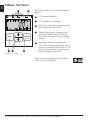
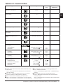
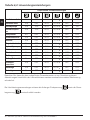
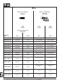
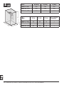
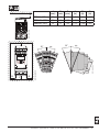
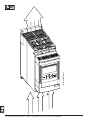
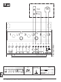
Softstarters Type PSE18...PSE370
User Manual short form
0-70
PSE
0-70
PSE
0
00-7
PSE
18-6
18-60
18-60
according to EN /IEC 60947-4-2
This manual belongs to:
___________________________________________________________
2 Softstarters Type PSE18...PSE370 User Manual short form 1SFC132059M9901
EN
1 Read me irst
Thank you for selecting this ABB PSE Softstarter. Read carefully and
be sure to understand all instructions before mounting, connecting and
coniguring the Softstarter.
This manual is a short form manual intended for quick and easy installation of the PSE Softstarter. For complete information, please see Softstarters Type PSE18...PSE370, Installation and Commissioning Manual
available on: http://www.abb.com/lowvoltage
In this User Manual, the following symbols are used:
The caution icon
located in the left margin, indicates the presence
of a hazard which could result in personal injury.
The warning icon
located in the left margin, indicates the presence of a hazard which could result in damage to equipment or property.
located in the left margin, alerts the reader to
The information sign
pertinent facts and conditions.
The graphics symbol
located in the right margin provides a
reference to graphical information.
Mounting and electrical connection of the softstarter shall be made in
accordance with existing laws and regulations and be performed by
authorized personnel.
When unpacking your new PSE Softstarter, please check for visible
damage. If any is found, contact your local sales agent.
Never lift the softstarter by the connection bars, since it may cause
damage to the product.
Service and repair should be performed by authorized personnel only.
Note that unauthorized repair may affect the warranty.
Data in this manual subject to change without notice.
4 Softstarters Type PSE18...PSE370 User Manual short form 1SFC132059M9901
EN
2 Description
The PSE Softstarter is microprocessor-based and designed with the
latest technology for soft starting, and when applicable, soft stopping of
standard squirrel cage motors.
The PSE Softstarter has several features as standard.
•
Integrated by-pass.
•
Torque control ramp during start and stop.
•
Built in Electronic Motor protection.
•
Kick start.
•
Analog out signal can vary in the range 4 - 20 mA, corresponding
to 0 - 120 percent of set Ie (terminals 13 and 14). 100 percent corresponds to 17.3 mA.
•
Three output signal relays to indicate Top of Ramp (TOR), trip
events (FAULT) and running (RUN).
The PSE Softstarter can be controlled in two ways:
•
Hardwire inputs using terminals 8 and 9, in circuit with terminals 11
or 12.
•
Fieldbus communication interface.
1.
Check that you have the correct product in regards to operational voltage, control supply voltage, rated motor data, and used numbers of
starts per hour.
01
The PSE18...PSE370 Softstarters operates over wide voltage ranges.
•
Rated operational voltage 208 - 600 V AC
•
Rated control supply voltage 100 - 250 V AC
The product should only be used within the speciied ratings. Be aware
of the ambient temperature and altitude above sea level. Derating is
required above 40 °C (104 °F) and above 1000 m (3281 ft). For more
details see Softstarters Type PSE18...PSE370, Installation and Commissioning Manual, Document ID 1SFC132057M0201 available on:
http://www.abb.com/lowvoltage.
2.
Make sure that any of the recommended short circuit protections are
used according to prevailing standards.
02
Softstarters Type PSE18...PSE370 User Manual short form 1SFC132059M9901 5
EN
3 Mounting
The PSE Softstarters exist in three different physical sizes which are
designed to be mounted with M6 bolts, or bolts of equivalent dimension
and strength.
1.
Identify the correct drawing with dimensions for your softstarter
2.
Verify the drilling plan.
3.
In applications where the softstarter is installed in an enclosure, make
sure that the enclosure size is not smaller than the minimum recommended. Select size from the applicable table for IEC or
.
4.
Check that the distance to wall and front, as well as the mounting
angle fulills the requirements.
5.
Ensure a free low of air through the product.
03
04
05
06
Risk of damage to property. Ensure that no liquids, dust or conductive
parts enter the softstarter.
Using a too small enclosure and/or failure to follow the instructions in
other ways, may result in overheating of the PSE Softstarter and operational disturbances.
6 Softstarters Type PSE18...PSE370 User Manual short form 1SFC132059M9901
07
EN
4 Connection
This product has been carefully manufactured and tested but there is a
risk that damage can occur from such as transportation and incorrect
handling. Therefore, the procedure below should be followed during
initial installation:
Hazardous voltage. Will cause death or serious injury. Turn off and lock
out all power supplying this device before starting work on this equipment.
Mounting and electrical connection of the softstarter shall be made in
accordance with existing laws and regulations and be performed by
authorized personnel.
Before connecting the Softstarters PSE size 18...170 to operational
supply voltage for the irst time, the control supply voltage must be
turned on to ensure that the by-pass relays are in the open position.
This is necessary to avoid unintentional starting of the equipment during
connection.
1.
Connect the terminals 1L1, 3L2 and 5L3 to the operational voltage on
the power supply line side.
2.
Connect the terminals 2T1, 4T2 and 6T3 to the motor.
08
08
Connecting Softstarters PSE18...PSE370 Inside Delta will cause damage to the equipment, and there is a risk of death or serious injury.
PSE
In Line
1SFC132263F0001
1SFC132265F0001
PSE
Inside Delta
Softstarters Type PSE18...PSE370 User Manual short form 1SFC132059M9901 7
EN
Capacitors for power factor compensation are not allowed between
the softstarter and the motor, since this can cause current peaks which
can damage the thyristors in the softstarter. If such capacitors are to be
used, they should be connected on the line side of the softstarter.
3.
Connect control supply voltage to terminals 1 and 2.
4.
Connect terminal 14 to the functional earth.
09
10
The earthing is not a protective earth, it is a functional earth. The
earthing cable should be as short as possible. Maximum length 0.5 m.
The earthing cable should be connected to the mounting plate, which
should also be earthed.
5.
Connect the start, stop and other control circuits including the analog
out to the terminals, 8, 9, 10, 11, 12, 13 and 14 if needed. This section
is using an internal 24 V DC. Do not feed with any external voltage.
11
Do not connect an external voltage to the control terminals 8, 9, 10, 11,
12, 13 and 14. Failure to observe the above may damage the softstarter and the warranty may no longer be valid.
6.
Connect terminals 3, 4, 5, 6 and 7 when using the signal output relays.
These are potential free contacts for maximum 250 V AC, 1,5 A AC-15.
Make sure you are using the same voltage level within this terminal
section.
The same external voltage (maximum 24 V DC or maximum 250 V AC)
must be connected to the output relay terminals 3, 4, 5, 6 and 7. Failure
to observe the above may damage the softstarter and the warranty may
no longer be valid.
8 Softstarters Type PSE18...PSE370 User Manual short form 1SFC132059M9901
12
Switch ON the control supply voltage, terminals 1 and 2.
8.
Continue to conigure parameters as described in chapter 6, Settings.
9.
Switch ON the operational voltage.
There is some lexibility in the connecting of your softstarter, but following the steps above will enable operation of the PSE softstarter. An
example of a complete installation can be found in the graphics section.
The irst one uses fuses and contactors and the second one uses a
circuit breaker.
EN
7.
13
Depending on the two phase control, a connected motor terminal
always carries live hazardous voltage. Do not touch terminals when
voltage is applied. Output terminals will have live voltage even when the
device is OFF. This can cause death or serious injury.
Softstarters Type PSE18...PSE370 User Manual short form 1SFC132059M9901 9
A
Ready
Run
Exit
Protection
Fault
A
LED status indicators.
B
LCD display with backlight.
C
Exit key for cancelling parameter edits
and exiting one menu level.
D
Select/Reset key for changing and
storing parameter values, entering
one menu level, and to reset tripping
events.
E
Navigation keys for navigating the
menu and changing parameter values.
Flashing numbers or text shown in the
display indicates that the menu/value
can be changed or scrolled.
Select
Reset
C
The HMI consists of the parts indicated in
igure 5.1.
B
E
D
1SFC132235F0001
EN
5 Basic functions
Figure 5.1: HMI
Refer to the timing diagram for the basic
functions of the softstarter.
10 Softstarters Type PSE18...PSE370 User Manual short form 1SFC132059M9901
14
EN
6 Softstarter settings
The PSE Softstarters can provide soft start and stop with two different
basic functions.
•
•
Voltage ramp
Torque control ramp
All PSE Softstarters need to be conigured to the rated current of the
motor. Since the motor must be connected In Line, set the rated current
to the value written on the rating plate of the motor. Use the following
procedure to change this parameter (Ie):
1.
From the Information level, enter the Settings level by pressing the
Select key. See graphics 15 A .
2.
Press select again to enable editing of the Ie parameter. This is indicated by a lashing value. See graphics 15 B .
15
When setting the current limit, and Initial/End Voltage, be aware that the
starting current must be high enough to enable for the motor to reach
the rated speed. The lowest possible current depends on the performance of the motor and the characteristics of the load.
3.
Increase or decrease the value by pressing the Up or Down keys repeatedly. Holding the key down will speed up the change. See graphics 15 C .
4.
When the rated current of the motor is reached, press the Select key
again to save. See graphics 15 D .
5.
If needed, continue to set other parameters according to the application following the same procedure.
15
Softstarters Type PSE18...PSE370 User Manual short form 1SFC132059M9901 11
EN
The motor may start unexpectedly if there is a start signal present,
when doing any of the actions listed below.
• Switching from one type of control to another (ieldbus control/
hardwire control).
• Resetting events.
• If using automatic event reset.
The PSE Softstarter has several parameters available that it various
types of applications. All available parameters and application settings
can be found in tables 6.1 and 6.2.
By pressing both navigation keys for a minimum of four seconds, all
parameter settings will be protected from unintentional change.
Repeating this for a period of two seconds will unlock the LCD display,
and allow changes to the parameter settings.
Read the Softstarters Type PSE18...PSE370, Installation and Commissioning Manual, Document ID 1SFC132057M0201 available on: http://
www.abb.com/lowvoltage.
12 Softstarters Type PSE18...PSE370 User Manual short form 1SFC132059M9901
16
Description
Display
Setting range
Default
value
Individual
Individual
Start Ramp time
1...30 s
10 s
Stop Ramp time
OFF, 1...30 s
OFF
Initial/End Voltage
30...70 %
40 %
Current Limit
1.5...7 x Ie
7.0 x Ie
Torque Control during start
ramp
OFF, On
OFF
Torque Control during stop
ramp
OFF, On
On
OFF, 30...100 %
OFF
OFF, 10A, 10, 20, 30
HAnd, Auto 1
10
HAnd
Underload Protection
Level
Type of Operation
OFF, 0.2...1 x Ie
HAnd, Auto 1
OFF
HAnd
Locked Rotor Protection
Level
Type of Operation
OFF, 0.5...7 x Ie
HAnd, Auto 1
OFF
HAnd
FieldBus Control
Fieldbus Address
Download Parameter
Operation When Fault
Type of Operation
OFF, On 2
0...255
dPon, dPoF 4
trIP, LocC 5
HAnd, Auto 6
OFF
255 3
Rated Current of motor
Kick Start
Electronic Motor Overload
Protection (EOL)
Tripping class
Type of operation
HAnd = Manual reset of the protection or fault.
Auto = Automatic reset of the protection or fault.
2 OFF = Fieldbus is not allowed to control the motor.
On = Fieldbus is allowed to control the motor.
3 255 = Address of the FieldBusPlug will be used.
4 dPon = Download of parameters from PLC enabled.
dPoF = Download of parameters from PLC blocked.
1
Actual
setting
dPon
LocC
HAnd
5 Accessible only if On is previously selected.
trIP = Trip on fault.
LocC = Local control on fault - hardwire control is possible
6 Accessible only if trIP is previously selected.
HAnd = Manual reset of the protection or fault.
Auto = Automatic reset of the protection or fault.
Softstarters Type PSE18...PSE370 User Manual short form 1SFC132059M9901 13
EN
Table 6.1: Parameter list
EN
Table 6.2: Application settings
Recommended basic setting
Centrifugal fan
10 s
OFF
40 %
5.0 x Ie
OFF
OFF
Axial fan
10 s
OFF
40 %
5.0 x Ie
OFF
OFF
Centrifugal
pump
10 s
10 s
40 %
5.0 x Ie
OFF
On
High pressure
pump
10 s
10 s
50 %
5.5 x Ie
OFF
On
Compressor
5s
OFF
40 %
4.5 x Ie
OFF
OFF
Grinder
10 s
OFF
40 %
5.0 x Ie
OFF
OFF
Mixer
10 s
OFF
40 %
5.0 x Ie
OFF
OFF
Bow thruster
10 s
OFF
40 %
4.5 x Ie
OFF
OFF
Hydraulic pump
10 s
OFF
40 %
4.5 x Ie
OFF
OFF
Crusher
10 s
OFF
40 %
5.0 x Ie
OFF
OFF
Conveyor belt
10 s
OFF
50 %
5.0 x Ie
OFF
OFF
Escalator
10 s
OFF
40 %
4.5 x Ie
OFF
OFF
Lift/Elevator
10 s
OFF
40 %
4.5 x Ie
OFF
OFF
Cutter
10 s
OFF
40 %
5.0 x Ie
OFF
OFF
Band saw
10 s
OFF
40 %
5.0 x Ie
OFF
OFF
Circular saw
10 s
OFF
40 %
5.0 x Ie
OFF
OFF
Please note that the parameter values above are to be used as a guide only. Variations in load
conditions may require additional tuning.
For Heavy Duty applications the Initial/End Voltage
might need to be increased.
as well as the Current Limit
14 Softstarters Type PSE18...PSE370 User Manual short form 1SFC132059M9901
Depending on PSE Softstarter coniguration, different events may be
signalled on the LCD. All event codes are found in table 7.1: Event list.
Table 7.1: Event list
Event
code
Event
Cause
SF20
Software fault
Fault in software
SF3x
1
Shunt fault
By-pass relay does not open or thyristor short
circuit
SF4x
1
By-pass open
By-pass relay or by-pass contactor does not
close
Softstarter thermal overload
Thyristors overheated
Phase loss fault
Power loss on operational current on one or
several phases
SF50
EF1x
1
EF20
Bad network quality
Excessive disturbances in the operational supply network
Current lost fault
Operational current on one or several phases
lost
EF40
Fieldbus fault
Fault on Fieldbus communication
EF50
Low supply voltage
Voltage too low or briely interrupted in supplying network for softstarter
High current fault
Operational current higher than 8 x Ie
P1
Motor overload protection
Load on motor higher than motor rating and
corresponding selected EOL Class.
Current limit parameter is set on a too low
value.
P2
Underload protection
Load on motor too low
P3
Locked rotor protection
Load on motor too high for a short time
EF3x
EF6x
1
1
SF = Softstarter fault
EF = External fault
P = Protection
1
x = phase number, 4 indicates multiple or unknown phase
Softstarters Type PSE18...PSE370 User Manual short form 1SFC132059M9901 15
EN
7 Troubleshooting
1 Bitte zuerst lesen
DE
Vielen Dank, dass Sie sich für diesen PSE-Sanftanlasser von ABB entschieden haben. Lesen Sie vor Montage, Anschluss und Koniguration
des Softstarters alle Anweisungen genau durch.
Dieses Handbuch ist eine Kurzanleitung zur schnellen und einfachen
Installation des PSE-Softstarters. Ausführliche Informationen siehe
„Sanftanlasser Type PSE18...PSE370, Handbuch für Installation und
Inbetriebnahme“, abrufbar auf: http://www.abb.com/lowvoltage
In diesem Benutzerhandbuch werden folgende Symbole verwendet:
Das Symbol Achtung
gefahr hin.
am linken Rand weist auf eine Verletzungs-
Das Symbol Warnung
am linken Rand weist auf die Gefahr von
Sachschäden bzw. der Beschädigung der Ausrüstung hin.
am linken Rand weist den Leser auf
Das Symbol Information
nützliche Informationen und Bedingungen hin.
Das Symbol Graiken
Informationen hin.
am linken Rand weist auf graische
Montage und Anschluss des Softstarters an das Stromnetz müssen
unter Einhaltung bestehender Gesetze und Vorschriften erfolgen und
dürfen nur von autorisiertem Fachpersonal ausgeführt werden.
Achten Sie beim Auspacken Ihres neuen PSE-Softstarters auf sichtbare
Schäden. Sofern vorhanden, wenden Sie sich an Ihren Händler vor Ort.
Heben Sie den Softstarter niemals an den Anschlussschienen hoch, da
dies das Produkt beschädigen kann.
Der Softstarter darf nur von autorisiertem Personal gewartet und repariert werden. Beachten Sie, dass die Garantie verfallen kann, wenn eine
Reparatur durch nicht autorisiertes Personal ausgeführt wird.
Angaben in diesem Handbuch können sich ohne vorherige Ankündigung ändern.
28 Softstarter Typ PSE18...PSE370 Kurzbetriebsanleitung 1SFC132059M9901
2 Beschreibung
Der PST-Softstarter basiert auf einem Mikroprozessor und nutzt die
neueste Technologie für sanfte Starts (und ggf. Stops) von Käigläufermotoren.
DE
Der PSE-Softstarter besitzt eine Reihe von Standardfunktionen.
•
Integrierter Bypass
•
Drehmomentregelung bei Start und Stopp.
•
Integrierter elektronischer Motorschutz
•
Kickstart
•
Analoges Ausgangssignal im Bereich 4 bis 20 mA, entsprechend 0
bis 120 Prozent von Ie (Klemmen 13 und 14). 100 Prozent entsprechen 17,3 mA.
•
Drei Ausgangssignalrelais zur Anzeige von TOR (Top of Ramp),
Auslöseereignis (FAULT) und Betrieb (RUN).
Der PSE-Softstarter kann auf zwei Arten gesteuert werden:
•
Kabelsteuerung über die Klemmen 8 und 9 bzw. eingeschleift über
die Klemmen 11 oder 12.
•
Feldbus-Kommunikationsschnittstelle
1.
Stellen Sie sicher, dass Sie in Bezug auf Betriebsspannung, Steuerspannungsversorgung, Motornenndaten und Anzahl von Motorstarts
pro Stunde das richtige Produkt verwenden.
01
Die Softstarter PSE18...PSE370 haben einen großen Spannungsbereich.
•
Nennbetriebsspannung 208 - 600 V AC
•
Nennsteuersspannungsversorgung 100 - 250 V AC
Dieses Produkt sollte nur innerhalb der angegebenen Nennwerte verwendet werden. Achten Sie auf die Umgebungstemperatur und Höhe
über Normalnull. Oberhalb von 40 °C (104 °F) und über 1000 m (3281
ft) ist eine entsprechende Lastminderung anzusetzen. Weitere Informationen siehe „Sanftanlasser Type PSE18...PSE370, Handbuch für
Installation und Inbetriebnahme“, Dokumenten-ID 1SFC132057M0101,
abrufbar auf: http://www.abb.com/lowvoltage.
2.
Stellen Sie sicher, dass eine der empfohlenen Kurzschlusssicherungen
entsprechend den lokalen Vorschriften angewendet werden.
02
Softstarter Typ PSE18...PSE370 Kurzbetriebsanleitung 1SFC132059M9901 29
3 Montage
Die PSE-Softstarter sind in drei verschiedenen Größen erhältlich und
werden mit M6-Schrauben oder Schrauben mit ähnlichen Abmessungen und Stärken montiert.
Ermitteln Sie die richtige Zeichnung mit den Abmessungen Ihres Softstarters.
2.
Vergleichen Sie mit der Bohrzeichnung.
3.
Wenn der Softstarter in einem Gehäuse installiert wird, stellen Sie
sicher, dass das Gehäuse die empfohlenen Mindestmaße nicht unterschreitet. Wählen Sie die Größe aus der entsprechenden IEC-Tabelle
oder
.
4.
Stellen Sie sicher, dass der Abstand zur Wand und Vorderseite und der
Anbauwinkel den Anforderungen entspricht.
5.
Stellen Sie sicher, dass das Produkt gut belüftet ist.
DE
1.
03
04
05
06
Gefahr von Beschädigungen: Stellen Sie sicher, dass keine Flüssigkeiten, Staub oder leitende Teile in den Softstarter gelangen.
Ein zu kleines Gehäuse und/oder anderweitige Nichtbeachtung der Installationsanweisungen kann zu einer Überhitzung des PSE-Softstarters
und zu Betriebsstörungen führen.
30 Softstarter Typ PSE18...PSE370 Kurzbetriebsanleitung 1SFC132059M9901
07
4 Anschluss
DE
Dieses Product wurde sorgfältig hergestellt und geprüft, es besteht aber
die Gefahr, dass Beschädigungen durch Transport oder unsachgemäße
Behandlung aufgetreten sind. Daher sollte bei der ersten Installation das
Verfahren unten durchgeführt werden:
Gefährliche Spannung. Führt zu schweren Verletzungen oder zum Tod.
Schalten Sie vor der Arbeit an diesem Gerät dessen gesamte Energieversorgung sicher aus.
Montage und Anschluss des Softstarters an das Stromnetz müssen
unter Einhaltung bestehender Gesetze und Vorschriften erfolgen und
dürfen nur von autorisiertem Fachpersonal ausgeführt werden.
Vor dem erstmaligen Anschließen des Softstarters PSE 18...170 an die
Betriebsspannungsversorgung, muss die Steuerspannungsversorgung
eingeschaltet sein, damit die Bypass-Relais geöffnet sind. Dies ist erforderlich, um ein unbeabsichtigtes Starten der Ausrüstung während des
Anschließens zu verhindern.
1.
Verbinden Sie die Klemmen 1L1, 3L2 und 5L3 mit der Betriebsspannung der Stromversorgungsleitung.
2.
Verbinden Sie die Klemmen 2T1, 4T2 und 6T3 mit dem Motor.
08
08
Das Anschließen des Softstarters PSE18...PSE370 in Wurzel-3-Schaltung beschädigt die Ausrüstung und kann zu schweren Verletzungen
oder zum Tod führen.
PSE
In Reihe
1SFC132263F0001
1SFC132265F0001
PSE
Wurzel-3-Schaltung
Softstarter Typ PSE18...PSE370 Kurzbetriebsanleitung 1SFC132059M9901 31
DE
Das Anschließen von Kondensatoren zur Kompensation des Leistungsfaktors zwischen Softstarter und Motor ist nicht erlaubt, da dies zu
Stromspitzen und damit zum Durchbrennen der Thyristoren im Softstarter führen kann. Wenn solche Kondensatoren verwendet werden,
müssen Sie an der Netzseite des Softstarters angeschlossen werden.
3.
Schließen Sie die Steuerspannungsversorgung an Klemme 1 und 2 an.
09
4.
Schließen Sie Klemme 14 an Funktionserde an.
10
Die Erdung ist keine Schutzerdung sondern eine Funktionserdung. Das
Erdungskabel sollte so kurz wie möglich sein. Die Maximallänge beträgt
0,5 m. Das Erdungskabel sollte mit der Montageplatte verbunden werden. Diese sollte ebenfalls geerdet werden.
5.
Verbinden Sie Start-, Stopp und andere Steuerkreise, einschließlich
der analogen Ausgänge, nach Bedarf mit den Klemmen 8, 9, 10, 11,
12, 13 und 14. Dieser Abschnitt verwendet eine interne 24-V-DC-Spannungsquelle. Legen Sie keine externe Spannung an.
11
Legen Sie an die Klemmen 8, 9, 10, 11, 12, 13 und 14 keine externe
Spannung an. Die Nichtbeachtung des oben Genannten kann zur Beschädigung des Softstarters und zum Erlöschen der Garantie führen.
6.
Schließen Sie bei Verwendung der Signalausgangsrelais die Klemmen
3, 4, 5, 6 und 7 an. Dabei handelt es sich um potentialfreie Anschlüsse
für maximal 250 V AC, 1,5 A AC-15. Stellen Sie sicher, dass Sie in diesem Anschlussbereich denselben Spannungspegel verwenden.
An die Ausgangsrelaisklemmen 3, 4, 5, 6 und 7 muss dieselbe externe
Spannung (max. 24 V DC oder max. 250 V AC) angelegt werden. Die
Nichtbeachtung des oben Genannten kann zur Beschädigung des
Softstarters und zum Erlöschen der Garantie führen.
32 Softstarter Typ PSE18...PSE370 Kurzbetriebsanleitung 1SFC132059M9901
12
Schalten Sie die Steuerspannungsversorgung (Klemme 1 und 2) an.
8.
Fahren Sie mit der Koniguration der Parameter, wie in Kapitel 6 „Einstellungen“ beschrieben, fort.
9.
Schalten Sie die Betriebsspannung ein.
Der Anschluss des Softstarters kann zwar auch etwas abweichen,
mit der Einhaltung der oben genannten Schritte ist der Betrieb des
PSE-Softstarters jedoch gewährleistet. Ein Beispiel einer vollständigen
Installation inden Sie im Abschnitt „Graiken“. Bei der Ersten werden
Sicherungen und Schaltschütze, bei der Zweiten ein Leistungsschalter
verwendet.
13
Je nach der Zwei-Phasen-Steuerung, führt eine angeschlossene Motorklemme stets lebensgefährliche Spannung. Berühren Sie niemals die
Klemmen nach Einschalten der Spannung. Ausgangsklemmen führen
auch bei ausgeschaltetem Gerät lebensgefährliche Spannung. Dies
kann zu schweren Verletzungen oder zum Tod führen.
Softstarter Typ PSE18...PSE370 Kurzbetriebsanleitung 1SFC132059M9901 33
DE
7.
5 Grundfunktionen
A
Run
Protection
Fault
DE
Ready
Das Display besteht aus den in Abbildung
5.1 dargestellten Teilen.
B
Exit
LED-Statusanzeigen
B
LCD-Anzeige mit Beleuchtung
C
Exit-Taste zum Abbrechen von Parametereingaben und zum Verlassen
einer Menüebene.
D
Select/Reset-Taste zum Ändern
und Speichern von Parametern, zur
Auswahl einer Menüebene, und zum
Zurücksetzen von Auslöseereignissen.
E
Navigationstasten zum Blättern durch
die Menüs und Ändern von Parameterwerten. Blinkende Zahlen oder blinkender Text im Display bedeuten, dass das
Menü/der Wert geändert oder gescrollt
werden kann.
E
D
Abbildung 5.1: Display
1SFC132235F0001
Select
Reset
C
A
Siehe Steuerungsdiagramm für die Grundfunktionen des Softstarters.
34 Softstarter Typ PSE18...PSE370 Kurzbetriebsanleitung 1SFC132059M9901
14
6 Einstellungen des Softstarters
Der PSE-Softstarter kann sanfte Starts und sanfte Stopps mit zwei
verschiedenen Grundfunktionen steuern.
Spannungsregelung
Drehmomentregelung
DE
•
•
Alle PSE-Softstarter müssen auf den Nennstrom des Motors eingenstellt werden. Da der Motor in Reihe angeschlossen werden muss,
setzen Sie den Nennstrom auf den auf dem Motor angegebenen Wert.
Gehen Sie wie folgt vor, um diesen Parameter (Ie) zu ändern:
1.
Wechseln Sie von der Statusebene zur Einstellungsebene, indem Sie
die Taste Select drücken. Siehe Graik 15 A .
2.
Drücken Sie erneut Select, um die Bearbeitung des Parameters Ie zu
aktivieren. Dies wird durch das Blinken des Werts angezeigt. Siehe
Graik 15 B .
15
Achten Sie beim Einstellen der Strombegrenzung und der Anfangs-/
Endspannung darauf, dass der Startstrom groß genug zum Erreichen
der Nenndrehzahl des Motors sein muss. Der niedrigste mögliche
Strom hängt von der Motorleistung und den Lasteigenschaften ab.
3.
Erhöhen bzw. verringern Sie den Wert durch wiederholtes Drücken
der Taste Up bzw. Down. Durch Gedrückthalten der Taste kann das
Ändern des Werts beschleunigt werden. Siehe Graik 15 C .
4.
Drücken Sie nach Erreichen des Nennstroms des Motors die Taste
Select erneut, um den Wert zu speichern. Siehe Graik 15 D .
5.
Gehen Sie je nach Anwendungsfall zum Ändern von anderen Parametern analog vor.
15
Softstarter Typ PSE18...PSE370 Kurzbetriebsanleitung 1SFC132059M9901 35
DE
Der Motor kann unerwartet starten, wenn während einer der folgenden
Aktionen ein Startsignal vorhanden ist.
• Wechsel von einem Steuerungstyp zu einem anderen (Feldbussteuerung/Kabelsteuerung)
• Zurücksetzen von Ereignissen
• Bei Verwendung des automatischen Zurücksetzens von Ereignissen
Der PSE-Softstarter kann über eine Vielzahl von Parametern für verschiedene Anwendungsarten koniguriert werden. In den Tabellen 6.1
und 6.2 sind alle verfügbaren Parameter und Anwendungseinstellungen
aufgeführt.
Durch gleichzeitiges Gedrückthalten beider Navigationstasten für
mindestens vier Sekunden werden alle Parametereinstellungen vor
unbeabsichtigtem Ändern geschützt.
Durch nochmaliges Gedrückthalten beider Navigationstasten für zwei
Sekunden wird die LCD-Anzeige wieder entsperrt und für Parameteränderungen freigegeben.
Weitere Informationen siehe „Sanftanlasser Type PSE18...PSE370,
Handbuch für Installation und Inbetriebnahme“, Dokumenten-ID 1SFC132057M0101, abrufbar auf: http://www.abb.com/lowvoltage.
36 Softstarter Typ PSE18...PSE370 Kurzbetriebsanleitung 1SFC132059M9901
16
Tabelle 6.1: Parameterliste
Anzeige
Einstellungsbereich
Standardwert
Nennstrom des Motors
Einzeln
Einzeln
Startregelzeit
1...30 s
10 s
Stoppregelzeit
OFF (Aus), 1...30 s
OFF
Anfangs-/Endspannung
30...70 %
40 %
Strombegrenzung
1,5...7 x Ie
7,0 x Ie
Drehmomentregelung bei Start
und Stopp
OFF (Aus), On (Ein)
OFF
Drehmomentregelung bei
Stopp
OFF (Aus), On (Ein)
On
Kickstart
OFF (Aus), 30…100 %
OFF
Elektronischer Motorüberlastschutz (EOL)
Abschaltklasse
Betriebsart
OFF (Aus), 10A, 10, 20, 30
HAnd, Auto 1
10
HAnd
Unterlastschutz
Schwelle
Betriebsart
OFF (Aus), 0,2..0,1 x Ie
HAnd, Auto 1
OFF
HAnd
Rotorblockadeschutz
Schwelle
Betriebsart
OFF (Aus), 0,5...7 x Ie
HAnd, Auto 1
OFF
HAnd
Feldbussteuerung
Feldbusadresse
Parameter herunterladen
Betrieb bei Fehler
Betriebsart
OFF (Aus), On (Ein) 2
0...255
dPon, dPoF 4
trIP, LocC 5
HAnd, Auto 6
OFF
255 3
dPon
LocC
HAnd
Aktuelle
Einstellung
5 Nur verfügbar, wenn zuvor On (Ein) gewählt wurde.
HAnd = Manuelles Zurücksetzen der Schutzfunktion oder
des Fehlers.
trIP = Auslösen bei Fehler.
Auto = Automatisches Zurücksetzen der Schutzfunktion
LocC = Lokale Steuerung bei Fehler - Kabelsteuerung
oder des Fehlers.
möglich
2 OFF (Aus) = Feldbus für Motorsteuerung nicht aktiviert.
6 Nur verfügbar, wenn zuvor trIP gewählt wurde.
On (Ein)= Feldbus für Motorsteuerung aktiviert.
HAnd = Manuelles Zurücksetzen der Schutzfunktion
3 255 = Adresse des FieldBusPlug wird verwendet.
oder des Fehlers.
4 dPon = Herunterladen von Parametern vom PLC aktiviert
Auto = Automatisches Zurücksetzen der Schutzfunktion
dPoF = Herunterladen von Parametern vom PLC deaktiviert
oder des Fehlers.
1
Softstarter Typ PSE18...PSE370 Kurzbetriebsanleitung 1SFC132059M9901 37
DE
Beschreibung
Tabelle 6,2: Anwendungseinstellungen
DE
Empfohlene Grundeinstellungen
Ventilator radial
10 s
OFF
40 %
5,0 x Ie
OFF
OFF
Ventilator axial
10 s
OFF
40 %
5,0 x Ie
OFF
OFF
Kreiselpumpe
10 s
10 s
40 %
5,0 x Ie
OFF
On
Hochdruckpumpe
10 s
10 s
50 %
5,5 x Ie
OFF
On
Kompressor
5s
OFF
40 %
4,5 x Ie
OFF
OFF
Schleifmaschine
10 s
OFF
40 %
5,0 x Ie
OFF
OFF
Mischer
10 s
OFF
40 %
5,0 x Ie
OFF
OFF
Bugstrahlantrieb
10 s
OFF
40 %
4,5 x Ie
OFF
OFF
Hydraulikpumpe
10 s
OFF
40 %
4,5 x Ie
OFF
OFF
Mahlwerk
10 s
OFF
40 %
5,0 x Ie
OFF
OFF
Förderband
10 s
OFF
50 %
5,0 x Ie
OFF
OFF
Rolltreppe
10 s
OFF
40 %
4,5 x Ie
OFF
OFF
Aufzug/Fahrstuhl
10 s
OFF
40 %
4,5 x Ie
OFF
OFF
Schneidemaschine
10 s
OFF
40 %
5,0 x Ie
OFF
OFF
Bandsäge
10 s
OFF
40 %
5,0 x Ie
OFF
OFF
Kreissäge
10 s
OFF
40 %
5,0 x Ie
OFF
OFF
Beachten Sie, dass die oben aufgeführten Parameterwerte nur zur Orientierung dienen.
Abweichungen hinsichtlich der Lastverhältnisse machen eventuell eine weitere Abstimmung
erforderlich.
Bei Hochleistungsanwendungen müssen die Anfangs-/Endspannung
begrenzung
eventuell erhöht werden.
38 Softstarter Typ PSE18...PSE370 Kurzbetriebsanleitung 1SFC132059M9901
sowie die Strom-
7 Fehlersuche
Je nach Koniguration des PSE-Softstarters können verschiedene Ereignisse auf dem LCD signalisiert werden. Tabelle 7.1 enthält alle Ereigniscodes:
Ereignisliste
DE
Tabelle 7.1: Ereignisliste
Ereignis- Ereignis
code
Grund
SF20
Softwarefehler
Fehler in der Software
SF3x
1
Shunt-Fehler
Bypass-Relais öffnet nicht oder Thyristor kurzgeschlossen
SF4x
1
Bypass geöffnet
Bypass-Relais oder Bypass-Schütz schließt
nicht
SF50
Softstarter thermisch überlastet
Thyristoren überhitzt
Phasenverlust
Leistungsverlust des Betriebsstroms auf einer
oder mehreren Phasen
Schlechte Netzqualität
Beträchtliche Störungen in der Netzversorgung
Strom verloren
Betriebsstrom auf einer oder mehreren Phasen
verloren
EF40
Feldbusfehler
Fehler in der Feldbuskommunikation
EF50
Steuerspannungsversorgung
zu niedrig
Spannung im Versorgungsnetz des Softstarters
zu niedrig oder kurzzeitig unterbrochen
Hochstrom
Betriebsstrom höher als 8 x Ie
P1
Elektronischer Motorüberlastschutz
Motorlast höher als die Motornennleistung und
die entsprechend ausgewählte EOL-Klasse.
Der aktuelle Grenzparameter ist auf einen zu
geringen Wert eingestellt
P2
Unterlastschutz
Motorlast zu gering
P3
Rotorblockadeschutz
Motorlast kurzzeitig zu hoch
EF1x
1
EF20
EF3x
EF6x
1
1
SF = Softstarter-Fehler
EF = Externer Fehler
P = Schutz
1
x = Phasennummer, 4 zeigt Mehrfach- oder unbekannte Phase an
Softstarter Typ PSE18...PSE370 Kurzbetriebsanleitung 1SFC132059M9901 39
01
t ≤ + 40 oC (104 oF)
IEC
220240 V
380400 V
500 V
208 V
220240 V
440480 V
550600 V
P (HP)
P (HP)
P (HP)
P (HP)
Softstarter
type
Ie (A)
P (kW)
P (kW)
P (kW)
FLA (A)
PSE18
18
4
7.5
11
18
5
5
10
15
PSE25
25
5.5
11
15
25
7.5
7.5
15
20
PSE30
30
7.5
15
18.5
28
7.5
10
20
25
PSE37
37
9
18.5
22
34
10
10
25
30
PSE45
45
11
22
30
42
10
15
30
40
PSE60
60
15
30
37
60
20
20
40
50
PSE72
72
18.5
37
45
68
20
25
50
60
PSE85
85
22
45
55
80
25
30
60
75
PSE105
106
30
55
75
104
30
40
75
100
PSE142
143
40
75
90
130
40
50
100
125
PSE170
171
45
90
110
169
60
60
125
150
PSE210
210
59
110
132
192
60
75
150
200
PSE250
250
75
132
180
248
75
100
200
250
PSE300
300
90
160
200
302
100
100
250
300
PSE370
370
110
200
250
361
125
150
300
350
PSE18 - 600 - 70
Control supply voltage: 70 = 100 - 250 V AC
Operational voltage: 600 V
Current rating: 18 A
Softstarter range
Softstarters Type PSE18...PSE370 User Manual short form 1SFC132059M9901 173
02
IEC
Type 2 co-ordination
Type 1 co-ordination
Fuses
MCCB
MCCB
600V
Iq 85kA
400V
Iq 35kA
400V
Iq 50kA
Semicond. Bussmann
DIN 43620
Softstarter
Type
Type
Rating
Type
Type
PSE18-600-70
170M1563
40A
T2N160 MA20
T2S160 MA20
PSE25-600-70
170M1564
50A
T2N160 MA32
T2S160 MA32
PSE30-600-70
170M1566
80A
T2N160 MA52
T2S160 MA52
PSE37-600-70
170M1567
100A
T2N160 MA52
T2S160 MA52
PSE45-600-70
170M1568
125A
T2N160 MA52
T2S160 MA52
PSE60-600-70
170M1569
160A
T2N160 MA80
T2S160 MA80
PSE72-600-70
170M1571
250A
T2L160 MA80
T2S160 MA80
PSE85-600-70
170M1572
315A
T2L160 MA100
T2S160 MA100
PSE105-600-70
170M3819
400A
T3N250 MA160
T3S250 MA160
PSE142-600-70
170M5809
450A
T3N250 MA200
T3S250 MA200
PSE170-600-70
170M5810
500A
T3N250 MA200
T3S250 MA200
PSE210-600-70
170M5812
630A
T4N320 PR221-I
In320
T4S320 PR221-I
In320
PSE250-600-70
170M5813
700A
T5N400 PR221-I
In400
T5S400 PR221-I
In400
PSE300-600-70
170M6812
800A
T5N400 PR221-I
In400
T5S400 PR221-I
In400
PSE370-600-70
170M6813
900A
T5N630 PR221-I
In630
T5S630 PR221-I
In630
174 Softstarters Type PSE18...PSE370 User Manual short form 1SFC132059M9901
Fuses
MCCB
MCCB
Normal breaker
550-600V
440-480V 550-600V
Standard breaker
440-480V
550-600V
High Fault
Current
85kA
Class J
Fuses
High
Fault
Current
High
Fault
Current
Normal
breaker
High
Fault
Current
High
Fault
Current
Standard
breaker
PSE18-600-70
40A
25kA
14kA
Ts3N070TW
35kA
25kA
Ts3L070TW
PSE25-600-70
50A
Ts3N100TW
Ts3L100TW
PSE30-600-70
60A
Ts3N100TW
Ts3L100TW
PSE37-600-70
80A
Ts3N125TW
Ts3L125TW
PSE45-600-70
100A
Ts3N150TW
Ts3L150TW
PSE60-600-70
125A
Ts3N150TW
Ts3L150TW
PSE72-600-70
150A
T4N250TW
T4S250TW
PSE85-600-70
175A
T5N300TW
T5S300TW
PSE105-600-70
225A
T5N300TW
T5S300BW
PSE142-600-70
300A
T5N400BW
T5S400BW
PSE170-600-70
350A
T5N400BW
T5S400BW
PSE210-600-70
450A
PSE250-600-70
500A
T6N600BW
T6S800BW
PSE300-600-70
600A
T6N800BW
T6S800BW
PSE370-600-70
600A
T6N800BW
T6S800BW
Softstarter
Type
18kA
35kA
20kA
T6N600BW
50kA
T6S600BW
Softstarters Type PSE18...PSE370 User Manual short form 1SFC132059M9901 175
6 mm (0.236 in)
03
PSE18...PSE105
6,5 mm (0.256 in)
6,5 mm (0.256 in)
185,5 mm (7.303 in)
3 mm (0.118 in)
90 mm (3.543 in)
80 mm (3.150 in)
PSE142...PSE170
7 mm (0.276 in)
13 mm (0.512 in)
30 mm (1.181 in)
37 mm (1.457 in)
3 mm (0.118 in)
90 mm (3.543 in)
245 mm (9.645 in)
230 mm (9.055 in)
PSE 18-600-70
1SFC132260F0001
5 mm (0.197 in)
109,5 mm (4.311 in)
3 mm (0.118 in)
35 mm (1.378 in)
113,5 mm (4.468 in)
219,5 mm (8.642 in)
295 mm (11.614 in)
221 mm (8.701 in)
278 mm (10.947 in)
PSE142-600-70
17,5 mm (0.689 in)
130 mm (5.118 in)
176 Softstarters Type PSE18...PSE370 User Manual short form 1SFC132059M9901
6,5 mm (0.256 in)
40 mm (1.575 in)
9,2 mm (0.363 in)
PSE210...PSE370
190 mm (7.480 in)
236,5 mm (9.311 in)
5 mm (0.197 in)
163,5 mm (6.437 in)
19,6 mm
(0.772 in)
125,5 mm (4.941 in)
43,75 mm
(1.723 in)
1SFC132266F0001
470 mm (18.503 in)
532 mm (20.944 in)
550 mm (21.653 in)
PSE210-600-70
Softstarters Type PSE18...PSE370 User Manual short form 1SFC132059M9901 177
04
mm
80 0 in)
5
1
.
(3
PSE18...PSE105
M6
(1/4
in)
n)
55 i
1SFC132271F0001
230
(9.0
mm
PSE142...PSE170
mm
113,5 in)
8
6
4
.
(4
)
1/4 in
M6 (
5 in)
10.94
m(
278 m
00-70
142-6
1SFC132272F0001
PSE
178 Softstarters Type PSE18...PSE370 User Manual short form 1SFC132059M9901
PSE210...PSE370
mm
163,5 in)
7
(6.43
)
1/4 in
M6 (
00-70
PSE
210-6
)
44 in
1SFC132273F0001
532
20.9
mm (
Softstarters Type PSE18...PSE370 User Manual short form 1SFC132059M9901 179
IEC
05
W (mm)
H (mm)
D (mm)
PSE18...105
400
500
260
PSE142...170
400
600
260
PSE210...370
600
1000
300
W (in)
H (in)
D (in)
min number
of latches
PSE18...105
20
24
12
1
PSE142...170
30
36
12
2
PSE210...370
36
48
16
1
D
W
1SFC132269F0001
H
180 Softstarters Type PSE18...PSE370 User Manual short form 1SFC132059M9901
06
A
(mm)
B
(mm)
C
(mm)
PSE18...105
20
10
100
0.787 0.394 3.937
PSE142...170
20
10
100
0.787 0.394 3.937
PSE210...370
20
10
100
0.787 0.394 3.937
A
(in)
B
(in)
C
(in)
1SFC132243F000
A
C
O
30
30 O
O
30
30 O
PSE 18-600-70
-70
PSE
PSE 18-600-70
18-600
PSE
18-600
B
C
B
1SFC132280F0001
1SFC132242F0001
-70
Softstarters Type PSE18...PSE370 User Manual short form 1SFC132059M9901 181
1SFC132240F0001
07
182 Softstarters Type PSE18...PSE370 User Manual short form 1SFC132059M9901
08
3L2
5L3
1SFC132241F0001
1L1
2T1 4T2 6T3
1L1
3L2
Using connection module
5L3
2T1
Using connection bars
AWG12 .. 6
6 Nm - 53 lb.in
M8
Cu 75°C only
2,5 .. 10 mm2
2x2,5 .. 2x10 mm2
AWG6 .. 2/0
4T2 6T3
8 Nm - 71 lb.in
Cu 75°C only
9 Nm - 80 lb.in
10 .. 70 mm2
2x10 .. 2x70 mm2
PSE142...170
1L1
2T1
3L2
5L3
4T2 6T3
11/6-16 UNF-2A
Using connection bars
Using connection module
ATK185: AWG4 to 300kcmil
Al Cu 75°C only
275 lb.in
2T1
3L2
5L3
4T2 6T3
18 Nm - 160 lb.in
3/4-16 UNF-2A
375 lb.in
max
24 mm
(0.945 in)
M8
PSE210...370
1L1
max
22 mm
(0.866 in)
M6
Using connection bars
Using connection module
ATK300: AWG4 to 400kcmil
ATK300/2: AWG4 to 500kcmil or
2xAWG4 to 2x500kcmil
Al Cu 75°C only
M10
28 Nm - 240 lb.in
max
30 mm
(1.181 in)
max
20 mm
(0.787 in)
max
5 mm
(0.197 in)
max
22 mm
(0.866 in)
max
8 mm
(0.315 in)
max
30 mm
(1.181 in)
max
10 mm
(0.394 in)
1SFC13275F0001
PSE18...105
Softstarters Type PSE18...PSE370 User Manual short form 1SFC132059M9901 183
09
N
1SFC132251F0001
L
2
3
4
5
6
7
8 9 10 11 12 13 14
M3
4 x 0,8 mm
(0.157 x 0.031 in)
0,5 Nm - 4,3 lb.in
184 Softstarters Type PSE18...PSE370 User Manual short form 1SFC132059M9901
AWG 24 ... 10
0,2 .. 4 mm2
2x0,2 .. 1,5 mm2
0,2 .. 4 mm2
2x0,2 .. 1,5 mm2
1SFC132281F0001
1
10
1
2
10
11
3
12
13
4
14
5
6
7
8 9 10 11 12 13 14
M3
0,5 Nm - 4,3 lb.in
3,5 x 0,6 mm
(0.138 x 0.24 in)
AWG 24 ... 12
0,2 .. 2,5 mm2
2x0,2 .. 1,5 mm2
0,2 .. 2,5 mm2
2x0,2 .. 1,5 mm2
1SFC132283F0001
9
Softstarters Type PSE18...PSE370 User Manual short form 1SFC132059M9901 185
11
Start
2
3
4
5
6
7
8
9 10 11 12 13 14
PSE 18-600-70
1
2
3
4
5
6
7
8 9 10 11 12 13 14
M3
3,5 x 0,6 mm
(0.138 x 0.024 in)
0,5 Nm - 4,3 lb.in
186 Softstarters Type PSE18...PSE370 User Manual short form 1SFC132059M9901
AWG 12 ... 24
0,2 .. 2,5 mm2
2x0,2 .. 1,5 mm2
0,2 .. 2,5 mm2
2x0,2 .. 1,5 mm2
1SFC132282F0001
1
1SFC132278F0001
Stop
Reset
1
2
3
4
5
6
7
8
9 10 11 12 13 14
1
2
3
4
5
6
7
8 9 10 11 12 13 14
M3
0,5 Nm - 4,3 lb.in
3,5 x 0,6 mm
(0.138 x 0.024 in)
AWG 24 ... 12
0,2 .. 2,5 mm2
2x0,2 .. 1,5 mm2
0,2 .. 2,5 mm2
2x0,2 .. 1,5 mm2
1SFC132282F0001
PSE 18-600-70
Softstarters Type PSE18...PSE370 User Manual short form 1SFC132059M9901 187
12
2
3
4
5
6
7
8
9 10 11 12 13 14
PSE 18-600-70
1
2
3
4
5
6
7
8 9 10 11 12 13 14
M3
4 x 0,8 mm
(0.157 x 0.031 in)
0,5 Nm - 4,3 lb.in
188 Softstarters Type PSE18...PSE370 User Manual short form 1SFC132059M9901
AWG 10 ... 24
0,2 .. 4 mm2
2x0,2 .. 1,5 mm2
0,2 .. 4 mm2
2x0,2 .. 1,5 mm2
1SFC132284F0001
1
1SFC132279F0001
AC
L1
L2
L3
N
13
L N
Start
Stop
8
9
11
Start
Stop
KM1
1L1 3L2 5L3
1 2
8
9
10
Run TOR
2T1 4T2 6T3
V
4
12
13 14
12
13 14
Fault
5
NC
NO
6
7
W
1SFC132237F0001
U
3
11
M
3
Circuit diagram PSE18...PSE370 (Fuse and contactor version)
L1
L2
L3
N
L N
MCCB
Start
Stop
8
9
11
Start
Stop
1 2
8
9
10
Run TOR
2T1 4T2 6T3
U
V
W
M
3
3
4
5
11
Fault
NC
NO
6
7
1SFC132274F0001
1L1 3L2 5L3
Circuit diagram PSE18...PSE370 ( MCCB version)
Softstarters Type PSE18...PSE370 User Manual short form 1SFC132059M9901 189
14
2
3
4
5
6
7
8 9 10 11 12 13 14
1
2
3
4
5
6
7
8 9 10 11 12 13 14
1
2
3
4
5
6
7
8 9 10 11 12 13 14
1
2
3
4
5
6
7
8 9 10 11 12 13 14
1
2
3
4
5
6
7
8 9 10 11 12 13 14
1
2
3
4
5
6
7
8 9 10 11 12 13 14
1
2
3
4
5
6
7
8 9 10 11 12 13 14
1SFC132254F0001
1
190 Softstarters Type PSE18...PSE370 User Manual short form 1SFC132059M9901
15
Exit
Select
Reset
B
Exit
C
Exit
Select
Reset
Select
Reset
D
Select
Exit
Select
Reset
Reset
A
Exit
Select
Reset
1SFC132268F0001
Exit
Softstarters Type PSE18...PSE370 User Manual short form 1SFC132059M9901 191
16
Exit
Run
Protection
Fault
Select
Reset
1SFC132264F0001
Ready
192 Softstarters Type PSE18...PSE370 User Manual short form 1SFC132059M9901
Softstarters Type PSE18...PSE370 User Manual short form 1SFC132059M9901 193
194 Softstarters Type PSE18...PSE370 User Manual short form 1SFC132059M9901
Softstarters Type PSE18...PSE370 User Manual short form 1SFC132059M9901 195
ABB AB
Cewe-Control
SE-721 61 Västerås, Sweden
Telephone: +46 (0) 21 32 07 00
Telefax: + 46 (0) 21 12 60 01
http://www.abb.com/lowvoltage
© Copyright 2011 ABB. All rights reserved.
Speciications subject to changes without
notice.
User Manual 1SFC132059M9901 rev G, December 2011
Contact us: