1
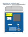
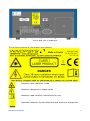
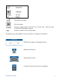
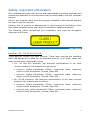
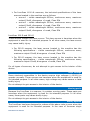
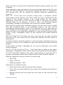
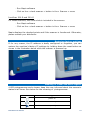
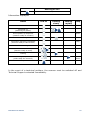
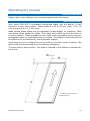
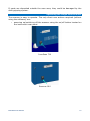
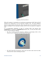
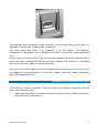
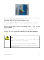
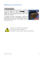
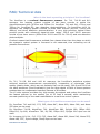
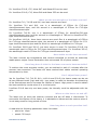
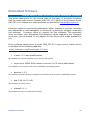
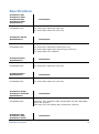
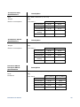
User manual PAGE FINDER IDENTIFICATION AND CERTIFICATION LABEL 3 SAFETY IMPORTANT INFORMATION 6 LASER SAFETY HIGH VOLTAGE MOVING PARTS SAFETY SYSTEM 6 7 7 7 USE TERMS 10 THE INNOSCAN SERIES 11 INSTALLING THE SCANNER 12 LIST OF PACKAGED COMPONENTS ELECTRICAL COMMUNICATION CONNECTION INSTALLING THE SCANNER SCANNER CHECK AFTER INSTALLING THE SCANNER RESTORING FACTORY SETTINGS MEANING OF VISUAL AND AUDIO SIGNALS 12 12 12 13 14 14 OPERATING THE SCANNER 16 USING THE SOFTWARE MICROSCOPE SLIDES OPERATING THE SINGLE SLIDE SCANNER OPERATING THE AUTOLOADER SCANNER SCANNER SELF-TESTS AND CHECKS INITIALIZATION CHECKS SCAN CHECKS INNOPSYS SLIDE CHECK 16 16 17 19 22 22 22 22 MAINTENANCE AND SERVICE 24 TROUBLESHOOTING 25 FAQ: TECHNICAL DATA 26 EMBEDDED FIRMWARE 30 SOURCE CODE OF PARTS OF THE INNOSCAN EMBEDDED FIRMWARE 30 SPECIFICATIONS 31 DECLARATION OF CONFORMITY 36 TECHNICAL SUPPORT 37 InnoScan user manual 2 Identification and Certification Label Two labels are affixed at the rear of the InnoScan as show on the picture below. 710 and 710-IR scanners InnoScan user manual 3 300-R and 300-G scanners The following pieces of information are present: Attention laser radiation inside Attention dangerous voltage inside Attention read carefully instructions for use Separate collection for the electrical and electronic equipment InnoScan user manual 4 Manufacturing date Serial number Scanner model (300-R, 300-G 710, 710-IR, 910, 1100 AL, with or without Autoloader system) Version number of the instrument Pictograms are associated to each connector to explain its function: RS232 port used for diagnostic issue Ethernet RJ45 port Alternating current Current & rating of fuse to be replaced InnoScan user manual 5 Safety: important information Only qualified personnel who knows and understands the safety warnings and precautions described in this document may be authorized to use the InnoScan scanner. Use for any purpose other than the purpose indicated in this manual exposes the user to serious hazards. Caution, use of controls or adjustments or performance of procedures other than those specified herein may result in hazardous radiation exposure. The following safety precautions are compulsory and must be stringently observed at all times. Laser Safety InnoScan 710, 710-IR, 910,1100 AL These devices contain two laser sources. These laser sources are harmless when the equipment is used for its intended purpose. In all other cases, the laser sources may cause bodily injury. For 710 and 910 scanners, the technical specifications of the laser sources located in the machine are as follows: • source1: visible wavelength 635nm, continuous wave, maximum output 15mW, divergence <1mrad, Class IIIb • source2: visible wavelength 532nm, continuous wave, maximum output 15mW, divergence <1mrad, Class IIIb For 710-IR scanners, the technical specifications of the laser sources located in the machine are as follows: • source1: visible wavelength 670nm, continuous wave, maximum output 15mW, divergence <1mrad, Class IIIb • source2: non visible wavelength 785nm, continuous wave, maximum output 25mW, divergence <1mrad, Class IIIb InnoScan user manual 6 For InnoScan 1100 AL scanners, the technical specifications of the laser sources located in the machine are as follows: • source1 : visible wavelength 635nm, continuous wave, maximum output 15mW, divergence <1mrad, Class IIIb • source2 : visible wavelength 532nm, continuous wave, maximum output 15mW, divergence <1mrad, Class IIIb • source3 : visible wavelength 488nm, continuous wave, maximum output 15mW, divergence <1mrad, Class IIIb InnoScan 300-R and 300-G These devices contain one laser source. This laser source is harmless when the equipment is used for its intended purpose. In all other cases, the laser source may cause bodily injury. For 300-R scanner, the laser source located in the machine has the following specifications : visible wavelength 635nm, continuous wave, maximum output 15mW, divergence <1mrad, Class IIIb For 300-G scanner, the laser source located in the machine has the following specifications : visible wavelength 532nm, continuous wave, maximum output 15mW, divergence <1mrad, Class IIIb For all types of scanners, do not attempt to gain access to the interior of the device. High voltage Some electronic assemblies in the device require high voltages (>1000V) to operate normally. These sources are harmless when the equipment is used for its intended purpose. In all other cases, high voltage may cause severe or fatal bodily injury. Do not attempt to gain access to the interior of the device. Moving parts Because the InnoScan is a scanner, it contains moving parts. These parts are harmless when the equipment is used for its intended purpose. In all other cases, these parts may cause bodily injury. Do not attempt to gain access to the interior of the device. Safety system The InnoScan has been designed to reduce all the above risks to zero when the equipment is used for its intended purpose. In the case of Innoscan single InnoScan user manual 7 slide, the device housing and its mechanical shutter system protects you from all danger. Never attempt to open the housing. No user-serviceable parts inside. The user must call Technical Support if the machine exhibits any failure or malfunction. The housing may only be opened by qualified personnel appointed by Innopsys. With 710, 710-IR and 910 Innoscan single slide a protective shutter obstructing the slide insertion port closes when the slide is swallowed by the scanner. If this shutter remains in the closed position for any reason whatsoever, preventing you from inserting a slide or removing a previously inserted slide, do not attempt to force it open: call Technical Support immediately. Damage to this shutter may expose you to laser hazards. With InnoScan equiped with AutoLoader system, the user has to close a sliding door after inserting slides in the autoloader system. This door will be automatically locked during a scan. Do not attempt to force it open during a scan. Damage to this sliding door may expose you to laser hazards. If for any reason the door is still locked after scanning or if you are able to open the door during a scan, immediately switch off the machine and contact Technical Support. With 300-R and 300-G InnoScan, the user must close the door after inserting the slide. If the user opens the door during the reading, the laser source is switched off. If a slide is broken inside the scanner or cannot be easily extracted, do not try and get it by force, do not attempt to open the housing but contact Technical Support. If the scanner housing is damaged, do not use the equipment and contact Tecfnical Support. For 710, 710-IR, 910 and 1100 AL , if any laser light is visible for any reason whatsoever, immediately switch off the machine and contact Technical Support. For 300-R and 300-G scanner, if the laser remains switch on when the door is opened, immediately switch off the machine and contact Technical Support. Warning, replace the fuse by a fuse of the same type • 2AT, 250V, • Type: 5*20 mm • Breaking capacity: 150A Instructions to replace the fuse: • Disconnect power cable and switch off the scanner • Turn a 5.5 mm plat screwdriver from right to left inside the fuse holder to remove it • Replace the fuse and move back the fuse holder on the rear side of the scanner InnoScan user manual 8 • Turn the screwdriver from left to right inside the fuse holder to lock it InnoScan user manual 9 Use terms The scanner is designed for use in research only. It is not designed or certified for use in the diagnosis of human or animal diseases. InnoScan user manual 10 The InnoScan series The range Innoscan includes nine different models: • InnoScan710 has excitation lasers with wavelengths 635nm and 532nm. It is able to scan slides with a 3 µm pixel size • InnoScan710-IR has excitation lasers with wavelengths 670nm and 785nm. It is able to scan slides with a 3 µm pixel size • InnoScan910A has excitation lasers with wavelengths 635nm and 532nm. It is able to scan slides with a 1 µm pixel size • InnoScan300-R, a scanner with wavelength 635nm. It is able to scan slides with a 10µm pixel size. • InnoScan300-G, a scanner with wavelength 532nm. It is able to scan slides with a 10µm pixel size. • InnoScan710AL is an InnoScan710 scanner associated with a 24 slides loader. • InnoScan710-IR AL is an InnoScan710-IR scanner associated with a 24 slides loader. • InnoScan910AL is an InnoScan910 scanner associated with a 24 slides loader as well. • InnoScan 1100 AL with a 24 slides loader, has excitation lasers with wavelengths 635nm, 532nm and 488nm. It is able to scan slides with a 0.5µm pixel size. InnoScan user manual 11 Installing the scanner List of packaged components • scanner • mains power cable • ethernet crossover cable STP (Shielded Twisted Pairs) • user manual • software installation CD • software user manual • Innopsys check slide for 710, 710-IR, 910 and 1100 AL scanners Electrical Communication Connection Before you connect the scanner to your electrical communication, please ensure that : • the wall socket is grounded, • your electrical communication follows these specifications: • Power supply: 100-240 V / 47-63 Hz • Fuse: 4A at 110V / 2A at 220V • Electrical communication: circuit breaker able to switch at least in 40ms. Without a grounded socket and/or if your electrical circuit does not comply with these specifications, the equipment should be damaged and the user's safety should not be ensured. Installing the scanner The scanner must be located on a base: • not subject to strong vibrations (centrifuge, vortex, etc.) • not exposed to direct sunlight • that prevents the housing from coming into any contact with chemicals (especially acetone) • Block scanner ventilation, allow 5 cm of space from the rear panel of the scanner • Move the scanner while it is functioning. Remove any slide from inside of the scanner before moving it. If necessary, ask for colleague assistance to move the scanner • Put the scanner on a table strong enough to bear the weight of the scanner InnoScan user manual 12 Connect the scanner to a grounded mains outlet (110V or 220V) by using the mains power cable supplied. Connect the scanner to a dedicated PC via the crossover ethernet cable supplied, or to the network via a STP (Shielded Twisted Pairs) straight ethernet cable . Change the IP address and the various network parameters of the scanner as required for your network (ask your network administrator for advice). To do this, enter the scanner's default address (192.168.0.254) in your web browser's navigation bar. This will connect you to the machine's web server: Click on Network: you may now edit the machine's network parameters: To confirm your parameters, click on "Validate the configuration". Press "Reset" to cancel changes. To configure the scanner as a DHCP client, type 0.0.0.0 as IP Address. Scanner check after installing the scanner InnoScan 710, 710-IR, 910 and 1100 AL - Insert the delivered check slide InnoScan user manual 13 - Run Mapix software - Click on the « check scanner » button in the « Scanner » menu InnoScan 300-R and 300-G For these scanners, the check slide is included in the scanner. - Run Mapix software - Click on the « check scanner » button in the « Scanner » menu Mapix displays the checked points and if the scanner is functionnal. Otherwise, please contact your distributor. Restoring factory settings If for any reason, the IP address is badly configured or forgotten, you can restore the machine's factory IP settings by holding down the reset button as shown in the illustration below while the scanner is powered up. Meaning of visual and audio signals 4 LED pictogrammes and a buzzer keep the user informed about the scanner's status at all times. See below for the meaning of pictogrammes: Meaning of icon power on connecting microarray read/present InnoScan user manual 14 Meaning of icon technical problem Information displayed: status LED on flashing slowly flashing rapidly beep scanner on powering up (switching on power) end of power-up sequence (scanner ready to connect) short connecting connection sequence completed (scanner ready to take a slide) long disconnecting short slide inserted (scanner ready to read) reading reading completed (slide ready for removal) 3 shorts technical problem In the event of a technical problem, the scanner must be switched off and Technical Support contacted immediately. InnoScan user manual 15 Operating the scanner Using the software Please refer to the software user manual supplied with the device. Microscope Slides Only insert ISO 8037/1-compliant microscope slides into the device, to the exclusion of any other object. These slides are 25 to 26 mm wide, 75 to 76 mm long and 0,9 to 1,2 mm thick. Make certain these slides are not damaged (chiped edges, for instance). Take care about labels sticked on slides. They have not to stick up from the slide or to come unstuck. These precautions are of the most importance when using an autoloader system in association with InnoScan. The edges of the slides should be reflective to be detected by the autoloader system. Verify that there is no safety film on the slide or any other sticky material. The slide could not be removed from the scanner otherwise. The scan area is shown below. The slide is inserted in the direction indicated by the arrow: * * 1.85mm for InnoScan910 or InnoSCan910AL InnoScan user manual 16 If spots are deposited outside the scan area, they could be damaged by the slide gripping system. Operating the single slide scanner The scanner is easy to operate. The only direct user actions required (without using the software) are: • powering up/switching off the scanner using the on/off button located on the instrument rear panel. InnoScan 710 Scanner 910 InnoScan user manual 17 Scanners 300-R et 300-G When the scanner is powered up, it performs a sequence of self tests and will indicate any malfunction via the Technical Problem LED. The test sequence lasts for approximately 30 seconds. When the sequence has completed, a short beep is emitted. If the Technical Problem LED is off, the scanner is ready for use. It is nevertheless advisable to wait 10 minutes after the scanner has connected (as opposed to powered up) before use, so that the lasers have time to achieve thermal stability. • For 710, 710-IR and 910 scanners, placing a microscope slide in the insertion port located on the instrument front panel. • For 300-R and 300-G scanners, open the front door and insert the slide. Close the door before starting the scan. InnoScan user manual 18 Scanners 300-R et 300-G The barcode and microarray spots must be on the same face of the slide, i.e. upwards, as shown in the previous illustration. Two rails guide the slide in by gripping it by the edges. The insertion mechanism is designed not to damage the slide or the array spots deposited on it. Gently push the slide home. The microarray presence detector detects that a slide has been inserted and the microarray present LED comes on, indicating that the scanner is ready to read the sample. Any other use of the scanner may be dangerous, or may harm the scanner. Do not attempt to loosen screws or insert any object other than slides complying with ISO standard 8037/1. Operating the autoloader scanner The scanner is easy to operate. The only direct user actions required (without using the software) are: • powering up/switching off the scanner using the on/off button located on the instrument rear panel. InnoScan user manual 19 Scanner 710AL Scanners Innoscan 910AL, InnoScan 1100 AL When the scanner is powered up, it performs a sequence of self tests and will indicate any malfunction via the Technical Problem LED. The test sequence lasts for approximately 30 seconds. When the sequence has completed, a short beep is emitted. If the Technical Problem LED is off, the scanner is ready for use. It is nevertheless advisable to wait 10 minutes after the scanner has connected (as opposed to powered up) before use, so that the lasers have time to achieve thermal stability. • Slid down the door until full opening. Insert slides horizontally in the loader slots numbered from 1 to 24. Gently push them until they reach the stop. InnoScan user manual 20 The barcode and microarray spots must be on the same face of the slide, i.e. upwards, as shown in the previous illustration. Gently slide up the door to close the autoloader system. The microarray presence detector detects that a slide has been inserted and the microarray present LED comes on, indicating that the scanner is ready to read the sample. During a scan the door is locked. Do not attempt to force it open, you may harm the scanner. Wait for the end of the scans – see chapter «Meaning of visual and audio signals » before sliding down the door and getting back the slides. Any other use of the scanner may be dangerous, or may harm the scanner. Do not attempt to loosen screws or insert any object other than slides. Be sure that inserted slides complied with ISO standard 8037/1(see chapter Microscope Slides) Be sure that inserted slides are pushed until the end stop Be sure that inserted slides are horizontal and not inserted on two different levels. InnoScan user manual 21 Scanner self-tests and checks The scanner runs three levels of self-tests and checks. Initialization checks When the scanner is powered up, the LEDs light up as indicated in the chapter Meaning of visual and audio signals. Moving parts, detectors, laser power and the Ethernet port are all checked. If an error is detected, three long beeps sound and the red LED indicating a technical problem lights up. If this happens, switch off the scanner immediately and contact Technical Support. Scan checks During slide scanning, laser power and the autofocus are checked constantly. The scanner will report if either of these servo-controls did not function correctly, as this can produce errors. If such errors keep recurring, refer to the Troubleshooting chapter. Innopsys with slide check You can also check the scanner more precisely if you so wish. 710, 710-IR, 910 and 1100 AL scanners Insert the Innopsys slide provided with your scanner and run a check from the Scanner->Check scanner menu in Mapix. The fluorescence signal, image red/green shift (710, 910), image red/infrared shift (with 710-IR) or image red/green shift – red/blue shift (with 1100 AL) and detection gain linearity are all checked. For 710, crosstalk is also checked. The fluorescence signal and image shift are compared to a reference value and to values obtained when the last check was run. A data integrity check is also performed. The scanner indicates any malfunction detected. In this case, contact Technical Support. The slide supplied with your scanner is valid for one year. The software will no longer allow you to run checks with it beyond this date and you must procure a new one. The slide must be stored in its box at room temperature and away from light when not being used. You are advised to check the scanner once a month or each time you move it. Only use this slide with the scanner it was delivered with. InnoScan user manual 22 300-R and 300-G scanners For these scanners, the check slide is already included in the scanner. The user runs a check directly from the Scanner->Check scanner menu in Mapix. The fluorescence signal and detection gain linearity are checked. The fluorescence signal is compared to a reference value and to values obtained when the last check was run. A data integrity check is also performed. The scanner indicates any malfunction detected. In this case, contact Technical Support. The slide included in the scanner is valid for 3 years. Beyond this date, the slide has to be changed. InnoScan user manual 23 Maintenance and Service Fan filter replacement: For models equipped with a fan filter, it is necessary to replace the filter by a new one every year. In the event of failure to meet the deadline for replacement of the filter, the scanner warranty deed should be revoked. Customer has to order a new filter to its distributor. To replace the filter (see picture), remove the protection grid which is interlocked at the back of the scanner, remove the old filter, place the new filter and then interlock the protection grid by pressing each side. No other user maintenance is required. No other user service is allowed. If a problem occured, please contact your distributor. InnoScan user manual 24 Troubleshooting Sympton The image is dark or the measured signal is weak Diagnosis • • • • For scanners 710, 710-IR and 910 and 1100 AL: the image is striped or Mapix displays a « Focus was not stable during the scan » message • • • • The image is distorted and shapes are the wrong size • • • There is a spot in the same place on all images, whatever slide you use. InnoScan user manual • • Make sure the detector gain is not too low (set to 100% to check) If laser power is adjustable, make sure the laser power settings are not too low (set to high to check) Make sure the slide fluorescence marking is compatible with InnoScan (see list of supported fluorophores in FAQ: Technical Data) Check the scanner using the Innopsys-supplied slide (see Scanner self-tests and checks) The autofocus may not work properly with certain types of slide. It needs a clean reflective surface. A large bar code may cause problems. You can set the bar code height in Mapix (see your Mapix manual). Certain types of slide (e.g. with black edges) may also cause problems. You can select the slide type in Mapix (see your Mapix manual). Thick spots deposited around the edges of the scan area may also confuse the autofocus system. Contact Technical Support to try to resolve the problem. Otherwise, you can deactivate the autofocus. See previous problem in the case of 710, 710-IR, 910 and 1100 AL scanners. Check if the same problem occurs with all types of slides. Check that the problem isn’t being caused by the direction in which the slide is inserted by turning it around 180° and then reinserting it. If the defects are also rotated 180°, the slide is causing the problem. Otherwise, contact Customer Support. Contact Customer Support. Avoid using slides with liquids likely to run during scanning. 25 FAQ: Technical data What is the basic operating principle of the InnoScan? The InnoScan is a confocal fluorescence scanner. For 710, 710-IR and 910 scanners, the imaging system consists of two laser sources to excite the chemifluorescent dyes (635nm and 532nm for InnoScan 710 and 910, 670nm and 785nm for InnoScan-IR), two detection photomultipliers. For InnoScan 1100 AL scanners, the imaging system consists of three laser sources (635nm, 532nm and 488nm) and three detection photomultipliers. A very high-precision optical filters provide results with enhanced signal-to-noise ratios. 300-R and 300-G scanners consist of one laser source (635nm for 300-R and 532 for 300-G) and one detection photomultiplier. Confocal means that fluorescence emitted from planes other than the plane on which the scanner's optical system is focussed is not measured, thus cancelling out all parasite fluorescence. For 710, 710-IR, 910 and 1100 AL scanners, the InnoScan's autofocus system achieves excellent measurement reproducibility, irrespective of microscope slide quality (plastic slides, which are not perfectly flat, can be used). 300-R and 300-G do not have autofocus (fixed focalization) but the large depth of field of these systems enables them to compensate imperfect flatness of the slides. The XY drive system provides very high sample throughput and makes the InnoScan the fastest scanner on the market (up to 35 lines a second) while maintaining accurate positioning of the read head thanks to a real-time control system. What types of chemifluorescent dyes can be used? For InnoScan 710 and 910, CY3, CY5, Alexa 647, Alexa 660, Alexa 546, and Alexa 555 dyes can be used. For InnoScan 710-IR, AlexaFluor 700, AlexaFluor 680, Dylight 680, IRDye 680, IRDye700, Dy-680, AlexaFluor 790, Dy-780, IRDye 800, Dylight 800 dyes can be used. For Innoscan 1100 AL, Cy2, CY3, CY5, Alexa 647, Alexa 660, Alexa 546, Alexa 555, Alexa 488, FITC, Sytox orange, Draq5 dyes can be used. InnoScan user manual 26 For InnoScan 300-R, CY5, Alexa 647 and Alexa 660 can be used. For InnoScan 300-G, CY3, Alexa 546 and Alexa 555 can be used. What are the wavelengths of the laser sources? For InnoScan 710, 710-IR and 910, two laser sources are used. For InnoScan 710 and 910, one is a wavelength of 635nm for CY5-type chemifluorescent dyes, and the second is a wavelength of 532nm for CY3-type chemifluorescent dyes. For InnoScan 710-IR, one is a wavelength of 670nm for AlexaFluor700-type chemifluorescent dyes, and the second is a wavelength of 785nm for AlexaFluor790type chemifluorescent dyes. For InnoScan 1100 AL, three laser sources are used. One is a wavelength of 635nm for CY5-type chemifluorescent dyes, the second is a wavelength of 532nm for CY3type chemifluorescent dyes and the third is a wavelength of 488nm for CY2-type. For InnoScan 300-R and 300-G, one laser source is used. For InnoScan 300-R, the wavelength used is 635nm for CY5-type chemifluorescent dyes. For InnoScan 300-G, the wavelength used is 532nm for CY3-type chemifluorescent dyes. How stable are the laser sources? The laser sources are temperature and current-controlled to provide an extremely stable power output. Power fluctuation does not exceed 2% of power output. How long does it take for the laser sources to become stable? To achieve the most accurate results, you are advised to wait 10 minutes after the scanner has connected. The lasers will have reached their stable nominal operating temperature by then. Can I adjust laser power? Yes for InnoScan 710, 710-IR, 910, 1100 AL and 300-G, the lasers power can be set at two different levels (high and low). Low power is useful to decrease the bleaching of the fluorophores and to increase the lifetime of lasers. High power is used to obtain the best sensitivity results when it is a critical point. InnoScan 300-R has only one laser power, the intensity could be adjustable with the gain. When are the lasers on and off? The lasers are on when the scanner connects and are off when it disconnects. To economize the lifetime of the lasers, it is advisable to disconnect the scanner when it is not being used for long periods of time. How long does a read operation last? A read with the following parameters lasts 4 minutes: • pixel size: 10µm • speed: 35 lines/s InnoScan user manual 27 • read area: full slide Can I adjust the scanning speed? Yes, scan speed is adjustable from 10 lines/s to 35lines/s What happens when I change the scanning speed? Reducing scanning speed provides a better signal-to-noise ratio, which can be useful in applications characterised by low fluorescence. Can I adjust pixel size? Yes, pixel size can be adjusted from 10 to 40µm with InnoScan 300-R and InnoScan 300-G, from 3 to 40µm with InnoScan710 and InnoScan710-IR, from 1 to 40µm with InnoScan910 and from 0.5 to 40µm with InnoScan 1100 AL. The memory size of a full slide image acquired at a pixel size of 5µm saved to a tiff file is approximately 256Mb. What happens when I change pixel size? If you reduce pixel size, you obtain better resolution but a larger image file and you have to ascertain whether the PC is capable of handling files this big. For instance, a full slide image at a pixel size of 5µm requires at least 2Gb of RAM. What detection method is used? We use photomultipliers because it provides results with better signal-to-noise ratios thanks to very low background noise and high sensitivity. Can I adjust detection gain? Yes, detection gain may be modified from 0% to 100%. The gain variation is linear allowing the user to adjust this setting very precisely. It may be useful to cancel out saturation or to equalize channels for instance. What is the accuracy of the mechanical positioning system? The scanner features a high-precision mechanical positioning system based on a patented real-time control loop. Absolute positioning is typically 30µm over the entire slide with InnoScan300-R and 300-G, 10 µm with InnoScan710 and InnoScan710-IR and 4µm on a 22mmx22mm scanned area on InnoScan910 and InnoScan 1100 AL. InnoScan user manual 28 Which barcodes can the scanner read? The scanner is capable of reading all these symbologies: • • • • • • • • • • • • • • • • • codabar code39 Interleaved 2 of 5 code93 code 2 of 5 iata code 2 of 5 matrix 2 of 5 code11 code128 telepen upcA-E0-E1 eanJAN13/JAN8/UCC msi plessey rss-14/limited/expanded china post code pdf417 InnoScan user manual 29 Embedded firmware Source code of parts of the InnoScan embedded firmware This is the description for the source code of the parts of InnoScan firmware that fall under open source licenses GNU GPL v2.0. Parts of the firmware under GNU GPL v2.0 license are made available on demand at [email protected]. Innopsys makes no warranties whatsoever either express or implied, including any warranties of merchantability or fitness for a particular purpose, regarding this software. Innopsys offers no support for this software. The preceding does not affect your warranties and statutory rights regarding any Innopsys product(s) you purchased. It only applies to this source code made available to you. Every software listed below is under GNU GPL V2.0 open source license which is available at the following address: http://www.gnu.org/licenses/gpl-2.0.html u-boot 1.2.0 and modifications This software is used to initialise and to launch the system noyau linux DENX-ELDK based on kernel 2.4.25 and modifications This software is the kernel of the linux embedded operating system busybox 1.2.1 This software provides a fairly complete environment for any small or embedded system boa 0.94.14-0.5.rc21 This software is a http server eraseall 0.1.0 This software is used to erase flash memory InnoScan user manual 30 Specifications InnoScan 710A InnoScan 710AL InnoScan 910A InnoScan 910AL Specifications Description Excitation wavelengths 635 nm and 532 nm Compatible dyes Cy5, Alexa 647, Alexa 660 (635 nm) Cy3, Alexa 546, Alexa 555 (532 nm) InnoScan 1100 AL Specifications Description Excitation wavelengths 635 nm, 532 nm et 488nm Compatible dyes Cy5, Alexa 647, Alexa 660, Draq5 (635 nm) Cy3, Alexa 546, Alexa 555, Sytox orange (532 nm) Cy2, Alexa 488, FITC (488nm) InnoScan 300-R Specifications Description Excitation wavelength 635 nm Compatible dyes Cy5, Alexa 647, Alexa 660 (635 nm) InnoScan 300-G Specifications Description Excitation wavelength 532 nm Compatible dyes Cy3, Alexa 546, Alexa 555 (532 nm) InnoScan 710-IR InnoScan 710-IR AL Specifications Description Excitation wavelengths 670 nm and 785 nm Compatible dyes AlexaFluor 700, AlexaFluor 680, Dylight 680, Dy-680, IRDye680, IRDye 700 (670nm) Alexa 790, Dye-780, IRDye 800, Dylight 800 (785nm) InnoScan 710A InnoScan 710AL InnoScan 710-IR InnoScan user manual Description 31 InnoScan 710-IR AL InnoScan 300-R InnoScan 300-G Specifications Laser Power Adjustable (2 laser powers available excepted for 300-R which has a fixed laser power) PMT Gain Adjustable from 0 to 100% Autofocus Real time autofocus Detection Real confocal and high performances PMT Dynamique Range Over than 104 Uniformity Lower than 5% CV Sample All standard microscope slide Width: 25-26 mm Length: 75-76 mm Thickness: 0,9-1,2 mm Max. Scanning Area 22 x 74 mm Scan Speed Adjustable from 10 to 35 lines/second Scanning Time 3,5 minutes with a scan area of 22x74mm with a 10µm pixel size for a 1 or 2 color simultaneous acquisition. Barcode Codabar, code39, Iinterleaved 2 of 5, code93, code 2 of 5, iata code 2 of 5, matrix 2 of 5, code11, code128, telepen, upcA-E0-E1, eanJAN13/JAN8/UCC, msi, plessey, rss-14/limited/expanded, china post code, pdf417 Interface Ethernet Operating condition Temperature : From 19 °C to 26°C Humidity : 20 – 95% HR Altitude : 0 - 2300 m InnoScan 910 InnoScan 910AL Innoscan 1100 AL Specifications Description Laser Power Adjustable (2 laser powers available) PMT Gain Adjustable from 0 to 100% Autofocus Real time autofocus Detection Real confocal and high performances PMT Dynamique Range Over than 104 Uniformity Lower than 5% CV InnoScan user manual 32 Sample All standard microscope slide Width: 25-26 mm Length: 75-76 mm Thickness: 0,9-1,2 mm Max. Scanning Area 22 x 74 mm Scan Speed Adjustable from 20 to 35 lines/second (max 25 lines/second with a 0.5µm pixel size) Scanning Time 3,5 minutes with a scan area of 22x74mm with a 10µm pixel size for a 1, 2 or 3 color simultaneous acquisition. Barcode Codabar, code39, Iinterleaved 2 of 5, code93, code 2 of 5, iata code 2 of 5, matrix 2 of 5, code11, code128, telepen, upcA-E0-E1, eanJAN13/JAN8/UCC, msi, plessey, rss-14/limited/expanded, china post code, pdf417 Interface Ethernet Operating condition Temperature : From 19 °C to 26°C Humidity : 20 – 95% HR Altitude : 0 - 2300 m InnoScan 710A InnoScan 710AL InnoScan 710-IR InnoScan 710-IR AL Specifications Description Optical resolution 2.7 µm (635 nm – spot diameter FWHM) 3 µm (670nm – spot diameter FWHM) Pixel Resolution From 3 to 40 µm InnoScan 910 InnoScan 910AL Specifications Description Optical resolution < 0.6µm (635-532 nm – spot diameter FWHM) Pixel Resolution From 1 to 40 µm Spécifications InnoScan 1100 AL Description Optical resolution < 0.6µm (635-532-488 nm – spot diameter FWHM)) Pixel Resolution From 0.5 to 40 µm InnoScan 300-R InnoScan 300-G Specifications InnoScan user manual Description 33 Optical resolution 10 µm (532nm – spot diameter FWHM) Pixel Resolution From 10 to 40 µm InnoScan 710A InnoScan 710-IR Specifications Description Size 278 x 457 x 369 mm (L x P x H) Weight 15,5 Kg Electric consumption 100-240 V InnoScan 910 Specifications 220 V 110 V Initialization 41 W 30 W Stand by 30 W 20 W Connected 32 W 24 W Barcode reading 35 W 26 W Scan 33 W 25 W Description Size 316 x 549 x 432 mm (L x P x H) Weight 28 Kg Electric consumption 100-240 V InnoScan 710AL InnoScan 710-IR AL Specifications 220 V (230 V) 110 V (124 V) Initialisation 42 W 42 W En attente 43 W 37 W Connecté 36 W 38 W Lecture CAB 39 W 38 W Lecture lame 39 W 40 W Description Size 333 x 595 x 422 mm (L x P x H) Weight 27Kg Electric consumption InnoScan user manual 100-240 V 220 V 110 V Initialization 37 W 20 W Stand by 40 W 31 W Connected 35 W 27 W Barcode reading 35 W 26 W Scan 33 W 25 W 34 InnoScan 910AL Specifications Description Size 322 x 656 x 439 mm (L x P x H) Weight 33Kg Electric consumption 100-240 V InnoScan 1100 AL Specifications 220 V (230V) 110 V (124V) Initialization 45 W 45 W Stand by 40 W 40 W Connected 41 W 41 W Barcode reading 44 W 44 W Scan 45 W 45 W Description Size 322 x 656 x 439 mm (L x P x H) Weight 35Kg Electric consumption 100-240 V InnoScan 300-R InnoScan 300-G Specifications 220 V (230V) 110 V (124V) Initialization 46 W 45 W Stand by 43 W 41 W Connected 45 W 45 W Barcode reading 47 W 45 W Scan 48 W 47 W Description Dimensions 344 x 426 x 163 mm (L x P x H) Poids 11Kg Puissance InnoScan user manual 100-240 V 220 V (230 V) 110 V (124 V) Initialisation 30 W 29 W En attente 20 W 18 W Connecté 21 W 20 W Lecture CAB 25 W 25 W Lecture lame 25 W 24 W 35 Declaration of conformity InnoScan user manual 36 Technical support Parc d'Activités Activestre 31 390 Carbonne - France Phone: +33 561 971 974 Email: [email protected] InnoScan user manual 37 Function Written by : Approved by : InnoScan user manual R&D department Quality manager Signature JULIEN CALVE Signature numérique de JULIEN CALVE DN : cn=JULIEN CALVE, o=Innopsys, ou=recherche et developpement, [email protected], c=FR Date : 2014.07.03 14:34:03 +02'00' Celine Hardy cn=Celine Hardy, o=Innopsys, ou=Responsable Qualite et affaires reglementaires, [email protected], c=FR 2014.07.03 17:15:13 +02'00' 38 www.innopsys.fr Originale instruction version: 3.4.1 InnoScan user manual 39