1
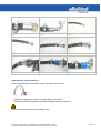
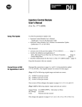
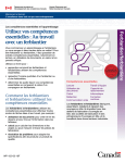
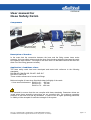
User manual for
Hose Safety Catch
Components
Hose clamp (with
elastomer insert)
Wire
guide
Catch
wire
Velcro
strap
Fixing bracket
Description of function
In the event that the connection between the hose and the fitting comes loose under
pressure, the hose safety wire prevents the hose from throwing (whipping) because the catch
wire tightens under tension. The length of the catch wire is to be laid out so that the hose can
slide out of the fitting (pressure release).
Application / Conditions of use
The hose safety catch has been developed and tested with reference to the following
standards:
DIN EN 853, DIN EN 856, EN 857, SAE J517
DIN 2353, SAE J518
These contain references to hoses and fittings.
Minimum lengths of hose when fitted both sides (left/right) of the catch:
Hose nominal diameters DN 06 to 31: 600 mm
DN 38 to 51: 700 mm
DN 60 to 76: 1000 mm
It is essential to ensure that the use complies with these standards. Guarantee claims are
invalid when these assembly instructions are not complied with. The maximum operating
pressure of the hose must not be exceeded. In case of use at higher operating pressures,
no liability will be accepted for sufficient strength of the system.
Dipl. Ing. K. Dietzel GmbH, Leedenstraße 10, 04626 Beerwalde, Germany
Translation of the German original instructions for use (version: 31.03.2014)
page 1 / 4
Please note the following for the use of the hose safety catch in an environment subject to
risk of fire or explosion:
The hose safety catch components are made of metallic material. Die risk of sparking is very
low, but generally given.
A minimum spacing between hoses under pressure is still required when using the hose
safety catch, because the length of the catch wire is designed so that pressure can be
released in case of damage (see description of function).
Recommended minimum separation: 0.5 m
Installation / Assembly
The hose safety catch consists of many single parts, which are fitted together on the hose by
technicians to form the safety device.
Make sure before starting assembly that the hose system is not under pressure. Observe the
following assembly instructions.
Assembly instructions
• Select the correct fixing elements.
• Position the wire guide on the hose with the hose clamp
• Set the spacing to 45 mm between hose clamp and the end of the ferrule [Fig. 1]. If the
fitting has an elbow, you must also take the position of the wire guide to the pipe bend
into account [Fig. 2].
• Tighten the bolt on the clamp until the rubber insert (elastomer profile) is secure on the
hose, but still allows the hose to swell according to the permissible operating pressure.
• Lay the catch wire on the hose [Fig. 3]. Take the ends of the wire and lead them under
the hose so that the wires cross. This forms a loop [Fig. 4]. Then insert the ends of the
wire through the large hole in the wire guide. This produces another crossing point [Fig.
5].
• Before fitting the standard fixing bracket on a DKO connection, you must insert the ends
of the wire into the slot [Fig. 6]. Using the two-piece version, the assembly can be done
afterwards [Fig. 7]. The torques of the fixing bolts is 6,0Nm for thread M5 and 10,0Nm for
M6 thread.
• After the assembly of the bracket, secure the catch wire with a Velcro band to the ferrule
[Fig. 8].
• The assembly to a hose with a SAE flange is analogous to a DKO fitting [Fig. 9].
When using fittings from other suppliers, you need to assure that the free distance between
end of nut and the counterpart is big enough for the fixing plate. The plate may not be
jammed to ensure the sealing of the hydraulic fitting.
Dipl. Ing. K. Dietzel GmbH, Leedenstraße 10, 04626 Beerwalde, Germany
Translation of the German original instructions for use (version: 31.03.2014)
page 2 / 4
Fig. 1
Fig. 2
Fig. 3
Fig. 4
Fig. 5
Fig. 6
Fig. 7
Fig. 8
Fig. 9
Operational safety notices
When assembling the hose safety catch onto hoses which move
gg
• Rubbing or grazing to the skin through safety components
• Pinching of hands (fingers) through the changing position of the wire
Practice increased caution in the danger area.
Dipl. Ing. K. Dietzel GmbH, Leedenstraße 10, 04626 Beerwalde, Germany
Translation of the German original instructions for use (version: 31.03.2014)
page 3 / 4
Storage / Maintenance / Care
Store the assembled hose safety devices sorted in a dry place. Individual parts may not be
exchanged.
The hose safety catch itself is maintenance-free. When used in machines, test bays etc.,
where increased oscillation, vibration or pulsation of the hose can be expected, the hose
safety catch must be checked at regular intervals (e.g. with machine maintenance work) to
ensure the hose clamp is secure and does not have any damage.
In case of damage to individual parts, the entire hose safety catch must be replaced. The
same applies when the safety catch comes into action after the failure of a hose connection.
EC conformity declaration for machines (directive 2006/42/EC)
The manufacturer hereby declares…
Dipl. Ing. K. Dietzel GmbH, Leedenstraße 10, 04626 Beerwalde, Germany
that the safety device …
for the holding of a hose in case of failure “Hose Safety Catch” of type SD-XXXX1-XXX2SLXXXX3 und SF-XXXX1-XXX2-SLXXXX3
1
Clamping range of the hose clamp
Diameter of hole in the bracket
3
Wire length
2
conforms to the provisions of the above directive.
The following harmonised standards have been applied:
DIN EN ISO 12100, parts 1 and 2………………… Safety of machinery – basic terms
DIN EN ISO 14121-1……………………………... Safety of machines – risk evaluation
Name/address of the person responsible for documentation:
Nicky Groß, Design Department, Leedenstraße 10, 04626 Beerwalde, Germany
Dipl. Ing. K. Dietzel GmbH, Leedenstraße 10, 04626 Beerwalde, Germany
Translation of the German original instructions for use (version: 31.03.2014)
page 4 / 4