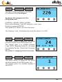
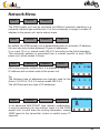
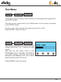
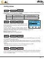
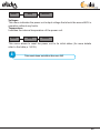
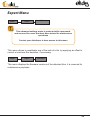
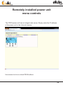
1
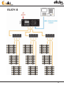
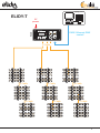
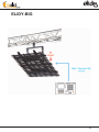
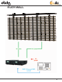
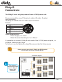
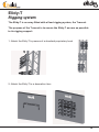
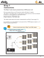
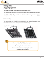
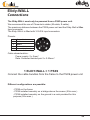
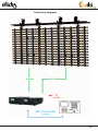
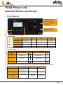
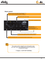
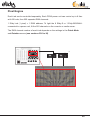
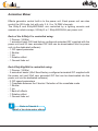
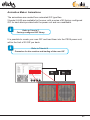
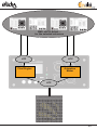
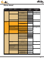
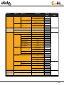
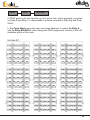
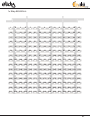
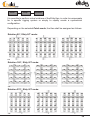
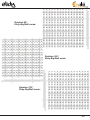
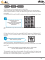
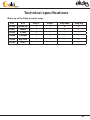
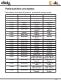
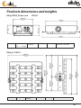
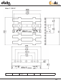
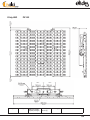
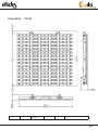
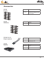
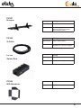
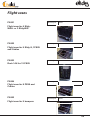
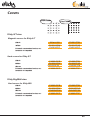
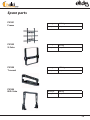
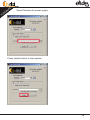
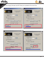
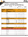
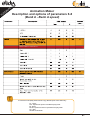
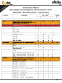
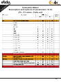
User Manual
V3.0 / Software V2.0
Elidy
Chromlech
19, avenue Gabriel Fauré
35235 THORIGNE-FOUILLARD
FRANCE
Tel: +33 2.23.20.77.67
Fax: +33 2.23.20.75.71
E-mail: [email protected]
Website: www.chromlech.com
Issue
Change
V2.0
Base
First issue: 12.11.20
12.11.22
V2.1
Lightened base
12.11.23
V2.2
Base for translation
12.11.25
V3.0
Firmware V2.0_EN
13.06.21
2
Elidy
Hello,
Thank you for using our equipment and for your confidence in us.
We endeavour to provide you with high quality equipment which is reliable and
easy to use and strive to meet your expectations.
If, however, you find defects or malfunctions, we will be very happy to resolve
any problems for you as quickly as possible.
This user manual relates to all products in the Elidy range.
For your safety, please read this manual carefully before using the equipment
for the first time.
If you have any questions or require additional information:
[email protected]
3
Elidy
4
Elidy
Table of contents
Safety guidelines and precautions for use...........................10
Elidy-S......................................................................................14
Rigging system.............................................................14
Connections...................................................................15
Elidy-T.......................................................................................16
Rigging system.............................................................16
Connections...................................................................17
Elidy-BIG..................................................................................18
Rigging system.............................................................18
Connections...................................................................19
Elidy-WALL...............................................................................20
Rigging system.............................................................20
Connections...................................................................24
PSX9 Power unit......................................................................26
Detail of buttons and menu..........................................26
Control............................................................................28
Sources and Controllers..............................................32
Menu detail....................................................................34
Patch Mode....................................................................36
Rotation..........................................................................38
Tile Mapping..................................................................40
Pixel Engine...................................................................44
Animation Maker...........................................................48
Network Menu................................................................52
Test Menu.......................................................................53
Utility menu....................................................................54
Expert Menu...................................................................56
Remotely installed power unit menu controls......................58
Technical specifications.........................................................60
Parts numbers and names...........................................61
Products dimensions and weights..............................62
Accessories...................................................................66
Flight cases...................................................................68
Covers............................................................................69
Spare parts....................................................................70
TUTORIALS..............................................................................72
WARRANTY..............................................................................90
5
Elidy
ELIDY-S
6
Elidy
Lighting Control
ELIDY-T
AC
power
elidy PSX9
PSX9
DMX / Ethernet DMX
control
S-Cable
S-Cable
S-Cable
S-Cable
S-Cable
S-Cable
S-Cable
7
Elidy
ELIDY-BIG
8
Elidy
ELIDY-WALL
9
Elidy
Safety guidelines and
precautions for use
!
!
For your safety and that of others, it is essential you read this manual
carefully and follow the instructions closely.
This equipment is reserved for professional use.
It is not intended for domestic use. This product can cause serious or
even fatal injuries by fire, electrocution and falling from height.
Only experienced and qualified users are allowed to install and use the
products in CHROMLECH’s ELIDY range.
Do not allow inexperienced persons to handle the products.
•••
Before using the equipment for the first time, ensure it has not suffered any
damage during transit. If so, DO NOT USE the equipment and contact your
CHROMLECH dealer.
•••
In all cases, always inspect the mechanical and electrical parts of ELIDY
equipment before fitting to check they are not damaged.
In particular, check the lifting points, locking pins and connectors.
If there is any doubt that one of these parts may be damaged or faulty, DO NOT
USE THE PARTS CONCERNED and contact your dealer.
•••
The manufacturer can not be held liable for damages caused by non-compliance
with safety, installation and fitting instructions contained in this manual or by
any modifications made to products in the ELIDY range.
Non-compliance with safety, installation and fitting instructions or any
modifications made to products in the ELIDY range will nullify the warranty.
•••
Products in CHROMLECH's ELIDY range comply with the EC standard.
10
Elidy
Electrical safety
!
RISK OF ELECTRIC SHOCKS. ALWAYS DISCONNECT EQUIPMENT
BEFORE HANDLING OR CARRYING OUT MAINTENANCE
•••
Check that your electrical installation complies with current standards.
•••
Always connect the product to electrical ground.
•••
The PSX9 power unit must be connected directly to the mains
(100-240 VAC~ / 50-60 Hz).
DO NOT CONNECT TO AN ELECTRONIC OUTPUT
(dimmer, solid-state relay, etc.)
•••
Do not connect any device other than the PSX9 power unit to the power supply
repeater socket.
•••
Ensure the repeater power supply is not overloaded (MAX 16 A).
•••
To ensure the PSX9 power unit operates satisfactorily, be careful not to obstruct
the ventilation grills.
•••
The ELIDY-S, WALL and BIG products need a hybrid power cable designed by
CHROMLECH to operate. This cable is not supplied with the product and is
available as an optional extra in a wide variety of lengths. Chromlech declines
any liability if other cables are used to operate products in the ELIDY range.
11
Elidy
Installation
Products must be installed according to "best practice" by qualified and certified
personnel.
•••
Installation personnel should wear statutory safety equipment while putting up
and taking down the system.
•••
Ensure that the public and personnel are prevented from passing underneath
the system while it is being rigged. The rigging area must be cordoned off and
inaccessible to the public.
•••
Never leave the system unattended
during installation.
•••
Do not allow anybody, whether stage hands, artists or members of the public, to
climb, jump or hang from products in the ELIDY range.
•••
Do not place any object, however small, on the equipment during
rigging. It may fall while the equipment is being suspended and cause personal
injury.
•••
NEVER attach any equipment other than CHROMLECH accessories to ELIDY
products.
•••
CHROMLECH is not liable for rigging accessories that are not manufactured by
CHROMLECH.
•••
The safety cable (not supplied) must have a suitable SWL for the weight
of the device you wish to secure. The safety cable, which must be attached
correctly to the device and the support frame, must be installed so that if the
main support system fails, the fall of the device will be limited as much as
possible. If a safety cable comes into play
following a fall, IT IS ESSENTIAL to replace it.
•••
Take the same care when taking the system down as
when installing it. Pack it away carefully after use.
12
Elidy
Further information
The protection rating for products in the ELIDY range is IP 32.
PRODUCTS IN THE ELIDY RANGE MUST NOT BE USED OUTSIDE WITHOUT
PROTECTION FROM THE WEATHER.
•••
Risk to the eyes. Products in the ELIDY range use high-power LED
(Light Emitting Diode) light sources. As such
you are strongly advised not to look directly at the light source.
Prolonged exposure can cause ocular lesions.
•••
Devices must not come into contact with a flammable surface.
In all cases, comply with a distance of at least 200 mm between the devices and
nearby flammable surfaces.
•••
All information provided in this manual is liable to change without notice. It is
your responsibility to check for updates to this manual.
•••
Chromlech reserves the right to modify and improve any aspect
of the products in its range over time without being obliged to incorporate these
modifications into products sold previously.
•••
It is strictly prohibited to put products in the ELIDY range in a washing machine
and even less in a microwave oven.
13
Elidy
Elidy-S
Rigging system
The Elidy-S is an array fitted with a swivelling double yoke.
The Elidy-S-yoke has 4 main functions:
1- Attach the Elidy-S by means of a standard proprietary hook
Diameter of through hole for hook:
13 mm (see drawing)
The hook must be able to support the
weight of the Elidy-S, namely 3.1 Kg
A safety sling must be used between the
array and the rigging component.
2- Attach to another Elidy-S in order to create a ladder of up to
three Elidy-S suspended one underneath the other.
Assembly is by means of two M10 bolts inserted into the
external drilled holes of the yoke. (see drawing)
A safety sling must be used between arrays
and the rigging component.
3- Install the Elidy-S on the ground
Through its double yoke, the Elidy-S may be placed on the ground
and very simply swivelled into any position.
4- Install the Elidy-S on a standard proprietary mount
!
3 MAX
14
Elidy
Elidy-S
Connections
The Elidy-S must only be powered from a PSX9 power unit.
We recommend the use of Chromlech cables (M-cable, S-cable).
Input connector:
The Elidy-S is fitted with one XLR 4 input connector.
Pinouts:
1
Power Gnd
2
DMX -
3
DMX +
4
Power 48V
G
Ground (optional)
G
1
4
2 3
Cable characteristics:
Power supply: 2 x 2mm²
Data: Screened twisted pair 2 x 0.35mm²
It is possible to connect 3 Elidy-S onto each of the 3 PSX9 power outputs, i.e.
9 Elidy-S maximum per PSX9.
To this end, use the Spider Box tapoff boxes provided for this purpose.
!
- Never connect more than 3 Elidy-S per PSX9 output.
- Do not chain more than 2 Spider Boxes.
Functional diagram
i
The distance
between the PSX9
and the Elidy-S
tiles is 50m
maximum
15
Elidy
Elidy-T
Rigging system
The Elidy-T is an array fitted with a fixed rigging system, the T-mount.
The purpose of the T-mount is to secure the Elidy-T as near as possible
to its rigging support:
1- Attach the Elidy-T by means of a standard proprietary hook
2- Attach the Elidy-T to a decoration item
16
Elidy
Elidy-T
Connections
The Elidy-T must only be powered from a PSX9 power unit.
We recommend the use of Chromlech cables (M-cable, S-cable).
The Elidy-T are fitted with an input and an output and can thus be chained.
However, it is still possible to use Spider Boxes.
Input connector: XLR female 4 pin
Output connector: XLR male 4 pin
The cable used features the same characteristics as Elidy-S (see page 15).
It is possible to connect 3 Elidy-T onto each of the 3 PSX9 power outputs, i.e. 9
Elidy-T maximum per PSX9.
i
!
- Never connect more than 3 Elidy-T per PSX9 output
The distance between the PSX9 and the
Elidy-T tiles is 50m maximum
Functional diagram
17
Elidy
Elidy-BIG
Rigging system
The Elidy-BIG is an array fitted with a swivelling yoke.
The yoke can be removed. It is fitted to the frame using the 4 screws provided.
A suitable safety sling must be used between the array and the rigging
component.
Yoke mounting
The yoke allows the Elidy-BIG to be attached to any type of framework using
standard hooks so that it can be panned and tilted easily.
!
The yoke of the Elidy-BIG has been designed
to support a frame and its 9 active tiles.
Do not rig other frames beneath it
Under no circumstances may the yoke replace
a spreader bar ("bumper")
18
Elidy
Elidy-BIG
Connections
Fit the PSX9 power unit onto the frame using the support plate provided.
Connect the 3 outputs (XLR 4) of the PSX9 to the 3 inputs (XLR 4) on the frame.
Connect the PSX9 power unit to the mains (100-230V / 50-60Hz / 3.5A / 800W).
Connect the DMX or Ethernet cable.
If you wish, you can install the PSX9 remotely using an M-Cable or 3 S-Cables.
19
Elidy
Elidy-WALL
Rigging system
The Elidy-WALL have been designed to be assembled VERTICALLY very
quickly.
You can assemble up to 11 Elidy-WALL one underneath the other (MAX
10 meters).
All the parts necessary for fitting are integrated in the frame of the ElidyWALL.
However, it is essential to use the Elidy-BUMPER spreader bar provided
to start assembling each column.
1 COLUMN = 1 ELIDY-BUMPER.
1- Fitting the Elidy-BUMPER
- Rigging must be carried out by qualified personnel (for more information refer
to chapter "Safety rules and precautions for use").
- Ensure that the support on which the Elidy-WALL are to be rigged can support
the load, is in a good state of repair, stable and made safe.
In all cases, YOU ARE FULLY LIABLE FOR THE SUPPORTING FRAME ON
WHICH THE ELIDY-WALL ARE MOUNTED.
The Elidy-BUMPERs must be fixed to the supporting frame using 2 double
collars, diameter 50 mm (not supplied). These double collars must have a SWL
suited to the height and weight of your column.
1 ELIDY-WALL = 30 Kgs (including power supply and cabling)
11 ELIDY-WALL = 330 Kgs.
We recommend you begin assembling your wall with the central Elidy-BUMPER,
this will ensure your rig is centred correctly.
Then place the Elidy-BUMPERs on either side of your reference point to form
your first row.
20
Elidy
The ideal collar location on the ElidyBUMPER is as follows:
However, it may not be possible to
produce this configuration. In this case,
you can move the collars on the ElidyBUMPER. However, you must ensure
the collars are installed within the male
clevises.
Check that the Elidy-BUMPER is
orientated correctly. The clevis stops
and quick-release pins must be pointing
downwards.
To fit the Elidy-BUMPERs to each
other, you must use the bolts provided.
For assembly in a row, lock the 2 bolts
as indicated in the figure opposite.
You can also place the
Elidy-BUMPERs off-centre, to create
different orientation angles.
To do this, you must only use one of
the two bolts and space out the ends of
each Elidy-BUMPER.
Now you have created your Elidy-BUMPER row, you can assemble the ElidyWALL underneath.
21
Elidy
Elidy-WALL is composed of 9 Active Tiles and 1 frame.
It works with 1 PSX9, 1 M-cable or 3 S-cables, 1 Bumper for each Elidy-WALL
column.
- 2 people are required to correctly assemble the Elidy-WALL on the ElidyBUMPERs. Stand on either side of the array to move and lock it.
- You can grip the Elidy-WALL anywhere. All components can temporarily
support the weight of the array.
- Ensure your Elidy-WALL is orientated correctly. The female clevises of the load
bearing components must be facing upwards and the connectors downwards.
!
The Elidy-WALL can be assembled vertically
using the 2 load bearing components provided
- The 3 transverse bars are only used for fixing the active tiles.
THE TRANSVERSE BARS ARE NOT A LOAD BEARING FRAME
Coupling of two transverse bars
To insert or unhook the detent pins, you
must press the red push-button fully down
to unlock the safety device.
22
Elidy
Start by assembling the central Elidy-WALL. Insert the female clevises of
the Elidy-WALL into the male clevises of the Elidy-BUMPER up to the stops
provided.
Lock the assembly using the 4 detent pins
(2 on the Elidy-BUMPER, 2 on the Elidy-WALL).
Repeat the operation up to your first row.
To finish off, wire up the Elidy-WALL, secure them, raise your supporting frame
by 1 m and start to work on the next row.
23
Elidy
Elidy-WALL
Connections
The Elidy-WALL must only be powered from a PSX9 power unit.
We recommend the use of Chromlech cables (M-cable, S-cable).
The maximum distance between the PSX9 power unit and the Elidy-Wall is 50m.
Input connector:
The Elidy-WALL is fitted with 3 XLR 4 input connectors.
Pinouts:
1
Power Gnd
2
DMX -
3
DMX +
G
1
4
Power 48V
G
Ground (optional)
4
2 3
Cable characteristics:
Power supply: 2 x 2mm²
Data: Screened twisted pair 2 x 0.35mm²
1 ELIDY-WALL = 1 PSX9
Connect the cable bundles from the frame to the PSX9 power unit
Different configurations are possible:
- PSX9 on the frame
- PSX9 installed remotely on a bridge above the screen (50m max.)
- PSX9 installed remotely on the ground in a rack provided for this
purpose (50m max.)
24
Elidy
Functional diagrams
25
Elidy
PSX9 Power unit
Detail of buttons and menu
Front panel
RJ45 network connectors
on Neutrik socket base
Ethernet control: Splitter type link
for "daisy chain" chaining
Power supply configuration: link
to web browser
DMX type XLR5 connectors
on Neutrik socket base
DMX input and output
Information:
On
LED Network 1
Network present (1)
LED Network 2
Network present (2)
LED DATA
PSX9 energised
X
MICRO
Red
Green
Flashing
X
X
Network data
X
No DATA
X
X
Network data
DATA OK (DMX or Artnet)
Fault
X
X
Key functions:
Screen interface
Menu function
Setting function
Exit
Return to previous menu
Cancel setting
X
-
Previous row
Decrement value
-
+
Next row
Increment value
+
Enter
Enter menu
Confirm setting
OK
Depending on the context, these keys also have an alternative function:
Keys
Homepage
-
Shortcut to
configuration view
+
Shortcut to output
status view
-&+
(Press simultaneously)
Menu
Adjust value
Return to the
screen
Return to the
min. value
26
Elidy
Rear panel
Connectors from the mains supply of the PSX9 power unit.
"Powercon True-One" connectors, 1 Input / 1 Output
(option to cascade the PSX9 power units up to 16A max).
Input protection fuses, mains supply
Serial number of the PSX9 power unit.
XLR 4 connectors
on Neutrik socket base to
provide the Elidy tiles
with electrical power and data.
Protection fuses for outputs, 48V power supply for Elidy tiles.
The indicator LED lights up (red) if the fuse is out of action.
LED DATA, LED DATA repeater on the front panel (see table on previous page).
!
The number of the outputs is for information only,
you can invert them without affecting the operation
of the ELIDY arrays
1 Output = 3 ACTIVE TILES Max.
27
Elidy
Control
The Elidy combines 2 separate DMX machines, the Pixel Engine and the
Animation Maker.
Each of the 2 machines features its own DMX address and can be controlled
using the following protocols:
- DMX 512
- sACN
- ARTNET
28
Elidy
Pixel Engine
Each Led can be controlled separately. Each PSX9 power unit can control up to 9 tiles
with 25 Leds, thus 225 separate DMX channels.
1 Elidy Led (1 pixel) = 1 DMX address. To light the 9 Elidy-S or 1 Elidy-BIG/WALL
connected to a power unit, fit the 225 channels on the console or media server.
The DMX channel number of each Led depends on the settings in the Patch Mode
and Rotation menus (see sections P26 to 28)
...
29
Elidy
Animation Maker
Effects generator control built-in to the power unit. Each power unit can also
control the 225 Leds, but with only 2, 4, 8 or 14 DMX channels.
The Elidy-S and Elidy-BIG/WALL are controlled by a lighting console and
operate as robotic arrays, 9 Elidy-S or 1 Elidy-BIG/WALL per power unit.
Each of the 9 Elidy-S is controlled using:
- 1 Dimmer (16 Bits)
- 1 animation bank (65 fixed factory-configured animated GIF supplied with the
power unit and 20 user animated GIF that can be downloaded into the power
unit via the dedicated software)
- 1 GIF speed parameter
- 1 Shutter
- 1 Iris
- 1 Rotation effect
- 1 General fade out
Each Elidy-Big/Wall is controlled using:
- 1 Dimmer (16 Bits)
- 2 animation banks (65x2 fixed factory-configured animated GIF supplied with
the power unit and 20x2 user animated GIF that can be downloaded into the
power unit via the dedicated software)
- 2 GIF speed parameters
- 1 Crossfade between the 2 banks / Selection of the crossfade mode
- 1 Shutter
- 1 Iris
- 1 Bank of effects
- 1 Rotation effect
- 1 General fade out
i
Refer to Tutorial 9
Detail of the Anim maker effects
30
Elidy
Animation Maker: Animations
The animations are created from animated GIF type files.
2 banks (A & B) are available for the user, with a series of 65 factory-configured
GIF for each bank provided with the power unit and non-modifiable.
i
Refer to Tutorial 7
Factory-configured GIF library
It is possible to create your own GIF and load them into the PSX9 power unit,
within the limit of 20 GIF per bank.
i
Refer to Tutorial 8
Procedure for the creation and loading of the user GIF
...
31
Elidy
Sources and Controllers
The 2 Controllers of the PSX9 power unit can be monitored using
different protocols, simultaneously.
Elidy performs a HTP merger between the 2 controller outputs.
The two controllers are independent, therefore:
• They can both be activated or disabled.
• They can both receive different protocols (DMX source, Artnet source, sACN
source).
• Each mode supports up to two active sources simultaneously. If, for the
same control mode, two sources are simultaneously active, Elidy also
performs a HTP merger of these 2 sources.
• The protocol parameters are independent (DMX address, Mode, sACN and
Artnet universe) and must be set for each control mode. However, a "link"
mode allows to automatically copy the settings of the Pixel Engine mode
towards the Animation Maker mode.
Use several sources for each controller
If for one (or both) controller(s), more than two sources are activated, then only
two sources will be selected, according to the following order of priority:
1: DMX
2: sACN
3: Artnet
i
If there are several sACN sources, the PSX9 considers
the "priority" parameter set in the console.
If the priority parameter is identical, the weakest source
IP addresses (console) are given priority.
If there are several Artnet sources, the weakest source
IP addresses (console) are given priority.
To be taken into account, a source must be active (transmit data) in the selected
universe.
If a source no longer transmits data over a sufficiently long period of time, it is
automatically replaced by another active source (according to the same priority
rules). If the original source is reactivated, it is immediately taken into account
(as per the same rules of priority).
32
Elidy
DMX, sACN, Artnet ...
for the selected universes
HTP
HTP
Animation
Maker
Pixel Engine
HTP
33
Elidy
Menu detail
Menu 1
Menu 2
SETUP
Patch mode
Menu 3
Rotation
Function
Default
value
9x Elidy-S
Description
page
36
1x Big/Wall
ü
37
none
ü
38-39
90 deg
180 deg
270 deg
Tile mapping
PIXEL
ENGINE
Mode
DMX Address
ARTNET Universe
sACN Universe
Source
ANIMATION
MAKER
Mode
---------
40-43
OFF
44
225 Channels
ü
XXX
001
44-45
x
0
46
x
1
DMX On / Off
On
Artnet On / Off
On
sACN On / Off
On
Off
49
2 channels
4 channels
8 channels
ü
(Patch mode: 9x Elidy-S)
14 channels
(Patch mode: 1x Elidy-Big)
LINK- Patch
Auto Link
On
48
XXX
226
50
ARTNET Universe
x
0
sACN Universe
x
Manual
DMX Address
Curve
Source
1
Legacy
DMX On / Off
On
Artnet On / Off
On
sACN On / Off
On
51
34
Elidy
Menu 1
Menu 2
Menu 3
NETWORK
IP address
Auto
Function
Default
value
Description
page
2.x.x.x
ü
52
10.x.x.x
Manual
Multicast
TEST
UTILITY
Multicast
IGMP report
IP x.x.x.x
Netmask x.x.x.x
ON
Test Full
x (0-100%)
Test Chase
"Run test"
Data In
Memory
Display
ü
OFF
53
"Info"
Bank-S factory
"Info"
Bank - user
"Info"
Bank A factory
"Info"
Bank A user
"Info"
Bank B factory
"Info"
Bank B user
"Info"
Auto Off
Always ON
54
ü
Auto OFF
Back Light
Contrast
Fan Level
x
35
x
80
Low
Normal
ü
High
Measures
Voltages
"Info"
Temperature
"Info"
Factory default
55
NO
YES
EXPERT
Access to the
menu using a
code
Dot Calibration
Tile Check
x
56
"Info"
35
Elidy
Menu
Setup
Patch Mode
A PSX9 power unit can operate up to 9 active tiles, either separate, mounted
on Elidy-S and Elidy-T, or assembled in a frame mounted in Elidy-Big and ElidyWALL.
In the Patch Mode menu the user can chose between 2 modes: 9x Elidy-S
and 1x Elidy-BIG/WALL, that change the DMX assignment of each of the 225
available points of the Leds.
9x Elidy-S/T:
1
2
3
4
5
26
27
28
29
30
51
52
53
54
55
6
7
8
9
10
31
32
33
34
35
56
57
58
59
60
11
12
13
14
15
36
37
38
39
40
61
62
63
64
65
16
17
18
19
20
41
42
43
44
45
66
67
68
69
70
21
22
23
24
25
46
47
48
49
50
71
72
73
74
75
76
77
78
79
80
101
102
103
104
105
126
127
128
129
130
81
82
83
84
85
106
107
108
109
110
131
132
133
134
135
86
87
88
89
90
111
112
113
114
115
136
137
138
139
140
91
92
93
94
95
116
117
118
119
120
141
142
143
144
145
96
97
98
99
100
121
122
123
124
125
146
147
148
149
150
151
152
153
154
155
176
177
178
179
180
201
202
203
204
205
156
157
158
159
160
181
182
183
184
185
206
207
208
209
210
161
162
163
164
165
186
187
188
189
190
211
212
213
214
215
166
167
168
169
170
191
192
193
194
195
216
217
218
219
220
171
172
173
174
175
196
197
198
199
200
221
222
223
224
225
36
Elidy
1x Elidy-BIG/WALL:
1
2
3
4
5
6
7
8
9
10
11
12
13
14
15
16
17
18
19
20
21
22
23
24
25
26
27
28
29
30
31
32
33
34
35
36
37
38
39
40
41
42
43
44
45
46
47
48
49
50
51
52
53
54
55
56
57
58
59
60
61
62
63
64
65
66
67
68
69
70
71
72
73
74
75
76
77
78
79
80
81
82
83
84
85
86
87
88
89
90
91
92
93
94
95
96
97
98
99
100
101
102
103
104
105
106
107
108
109
110
111
112
113
114
115
116
117
118
119
120
121
122
123
124
125
126
127
128
129
130
131
132
133
134
135
136
137
138
139
140
141
142
143
144
145
146
147
148
149
150
151
152
153
154
155
156
157
158
159
160
161
162
163
164
165
166
167
168
169
170
171
172
173
174
175
176
177
178
179
180
181
182
183
184
185
186
187
188
189
190
191
192
193
194
195
196
197
198
199
200
201
202
203
204
205
206
207
208
209
210
211
212
213
214
215
216
217
218
219
220
221
222
223
224
225
37
Elidy
Menu
Setup
Rotation
It is possible to perform virtual rotations of the Elidy tiles, in order to compensate
for a specific rigging system or simply to rapidly create a symmetrical
configuration.
Depending on the selected Patch mode, the tiles shall be assigned as follows:
Rotation 90°, Elidy-S/T mode:
1
2
3
4
5
26
27
28
29
30
51
52
53
54
55
6
7
8
9
10
31
32
33
34
35
56
57
58
59
60
11
12
13
14
15
36
37
38
39
40
61
62
63
64
65
16
17
18
19
20
41
42
43
44
45
66
67
68
69
70
21
22
23
24
25
46
47
48
49
50
71
72
73
74
75
...
Rotation 180°, Elidy-S/T mode:
1
2
3
4
5
26
27
28
29
30
51
52
53
54
55
6
7
8
9
10
31
32
33
34
35
56
57
58
59
60
11
12
13
14
15
36
37
38
39
40
61
62
63
64
65
16
17
18
19
20
41
42
43
44
45
66
67
68
69
70
21
22
23
24
25
46
47
48
49
50
71
72
73
74
75
...
Rotation 270°, Elidy-S/T mode:
1
2
3
4
5
26
27
28
29
30
51
52
53
54
55
6
7
8
9
10
31
32
33
34
35
56
57
58
59
60
11
12
13
14
15
36
37
38
39
40
61
62
63
64
65
16
17
18
19
20
41
42
43
44
45
66
67
68
69
70
21
22
23
24
25
46
47
48
49
50
71
72
73
74
75
...
38
Elidy
Rotation 90°,
Elidy-Big/Wall mode:
1
2
3
4
5
6
7
8
9
10
11
12
13
14
15
16
17
18
19
20
21
22
23
24
25
26
27
28
29
30
31
32
33
34
35
36
37
38
39
40
41
42
43
44
45
46
47
48
49
50
51
52
53
54
55
56
57
58
59
60
61
62
63
64
65
66
67
68
69
70
71
72
73
74
75
76
77
78
79
80
81
82
83
84
85
86
87
88
89
90
91
92
93
94
95
96
97
98
99
100
101
102
103
104
105
106
107
108
109
110
111
112
113
114
115
116
117
118
119
120
121
122
123
124
125
126
127
128
129
130
131
132
133
134
135
136
137
138
139
140
141
142
143
144
145
146
147
148
149
150
151
152
153
154
155
156
157
158
159
160
161
162
163
164
165
166
167
168
169
170
171
172
173
174
175
176
177
178
179
180
181
182
183
184
185
186
187
188
189
190
191
192
193
194
195
196
197
198
199
200
201
202
203
204
205
206
207
208
209
210
211
212
213
214
215
216
217
218
219
220
221
222
223
224
Rotation 270°,
Elidy-Big/Wall mode:
1
2
3
4
5
6
7
8
9
10
11
12
13
14
15
16
17
18
19
20
21
22
23
24
25
26
27
28
29
30
31
32
33
34
35
36
37
38
39
40
41
42
43
44
45
46
47
48
49
50
51
52
53
54
55
56
57
58
59
60
61
62
63
64
65
66
67
68
69
70
71
72
73
74
75
76
77
78
79
80
81
82
83
84
85
86
87
88
89
90
91
92
93
94
95
96
97
98
99
100
101
102
103
104
105
106
107
108
109
110
111
112
113
114
115
116
117
118
119
120
121
122
123
124
125
126
127
128
129
130
131
132
133
134
135
136
137
138
139
140
141
142
143
144
145
146
147
148
149
150
151
152
153
154
155
156
157
158
159
160
161
162
163
164
165
166
167
168
169
170
171
172
173
174
175
176
177
178
179
180
181
182
183
184
185
186
187
188
189
190
191
192
193
194
195
196
197
198
199
200
201
202
203
204
205
206
207
208
209
210
211
212
213
214
215
216
217
218
219
220
221
222
223
224
225
Rotation 180°,
Elidy-Big/Wall mode:
1
2
3
4
5
6
7
8
9
10
11
12
13
14
15
16
17
18
19
20
21
22
23
24
25
26
27
28
29
30
31
32
33
34
35
36
37
38
39
40
41
42
43
44
45
46
47
48
49
50
51
52
53
54
55
56
57
58
59
60
61
62
63
64
65
66
67
68
69
70
71
72
73
74
75
76
77
78
79
80
81
82
83
84
85
86
87
88
89
90
91
92
93
94
95
96
97
98
99
100
101
102
103
104
105
106
107
108
109
110
111
112
113
114
115
116
117
118
119
120
121
122
123
124
125
126
127
128
129
130
131
132
133
134
135
136
137
138
139
140
141
142
143
144
145
146
147
148
149
150
151
152
153
154
155
156
157
158
159
160
161
162
163
164
165
166
167
168
169
170
171
172
173
174
175
176
177
178
179
180
181
182
183
184
185
186
187
188
189
190
191
192
193
194
195
196
197
198
199
200
201
202
203
204
205
206
207
208
209
210
211
212
213
214
215
216
217
218
219
220
221
222
223
224
225
225
39
Elidy
Menu
Setup
Tile Mapping
A PSX9 power unit can operate up to 9 active tiles.
These active tiles can be assigned via the PSX9 power unit, that will assign
them a number between 1 and 9, thus determining the order of the tiles that are
connected.
For the Elidy-WALL and Elidy-BIG, addressing is factory-configured as follows.
i
To define the direction
of the frame:
- Female clevis facing upwards
- XLR connector facing
downwards
You will therefore only need to access this menu if you need to replace an active
tile.
On the other hand, if you have received Elidy-S, these are all addressed to 1
by default. You will therefore need to differentiate them to make them operate
correctly.
i
To define the direction of the frame:
- XLR connector upwards
Access the SETUP / TILE MAPPING menu, then press ENTER.
Doing this starts the procedure for detecting active tiles connected to the PSX9
power unit.
DO NOT DISCONNECT THE POWER UNIT AT THIS POINT.
DO NOT DISCONNECT THE ACTIVE TILES.
This operation may take a few seconds. Once all the active tiles have been
detected, the corresponding number (1 to 9) is displayed directly on the tiles. At
the same time, a new window opens on the power unit.
40
Elidy
Display of the numbers on tiles that are already assigned from 1 to 9:
The cursor is positioned on the tile assigned to 1 and it is highlighted.
Pressing + or - will move the cursor and highlight the corresponding tile.
For example if the cursor is placed beneath No. 3:
41
Elidy
Example: Mapping of the 9 tiles that have all been pre-assigned to 1:
A- The screen then displays 9 x 1, which means that 9 tiles assigned to 1 have
been identified. The cursor moves to the 1st one, here it is geographically No. 5.
B- Press ENTER to change the
tile assignment, by default the 1st
available number is displayed. In
this example it is 2.
C- Press + up to value 5.
D- Validate by pressing ENTER, No. 5 then moves to the far right, the display is
always in the increasing order.
The cursor moves to a new tile, here it is geographically No. 2.
42
Elidy
E- Press ENTER and select No. 2 with
+ & - if necessary.
Press ENTER, the tile is assigned, the
number moves to the far right.
The cursor moves to a new tile, here it
is physically No. 8.
F- Repeat the operation from E onwards, until all the tiles are assigned
from 1 to 9.
.....
43
Elidy
Pixel Engine
Menu
Mode
Pixel Engine
This menu allows to activate or disable the Pixel Engine.
In the Off position, the following menus are no longer active.
Menu
DMX Address
Pixel Engine
This Menu allows to determine the DMX address (N) of the Pixel Engine.
In 9x Elidy-S/T Patch Mode:
An active tile has 25 LEDs which are factory-addressed as follows.
1
2
3
4
5
6
7
8
9
10
11
12
13
14
15
16
17
18
19
20
21
22
23
24
25
Factory assignment of an active tile
N = DMX address of the PSX9 power unit.
DMX address of the PSX9 power unit: N (N=287 max)
Allocation of active tiles
(Mapping menu)
DMX address of each
Elidy-S
1
2
3
4
5
6
7
8
9
N+1
N+26
N+51
N+76
N+101
N+126
N+151
N+176
N+201
Up to 2 PSX9 power units can be patched on the same DMX universe.
i
Refer to Tutorial 1
Standard addressing of an Elidy-S or Elidy-T kit
44
Elidy
In 1x Elidy-BIG/WALL Patch Mode:
Consider the assembly of the 9 tiles as a large tile of 15 x 15 pixels. Once they
are correctly assigned in the Tile Mapping menu, the BIG/WALL is assigned
as follows:
1
2
3
4
5
6
7
8
9
10
11
12
13
14
15
16
17
18
19
20
21
22
23
24
25
26
27
28
29
30
31
32
33
34
35
36
37
38
39
40
41
42
43
44
45
46
47
48
49
50
51
52
53
54
55
56
57
58
59
60
61
62
63
64
65
66
67
68
69
70
71
72
73
74
75
76
77
78
79
80
81
82
83
84
85
86
87
88
89
90
91
92
93
94
95
96
97
98
99
100
101
102
103
104
105
106
107
108
109
110
111
112
113
114
115
116
117
118
119
120
121
122
123
124
125
126
127
128
129
130
131
132
133
134
135
136
137
138
139
140
141
142
143
144
145
146
147
148
149
150
151
152
153
154
155
156
157
158
159
160
161
162
163
164
165
166
167
168
169
170
171
172
173
174
175
176
177
178
179
180
181
182
183
184
185
186
187
188
189
190
191
192
193
194
195
196
197
198
199
200
201
202
203
204
205
206
207
208
209
210
211
212
213
214
215
216
217
218
219
220
221
222
223
224
225
Assignment of a Big/Wall with standard mapping
Up to 2 PSX9 power units can be patched on the same DMX universe.
i
Refer to Tutorial 2
Standard addressing of an Elidy-Big/Wall kit
To change the allocation of the PSX9 power
unit:
Give a value between 1 and 512 using the + and
- keys.
Confirm by pressing ENTER.
Then press EXIT twice to exit from the menu.
Tip: Pressing + and - simultaneously resets the
value to 1 or 226.
45
Elidy
Menu
Pixel Engine
Artnet
This menu allows to determine the Artnet
universe number of the PSX9 power unit.
The number given is a variable between 0
and 32767 (Standard Artnet 3), the lower
line indicates the Net, Subnet and Universes
values.
i
Menu
Refer to Tutorial 3 Assigning Artnet universes
Pixel Engine
sACN
This menu allows to determine the sACN
universe number of the PSX9 power unit.
The number given is a variable between 0
and 64000.
Menu
Pixel Engine
Source
This menu allows to activate or disable the
DMX512, Artnet and sACN data reception
that will affect the Pixel Engine.
Each controller can indeed deactivate one or
several sources to prevent possible conflicts
if several protocols are used simultaneously
in complex networks.
i
By default, all the sources are activated
46
Elidy
47
Elidy
Animation Maker
Menu
Animation Maker
Link
The purpose of this menu is to simplify the addressing of the PSX9 power unit.
It allows to link the Animation Maker after the Pixel Engine, with the 2
controllers activated.
When Link is in Auto Link mode, the user only needs to enter one DMX
address and one single active source menu (Animation Maker / DMX Address
and Animation Maker / Source are greyed out, only the Pixel Engine / DMX
Address and Pixel Engine / Source menus are active)
In this mode, the DMX addresses are the following:
2 PSX9
2
PSX9 power
power units
units -- Link
Link Auto
Auto activated
activated -- Animation
Animation maker
maker Mode
Mode 2
2 Ch
Ch on
on the
the same
same DMX
DMX universe:
universe:
2 PSX9
2
PSX9 power
power units
units -- Link
Link Auto
Auto activated
activated -- Animation
Animation maker
maker Mode
Mode 4
4 Ch
Ch on
on the
the same
same DMX
DMX universe:
universe:
2 PSX9
2
PSX9 power
power units
units -- Link
Link Auto
Auto activated
activated -- Animation
Animation maker
maker Mode
Mode 8
8 Ch
Ch on
on the
the same
same DMX
DMX universe:
universe:
2 PSX9
2
PSX9 power
power units
units -- Link
Link Auto
Auto activated
activated -- Animation
Animation maker
maker Mode
Mode 14
14 Ch
Ch on
on the
the same
same DMX
DMX universe:
universe:
48
Elidy
Menu
Animation Maker
Mode
Several modes are available. They can be different depending on the selected
Patch Mode.
i
Detail of the parameters, refer to Tutorial 6
Patch Mode
1x Big/Wall
Patch Mode
9x Elidy-S
49
Elidy
Menu
Animation Maker
DMX address
This Menu allows to determine the DMX
(N) address of the Pixel Engine.
To change the assignment of the
PSX9 power unit:
CONTROL / ENTER / ADDR / ENTER.
Give a value between 1 and 287 using the + and - keys.
Confirm by pressing ENTER.
Then press EXIT twice to exit from the menu.
Tip: Pressing + and - simultaneously resets the value to 1 or 226.
Menu
Pixel Engine
Artnet
This menu allows to determine the Artnet
universe number of the PSX9 power unit.
The number given is a variable between
0 and 32767 (Standard Artnet 3), the lower
line indicates the Net, Subnet and Universes
values.
See Annex 3: assigning Artnet universes
Menu
Pixel Engine
sACN
This menu allows to determine the sACN
universe number of the PSX9 power unit.
The number given is a variable between 0
and 64000.
50
Elidy
Menu
Animation Maker
Source
This menu allows to activate or disable the
DMX512, Artnet and sACN data reception
that will affect the Animation Maker.
Each controller can indeed deactivate one or several sources to prevent possible
conflicts if several protocols are used simultaneously in complex networks.
i
By default, all the sources are activated
51
Elidy
Network Menu
Menu
Network
IP Address
The PSX9 power unit can be controlled via different protocols operating in a
computer network type architecture. It is thus necessary to assign a unique IP
address to the power unit, and a subnet mask.
Menu
Network
IP Address
Auto
By default, the PSX9 power unit is parametrised with an automatic IP address,
the user can only choose between 2 types of addresses:
2.x.x.x and 10.x.x.x / subnet mask 255.0.0.0 according to the Artnet standard
This automatic address is generated from a number specific to each PSX9
power unit, which makes it unique.
Menu
Network
IP Address
Manual
As for any computer network item, it is possible to assign an
IP address and a subnet mask to the power unit.
Tip:
The following type of addresses are typically used for the
Artnet: 2.X.X.X or 10.X.X.X subnet mask 255.0.0.0.
The sACN accepts any type of IP addresses.
Menu
Network
Multicast
IGMP report
In an advanced MULTICAST type network configuration,
it may be necessary for the receiver (here it is the PSX9
power unit) to send back the routing information, named
IGMP report to the transmitter (router or switch) every 10
seconds.
52
Elidy
Test Menu
Menu
Test
Test Full
This function lets you directly control (without an input signal) the brightness of
your ELIDY arrays.
This way you can easily check if your PSX9 power unit is correctly connected
to your ELIDY arrays.
Use the + and - keys to adjust the output level from 0 to 100%.
Press ENTER to leave the menu.
Menu
Test
Test Chase
This function shall allow to automatically light
(Chase) each Pixel 1 by 1 (without an input
signal).
This way you can easily check if your
PSX9 power unit is correctly connected to
your ELIDY arrays, if the tiles are correctly
assigned in the Mapping menu, and in which
patch mode the power unit is set.
Press ENTER to leave the menu.
53
Elidy
Utility menu
Menu
Utility
Data In
This menu informs the user on the types of sources currently controlling the
Pixel Engine and the Animation Maker.
Pixel Engine (Pix)
Animation Maker (Anim)
Source 1 (S1)
None / DMX / sACN / Artnet
None / DMX / sACN / Artnet
Source 2 (S2)
None / DMX / sACN / Artnet
None / DMX / sACN / Artnet
Menu
Utility
Memory
This menu informs on the memory capacity of the
PSX9 power unit occupied by the GIF banks of the
Animation Maker.
Indeed, the GIF take up memory space and the
user can add a maximum of 20 personal GIF in
each bank (A and B), within the limit of the defined memory size.
Bank S: Bank for Elidy-S/T
Banks A & B: Banks for Elidy-Big/Wall
Menu
Utility
Display
This setting menu allows to set the LCD screen of the PSX9 power unit. To do
so, there are 3 available menus:
- Auto OFF: The screen is always either backlit (Always On), or turns off after a
few seconds (Auto Off), and can only be turned back on by pushing one of the
buttons.
- Backlight: Set the brightness of the backlighting from 0 to 100%.
- Contrast: Set the contrast value from 0 to 100%.
Menu
Utility
Fan level
The PSX9 power unit fans are factory-configured in Normal mode, according
to the conditions of use (Heat and Noise), it is possible to lower the ventilation:
Low, or increase it: High
54
Elidy
Menu
Utility
Measures
Voltages
This menu indicates the power unit output voltage that should be around 48V in
operation without any faults.
Temperature
Indicates the internal temperature of the power unit.
Menu
Utility
Default
This menu allows to reset the power unit to its initial status (for more details
refer to the table p. 34-35).
i
This reset does not affect the user GIF
55
Elidy
Expert Menu
Menu
!
Expert
Dot Calibration
This advanced settings menu is protected with a password
and reserved for users that have been trained for maintenance
operations
Contact your distributor to have access to this menu
This menu allows to recalibrate one of the leds of a tile, by applying an offset to
correct a luminous flux deviation, if necessary.
Menu
Expert
Tile Check
This menu displays the firmware versions of the detected tiles, it is reserved for
maintenance purposes.
56
Elidy
57
Elidy
Remotely installed power unit
menu controls
The PSX9 power unit has an integral web server. Simply enter the IP address
of the power unit in the Internet browser.
Use mouse to clic on virtual PSX9 buttons.
58
Elidy
59
Elidy
Technical specifications
Make-up of the Elidy product range
REF
KITS
Elidy-S
Elidy-T
Elidy-Wall
Elidy-Big
PX100
Active tile
1
1
9
9
PX201
Frame
-
-
1
1
PX205
S-Yoke
1
-
-
-
PX208
T-mount
-
1
-
-
PX206
Big-Yoke
-
-
-
1
PX104
PSX9
-
-
-
1
60
Elidy
Parts numbers and names
Part numbers and names of products, accessories and spare parts.
Part number
Family
Name (French)
Name (English)
PX100
Spare Part
Dalle Active
Active tile
PX101
Product
Elidy-S
Elidy-S
PX102
Product
Elidy-BIG
Elidy-BIG
PX103
Product
Elidy-WALL
Elidy-WALL
PX104
Product
PSX9
PSX9
PX105
Accessory
Dummy
Dummy
PX106
Accessory
Kit de câblage de
Elidy-S
Elidy-S
cable kit
PX107
Product
Elidy-T
Elidy-T
PX201
Spare Part
Châssis
Frame
PX202
Accessory
Kit de mise en
Rack
Rack Kit
PX204
Accessory
Volets-BIG
BIG-Barndoors
PX205
Spare Part
Lyre-S
S-Yoke
PX206
Spare Part
Lyre-BIG
BIG-Yoke
PX207
Accessory
Bumper
Bumper
PX208
Accessory
T-mount
T-mount
PX301
Accessory
M-Cable
M-Cable
PX302
Accessory
S-Cable
S-Cable
PX305
Accessory
Spider Box
Spider Box
PX401
Accessory
Flight case pour
Elidy-BIG & WALL
Flight case for
Elidy-BIG & WALL
PX402
Accessory
Flight case pour
Elidy-S
Flight case for
Elidy-S
PX403
Accessory
Rack 14U pour
PSX9
Rack 14U for
PSX9
PX404
Accessory
Flight case pour
PSX9 & Câble
Flight case for
PSX9 & Cable
PX405
Accessory
Flight case pour
Bumper
Flight case for
Bumper
61
Elidy
Products dimensions and weights
Elidy-PSX9_Power unit
Net weight
Power unit
4.45 Kg
Support
0.45 Kg
PX104
Gross weight incl.
packaging
5.15 Kg
Power supply
Input: 90-240V / 12-5.2A / 50-60Hz
Output: 48V / 16A / 800W
Elidy-S PX101
Net weight
3.3 Kg
Gross weight incl.
packaging
4.25 Kg
Power supply
Only on PSX9 - 48VDC/2A
62
Elidy
Elidy-T PX107
Net weight
2.35 Kg
Gross weight incl.
packaging
3.3 Kg
Power supply
Only on PSX9 - 48VDC/2A
63
Elidy
Elidy-BIG
Net weight
PX102
26.1 Kg
Elidy gross weight
PSX9 gross weight
(separate packages)
24.8 Kg
5.15 Kg
Power supply
Only on PSX9 - 48VDC/16A
64
Elidy
Elidy-WALL
Net weight
PX103
21.2 Kg
Gross weight inc.
packaging
24.8 Kg
Power supply
Only on PSX9 - 48VDC/16A
65
Elidy
Accessories
PX105
Dummy
PX100
Active tile
PX106 /2 /6 /12
Elidy-S cable kit
PX202
Rack kit
Accessory for
PX101 - PX102 - PX103
Description
Tile without electronics to increase
the surface area artificially or to act
as cover support
Net weight
1.6 Kg
Description
Component tile of all products
Accessory for
PX101
Description
Minimum kit to supply 9 Elidy-S with
one PSX9 power unit
Net weight
0.4 Kg
Accessory for
PX104
Description
Allows 2 PSX9 2Us to be racked
66
Elidy
PX207
Bumper
PX302
S-Cable
PX305
Spider Box
PX204
BIG-Barndoor
Net weight
5.5 Kg
Accessory for
PX103
Description
Column rigging system for 11 ElidyWall max., fixed to the frame by
50mm diameter collars.
Net weight
0.5 Kg / m
Accessory for
PX101 - PX102 - PX103
Description
Hybrid 48V power and data cable
(available in 2, 6 and 12 m lengths)
Net weight
0.1 Kg
Accessory for
PX103
Description
"Splitter" x3 for Elidy-S
Accessory for
PX102
Description
Barndoors for Elidy-BIG
67
Elidy
Flight cases
PX401
Accessory for
PX103
Accessory for
PX101
Accessory for
PX104
Accessory for
PX104
Accessory for
PX103
Flight case for 6 ElidyWALL or 3 Elidy-BIG
PX402
Flight case for 9 Elidy-S, 1PSX9
and Cables
PX403
Rack 14U for 12 PSX9
PX404
Flight case for 8 PSX9 and
Cables
PX405
Flight case for 9 bumpers
68
Elidy
Covers
Open Frame
Full Frame
Elidy-S/T size:
Magnetic covers for Elidy-S/T
Black
White
Printed, customised colour or
texture on request
PX501/OF/B
PX501/OF/W
PX501/FF/B
PX501/FF/W
PX501/OF/P
PX501/OF/P
PX502/OF/B
PX502/OF/W
PX502/OF/M
PX502/OF/P
PX502/FF/B
PX502/FF/W
PX502/FF/M
PX502/FF/P
Hard covers for Elidy-S/T
Black
White
Mirror
Printed, customised colour or
texture on request
Elidy Big/Wall size:
Hard covers for Elidy-BIG
Black
PX503/OF/B
PX503/FF/B
White
Mirror
PX503/OF/W
PX503/OF/M
PX503/FF/W
PX503/FF/M
Printed, customised colour or
texture on request
PX503/OF/P
PX503/FF/P
69
Elidy
Spare parts
PX201
Frame
Net weight
6.35 Kg
Description
Component of PX102 and PX103
PX205
S-Yoke
Net weight
1.7 Kg
Description
Component of PX101
PX208
T-mount
Net weight
0.75 Kg
Description
Component of PX107
Net weight
2.4 Kg
Description
Component of PX102
PX206
BIG-Yoke
70
Elidy
71
Elidy
L
A
RI
TO
U
T
TUTORIALS
72
Elidy
L
TO
U
T
A
RI
TUTORIAL 1: Addressing the Pixel Engines
with an Elidy-S/T kit
Elidy-S / Elidy-T No.
PSX9
DMX Universe
1
PSX9 1
1
Address
1
2
26
3
51
4
76
5
101
6
126
7
151
8
176
9
10
201
PSX9 2
226
11
251
12
276
13
301
14
326
15
351
16
376
17
401
18
19
426
PSX9 3
2
1
20
26
21
51
22
76
23
101
24
126
25
151
26
176
27
28
201
PSX9 4
226
29
251
30
276
31
301
32
326
33
351
34
376
35
401
36
37
...
426
PSX9 5
...
3
...
1
26
...
73
Elidy
L
A
RI
T
O
UT
TUTORIAL 2: Addressing the Pixel Engine with
an Elidy-Big/Wall kit
Elidy-Big / Wall
PSX9
DMX Universe
1
PSX9 1
1
1
2
PSX9 2
1
226
3
PSX9 3
2
1
4
PSX9 4
2
226
5
PSX9 5
...
3
...
...
Address
1
226
74
Elidy
L
A
RI
O
UT
TUTORIAL 3: Assigning the Artnet universes
T
Universe No.
Net.Subnet.ID (Artnet 3)
0
0.0.0
1
0.0.1
2
0.0.2
3
0.0.3
4
0.0,4
5
0.0.5
6
0.0.6
7
0.0.7
8
0.0.8
9
0.0.9
10
0.0.10
11
0.0.11
12
0.0.12
13
0.0.13
14
0.0.14
15
0.0.15
16
0.1.0
17
0.1.1
...
...
64000
127.15.15
75
Elidy
AL
I
TUTORIAL 4: Case study of 12 Elidy-Wall
R
TO
U
T
controlled by 3 sources
- Main lighting console
- Media server
- Backup lighting console
ETHERNET OUT
DMX OUT
2- Backup DMX consoles:
Universe DMX 1
12 x 14CH
1- Media server:
Universe Artnet 1: 12 x 14CH
Universe Artnet 2: 225 x 2 CH
Universe Artnet 3: 225 x 2 CH
Universe Artnet 4: 225 x 2 CH
Universe Artnet 5: 225 x 2 CH
Universe Artnet 6: 225 x 2 CH
Universe Artnet 7: 225 x 2 CH
ETHERNET OUT
3- Media server:
Universe sACN 1: 225 x 2 CH
Universe sACN 2: 225 x 2 CH
Universe sACN 3: 225 x 2 CH
Universe sACN 4: 225 x 2 CH
Universe sACN 5: 225 x 2 CH
Universe sACN 6: 225 x 2 CH
Ethernet
Switch
Power units:
Patch Mode: 1x Elidy Big/Wall
Link Auto: Off
Pix Engine Addr 001
sACN 1 / Artnet 2
Anim mkr Addr 226
Artnet 1
Pix Engine Addr 240
sACN 1 / Artnet 2
Anim mkr Addr 465
Artnet 1
Pix Engine Addr 001
sACN 2 / Artnet 3
Anim mkr Addr 226
Artnet 1
Pix Engine Addr 240
sACN 2 / Artnet 3
Anim mkr Addr 465
Artnet 1
Pix Engine Addr 001
sACN 3 / Artnet 4
Anim mkr Addr 226
Artnet 1
Pix Engine Addr 240
sACN 3 / Artnet 4
Anim mkr Addr 465
Artnet 1
Pix Engine Addr 001
sACN 4 / Artnet 5
Anim mkr Addr 226
Artnet 1
Pix Engine Addr 240
sACN 4 / Artnet 5
Anim mkr Addr 465
Artnet 1
Pix Engine Addr 001
sACN 5 / Artnet 6
Anim mkr Addr 226
Artnet 1
Pix Engine Addr 240
sACN 5 / Artnet 6
Anim mkr Addr 465
Artnet 1
Pix Engine Addr 001
sACN 6 / Artnet 7
Anim mkr Addr 226
Artnet 1
Pix Engine Addr 240
sACN 6 / Artnet 7
Anim mkr Addr 465
Artnet 1
76
Elidy
L
A
RI
O
UT
TUTORIAL 5: Upgrades
T
1- Install Update software on PC
First extract “Elidy_loader_client_Vx” software
Lauch Setup
2- Install USB RS485 cable adapter Drivers
3- Plug the cable in DMX XLR input
4- Configure COM port properties on PC
5- Start “Elidy loader” software
Follow these instructions :
Select COM port (Blue button to discover ports)
Check Mutliple power supply update if several PSX9 need to be updated at he
same time. (Power supplies must be connected by XLR DMX cables )
77
Elidy
L
A
RI
O
UT
Select firmware for power supply
T
Press Update button to start update
78
Elidy
L
A
RI
O
UT
Power supply firmware and GIF library are updated at the same time
T
79
Elidy
L
A
RI
T
O
UT
TUTORIAL 6: Animation Maker
Description and options of parameters 1-6
(Dimmer - Shutter - Iris - Mix A/B - Mix Type)
Detail: Refer
Detail:
Refer to
to Tutorial
Tutorial 9
9
80
Elidy
L
A
RI
O
UT
T
Animation Maker
Description and options of parameters 6-8
(Bank A - Bank A speed)
Detail: Refer
Detail:
Refer to
to Tutorial
Tutorial 7-8
7-8
!
In 8 Channel mode (Elidy-S Patch mode only), Bank A speed works differently :
0-1 : Pause
2-63 : Speed from quick to slow Normal play mode
64 : Pause
65-126 : Speed from slow to speed Reverse play mode
127 : Stop
128-255 : Index mode
81
Elidy
L
A
RI
T
O
UT
Animation Maker
Description and options of parameters 9-11
(Bank B - Bank B speed - Symmetry)
Detail: Refer
Detail:
Refer to
to Tutorial
Tutorial 7-8
7-8
82
Elidy
L
A
RI
T
O
UT
Animation Maker
Description and options of parameters 12-14
(Fx - Fx value - Fade out)
Detail: Refer
Detail:
Refer to
to Tutorial
Tutorial 10
10
Detail: Refer
Detail:
Refer to
to Tutorial
Tutorial 11
11
83
Elidy
AL
I
R TUTORIAL 7: GIF factory libraries
TO
U
T
N
IO
T
C
U
R
T
S
N
R
E
D
CO
UN
84
Elidy
L
A
RI
T
O
UT
TUTORIAL 8: Procedure for the creation and
loading of the user GIF
N
O
TI
C
U
R
T
S
N
R
E
D
CO
UN
85
Elidy
L
A
RI
TO TUTORIAL 9: Animation maker Mix Type
U
T
N
IO
T
C
U
R
T
S
N
R
E
D
CO
UN
86
Elidy
L
A
RI
TO TUTORIAL 10: Animation maker effects
U
T
N
O
TI
C
U
R
T
S
N
R
E
D
CO
UN
87
Elidy
L
A
RI
TO
U
TUTORIAL 11: Animation maker Fade out
T
N
O
I
T
C
U
R
T
S
N
R
E
D
CO
UN
88
Elidy
L
A
RI
TO
U
T
89
Elidy
WARRANTY
Scope of the warranty
The Products are guaranteed against faulty materials and manufacturing faults
for 2 (two) years from the date of delivery, subject to written notification that a
fault has occurred being sent to CHROMLECH within 15 (fifteen) days.
If the Product is repaired, the repairs will be carried out by CHROMLECH or
one of its subcontractors. Only CHROMLECH has the authority to appoint the
repairer.
If CHROMLECH carries out repairs and/or replaces a part or the Product during
the warranty period, the original warranty period is not extended.
CHROMLECH has sole authority for deciding what action should be taken
under the terms of this warranty, in particular:
- whether the product should be repaired on the customer's site,
- or the Products should be returned by the customer to CHROMLECH so that
they can be repaired.
Under the terms of the warranty, the customer is liable for any risks and transport
costs and may not claim for any losses due to the equipment being unavailable
while under guarantee.
90
Elidy
Exclusions
This warranty does not apply to visible faults.
The warranty is not valid in the following circumstances:
- failure to comply with the recommendations for using and maintaining the
equipment
- abnormal use of the equipment
- errors in operating the equipment
- failure to maintain the equipment
- repairs carried out by a third party without authorisation from CHROMLECH
This warranty also excludes:
- components with a life-time in normal use that is less than the warranty period
- replacement of consumables
- wear parts (in particular lamps, filters, gobos, flight case)
- faults and their consequences resulting from external causes
91
Chromlech
19, avenue Gabriel Fauré
35235 THORIGNE-FOUILLARD
FRANCE
Tel: +33 2.23.20.77.67
Fax: +33 2.23.20.75.71
E-mail: [email protected]
Website: www.chromlech.com


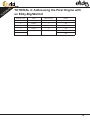
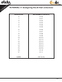
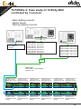
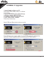


![取扱説明書[SR-PX3/PA3] (13.72 MB/PDF)](http://vs1.manualzilla.com/store/data/006676924_3-b973de39c9e5b62b81cd202f0ed8d8fe-150x150.png)