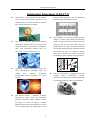
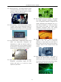
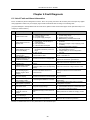
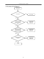
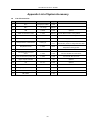
1
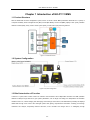
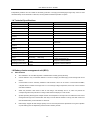
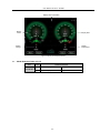
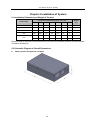
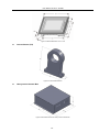
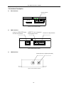
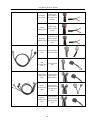
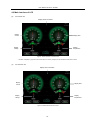
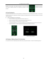
User Manual of EK-FT-11 -1- User Manual of EK-FT-11 BMS Preface Thank you for selecting Ligoo EK-FT-11 electric vehicle BMS (BMS: Battery Management System). In order to install, use and maintain the product better, please read this user manual (hereinafter called “manual”) carefully before installation and use. EK-FT-11 is a new BMS developed by Ligoo for the developing demand of electric vehicles. Based on the demand features as strong interference, high voltage and high stability of large electric vehicle, EK-FT-11 is designed with strong applicability. The product is selected and configured according to different components, which can meet various application demands of customer and provide outstanding product performance. EK-FT-11 can well shield the strong electromagnetic interference of electric vehicles through effective isolation and design mode and improves the safety, stability and reliability by virtue of automotive-class processor chip, CAN bus communication and hardware and software designed with high redundancy. 1.1 Prompt This manual includes important information that must be mastered by customers. Our company will not undertake any related consequence or liabilities if customer doesn’t install, use and maintain the product in strict accordance with this manual. 1.2 Enterprise Qualification and Related Certification CE Certification Six Patents Six Software Copyrights 1.3 Declaration This manual has been reviewed and verified for accuracy. The guidance and description of EK-FT-11 BMS included in this manual are correct. However, the subsequent EK-FT-11 BMS and manual may alter due to technical improvement. -2- User Manual of EK-FT-11 Outstanding Advantages of EK-FT-11 High precision — adopt special Vmin-EKF algorithm through multiple protections, such as temperature (most accurate SOC evaluation algorithm in the monitoring and invalid balance and so on. worldwide); accuracy of SOC evaluation is more than 95%, which is leading in the worldwide. Strong reliability — innovative and optimized structure design; the system circuit adopts high-redundancy High accuracy — based on special D-Filter algorithm design and support two kinds of mode for charge and high-accuracy collection system, all collection errors discharge: CAN bus and high voltage relay; the of system parameter (such as single cell voltage) are reliable operation of system is ensured through EMC within test, high/low temperature aging, water/dust proofness 0.2%; temperature collecting error ±1℃ (-20℃~85℃), current collecting error ±1A. and vibration test and so on; adoption of multiple power isolation programs has significantly improved the reliability of system collection and communication. BMU Battery module 1 BU S 充电机 BMU BMU Battery module 3 CAN BUS CA N Battery module 2 BCU US NB CA CAN BU 电机控制 器 S D MO S BU BMU High safety — double isolated circuit, strong current 仪表 safety, electromagnetic compatibility design and multiple active protection technologies 整车控制器 Battery module n CAN bus communication — intelligently interact with (comprehensive safety management and control complete system). Instrument and charger through multiple isolated CAN vehicle controller/motor controller. bus to realize the effective sharing of all information. High effective balance — application of leading high-frequency switch circuit and temperature protection technology (battery intelligent balance technology) can control the balance of multiple batteries at the same time with total balance current of 1A and ensures stable and reliable balance circuit -3- User Manual of EK-FT-11 BMS Insulation monitoring — the insulation detection module can effectively detect the insulation status of electric vehicles to realize the real-time display of insulation fault class and ensure personal safety. Heat management with high resolution — the system has multiple temperature management strategies, such as temperature difference management and high/low temperature limit management and so on, Real-time display — communicate with upper computer and double management of cooling and heating, or display screen through RS485/CAN interface to which ensures that system can operate within realize the real-time display of information as voltage, comfortable temperature, SOC and fault and so on of battery pack. extreme events as battery self-ignition and so on. section and prevents High-capacity data storage — support data storage capacity Strong current control — design strong current control temperature of 8G; can record all performance unit parameters of power battery and fault events of independently to realize the effective isolation of battery pack for long time; users can import data into strong and weak current, avoid crosstalk and improve computer quickly for later analysis through USB the performance of anti-electromagnetic interference, interface. system and battery-string management ensuring the safe and reliable running of system. Remote management interface — the system is equipped with distance-wireless transmission unit (DTU) interface, which can be used to exchange data System POST — the system self tests its voltage, temperature, communication, display and with remote monitoring center: upload battery voltage, other SOC, temperature, fault state and other data. functions after power on to ensure the normal operation of system itself. -4- User Manual of EK-FT-11 BMS Typical Application of EK-FT-11 By virtue of strong expandability, EK-FT-11 has been established with the product line for five main series and ten types, from household electric car to electric bus and from hybrid vehicle to pure electric vehicle to meet various all-around demands of different customers. Electric vehicle BMS In electric vehicles, BMS is an important component of electric control system of complete vehicle, which communicates with complete vehicle controller, intelligent charger and instrument through CAN bus, realizing safe, reliable and effective management of battery system. The complete vehicle controller reads BMS data through CAN bus, controls motor through intelligent motor controller, displays data on instrument panel and communicates with intelligent charger through BMS to realize intelligent charging control. The BMS anti-interference performance is very important for hybrid and pure electric bus. The strong electromagnetic interference will influence the normal operation of BMS. In order to solve the problem fundamentally, EK-FT-11 BMS adopts the design of multiple electromagnetic compatibilities and isolations, which has effectively shielded the electromagnetic interference and maintained the normal operation of system. The automotive class processor chip, automotive class CAN bus and high redundancy circuit have improved the safety, stability and reliability of system remarkably. The typical electric vehicle BMS is mainly composed of one Battery cluster-management unit (BCU), several (5-10) battery monitoring units (BMC) and one insulation detection module (LDM). Technical Features: High level of insulation and voltage-withstand — the level of insulation and voltage-withstand of EK-FT-11 can reach to the super insulation specified in national standard (refer to section 6.2.3 in GB/T18384.3 中 6.2.3). The system is -5- User Manual of EK-FT-11 BMS equipped with insulation monitoring function, which can realize the real-time display of insulation status and effective protection of invalid insulation to ensure personal safety. Heat management with high resolution — the system has multiple temperature management strategies, such as temperature difference management and high/low temperature limit management and so on, and double management of cooling and heating, which ensures that system can operate within comfortable temperature section and prevents extreme events as battery self-ignition and so on. High flame retardant rating — all system key parts in EK-FT-11 can reach to or excess automotive class flame retardant rating UL-94-V0. High anti-vibration level — all EK-FT-11 systems will be tested according to the vibration test standard specified in national standard before leaving factory to ensure the anti-vibration performance of system effectively. Strong anti-interference — the model selection of all critical elements meets the model selection requirement of automotive class element; effective isolation and filtering have been done for input and output; the performance of anti-electromagnetic interference has reached to harsh level (level 4 specified in GB/T17626.4-1998). Distributed two-level management — EK-FT-11 system adopts distributed two-level management mode with combination of handy management and centralized management, which have divided the system function reasonably, greatly simplifying the complexity of interface and control and improving system reliability. Powerful balance management — EK-FT-11 can manage the electric balance of battery according to intelligent balance strategy, which has ensured the consistency of battery effectively; besides, the battery pack can work in the uniform temperature section through heat balance management to ensure the temperature consistency of battery. Abundant extension interface — EK-FT-11 externally supports multiple active output, passive output and multiple isolated CAN bus output, which meet the requirement of diversified management and can effectively realize the intelligent management of battery. Accurate collection and estimation — two core technologies of special high-precision collection technology D-Filter algorithm and SOC estimation technology Joint EKF algorithm which is the most accurate in filed at present have effectively ensured EK-FT-11 industrial leading position in information collection and SOC estimation, guaranteeing the safety and mileage range of electric vehicle. Remote management interface — EK-FT-11 system is equipped with distance-wireless transmission unit (DTU) interface, which can be used to exchange data with remote monitoring center: upload battery voltage, SOC, temperature, fault state and other data. High-capacity data storage — support data storage capacity of 8G; can record all performance parameters of power battery and dispatching events of battery pack for long time; users can import data into computer quickly for later analysis through USB interface. Rapid upgrade of system — EK-FT-11 series BMS program downloading interface is installed externally, which can be used to upgrade system within 30 seconds. Management of operation authority — BMS system can set and modify battery operation protection parameters and alarm constant value and so on through touch screen and has the encryption management of operation authority. Any operation which changes system parameters needs authority confirmation. -6- User Manual of EK-FT-11 BMS Safety Guidelines Description of Safety Signs: Dangerous: dangers caused by operation not compliance with requirement may result to fire hazard, serious personal injury and even death. Caution: dangers caused by operation not compliance with requirement may result to moderate or minor personal injuries and system damages. Please read this section carefully when installing, using and maintaining this system and operate according to safety precautions required in this section. Any damage and loss caused by illegal operation have nothing to do with our company. Dangerous Application This series BMS must be powered by defined voltage. Otherwise, system may be damaged. This series BMS is only applied for information monitoring and management of battery pack and cannot be used for other purposes. Otherwise, system fault or fire hazard may be caused. Caution Incoming inspection System damaged or lack of components cannot be installed. Otherwise, accident may be caused. If there is difference between packing list and name of material object, please don’t install the system and contact with our company in time (see appendix A of this manual). Caution Please handle with care at the time of loading and installation to prevent dropping on foot or product from being damaged. Installation This system must be kept away from combustible objects and heat source. Don’t let foreign matters drop into system at the time of installation. Otherwise, system fault may be caused. The shell of insulation detection module must be well conducting with vehicle body. Otherwise, the insulation detection module may be invalid. Dangerous The wiring work must be done by qualified operator of electric engineering. Otherwise, electric shock or system damaged may be caused. The power supply must be disconnected before wiring. Otherwise, electric shock or fire hazard may be caused. Caution The installation must be carried out in strict accordance with serial number of Battery monitor unit address. Otherwise, the collected data may not be consistent with display on control platform. Wiring Check whether the battery quantity is same to that of Battery monitor unit. Otherwise, the collected data may be incomplete. Check whether the connection order of voltage detection wiring harness is correct. Otherwise, the system may be damaged. Check whether the wiring of control relay is correct. Otherwise, system and battery pack may be damaged. Check whether positive and negative poles wiring of power supply are correct. Otherwise, system may be damaged. Dangerous Operation -7- User Manual of EK-FT-11 BMS Power on only after all modules and display screen are connected correctly. The plug wire cannot be unplugged when the power is on. Otherwise, electric shock may be caused. Parameters of setting page cannot be altered at will. Otherwise, battery may be damaged. Caution Before operation, check whether the system is within allowed range of application. Otherwise, system may be damaged. Before operation, check whether the control strategy of system is right. Otherwise, battery may be damaged. Dangerous Maintenance check The power supply must be disconnected if it is necessary to disassemble the shell. Otherwise, electric shock may be caused. and The circuit board includes a large number of high-accuracy elements. Therefore, don’t touch it with hand to prevent the board from being damaged by static electricity. Please designate qualified operators of electric engineering to maintain, check or replace components. Dangerous Others Self modification for the system is prohibited. Otherwise, serious accident may be caused. -8- User Manual of EK-FT-11 BMS Contents Chapter 1 Introduction of EK-FT-11 BMS ................................................................................................ 11 1.1 Product Structure....................................................................................................................... 11 1.2 System Configuration ................................................................................................................ 11 1.3 Brief Introduction of Function..................................................................................................... 11 1.4 Technical Specifications............................................................................................................. 12 1.6 Battery cluster-management unit (BCU) .................................................................................... 12 1.7 Battery monitor unit (BMU) ........................................................................................................ 13 1.8 Insulation Detection Module (LDM) ........................................................................................... 14 1.9 Heavy-current Control System (HCS) ....................................................................................... 15 1.10 Current Sensor (CS) ................................................................................................................ 15 1.11 Display Screen (LCD) .............................................................................................................. 16 Chapter 2 Installation of System ..............................................................................................................18 2.1 Installation Dimension and Weight of Product ........................................................................... 18 2.2 Schematic Diagram of Overall Dimensions ............................................................................... 18 2.3 Interface Description ................................................................................................................. 22 2.4 Wiring Diagram of System ......................................................................................................... 24 2.5 Wiring Description of BMU ........................................................................................................ 25 2.6 Wiring Description of BCU ......................................................................................................... 27 2.7 Wiring Description of LDM ......................................................................................................... 29 2.8 Wiring Description of LCD ......................................................................................................... 29 2.9 Connect Communication Cables between LCD and BCU ......................................................... 30 2.10 Installation Conditions and Requirements ............................................................................... 30 Chapter 3 Wiring of System .....................................................................................................................31 3.1 Type of Cable ............................................................................................................................ 31 3.2 Diagram of Cables ..................................................................................................................... 32 3.3 Cable Quantity........................................................................................................................... 35 Chapter 4 LCD Application and Parameter Setting ..................................................................................36 4.1 Explanation of Parameters ........................................................................................................ 36 4.2 Main Interface of LCD ............................................................................................................... 37 4.3 User Permission ........................................................................................................................ 38 4.4 Display of Battery Single Cell Information ................................................................................. 38 4.5 Display of Charger Information .................................................................................................. 39 4.6 Display of Battery Statistical Information ................................................................................... 40 4.7 Configuration Interface .............................................................................................................. 40 Chapter 5 Application of Upper Computer Software ................................................................................42 -9- User Manual of EK-FT-11 BMS 5.1 Function of Upper Computer Software ...................................................................................... 43 5.2 Software Installation .................................................................................................................. 43 5.3 Application of BMU Upper Computer ......................................................................................... 43 5.4 LDM Upper Computer ............................................................................................................... 47 Chapter 6 Fault Diagnosis .......................................................................................................................49 6.1 List of Fault and Alarm Information ............................................................................................ 49 6.2 Procedure of Fault Diagnosis .................................................................................................... 50 Chapter 7 Daily Maintenance ..................................................................................................................51 Chapter 8 Service Guide .........................................................................................................................52 8.1 Contact Way .............................................................................................................................. 52 Appendix List of System Accessory .........................................................................................................53 -10- User Manual of EK-FT-11 BMS Chapter 1 Introduction of EK-FT-11 BMS 1.1 Product Structure With the distributed two-level management system, EK-FT-11 electric vehicle BMS (hereinafter called EK-FT-11 system) is composed of Battery cluster-management unit (BCU) and multiple Battery monitor unit (BMU), display screen (LCD), insulation detection module (LDM), heavy-current control system (HCS), current sensor (CS) and wiring harness. Figure 1-1 Product Structure 1.2 System Configuration Figure 1-2 System Configuration 1.3 Brief Introduction of Function In EK-FT-11 system, BCU module carries out real-time communications with multiple BMU modules and LDM (insulation detection module) through CAN bus to gain system parameters, such as single cell voltage, box temperature and insulation resistance and so on, collects charging and discharging current through current sensor, calculates SOC dynamically and displays related data through touch screen. BCU manages system after gaining comprehensive information of battery pack through calculation and analysis, respectively interacts with ECU, motor controller and charger and so on intelligently through -11- User Manual of EK-FT-11 BMS independently CAN bus and can realize the secondary protection of charging and discharging through relay control to meet diversified safety control demands of customers, ensuring stable and effective operation of system. 1.4 Technical Specifications Type Specification Voltage collection range 0~5V Voltage collection accuracy ±5mV Accuracy of total voltage 0.1% Current collection accuracy ±1% Error of SOC estimation ≤5% Temperature accuracy Temperature range collection collection Balance current Power consumption of BMU operation Power consumption of BCU operation -40~125℃ 300mA 3 channels of balance can be switched on at the same time 0.5W One BMU module ≤2.8W 3W Working input voltage DC 12/24V Storage temperature -45~125℃ Weight BCU:480g Discharging control mode 500A current sensor ±1℃ 3.5'' display screen Charging control mode Remarks Power consumption of sleep mode: 0.24W Weight of one Battery monitor unit and one Battery cluster-management unit BMU:640g CAN communication, output CAN communication, output active/passive active/passive Depend on actual conditions Depend on actual conditions 1.6 Battery cluster-management unit (BCU) BCU function SOC estimation: use Joint EKF algorithm to estimate SOC of battery pack dynamically Current detection: carry out real-time detection of current in charging and discharging circuits through Hall current sensor. Communication function: externally installed 3 CAN interfaces, which can be used to communicate with BMU, complete vehicle controller and charger and so on to exchange voltage, temperature, fault code, control command and other information. Alarm and protection: when there is fault as over-charge, over-discharge and so on, BCU can perform the corresponding alarm and protection according to fault status and display it on LCD screen. System expanding: BCU supports multiple channels of active/passive node output and can realize two-level control management through CAN communication and relay to ensure effective isolation of strong and weak current and meet diversified safety control demands of customers. Data storage: support 8G data storage capacity and can record all performance parameters of long-term operation of power battery pack and dispatching and fault events of battery module. -12- User Manual of EK-FT-11 BMS System self-check: the system checks itself and BMU working status after power on to ensure normal working of system. Remote management: BCU is equipped with wireless communication interface, which can realize four-remote function through external DTU module. System upgrade: program downloading interface is installed externally, which can be used to upgrade system within 30 seconds. Parameters of BCU module Item Performance Working voltage DC 12V/24V Current detection range Current detection accuracy Error of SOC estimation Display Alarm Charging control mode Discharging control ±500A (optional) ±1% ≤5% Total voltage, total current, maximum and minimum voltages and serial numbers, voltage of single battery, box temperature, charging and discharging status, over-charge alarm prompt, under-charge alarm prompt, over-discharge alarm prompt, over-temperature alarm prompt and insulativity alarm prompt, etc. Grade I alarm: prompted alarm information appears on display screen and no control measures are taken: Single cell voltage ≤3.0V; 100Ω/V≤ insulativity ≤500Ω/V Grade II alarm: prompted alarm information appears on display screen and there is bumming; disconnect charging and discharging circuits: Single cell voltage ≤2.5V or single cell voltage ≥3.9V; delay: 5-30S; Box temperature ≥75℃; Insulativity ≤100Ω/V Use CAN bus and relay to control: When the cell voltage of single battery ≥3.65V, carry out CAN communication with charger and the current value gradually decreases according to smooth curve. When the cell voltage of single battery ≥3.9V, disconnect charger output after 30S delay. When the cell voltage of single battery <3.4V, charger can be used again for continue charging. When the box temperature ≥75℃, charger is abnormal or charging circuit is disconnected. Use CAN and high-voltage relay to control the over-discharge of battery: If carrying with CAN communication, when cell voltage of single battery ≤3.0V, reduce motor output power; When the cell voltage of single battery ≤2.5V, disconnect motor power output after 5~10S delay. When battery box temperature ≥75℃, disconnect discharging circuit. Note: *all protection parameters in table can be configured. 1.7 Battery monitor unit (BMU) BMU function BMU connects with battery pack through voltage detection wire, collects voltage of 12 strings of battery cell at most and can equalize battery according to battery single cell voltage. When the voltage of some single cell battery in battery box reaches to 3.55V and battery voltage difference is between 20mv-800mv, the balance function will start automatically. Each battery detection unit can switch on 3 channels of balance at the same time at most. BMU collects box module temperature through 3 temperature sensors at most and can actively manage cooling and heating according to temperature status to ensure battery application capacity and prolong battery service life. The working power supply of BMU has to be provided by the external 12V (9V~18V self-adaption) or 24V (18V~36V self adaption) DC power source. BMU transmits the collected battery voltage, box temperature and other information to Battery -13- User Manual of EK-FT-11 BMS cluster-management unit through CAN bus. Detection of single cell voltage: realize the real-time detection of each single cell voltage through isolated collection of series single cell voltage. Temperature detection: put 1~3 temperature sensors in box of battery module to realize the real-time detection of box temperature. CAN communication: transmit the voltage, box temperature and other information of each single cell in battery pack to BCU through CAN bus. Balance function: balance management can be performed to battery cell according to agreed balance management control strategy to improve the consistency of single battery cell and application performance of battery pack. Heat management: BMU can manage the cooling and heating status of battery actively according to battery box temperature to ensure battery application capacity and prolong battery service life. System upgrade: program downloading interface is installed externally, which can be used to upgrade system within 30 seconds. Parameters of BMU module Item Parameter Maximum quantity of collection string 12 strings Working voltage DC9V~36V Voltage collection range 0~5V Collection accuracy of single cell voltage Temperature collection range Temperature detection accuracy Remarks ±5mV -40~125℃ ±1℃ Communication interface CAN Voltage sampling period 200ms Power of cooling fan 12W 12S 1.8 Insulation Detection Module (LDM) LDM function LDM is used to detect whether the battery pack has electricity leakage on vehicle body. LDM receives the command from BCU through serial bus and transmits the detected data information to BCU, which then will deliver LDM status to display screen. Method to judge whether the battery leaks electricity onto vehicle body: respectively detect whether the insulativity between positive/negative pole of vehicle-mounted battery and body shell is more than 500Ω/V. Insulativity System Status Display Screen Insulativity ≥500Ω/V Normal system display Green displays on screen 100Ω/V≤ insulativity ≤500Ω/V System alarm I Yellow displays on screen; system doesn’t cut off circuit. Insulativity ≤100Ω/V System alarm II Red displays on screen; system cuts off circuit. -14- User Manual of EK-FT-11 BMS 1.9 Heavy-current Control System (HCS) Heavy-current control system includes heavy-current control module, charging and discharging control circuits and pre-charge circuit, etc. HCS function Charge and discharge control: charging/discharging of battery is controlled through switching on/off high-voltage relay to prevent over-charge and over-discharge of battery; besides, the function of relay contact detection is also equipped to prevent sticky point of relay in circuit. Pre-charge circuit: before switching on the discharging high-voltage relay of main circuit, it is necessary to switch on the pre-charge circuit firstly to charge capacitance. Then, switch on the high-voltage relay of main circuit when the voltage at both terminals of capacitance has reached to setting threshold value to ensure the reliability of high-voltage relay of main circuit. CAN and RS485 communication: use CAN or RS485 bus to communicate with BCU, upload relay status and other information and receive the control command from BCU. Table of Relay Model Selection Item Code Detailed Parameters 01 EV200AAANA 02 400V/10A Relay Model 03 400V/80A 04 400V/120A Model Selection Table of Power and Resistance of Heavy-current Module Item Power Model Resistance Model Code Detailed Parameters 00 50W 01 75W 02 100W 04 300W 01 50Ω 02 75Ω 03 100Ω 07 240Ω 1.10 Current Sensor (CS) CS function The current of this system is detected with Hall open-loop current sensor with optional range 50A~1000A. Model Selection Table of CS -15- User Manual of EK-FT-11 BMS Item Code Detailed Parameters 01 50A 02 100A Current 04 200A Type 05 300A 07 500A 10 1000A 1.11 Display Screen (LCD) LDM function The display screen is human-machine interface for displaying system operation status. All its models are designed according to industrial standard and suitable for applying in various conditions. The display interface of LCD can display all operation parameters and faults of system. Status description of LCD The operation indicator of display screen includes three ones: power supply (PWR), running (RUN) and communication (COM). When the display screen is powered on, the power indicator (PWR) is normally on; if the running indicator (RUN) is normally on in yellow, it stands for normal running of display screen; if the running indicator (RUN) is not on, it means that the display screen has fault; when the display screen has connected with BMS, the communication indicator (COM) flashes in yellow. Figure 1-3 Running Status Indicator The following table shows the display status of three LED indicators under various conditions: Equipment Status Green LED (PWR) Yellow LED (RUN) Yellow LED (COM) No power supply ○ ○ ○ 3.5’’ screen ● ● ● 5.7’’ screen ● ● ○ ● ● ※ Power on, no communication Communicate with connected equipment ○ LED off ● LED on ※ Flash Display description of LCD The integrated interface information of display screen is as shown in the figure below: -16- User Manual of EK-FT-11 BMS Display alarm information Display current Display SOC Display voltage Display temperature Figure 1-4 Figure of LCD Display Interface Model Selection Table of LCD Item Code Detailed Parameters 01 Display screen 3.5’’ 02 Display screen 5.7’’ LCD Model -17- User Manual of EK-FT-11 BMS Chapter 2 Installation of System 2.1 Installation Dimension and Weight of Product Overall and Installation Dimensions (unit: mm) Weight Product Type d (KG) 50 M4 0.64 100 40 M4 0.48 25 105.5 85 15 4.5 1.05 240 100 130 225 26 6 — 96 81 47 90 75 5 4 0.186 177 140 40 160.6 130.5 6 4 0.5 W H D W1 H1 BCU 165 106 43 100 BMU 124 91 40 LDM 165 120.5 HCS 260 D1 LCD Note: W, H and D are dimensions of external structure; W1, H1 and D1 are installation dimensions of internal structure; d is width of mounting hole. 2.2 Schematic Diagram of Overall Dimensions Battery cluster-management unit (BCU) -18- User Manual of EK-FT-11 BMS Figure 2-1 BCU Overall Dimension Battery monitor unit (BMU) -19- User Manual of EK-FT-11 BMS Figure 2-2 BMU Dimension Insulation Detection Module (LDM) Figure 2-3 LDM Dimension Display Screen (LCD) -20- User Manual of EK-FT-11 BMS Figure 2-4 Overall Dimension of 5.7’’ LCD Current Sensor (CS) Figure 2-5 CS Overall Dimension Heavy-current Control Box Figure 2-6 Overall Dimension of Heavy-current Control Box -21- User Manual of EK-FT-11 BMS 2.3 Interface Description BCU interface Internal interface 对内接口 SD card 1 11 13 27 2 12 14 28 Figure 2-7 Front Interface of BCU BMU interface Interface for system power supply 系统电源和 Interface for heat management 热管理和 and CAN communication CAN通讯接口 and temperature sensor 温感接口 Interface for voltage detection 电压检测接口 1 11 1 11 13 27 2 12 2 12 14 28 Figure 2-8 Back Interface of BCU LDM interface Positive pole (red) Negative pole (black) 正极(红色) 负极(黑色) Figure 2-9 Front Interface of LDM -22- User Manual of EK-FT-11 BMS RS485 communication interface RS485 communication interface RS485 通讯接口 RS485 通讯接口 Figure 2-10 Back Interface of LDM 5.7’’ LDC interface USB interface 12V voltage input interface COM1 interface COM2 interface Figure 2-11 5.7'' LCD Interface CS interface Interface for current sensor Figure 2-12 CS Interface -23- User Manual of EK-FT-11 BMS 2.4 Wiring Diagram of System Figure 2-13 Schematic Diagram of Installation -24- User Manual of EK-FT-11 BMS Note: * products of different models may have some difference in functions and settings. The installation method of special connecting lines and adaptors will be provided by our company separately. 2.5 Wiring Description of BMU Connection of voltage detection wiring harness (take 12 strings for example) B1+ connects with positive pole (red line) of first battery; B1-~B11- connect with negative pole (black line) of each battery in series successively; B12- connects with negative pole (green line) of the last battery. Positive pole of battery module Negative pole of battery module Figure 2-14 Schematic Diagram of Connection between Voltage Detection Wiring Harness and Battery Figure 2-15 Example Diagram of Connection between Voltage Detection Wiring Harness and Battery Caution: the connection order of voltage detection wiring harness cannot be wrong. Otherwise, the voltage collection may be incorrect, equalizing circuit may be burnt out and battery may be damaged. Fix temperature sensor onto battery pack -25- User Manual of EK-FT-11 BMS Figure 2-16 Example Diagram of Temperature Sensor Connection Connect voltage detection cable harness and temperature detection cable to BMU Figure 2-15 Example Diagram for Connection of Voltage Detection Cable Harness and Temperature Detection Cable Connection of CAN Communication Cable CAN communication cable is the communication medium between BMU and BCM. The system adopts 3-core shielding line to be communication cable. MOLEX12pin connector assembly and AMP 6PIN automobile connector (cellular type and pin type) are used for joint. The example diagram and schematic diagram of connection are as follows respectively: Figure 2-18 Schematic Diagram for Connection of Serial Communication Bus - -26- User Manual of EK-FT-11 BMS The BMU farthest away from BCU connects to No. 2 line and others connect to No. 1 line. Figure 2-19 Example Diagram for Connection of Communication cables among BMUs 2.6 Wiring Description of BCU Connect communication cable s between BCU and BMU Figure Diagram for Connection of Communication cable s between BCU and BMU Connect current sensor The current sensor is strung onto the circuit cable of output positive/negative pole of battery pack and has two kinds of wiring modes, as shown in the figure below (pay attention to the arrow on current sensor). Connection method 1 Connection method 2 Figure 2-21 Schematic Diagram for Connection of Current Sensor Installation -27- User Manual of EK-FT-11 BMS Figure 2-22 Example Diagram for Connection of Current Sensor Connect the control cable of charge/discharge relay (red line connects with positive pole of relay coil and black one with negative pole of relay coil). Figure 2-23 Example Diagram for Connection of Relay Control Cable Connect CAN communication cables of charger and complete vehicle system/motor controller. (For 3-core shielding line: red is H, yellow is L and black is GND) Figure 2-24 Example Diagram for Connection of CAN Communication Cable Caution: 1. Confirm that the connection of “H” and “L” of CAN bus is correct. Otherwise, CAN bus cannot communicate with other devices. 2. Confirm that the matched resistance of CAN bus is correct. Otherwise, CAN bus cannot communicate with other devices. -28- User Manual of EK-FT-11 BMS Connect the power supply cord of BCU (red line connects with positive pole of power supply and black one with negative pole). Figure 2- 25 Example Diagram for Connection of BCU Power Cord 2.7 Wiring Description of LDM Connect communication cables between LDM and BCU; connect LDM to the master positive pole and master negative pole of battery pack; and make LDM shell contact with vehicle body and keep well conducting between them (LDM shell grounded). Figure 2-26 Example Diagram for Connection of Communication Cables between LDM and BCU Caution: LDM shell must well contact with vehicle body. Otherwise, functions of LDM will be invalid! Dangerous: it is necessary to wear insulation gloves when connecting positive/negative pole wire of detection. Otherwise, electric shock may be caused! 2.8 Wiring Description of LCD Wiring description of display screen (take 5.7’’ one for example) Both interfaces for power supply and communication of display screen of this system have to connect with BCU. The schematic diagram of connection is as follows. -29- User Manual of EK-FT-11 BMS USB-B 24VDC - + COM2 COM1 USB-A Power interface of control panel, Communication interface of control panel, connect with power interface of BCU connect with data bus interface of BCU console (LCD PWR) 电源接口(LCD PWR) console (LCD BUS) BUS) 数据总线接口(LCD 控制台通讯接口,接CCM控制台 控制台电源接口,接CCM控制台 Figure 2-27 Wiring of 5.7'' Display Screen 2.9 Connect Communication Cables between LCD and BCU Figure 2-28 Example Diagram of Communication Cables between LCD and BCU Caution: 1. the communication cable interface (DB9 connector) of LCD connects to COM1 communication interface of LCD. If it is connected to COM2 interface, the LCD communication will be interrupted! 2. The connection of positive and negative poles of LCD power cannot be reversed. Otherwise, LCD will be burnt out! 3. LCD is powered by DC24V. The positive pole connects with 24V+ and negative one with 24V-! 2.10 Installation Conditions and Requirements Avoid installing the system under the condition with oil mist, metallic dust and much dust. Avoid installing the system under the condition with harmful gas and fluid or corrosive, flammable and explosive gas. Reserve appropriate installation dimensions. Cable installation shall be kept away from sharp objects. Try best to keep away from conditions with strong electromagnetic interference. Parameters of all parts related to connection with this system shall be confirmed by our company. -30- User Manual of EK-FT-11 BMS Chapter 3 Wiring of System 3.1 Type of Cable No. 1 2 Name Specification Voltage detection cable 0.5 high temperature wire: one end is MOLEX28PIN connector assembly; the other end is 1.5-8 cold pressed terminal. Temperature detection cable 2×0.5 high temperature wire: one end is MOLEX28PIN connector assembly; the other end is temperature sensor. Fan power cord 2×0.5 power cord: one end is MOLEX28PIN connector assembly; the other end is null. Communication cable among modules Power cord Master-slave power cord 3 3×0.5 shielding line and 2*1.0 high temperature wire: one end is MOLEX12PIN connector assembly; Communication among the other end is 6PINAMP connector assembly (cellular type BMUs, and power cord and pin type). 2×0.5 power cord: one end is MOLEX12PIN connector assembly; the other end is null. 2×0.5 power cord: one end is MOLEX12PIN connector assembly; the other end is 6PIN AMP connector assembly (cellular type). Discharge relay cable 2×0.5 power cord: one end is MOLEX12PIN connector assembly; the other end is null. Input signal cable 2×0.5 power cord: one end is MOLEX12PIN connector assembly; the other end is null. Discharge CAN cable 3*0.5 shielding line: one end is MOLEX20PIN connector assembly; the other end is null. Charge CAN cable 3*0.5 shielding line: one end is MOLEX20PIN connector assembly; the other end is null. Charge relay cable 2×0.5 power cord: one end is MOLEX20PIN connector assembly; the other end is null. Pre-charge relay cable 2×0.5 power cord: one end is MOLEX20PIN connector assembly; the other end is null. 4 2×0.5 power cord: Charge switching signal one end is MOLEX20PIN connector assembly; cable the other end is null. 5 Remarks Size of cold pressed terminal is determined according to the actual demand of customer. Discharge switching signal cable 2×0.5 power cord: one end is MOLEX20PIN connector assembly; the other end is null. Connecting wire of current sensor 4×0.5 shielding line: one end is MOLEX8PIN connector assembly; -31- Share the same one 6PIN AMP connector assembly with master-slave communication cable User Manual of EK-FT-11 BMS the other end is 5569 (2×2) cellular terminal. 6 USB communication cable 4×0.5 shielding line: one end is MOLEX8PIN connector assembly; the other end is USB interface. Master-slave communication cable 3×0.5 shielding line and 2*1.0 high temperature wire: one end is MOLEX28PIN connector assembly; the other end is AMP6PIN cellular connector assembly. Screen communication cable 5×0.3 shielding line: one end is MOLEX28PIN connector assembly; the other end is DB9 terminal (cellular) and 2PIN plug. LDM communication cable Share the same one 6PIN AMP connector assembly with master-slave power cord 3×0.5 shielding line and 2*0.5 power cord: one end is MOLEX28PIN connector assembly; the other end is AMP6PIN pin-type connector assembly. Note: *1. the cable length is determined through consultation between customer and our company. *2. The type of charge and discharge cables is determined according to requirement of customers. *3. For wiring mode, please refer to instructions for system installation. *4. If special cables are needed, please contact technical support center of our company. 3.2 Diagram of Cables Following pictures show common cables produced by our company. Diagram Name Application Temperature temperature detection cable information of Detect battery Fan control Connect with fan cable on battery box Connect with Voltage detection cable battery and BMU, detect voltage -32- Interface User Manual of EK-FT-11 BMS Communication Communication cable among among all BMUs, modules and power cord Power cord (red “+”, black Supply power for BCU "-") Master-slave Supply power for power cord BMU Connect with Discharge relay control cables of cable discharge relay and BCU Input signal Input level signal cable for BCU Complete vehicle CAN cable Connect with motor controller/complete vehicle controller Charge CAN Connect with cable charger Charge relay control cables of cable charge relay and Connect with BCU -33- User Manual of EK-FT-11 BMS Connect with Pre-charge control cables of relay cable pre-charge relay and BCU Output charge Charge switching cable switching signal to charger Output discharge Discharge switching signal to switching cable motor controller or others Current sensor Connect with BCU cable and current sensor USB communication Download saved data cable Master-slave Communication communication cables between cable BMU and BCU Communication Screen communication cable LCD, and power cord Communication Insulation communication cable between BCU and between BCU and LDM, and power cord -34- User Manual of EK-FT-11 BMS 3.3 Cable Quantity In the following table, a set of EK-FT-11 system is taken for example to explain cable quantity required by product. One of products takes one BCU and N (≤22) BMUs for example to explain the quantity of each cable, as shown in the table below. Name Qty. Unit Voltage detection cable N Set Remarks Quantity of each set of voltage detect cable is equal to that of determined BUM. Temperature detection N Set There are 3 temperature sensors on each set of cable. M Set Optional N PCS Communication cables among BMUs 1 PCS cable Fan power cord Communication cable among modules Each BCU, BMU and LDM corresponds to one power cord Power cord respectively. Master-slave power cord 1 PCS 1 PCS 1 PCS 1 Set Discharge switching cable 1 PCS Discharge CAN cable 1 PCS Discharge relay cable 1 PCS Charge relay cable 1 PCS Charge CAN cable 1 PCS Charge switching cable 1 PCS Pre-charge relay cable 1 PCS Optional USB communication cable 1 PCS Optional Input signal cable 1 PCS Optional 1 PCS Optional Master-slave communication cable Connecting wire of current sensor Screen communication cable The corresponding discharge mode and harness corresponding to one cable are selected by customers. The corresponding charge mode and harness corresponding to one cable are selected by customers. Insulation communication cable -35- User Manual of EK-FT-11 BMS Chapter 4 LCD Application and Parameter Setting 4.1 Explanation of Parameters Total capacity Capacity of battery pack after being fully charged; Usually, it is initially configured to nominal capacity of battery pack. Surplus capacity Maximum Currently surplus ampere-hours of battery pack; it is set according to parameters provided by battery manufacturer. Set maximum allowed charging voltage of charger through CAN communication. charging voltage Maximum charging current Set maximum allowed charging current of charger through CAN communication. Over-charge Set the maximum voltage threshold value that single cell battery can raise during protection charging. Carry out over-charge protection to battery and alarm when it is more than voltage this value. Over-charge Set to cancel the voltage threshold value of overcharge protection, i.e. to cancel protection over-charge protection and alarm when the maximum voltage of single cell battery release drops to the value lower than threshold value. Under-voltage Set threshold value of alarm for low voltage of battery single cell, which is used to alarm voltage prompt low power of battery. Under-voltage alarm release Set to cancel the voltage threshold value of under-voltage alarm, i.e. to cancel under-voltage alarm when the minimum voltage of single cell battery recovers to the value more than this parameter. Over-discharge Set the minimum voltage threshold that battery can drop to during discharging. protection Carry out over-discharge protection to battery when the voltage is lower than the voltage value. Over-discharge Set to cancel the parameter of battery over-discharge protection, i.e. to cancel protection battery over-discharge protection when the minimum voltage of single cell battery release recovers to the value more than this parameter. Over-temperature Set allowed maximum operating temperature of battery pack. Carry out battery protection over-temperature protection and alarm when the temperature is higher than the temperature value. Over-temperature Set the temperature threshold of over-temperature alarm release, i.e. to cancel protection over-temperature protection and alarm when the maximum temperature of battery release drops to the value lower than the threshold. -36- User Manual of EK-FT-11 BMS 4.2 Main Interface of LCD (1) For terminal user Display alarm information Display current Display SOC Display voltage Display temperature Figure 4-1 Main Interface of Terminal User Remarks: It displays in gray when alarm information is normal; it displays in red and flashes when there is alarm. (2) For advanced user Display alarm information Display current Display SOC Display voltage Display temperature Figure 4-2 Main Interface of Senior User -37- User Manual of EK-FT-11 BMS Remarks: at this moment, click “battery information” to pop up the window Compared with terminal user interface, statistical information and configuration information are newly increased in senior user interface. 4.3 User Permission The touch screen has the function to set user permission. The terminal user can only browse general information. For senior user, statistical information and configuration information of battery are increased. When the touch screen is powered on, the default user is terminal user. Steps for modification of user permission Step 1: click “Menu” to pop up the window as shown in figure 4.3.1. Step 2: click “User Information” to pop up the window as shown in figure 4.3.2. Step 3: click “Modify” and enter password to change user name. If the entered password is 1111, the user is terminal user. If the entered password is 5555, the user is senior user. Step 4: click "Return". The main interface can alter automatically according to user name. Figure 4-3 Menu Figure 4-4 User Information 4.4 Display of Battery Single Cell Information The system will enter the corresponding interface after clicking “Single Cell Information”, as shown in the following figure 4-5. -38- User Manual of EK-FT-11 BMS Voltage value of module 1 Temperature value of module 1 Page up Page down Voltage value of module 2 Temperature value of module 2 Figure 4-5 Single Cell Information Remarks: above figure gives the corresponding information of modules 1 and 2. Each module includes the information of 16 single cell voltages and 3 module temperatures. 4.5 Display of Charger Information The system enters into corresponding charger interface after clicking “Charger”. Figure 4-6 Charger Information Remarks: the interface displays some information of charger. Receive the corresponding messages of charger through CAN communication and display them on the touch screen. -39- User Manual of EK-FT-11 BMS Explanation of parameters Online status: communication status of charger; it displays online when charger is communicating with BMS; otherwise, it is offline; the default status is offline. Starting status: indicate whether the charger has started to charge; it indicates starting after starting to charge; otherwise, it is stopping; the default status is normal. Hardware fault: malfunction of charger itself, default to normal. Input voltage: indicate the status of charger input voltage, default to normal. Temperature status: indicate the temperature status of charger, default to normal. Output current: indicate present charging current of charger. Output current: indicate present charging voltage of charger. 4.6 Display of Battery Statistical Information The information is mainly used for analysis of battery performance and application status. Step 1: change user information to senior user. Step 2: click “Battery Information”. Step 3: click “Statistical Information”. Figure 4-7 Statistical Information 4.7 Configuration Interface In order to evaluate all parameters of battery accurately, it is necessary to re-configure BMS before its initial running. The configurable content includes: total capacity of battery pack (nominal capacity), current surplus capacity of battery pack, maximum charging voltage, maximum charging current, over-charge voltage of single cell battery, over-charge release voltage of single cell battery, under-voltage protection voltage of single cell battery, under-voltage release voltage of single cell battery, -40- User Manual of EK-FT-11 BMS over-discharge protection voltage of single cell battery, over-discharge release voltage of single cell battery, over-temperature protection temperature and over-temperature release temperature. Steps of parameter configuration: Step 1: change user information to senior user. Step 2: click “Configure Information” of main interface. The system displays a configuration interface as shown in figure 4.7.1. Step 3: click “Read” to read the default configuration parameters of host. The system doesn’t support automatic reading of configuration parameter. Therefore, it is required to click "Read" after entering the configuration interface. Step 4: click the corresponding parameter column to modify the corresponding parameter. Step 5: Click “Write in” to enter the password 8888. Configuration parameters are related to the running status of system. Therefore, they cannot be altered at will. After clicking, if you didn’t operate step 3 previously, the dialog box for reading will pop up. If you have operated step 3, system will pop up a dialog box for write-in confirmation. The configuration parameter can be read before writing in. Step 6: When writing into the dialog box, click "Write in" and wait for 5 seconds around. It means that the setting operation has been finished when the COM indicator light flashes normally. If the indicator displays abnormally, you can click “Write in” again and then click “Return”. Return to main menu Read configuration information from BMS Recover configuration information to factory value Write configuration information into BMS Figure 4-8 Configuration Information Remarks: the relationship between configuration parameters is as follows: 1. over-charge voltage > over-charge release > under-voltage release > under-voltage voltage > over-discharge release > over-discharge protection 2. Over-temperature release < over-temperature protection 3. Surplus capacity < total capacity Recover configuration parameters to default value: Step 1: click the button “Restore Default”. The dialog box to inquire whether confirm the restoration pops up. -41- User Manual of EK-FT-11 BMS Click “OK” in the popped-up dialog box. Then, the configuration information restores to default value. Step 2: Step 3: click "Write in" to write default value into BMS. Chapter 5 Application of Upper Computer Software -42- User Manual of EK-FT-11 BMS 5.1 Function of Upper Computer Software Communicate with BMU, BCU, memory module and LDM. Analyze the data information transmitted by all modules and then display voltage, temperature and configuration value and so on. Configure information for each module through upper computer. Can request data automatically. 5.2 Software Installation System requirement: all systems above Win98. Software running: operate .EXE file directly. 5.3 Application of BMU Upper Computer BMU can be tested and configured independently through using upper computer software. 1. Main interface of configuration Figure 5-1 Main Interface of M1112 Slave Parameter Configuration The default configuration parameter of “Slave Configuration” is as shown in the table below: 1 Slave address Configure according to actual situation. Range: 1~255 2 Battery quantity Configure according to actual situation. Range: 1~12 strings 3 Voltage calibration value Configure according to actual situation. Range: 5000~5000mV 4 Over-temperature threshold Protection value: 60℃ 5 Over-charge voltage 6 Over-discharge voltage 7 Heating control Release value: 40℃ Protection value: 3850mV Release value: 3400mV Protection value: 2600mV Release value: 2800mV Opening temperature: configure according to actual situation Closing temperature: configure according to actual situation -43- User Manual of EK-FT-11 BMS 8 Historical data 9 Under-voltage threshold 10 Fan control Maximum temperature: factory configuration is 25℃. Minimum temperature: factory configuration is 25℃. Protection value: 2900mV Release value: 3000mV Opening temperature: 60℃ Closing temperature: 40℃ Number of balance channels: 2 Opening voltage: 3550mV 11 Battery balance Opening differential voltage: 40mV Over-temperature threshold: 60℃ Maximum differential voltage of energy forbidden: 800mV Figure 5-2 Display Interface 3 of Upper Computer Configuration 2. Parameter configuration method Run upper computer software. Enter interface 1 of dialog box for upper computer connection and connect USB-CAN converter. Figure 5-3 Interface 1 of Dialog Box for Upper Computer Connection Click “Connect (C)” to enter interface 2 of dialog box for device connection (figure 5-4). Select the corresponding device number, channel number and baud rate. Then, click “Connect (O)”. -44- User Manual of EK-FT-11 BMS Figure 5-4 Interface 2 of Dialog Box for Upper Computer Device Connection After entering the interface 3 of dialog box for upper computer connection, select "Separate-Slave (S)" to enter the display interface 1 of BMS upper computer configuration (figure 5-5). Figure 5-5 Interface 3 of Dialog Box for Upper Computer Connection Figure 5-6 Display Interface 1 of Upper Computer Configuration Parameter configuration -45- User Manual of EK-FT-11 BMS Click “Parameter Setting” to enter the dialog box of parameter setting. Select the option “Slave Configuration”. Then, click the button "Load Parameter (L)" to import parameter configuration files or manually fill in data to be configured and select the front check box. Finally, click “Setting (S)”. Figure 5-7 Display Interface of Parameter Setting You can also click the button "Read Parameter (G)" to gain all configuration parameters of slave and modify them as required. When configuring the slave in batches, you can click “Save Parameter (A)” to generate the similar configuration files as “Slave _03_2011_09_01_02_44.lgpara”. Hereafter, you only need to re-load. After finishing the configuration, you can click “Read Parameter (G)” or return to “Slave Parameter”. Then, click “Read (R)” to check the configured slave data. Click “Esc (E)” to return to main interface after the completion of configuration. Click "Gain (G)" to obtain all data of slave. Select the check box "Automatically Gain" and set the interval time. Then, click "Gain (G)" again to obtain slave information periodically. -46- User Manual of EK-FT-11 BMS Figure 5-8 Display Interface 2 of Upper Computer Configuration 5.4 LDM Upper Computer LCD can be detected independently through using upper computer software. The detection step is as follows: Step 1: connect the positive pole and negative pole of LDM to the master positive pole and master negative pole of battery respectively. Step 2: connect LDM with PC through USB/RS485 adaptor. Step 3: supply power for LDM with DC12V or DC24V. Step 4: open upper computer software ( initialization setting as shown in figure 5-9), "Port" is “COM1” (freely configure according to upper computer interface), “Baud Rate” is “9600”, “Check Bit” is “None”, “Data Bit” is “8”, “Stop Bit” is “1”. Then, click the “Open Serial Port” in the interface. Figure 5-9 Initialization Setting Step 5: after connection of power cord, click the button "Check" (parameter check as shown in figure 5-10) in the interface to read display value. Figure 5-10 Parameter Check Normal detection conditions of insulation monitoring: Insulation resistance of positive pole: >1MΩ. Insulation resistance of negative pole: >1MΩ. Total voltage: only values above 100V are valid. Fault code: 00 stands for normal working; 01 stands for offline status; 02 stands for electricity leakage. Working code: 00。 -47- User Manual of EK-FT-11 BMS -48- User Manual of EK-FT-11 BMS Chapter 6 Fault Diagnosis 6.1 List of Fault and Alarm Information EK-FT-11 BMS has perfect management functions, which can prolong the service life of battery. Some fault tips may appear during application. Please carry out analysis, judge causes and eliminate fault according to the following table. (If system damaged or meet problems that cannot be solved, please contact the technical support center (400-0551-306) of our company to obtain solutions.) No. Fault Description Possible Cause 1 System doesn’t work. 1. working voltage incorrect 2. no power supply 3. DC power supply damaged 2 Buzzer alarms and LCD displays fault. 1. Over-charge, over-discharge or under-voltage 2. over-temperature 3. communication interrupted 3 Buzzer alarms. But LCD has no fault display. 4 5 6 LCD displays error communication. LDC displays voltage=0 (multiple batteries or two consecutive batteries) The maximum temperature indicates -40℃. Solutions 1. Temperature difference at temperature detection point is too large. 2. SOC too low Incorrect connection of communication cable Incorrect connection of voltage cable Incorrect connection of temperature sensor Incorrect connection of voltage collection cable for the corresponding battery 7 Voltage display of partial batteries is abnormal. 8 Current displays positive when discharging and displays negative when charging. Incorrect installation direction of current sensor 9 No current display Incorrect connection of current sensor 10 There is current display when system is static. “Current digital calibration” is not set. 11 Current display is incorrect when system is operated. Incorrect matching of current sensor 12 LCD doesn’t work. No power supply voltage 13 14 15 Charging current < maximum current of charger Cannot protect over-charge or over-discharge SD card cannot write in. 1. Check whether the working voltage is within normal voltage range. 2. Supply power for system. 3. Maintained by professional technicist. 1. Check parameter setting of battery protection. 2. Disconnect charger or stop supplying power for battery. 3. Check communication interface. 1. Stop charging and discharging and restart after temperature recovery. 2. Charge battery or correct configuration manually. Check whether the power interface of LCD is loose or has fallen off. Check whether the voltage detection cable harness is connected in good stations. Check and reconnect temperature sensor. Check and reconnect voltage collection cable. Change the direction and re-install current sensor. Check whether the current sensor is connected in good stations. Refer to "explanation of configuration parameters". Check whether the current sensor is original configuration of system. 1. Check whether the host has supplied power. 2. Check whether the power cord between host and LCD is connected correctly. Maximum charging current is set too low. Reset parameter of maximum charging current. Incorrect parameter setting Reset parameter SD card write-in is protected. Switch off SD card write-in protection. Remark: for detailed fault icons of LCD, please refer to LCD introduction part. -49- User Manual of EK-FT-11 BMS 6.2 Procedure of Fault Diagnosis Start system NO Fault appears Use normally YES Troubleshoot according to 6.1 List of Fault and Alarm Information and check whether it is included in the table. NO Consult technical support center 400-0551-306. YES NO Find possible cause and solutions according to the table and check whether the system has recovered to normal after adjustment. Consult technical support center 400-0551-306. YES NO Fault reset, check whether the fault has been eliminated. Consult technical support center 400-0551-306. YES End -50- User Manual of EK-FT-11 BMS Chapter 7 Daily Maintenance Factors as service environment (such as temperature, humidity, dust and interference and so on), aging and abrasion of internal components and so on will increase the fault occurrence rate of system. It is necessary to carry out daily maintenance to decrease fault occurrence rate and prolong system service life. Caution: Only trained professional operators can disassemble and replace the internal components. It is necessary to switch off the power supply before checking and maintaining. Prevent metal or other matters being left in system. Otherwise, system may be short circuited and damaged Service environment In order to improve the function realization and prolong the service life of system, it is necessary to keep good installation environment. Generally, it is required to avoid direct high light for long time or other radiation and prevent water, other fluid, dust or dirt and so on from entering. BCU and BMU modules Check input voltage and input current with voltmeter and ampere meter to see whether they are within normal range. You can refer to description of system parameters. The output voltage and output current also can be checked with voltmeter and ampere meter to see whether they are within rated range. It is possible to perform intuitive judgment through touching, smelling and visual inspection to prevent these factors influencing its functions. LCD It is necessary to clean LCD frequently to keep it clean. Don’t crash or abrade it. Otherwise, the sight line will be interfered, which will cause incorrect judgment. Different components have different service life. The service life of components is influenced by environment and application conditions. Keeping good operating environment is good for the improvement of component service life. Wires of various plugs (e.g. air plug), PIN connector and serial port easily fall off from their welding spot, causing open circuit. Please replace them in time if there is any damage. It is necessary to cut off power supply before replacement. DC-DC is easily short circuited or damaged under high voltage. Please replace it in time if there is any damage. It is necessary to cut off power supply before replacement. Various wires are easily of short circuit or open circuit due to vehicle vibration, aging or falling off of plug from welding point. Please replace them in time if there is any damage. It is necessary to cut off power supply before replacement. Daily maintenance Component replacement Regular maintenance Check whether any connector assembly is loose. If yes, please fix it. Check whether any cable is worn. If yes, replace it in time. Check the communication between BCU and BMU. If the communication is abnormal, please check it by yourself according to appendix. If the problem still cannot be solved, please contact technical support center of our company in time. Check module collection accuracy; mainly refer to voltage accuracy and temperature accuracy. It is necessary to check whether the voltage is within normal range with special instrument when measuring voltage. Also, use special instrument to detect whether the battery temperature is consistent with the value displaying on console. Please check it by yourself according to appendix if there is any abnormality. If the problem still cannot be solved, please contact technical support center of our company in time. Regularly check whether LCD display is normal. Please check it by yourself according to appendix if there is any abnormality. If the problem still cannot be solved, please contact technical support center of our company in time. Regularly check whether any module is loose. If yes, please tighten it in time. -51- User Manual of EK-FT-11 BMS Chapter 8 Service Guide 8.1 Contact Way Company address: No. 28, Hehuan Road, High-tech Zone, Hefei City, Anhui Province Company website: http://www.ligoo.cn Tel.: +86-551-610-5555 Fax: +86-551-610-5566 Post code: 230088 Unified national service hotline Tel.: 400-0551-306 -52- User Manual of EK-FT-11 BMS Appendix List of System Accessory List of Accessories No. Name Specification Qty. 1 BCU 1-25 groups of BMU 1 PCS 2 BMU 1-12 strings M PCS 3 LDM 0~800V 1 PCS 4 Serial communication cable 1 meter M PCS 5 CAN bus cable 1 meter 1 PCS 6 BCU power cord 1 meter Remarks Optional Connect BMU and BCU, among BMUs Connect with charger 1 PCS Supply power for BCU M(N+1) 1 set of voltage detection cable harness PCS includes N+1 pieces of voltage detection cable 7 Voltage detection cable harness N string (s) 8 Temperature sensor 1 meter M set 9 Current sensor 0-1000A 1 PCS 1 meter 1 PCS Connect with BCU and Hall sensor 1 meter 1 PCS Connect with BCU and LCD 1 set Optional 1 PCS Optional 10 Connecting wire of current sensor 11 LCD communication power cord 12 Upper computer software 13 LCD 14 User manual 1 copy 15 Outgoing inspection report 1 copy 16 Certificate of conformity 1 copy 17 Bill of sales 1 copy 3.5’’/5.7’’ -53- Each set of temperature sensor has 3 temperature sensing probes. User Manual of EK-FT-11 BMS -54-