1
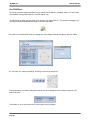
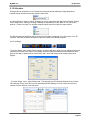
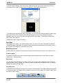
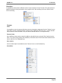
MyDMX User Manual
Revision 1.0
MyDMX V1.0
Table of Contents
1. General Information......................................................................................................... ..3
2. Installation...........................................................................................................................8
3. Getting Started..................................................................................................................10
4. Fixture Profiles..................................................................................................................11
5. List View........................................................................................................................... 14
6. Scenes..............................................................................................................................15
7. Triggering....................... ..................................................................................................17
8. Playback.................. ........................................................................................................ 19
9. Color Manager.................................................................................................................. 20
10. Effects Manager...............................................................................................................21
11. 3D Visualizer....................................................................................................................27
12. Appendix..........................................................................................................................35
13. Troubleshooting...............................................................................................................40
Page 2
MyDMX V1.0
Support
1. General Information
Thank You for Purchasing myDMX.
Thank you for your purchasing the American DJ myDMX PC control system. Please read the instructions
in this manual carefully and thoroughly before attempting to operate this unit. These instructions contain
important information regarding safety during use and maintenance. Please fill out and return the enclose
Warranty card to validate your purchase.
Customer Service
American DJ provides a toll free customer support line, to provide set up help and to answer any question
should you encounter problems during your set up or initial operation. You may also visit us on the web at
www.americandj.com for any comments or suggestions.
All returned service items whether under warranty or not, must be freight pre-paid and accompany a
Return Authorization (RA) number. The RA number must be clearly written on the outside of the return
package. Items returned without a RA number clearly marked on the outside of the package will be refused
and returned at customer’s expense. You may obtain a RA number by contacting customer service.
A brief description of the problem as well as the RA number must be written down on a piece of paper and
included in the shipping container. If the unit is under warranty, you must also provide a copy of your proof
of purchase invoice.
Customer Service hours are Monday through Friday 8:00 a.m. - 5:00 p.m. Pacific Standard Time.
Toll Free: (800) 322-6337
Phone: (323) 582-2650
Fax: (323) 725-6100
Information: [email protected]
Sales: [email protected]
Support: [email protected]
Forum: forums.americandj.com/eve
Page 3
MyDMX V1.0
Support
1-Year Limited Warranty
American DJ® hereby warrants, to the original purchaser, American DJ® products to be free of
manufacturing defects in material and workmanship for a period of 1 Year (365 days) on all internal parts,
components and labor from the date of purchase. This warranty shall be valid only if the product is
purchased within the United States of America, including possessions and territories. It is the owner’s
responsibility to establish the date and place of purchase by acceptable evidence, at the time service is
sought. For warranty service, send the product only to the American DJ factory. All shipping charges must
be prepaid. If the requested repairs or service (including parts replacement) are within the terms of this
warranty, American DJ will pay return shipping charges only to a designated point within the United States
except Hawaii or Alaska. If the entire instrument is sent, it must be shipped in its original Package. No
accessories should be shipped with the product. If any accessories are shipped with the Product, American
DJ shall have no liability whatsoever for loss of or damage to any such accessories,nor for the safe return
thereof.
This warranty is void if:
• The serial number has been altered or removed
• The product is modified in any manner which American DJ concludes, after inspection, affects the
reliability of the product
• The product has been repaired or serviced by anyone other than the American DJ factory unless
prior written authorization was issued to purchaser by American DJ
• The product is damaged because not properly maintained as set forth in the instruction
Manual.
This is not a service contract, and this warranty does not include maintenance, cleaning or periodic
check-up. During the period specified above, American DJ will replace defective parts at its expense,
And will absorb all expenses for warranty service and repair labor by reason of defects in material or
workmanship. The sole responsibility of American DJ under this warranty shall be limited to the repair of
the product, or replacement thereof, including parts, at the sole discretion of American DJ. All products
covered by this warranty were manufactured after January 1, 1990, and bear identifying marks to that
Effect.
American DJ reserves the right to make changes in design and/or improvements upon its products
Without any obligation to include these changes in any products manufactured thereafter.
No warranty, whether expressed or implied, is given or made with respect to any accessory supplied
with products described above. Except to the extent prohibited by applicable law, all implied
warranties made by American DJ in connection with this product, including warranties of merchantability
or fitness, are limited in duration to the warranty period set forth above. And no warranties, whether
expressed or implied, including warranties of merchantability or fitness, shall apply to this product after
said period has expired. The consumer’s and or Dealer’s sole remedy shall be such repair or replacement
as is expressly provided above; and under no circumstances shall American DJ be liable for any loss or
damage, direct or consequential, arising out of the use of, or inability to use, this product.
This warranty is the only written warranty applicable to American DJ Products and supersedes all prior
warranties and written descriptions of warranty terms and conditions heretofore published.
Page 4
MyDMX V1.0
General Information
Safety
The following safety information relates to the myDMX System. Please read each item carefully to ensure
you fully understand them.
To prevent the risk of electrical shock, do not open this unit. There are no user serviceable parts inside this
unit. Do not attempt any repairs yourself. Doing so will void your manufactures warranty. Should your unit
require service, please contact your nearest American DJ dealer or American DJ Customer Service.
To prevent or reduce the risk of electrical shock or fire, do not expose this unit to rain or moisture. Do not
remove the plug ground pin or connect to an ungrounded circuit.
This unit is not designed for use by persons under the age of 12. Use only under adult supervision.
Turn off the power if not using this unit for a long time.
Page 5
MyDMX V1.0
Abbreviations
The following abbreviations may be used throughout this manual.
CD – Compact Disc
DMX – Digital Multiple x
Mb – Mega byte
PC – Personal Computer
RA – Return Authorization
USB – Universal Serial Bus
XLR – 3-pin Cannon X connector, with Latch and Rubber guard
Page 6
General Information
MyDMX V1.0
Introduction
Introduction
myDMX Description
MyDMX was developed to be the simplest, PC based, DMX lighting control solution available in the
market today. The myDMX software is capable of controlling any type of DMX512 device through a
rugged DMX interface. A USB port on the interface provides for PC connection using the included USB
cable and a 3-pin DMX OUT connection for a standard 3 pin DMX cable. The DMX OUT provides
connection to DMX fixtures for playback operation. The software includes a vivid, user friendly display
which can be managed by a DMX novice. The software setup, programming of scenes and scene
playback is made simple by three easy to follow work tabs. Scenes can be programmed, renamed and
arranged as desired. MyDMX is also compatible with all midi controllers. Fixture channels and scenes
can be assigned and controlled through a midi controllers fader, potenciometer or button. This makes it
possible to control your entire light show externally. A 3D visualizer is included so you can set up your
own truss configuration and light shows then view them during playback. The 3D visualizer also gives
you the ability to program offline so when you get to your gig, you’re ready to go.
This manual is Copyright © 2008 American DJ Supply. All rights reserved. No part of the manual
included
with this product can be reproduced or transmitted in any form, by any means, for any purpose without
prior written authorized permission.
Information contained in this manual is subject to change at any time and without notice. Please contact
American DJ Customer Service or visit www.americandj.com for the latest manual revisions.
Minimum System Requirements
32Mb RAM video card to use the 3D visualizer supporting Microsoft DirectX 9.0
Laptop or desktop computer with USB port
Windows ME, XP, or any up to date version
256Mb Memory
800 x 600 screen resolution
800 Mhz clock frequency
Best Performance System Requirements
128Mb RAM video card to use the 3D visualizer supporting Microsoft DirectX 9.0
Laptop or desktop computer with USB port
Windows ME, XP, or any up to date version
512Mb Memory
1280 x1024 screen resolution
1.5GHz clock frequency
Page 7
Installation
MyDMX V1.0
2. Installation
Unpacking Contents
When first opening your myDMX packagae, please ensure that all components are present. The system
Ships with the following components:
• myDMX USB to DMX interface
• USB Cable
• myDMX System Control Software CD
• myDMX User Manual
Upon unpacking, carefully inspect your unit for any damage that may have occurred during shipping. If
damage has occurred, do not plug the unit in. Contact your American DJ dealer as soon as possible.
Do not discard packing carton in the trash. Please recycle when ever possible.
Cabling Requirements
The USB cable provides power to the myDMX interface and should be connected to a USB port on your
PC.
Figure 1
MyDMX
Computer
(NOT INCLUDED)
USB CABLE
Interface
DMX DATA
CABLE
DMX
Fixture
(NOT INCLUDED)
DMX DATA
CABLE
DMX
Fixture
(NOT INCLUDED)
DMX Data cabling should meet the following USITT DMX512 specification requirements such as ACCU
CABLE, DMX cables:
• Low capacitance
• Two twisted pairs
• Foil or braid shielded
• Suitable for use with EIA485 (RS485) operation at 250k baud
• Characteristic impedance 85-150 ohms, nominally 120 ohms
• 24 AWG min. gauge for runs up to 1000 feet (300m)
• 22 AWG min. gauge for runs up to 1640 feet (500m)
Microphone cables and other general purpose, two-conductor audio or signal cables are not suitable for
use with DMX512.
Page 8
MyDMX V1.0
Installation
USB Driver Installation
1. Insert the myDMX Software CD into a CD drive on PC.
2. Locate the adj.exe application on the CD and double-click to begin installation.
Windows will find the driver and will tell you the device is not validated, and will ask if you wish to
continue. Although Microsoft does not have a numerical registry for this driver, there is no risk of
incompatibility. Click "Continue Anyway".
Page 9
MyDMX V1.0
Installation
Keep in mind that the software detects the USB interface when it launches. This means that
you must have the USB interface connected to your computer each time b efore launching the software.
Otherwise, there will be no communication between the software and the interface. Click “Finish” when
The wizard has competed the driver installation.
Page 10
MyDMX V1.0
Getting Started
3. Getting started
Software Launch
1. Double click the myDMX desktop icon. Note: if you do not have an interface connected to the PC, the
Software will launch in “Demo” mode and you will not be able to control any fixtures. If an interface is
Connected thereafter, the software will not recognize it. If this happens, you must close the myDMX
Program, connect the interface USB cable to the computer then re-launch the software.
There is no DMX output when the software is launched in this mode.
myDMX interface is connected and DMX signal should be present.
Page 11
MyDMX V1.0
Set Up
4. Fixture Profiles
The myDMX software includes thousands of pre-created fixture profiles from most brands available in the
market today. The fixture profiles include detailed channel information that allow for proper and precise
control of your lighting fixtures. Profiles are created using the Scan Library Editor program which is
included with the myDMX software package. American DJ will do its best to create and post new fixture
profiles to the American DJ, myDMX webpage on a regular basis. However, you may use the Scan Library
Editor should you feel the need to edit an existing profile or create a new fixture profile not yet available.
Adding Lighting Fixtures
Use the ScanLibrary menu on the upper left of the Set Up screen to select the fixture or fixtures that
you wish to control.
1. Locate the manufacture folder by using the scroll bar on the right and left click the plus sign next to the
folder to access the available fixture profile list.
2. Left click the fixture name once which should now be highlighted in blue.
3. Select the starting DMX channel that you want your fixture or fixture group assigned to in the
“First DMX channel” section.
Note: if you cannot see these options which should be located below the fixture folders, find the
scroll bar on the right and scroll down to access them.
4. Define the number of fixtures that you want to add by typing in or selecting the quantity from the
drop down tab in the “Number of fixtures” section.
5. If you wish to create a matrix of selected fixtures, left click the “Matrix” button and enter the # x #
information for your matrix. This feature is most commonly use with RGB LED walls. Continue on to
step 6 to finish adding your fixture.
Page 12
MyDMX V1.0
Set Up
6. Enter a starting Index number that you wish to assign to your fixtures. The Index number is simply
a number that will automatically be assigned to each fixture to make it easier for you to recognize it
during the programming process. For example, if the Index # is set to 1, and (4) Accu Scan 250
fixtures are added, the index numbers will display as “accu scan 250.1 , accu scan 250.2,
accu scan 250.3 and accu scan 250.4 ... See diagram below.
7. Left click the “Patch” button to add the fixtures. Like the picture shows above, your fixtures will
automatically be added to the grid. To add additional fixtures, repeat steps 1 thru 7.
You can also drag and drop fixture profiles directly from the Scan Library folders onto the DMX grid
like pictured below. If you use this method of adding fixtures, be sure to drop each fixture onto
available DMX channels. Available DMX channels are white boxes with black numbers on them.
Page 13
MyDMX V1.0
Set Up
5. List View
Above the DMX patch area, there is a pull down menu, with the "Grid View" option selected. Change
this to "List View" to access some advanced fixture configuration options.
These options include the following:
- Channel Shortcut Keys
- to control channels directly with the computer mouse at any time by holding any key on your
computer keyboard, you can change them at any time by clicking on the corresponding Shortcut area
for each channel.
- Enable Channel Fade
- if not selected, the fade time between 2 steps or scenes will not affect the corresponding channel
(very useful for Gobo channels, for example, where you want only the position to fade slowly, but the
gobos to change quickly)
- Enable Stand Alone Dimmer
- if your interface has internal memory and 3 external buttons, you can press and hold the 3rd button
[arrow] along with either the [+] or [-] buttons to adjust the dimming level
-Invert Pan/Tilt, Swap Pan/Tilt
- each of these options allow you to invert Pan/Tilt control, or swap Pan with Tilt, ONLY when they are
being controlled using the keyboard shortcuts and mouse described above.
Page 14
MyDMX V1.0
Scenes
6. Scenes
With myDMX, you can create dynamic scenes by storing multiple steps that each include individual fade
and wait times. Fade and wait times can be set between 0 and 43 minutes each. A scene can include up
to 1,000 steps each. The number of loops that a scene plays can also be set followed by the next scene
to be triggered. This allows you to ultimately structure a show so scenes can automatically trigger during
playback. A show can include up to 255 scenes and the number of shows that can be created and saved
is only limited to the memory of your computer.
To create scenes, you must be in the editor screen. Left click the “Editor” tab as pictured below.
Scene Section
This section lists all recorded scenes, loop, fade and trigger information for each. It also includes a
toolbar that allows you to do the following:
· create a new scene
· copy a scene
· delete a scene
· rename a scene
· assign a keyboard hot key (See triggering section on page 17)
· change scene priority position
· play a scene in real time
By default, scenes are always set to continuously loop. You can specify a specific number of loops,
And the scene to trigger when finished.
Page 15
MyDMX V1.0
Scenes
Step Section
The step section displays all of the steps associated with the selected scene. In addition, the selected
scene fade and wait times are also displayed there and can be edited at any time. The steps in this section
can be manually created or automatically created when using the “FX” generator. The functions found in
the toolbar are as follows:
· add a new step
· copy the selected step
· paste step
· delete the selected step
· Set Levels button
Each scene includes a number of steps which will fade in sequentially. Each step represents a cue on
all the channels which fade time and wait time are associated with it. For example:
· if you wish to have your lights move in a triangle movement, you will have to create 3 steps and
Specify fade time for each step.
· if you wish to create a static scene, only one step is necessary.
Fixture Channel Fader Section
Various methods can be used to set channel-levels:
· drag channel-fader with the mouse.
· if the channel has been assigned a keyboard shortcut, press key and move the mouse.
· if the channel has presets (e.g. : gobos, colors...), right-click on channel name to make a selection
from a list.
· set several channels simultaneously by pressing "Set levels" button in the Step section.
· if the channel is a color mixing channel, (RGB or CMY), right click to open the Color Manager window.
You can change the DMX levels of multiple channels simultaneously:
· Left click a specific channel name, press and hold the SHIFT key then move the channel fader of the
Selected channel. Fixtures of the same type channels will simultaneously change.
· Hold the CTRL key pressed and select the channels (left button of your mouse) you want to use. Hold
The left button pressed on the last selected channel and move your mouse to change the level
· Select a channel, press and hold the SHIFT key and then select a second channel. This will select all
The channels between the first selected and the last one
Page 16
MyDMX V1.0
Triggering
7. Triggering
Keyboard Triggering
To trigger scenes using hot keys, click the “Trigger” icon which will open the “Trigger - New Scene”
Screen. Type the key that you wish to trigger the selected scene with in the “Key” box. See below.
Midi Triggering
The Midi trigger function is a powerful tool that allows for LIVE playback of scenes that you’ve programmed
and fixture channel control. Any standard MIDI controller, such as the unit pictured below, can be connected
to your computer and linked to trigger scenes in your myDMX software.
Be sure to connect your MIDI controller to your computer before launching the myDMX program so that
it is recognized by the software. Once you’ve programmed your scenes, it’s simple to assign MIDI
controller faders, potentiometers or buttons to externally trigger them. In addition, fixture channels can
also be assigned and controlled externally via MIDI.
Page 17
MyDMX V1.0
Triggering
From the user screen,
Right click on a scene or channel fader that you wish to assign to the midi controller.
Left click on the “Learn MIDI command...” Prompt.
Move, turn or push a fader, potentiometer or button on the midi controller that you want your relevant
scene or fixture channel assigned to. The “Waiting of MIDI command...” prompt will disappear which
confirms that the scene or fixture channel was successfully assigned. To play the assigned scene or
move the assigned fixture channel from your midi controller, simply trigger the relevant fader,
potentiometer or button on the controller.
Page 18
MyDMX V1.0
User
8. Playback
To playback scenes that you’ve created, you must be in the “User” screen. Left click the User tab>
1 - Button-area
Each button represents a "scene" which can be activated with the mouse. If the button is pressed, then
the scene is activated. Each button is also used to visualize the number of loops and various triggers.
2 - "Previous", "Next" and "PLAY CYCLE" functions
By clicking here, you can trigger the previous or next scene in accordance with the order made into the
editor. You can also activate "Cycle" mode which enables you to automatically go from a scene to the
next one. Of course, this mode can only apply on "go automatically to next scene" scenes.
3 - AUTO/LTP/HTP functions
By clicking here, you may manually control the different channels. 3 modes can be used:
· AUTO : the channel works automatically on the current scene. The manual cursor is de-activated.
· LTP : the channel is in "Latest Takes Priority" mode, the level is that of the cursor. The current scene
Has no effect on the channel.
· HTP : the channel is in "Highest Takes Priority" mode.
Page 19
MyDMX V1.0
Color Manager
9. Color Manager
The "Color Manager" tool is basically a color editor for RGB or CMY fixtures. It allows you to create
either static or dynamic color sequences very easily. Imagine you want to load a bitmap or simply write
a text on your matrix of LEDs, "Color Manager" will help you to make it in a few seconds. To open
"Color Manager", right click on a color mixing channel in the Editor screen. Several functions are available.
Basic tools
The basic tools are situated in the "Tools" area of the window. You can find the main functions available
in a bitmap designer and select a color for each fixture very quickly. Each fixture is represented by a
square on the left side. There following tools are available.
- Select pixel and Select area: the first one allows to select fixtures one by one, the second allows to
select several fixtures simultaneously
- Pen and Paint bucket: to paint one or several pixels with the selected color
- Line, Rectangle, Circle: to draw a line, a rectangle or a circle
- Pipette: to pick a color from the fixtures area
- Copy, Paste: to copy or paste pixels
- Load an image: to draw an image (BMP, JPG...) with your fixtures
You must use the color picker to change the color of the selected pixel(s). You can also enter the
RGB values manually.
Page 20
MyDMX V1.0
Effects Manager
10. Effects Manager
The Effect Manager is an extremely powerful tool which allows you to easily create stunning effects with
your lights without having to go through the laborious process of programming each individual step and
scene. Once you have created your effect with these simple to use tools, you just need to click “generate”
and the software will automatically create the steps required.
The Effect Manager adapts it’s self depending on the fixtures you are using. To demonstrate the capabilities
of this tool, we’ll start by using a matrix of generic RGB LED color mixing fixtures.
To access the effects editor, left click the “FX” button.
Page 21
MyDMX V1.0
Gradient Editor
The gradient editor allows you to create many complex static gradients.
Switch the editor ON by clicking on the red button and select a gradient type and range.
Editing the color of a gradient
In this example we have created a fade between blue and green.
Select the color you wish to edit.
Choose your color from the drop down box.
Page 22
Effects Manager
MyDMX V1.0
Effects Manager
Changing the length of a gradient
Here we see an even gradient between blue and green. You may wish for the gradient to be long at the
beginning and then short. To achieve this, we can create a gradient step by double clicking on a
particular part of the gradient. A point will then appear. You can drag this point along to change the
gradient.
Adding a color to a gradient
You can use the points to add multiple colors to the gradient. For example, we may want the gradient to
fade from blue to white, and then from white to green. This can be achieved by selecting the point and
changing the color from the drop down box.
If you are unhappy with the points added, simply select the point and click the “delete” button.
Remember to click generate before closing the effect manager.
Color Mixing
The color mixing tool is the easiest way to create complex color effects. Firstly switch the tool on and
select an effect. Click the preview button, eye ball, to see how your final effect will look.
You can vary the size, speed and direction of the effect as well as changing the colors used by clicking
the pallet icon. You can also change the number of colors used. Remember to click generate before
closing the effect manager.
Page 23
MyDMX V1.0
Effects Manager
RGB Matrix Effects
This tool is specifically designed for use with a matrix of LED panels. To get started, click the “+” button
to add a layer. The layer name can be changed by double clicking it and there are several layer types
available, the most basic being color. The color can be changed by clicking the pallet. Moving shape
effects can also be created by selecting “effect” from the drop down box.
Image and video
The effect manager is capable of reading a jpg, bmp or gif image and interoperating this on an LED
matrix. Select picture from the “type” drop down box and load your photo. You can choose to stretch
your photo filling up the full matrix, or to keep its original proportions. If you wish to go a step further, AVI
video can also be played.
Text
Selecting “Text” in the drop down box opens the text editor. Here you can enter a piece of text and
choose where to place the text on your LED matrix. You can also scroll the text by clicking one of the 4
arrows and adjust the scroll speed. Clicking the “T” button allows you to change the font. To change the
text color and background, select the color pallet.
Remember to click generate before closing the effect manager.
Page 24
MyDMX V1.0
Effects Manager
Advanced Effects
This tool allows you to have more control over the individual channels of your fixtures and is extremely
usefull with moving heads and scanners as well as LED’s. To demonstrate the advanced effects section,
we will insert 8 generic moving head fixtures. You will notice that when inserting the moving head fixture,
the effect manager interface adapts itself. The new fixtures channels are displayed and the “RGB matrix
effects” tab is replaced with a “Pan/Tilt effects” tab.
Firstly, you’ll need to click “light beam on”. This sends a message to all the relevant shutter/iris/dimmer
channels to show the light beam.
Select the channel you wish to apply your effect to. Here we have applied an effect to the dimmer
channel.
Next, choose a waveform from the dropdown box, here we have chosen a sinus wave. You can
preview your scene in real-time using the 3d Visualiser. Adapt the wave settings and choose if you
wish to have all your fixtures synchronised or phased, then click “generate”.
Page 25
MyDMX V1.0
Effects Manager
Pan/Tilt Effects
As well as using the “advanced effects” tool to create Pan/Tilt effects by creating waves, you can create
more specific moving effects with the “Pan/Tilt effects” tool.
As with the other effect manager tools, you’ll need to click “light beam on”. This sends a message to all
the relevent shutter/iris/dimmer channels to show the light beam.
Once the tool is switched ON, start by creating one of the shapes listed and hit play to test your effect.
You can edit your shape by adding, deleting and moving the points.
To slow/speed up your effect, change the interval time, this changes the time it takes to get from one
point to the next.
Remember to click generate before closing the effect manager.
Page 26
MyDMX V1.0
3D Visualizer
11. 3D Visualizer
3D stages are saved with the "evs" format and can be open/saved indefinitely. Stage dimensions,
inserted objects and fixtures are also saved in these files.
It is also possible to import or export 3D stages to or from zipped files with the "Import / Export" buttons
of the "Stage" menu. Saving a 3D stage including all required files (X files, BMP or JPG files for the
textures...) and the re-open it on another computer which does not contain the same objects.
The following section describes how to create your first stage, introducing you to the basics of our 3D
visualizer. It will also include a description of the files used to save different projects.
Your First Stage
- From the “Stage” menu, select “Stage settings.” A window will open, where you can adjust the size and
color/texture for each of the walls on your stage. Notice the options available to select individual walls,
show or hide walls, repeat textures in both the X and Y axis, and change units between metric and
English.
- From the “Stage” menu, select “Build mode.” This will split your 3D visualizer window into 4 sections:
3D rendering, 2D top view, 2D front view, and Object/Fixture Settings. You can control the size and
content of these sections, even hide them.
Page 27
MyDMX V1.0
3D Visualizer
- From the “Object Settings” section click on the “Add object” button (grey cube next to the red arrow in
the picture above) to insert an object from our libraries (i.e. /Music Instrument/Drums.x)
- The object will be inserted at the center of the stage. You can move this object around the 3D stage using
your mouse. Furthermore, using the object editing tools (green arrow) you can change the position,
orientation, size, color, etc. of any object selected from the list (blue arrow). These tools are explained in
later sections of the manual.
- Repeat these steps to add more objects.
User Mode
The software has 2 modes : User mode and Build mode. The first one is for the visualization, all features
to modify the stage are disabled. This chapter introduces all features dedicated to the visualization, even if
most of them are available from the Build mode as well.
Rendering Options
Several options are available to customize your stage and the rendering. All of then are in "Options" menu.
Ambient lighting
It is possible to modify the intensity of Ambient lighting with the faders located on the "Options toolbar"
("View" menu, "Options toolbar").
Fog density
You can adjust the fog density on your stage. To do so, you must go to the "Light beam" menu ("Options"
menu) and select "UP" or "DOWN". You can also modify the density from the "Options toolbar" or using the
keyboard shortcuts LEFT and RIGHT.
Rendering mode
It is possible to switch between "Normal" and "Powerful" rendering mode. The software starts automatically
in "Powerful" mode if your graphic card is compatible. However you can switch to the "Normal" mode if you
think that it runs too slowly.
Page 28
MyDMX V1.0
3D Visualizer
Resolution
It is possible to choose from 5 different levels of screen resolution for the 3D views. This option allows to
adapt the software to the performance of your graphic card. If the rendering is too slow, select a lower
level of rendering.
Cameras
Views
It is possible to move the camera with the mouse (see the buttons assignment from the "Options" menu)
if the "Move" option is selected from the "Camera" menu. Differents views (front, left...) can be selected
from the menu or from the toolbar. They can also be selected with the 1 to 5 keyboard keys.
Personal views
Up to 4 different views can be created in addition to the default ones, using the "Save" option from the
menu. The current view (position and orientation) will be then saved. Those view can be called from the
menu or with the 6 to 9 keyboard keys.
Auto rotation
An auto rotation option is available from the "Camera" menu or the 0 keboard key.
ScreenShot
Page 29
MyDMX V1.0
3D Visualizer
Build Mode
This chapter introduces the second mode of the software : Build mode. The screen is split and contains
the 3D view, the "Objects settings" window, and the 2D views.
Stage Size & Color
Color and dimensions of stage (width, height and depth) can be defined within this window (available
from the "Stage" menu or from the standard toolbar).
Color & Textures
First you must select the face or select all faces to make your stage unicolored. To change colour,
remove "x" from the "default" checkbox, then select the colour from the following window.
As for the color, you must unselect the "Default" option to choose a texture for the walls. Select the image
(BMP or JPG) by clicking on the "..." button. You can also make your texture repeating (horizontally and
vertically) by using the "Texture repetition (X and Y)" controls.
Units
Inserting Objects
Page 30
MyDMX V1.0
3D Visualizer
The library on the left side displays the available objects to be inserted. Once selected, the object
automatically appears in the visualization window. The object selected may be previewed before it is
inserted. Click on "Select" to insert the object in your stage.
All the 3D objects available in the software are situated in the objects library. However you can use your
own objects (X format). It is better to use simple objects because it is a real-time application and big
objects can make the program run slowly.
If you want to insert objects coming from another library, you will have to choose whether you want to
copy the object in the library.
Insert Fixtures
As for the objects, the software makes it possible to insert fixtures from the library by clicking on "Add
fixture(s)" from the "Stage" menu or from the standard toolabr. The following window appears :
Select a fixture from the list and then patch it using the "Patch" button after having specified the starting
DMX address and the number of devices or by drag&drop. Make sure you select the correct universe first
by selecting the right tab.
It is also possible from the toolbar or by clicking with the right button of the mouse on a fixture to :
- copy/paste fixture(s)
- duplicate fixture (s) with a wizard
- rename a fixture
- delete fixture (s)
All actions can be canceled with the UNDO button.
To select a fixture, click on it or click and draw a selection rectangle. Then, moving the selected fixture (s)
becomes possible by holding the left button of the mouse. To move a fixture to another universe, just drag
it to the corresponding tab and this will open the new universe.
When controlled by another sofware, the 3D visualizer can receive the patch informations directly. 2
modes are available :
"Automatic" mode will insert all fixtures from the controller patch and remove the current devices of the 3D
visualizer that are not in the controller.
“Manual" mode, allows to patch any fixture coming from the controller or not (several fixtures can be
patched to the same DMX address)
Page 31
MyDMX V1.0
3D Visualizer
It is better to use this window only in "Automatic" mode to not lose all changes made before. The list on
the left side shows the fixtures informations received from the controller. The "orange" fixtures are those
available in the controller and already patched in the 3D visualizer, the "blue" are those patched in the 3D
visualizer and not in the controller. The user can select the devices he want to insert or not. Click on
"Patch" to insert the selected fixtures.
The 3 options allow to select the patch mode and 2 display options. Here they are :
· to show only the fixtures available in the controller and not patched in the 3D visualizer or the entire
patch
“automatic" or "manual" patch
display or not the popup window when the patch has changed
Simple Objects Editor
This tool enables you to create your own objects and reuse them later on:
Page 32
MyDMX V1.0
3D Visualizer
Three different types of objects can be created:
· Cube
· Sphere
· Cylinder
You can modify dimensions and then save them under the Microsoft X format. The "Flat" option enables
you to add 2 cm in height and to quickly create a rectangular or circular screen in shape and reuse it over
and over again in your future stages.
Textures
You can also add a texture to an object. You must unselect the "No" option to do so. Then, you just have
to select an image by clicking on the "..." button.
Object Settings
Moving objects or fixtures
In this window, objects and fixtures can be shifted individually or in a group using the multi-selection
mode. There are six different settings available: three movements on the X, Y, Z axis (width, height and
depth of the stage) and also three rotating movements around these very axes. Thus, objects can be
positioned as they actually are on your stage. You must open the "Location" tab to do so and select
objects and fixtures from the list (see below). The last tab allows to simply setup the positions of the
fixtures in line, circle, rectangle...
Changing size and colour of objects
We must go to the "Size" and "Color" tabs to change these settings. It is possible to modify the
transparency of a 3D objects, this can be very useful to create a window...
Page 33
MyDMX V1.0
3D Visualizer
Fixtures List
The list is located in the "Objects" tab of the "Objects settings" window. All fixtures are listed and folders
can be created to simply classify them. The drag& drop is used to move the fixtures within the list. To add
a new folder, click on the "New folder" button from the toolbar. The up and down arrow allow to expand or
collapse the list.
To rename a fixture, double click on it and then enter the new name. It is also possible to select another
layer for the fixtures by double clicking on the layer cell and selecting a layer from the list.
The list shows information that can not be modified like the name of the profile, or the DMX address and
some options that can be modified like the beam color, the frost effect and gives the possibility to invert
PAN/TILT channels.
The 4 last columns are :
- Gel color (can be modified by clicking on the color)
- The frost effect (a frost effect is available for every fixture)
- Invert Pan
- Invert Tilt
Duplicate objects
By resorting to the "Duplicate" function, you can edit in and quickly position one or several objects. For
example, imagine that you have designed a set of truss elements in circle and that you would like to carry
out the same layout at 4 meters away on the left side... The "Duplicate" function enables you to reinsert
the whole set of objects and to move them proportionally in order to get a similar layout. Now, you can
select your first group of objects (referred to as "circle 1") and by a simple mouse click, make the
following "Duplicate" menu appear on the screen.
Page 34
MyDMX V1.0
3D Visualizer
Objects List
The list is located in the "Objects" tab of the "Objects settings" window. All objects are listed and folders
can be created to simply classify them. The drag & drop is used to move the objects within the list. To add
a new folder, click on the "New folder" button from the toolbar. The up and down arrow allow to expand or
collapse the list.
To rename an object, double click on it and then enter the new name. It is also possible to select another
layer for the objects by double clicking on the layer cell and selecting a layer from the list.
Note: It is possible to display or not each column of the list by clicking on the title bar with the right button
12. Appendix
This chapter introduces all the menus, toolbars and shortcuts of the software. The last trouble shooting
section shows what to check/do in case you experience a problem with the software.
Menus summary
· Create a new 3D stage
· Open a 3D stage
· Save the 3D stage
· Save the 3D stage with another name
· Import a 3D stage
· Export a 3D stage
· Print
· Print preview
· Print properties
· Open the Construction mode
· Open the User mode
· Open the "Stage settings" window
· Open the "Simple objects editor"
· Add fixtures
· Exit the software
Page 35
MyDMX V1.0
3D Visualizer
Camera
· Front view
· Right view
· Left view
· Top view
· Rear view
· Move the camera
· Auto rotation
· Create a screenshot
· Open the "Movie recorder" window
· Save the current position of the camera
· Delete the selected camera
· Custom camera 1
· Custom camera 2
· Custom camera 3
· Custom camera 4
View
· Always visible option
· Display or not the the lower half of the screen
· Display or not the the right half of the screen
· Display the standard toolbar
· Display the camera toolbar
· Display the options toolbar
· Display the zoom toolbar
· Display de mouse toolbar
Language
· Change the sofware language...
· Open the "About" window
· Start the online help
Page 36
MyDMX V1.0
3D Visualizer
Toolbars Summary (Left to Right)
Standard toolbar
· Create a new stage
· Open a stage
· Save the stage
· Always visible option
· Open Construction mode
· Open User mode
· Add new fixture(s)
· Open the DMX input window
· Open the stage settings window
· Open the simple objects editor
· Undo
· Redo
Options toolbar
· Adjust ambient lighting
· Adjust the fog intensity
· Change the rendering level
· Enable/disable the "laser" rendering
· Enable/disable shadows
Camera toolbar
· Open the movie maker window
· Create a screen shot
· Camera menu
Zoom toolbar
· Zoom menu (assign a zoom function to the left button of the mouse)
· Fit
· Zoom OUT
· Zoom fader
· Zoom IN
Page 37
MyDMX V1.0
3D Visualizer
Shotcut Keys
0 Automatic rotation
1 Front view
2 Right view
3 Left view
4 Top view
5 Rear view
6 Camera 1 (personal)
7 Camera 2 (personal)
8 Camera 3 (personal)
9 Camera 4 (personal)
* Move camera
Esc Quit the software
Delete- Delete selected fixtures or objects
Ctrl+'N' Create a new 3D stage
Ctrl+'O' Open an existing 3D stage
Ctrl+'Z' Undo
Ctrl+'Y' Redo
Here is a list of first things to checked in case you experience problems with the 3D visualizer.
Please check that Microsoft DirectX 9b or any up to date version is installed on the computer.
Make sure that graphic cards drivers are correctly installed.
Under Windows XP, please check that the hardware acceleration is at full in the "Troubleshoot" tab of
the graphic card advanced properties window.
If DirectX is correctly installed, enter "DXDIAG" in the "Run..." section of the "Start" menu. In the
"Dispaly" tab, please check that the following features are enabled: DirectDraw acceleration and
Direct3D acceleration.
Page 38
MyDMX V1.0
Troubleshooting
13. Troubleshooting
Software and/or interface do not work
1. Check the USB interface
Connect the interface to the computer. You should see 3 LEDs turn on, green, yellow, and red. Green
should be blinking slowly. Yellow should be completely on. Red should be blinking fast.
If non of the LEDs are on, check the back of the interface, there is a small switch that turns power
ON/OFF. If only the yellow LED is on, then your interface is broken, please contact your retailer to have it
replaced.
2. Check software/interface communication
Connect the interface to the computer BEFORE you start the software. After you open the software, the
green LED should start blinking fast. If you go to the “?” menu, then “About”, a popup window will appear
with our logo in it. You should be able to read software name and a release date for the software. If there
is good communication between the software and the interface, you should see a description of your
interface inside this box as well.
If the green LED is not blinking fast, or you do not see the red letter description, there is no
communication between the software and the interface. You probably did not install the drivers correctly.
3. Check the interface drivers
If you are using Windows XP, reconnect your interface to any USB port (a different one, if possible).
Windows will tell you whether the hardware found is new or already installed in your computer.
If it is new, the NEW HARDWARE WIZARD window will appear. Insert the installation CD in your
computer, and select Automatic Search (if you do not have the installation CD, go to the
Support/Downloads section in our website). Click “Continue Anyway” when Windows asks you about
verification.
After this, Windows should tell you that your device is ready to be used. Restart the software and check
communication (previous step).
4. Double-check interface drivers
If during the installation of the drivers, when asked about Windows verification and compatibility, you
selected "Stop installation" instead of "Continue anyway", the drivers will not be installed correctly.
To check if the drivers were installed correctly, you should go into
- Windows Control Panel - System - Hardware - Device Manager
You will see a list that includes all USB devices. If the interface is connected and the drivers are installed
correctly, the name of the device will be "Intelligent Usb Dmx Interface". If, on the contrary, you read
"Unknown device" with a yellow exclamation point next to it, the drivers are not installed correctly.
To fix this:
- Uninstall unknown device
- Disconnect USB interface, wait a couple seconds, and reconnect
- The "Add New Hardware Wizard" will appear, just follow the instructions (previous step)
- Make sure you select "Continue anyway" when asked about Windows verification and compatibility
5. Test on a different computer
If nothing seems to work, please try testing on a different PC before contacting your retailer to get an
exchange. Typically, you should only ask for an exchange if:
- No LEDs turn on, even when you have moved the power switch in the back of the interface
- Only the yellow LED turns on
- The drivers seem to be installed correctly, but the interface/software does not work, and the Device
Manager name for the USB device is "SUIDI-OUT" instead of "Intelligent Usb Dmx Interface”
Page 39