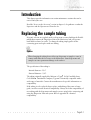
1
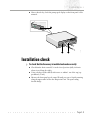
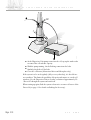
QS Small Volume Sample Dispersion Unit MAN 0161 Issue1.1 April 1997 ©Malvern Instruments Ltd. 1995, 1997 Malvern Instruments makes every effort to ensure that this document is correct. However, due to Malvern Instruments policy of continual product development we are unable to guarantee the accuracy of this, or any other document after the date of publication. We therefore disclaim all liability for any changes, errors or omissions after the date of publication. No reproduction or transmission of any part of this publication is allowed without the express written permission of Malvern Instruments Ltd. Head Office: Malvern Instruments Ltd. Spring Lane South, Malvern. Worcestershire. WR14 1XZ U.K. Tel + [44] (0) 1684-892456 Fax + [44] (0) 1684-892789 Printed in England CONTENTS Contents Chapter 1 - Introduction to this manual Access to the Accessory 1.1 Malvern personnel 1.1 Supervisor 1.1 Operator 1.1 Systems covered by this manual 1.1 Assumed information 1.2 Windows terms 1.2 Menu Commands 1.2 Where to find information 1.3 Other reading 1.5 Chpater 2 - Health & safety Introduction 2.1 Site requirements 2.1 Laser safety 2.2 General laser safety 2.2 Laser Warnings 2.2 Electrical safety warnings 2.3 Sample handling 2.3 Moving the Accessory 2.5 Repackaging the Accessory 2.5 Disposing of the Accessory 2.6 Chapter 3 - Installation Q S S M A L L Introduction 3.1 Site requirements 3.1 V O L U M E S A M P L E D I S P E R S I O N U N I T Page i CONTENTS Q S S m a l l V o l u m e S a m p l e D i s p e r s i o n U n i t Unpacking the Accessory 3.2 Checking the contents 3.3 Connecting up your Accessory 3.4 Mastersizer S and X 3.4 Mastersizer Micro and Microplus 3.6 Power up the Accessory 3.8 Installation check 3.9 Chapter 4 - Getting to know your Dispersion Unit Introduction 4.1 Features of the Accessory 4.1 Controller Unit rear panel 4.3 The Malvern software 4.4 Qspec MS1 macro 4.4 Chapter 5 - How the Accessory works Introduction 5.1 What does the Accessory do? 5.1 How does the Accessory do it? 5.1 Operating principle 5.1 How to make a measurement using the Accessory 5.2 Chapter 6 - Making a measurement using the Accessory Page ii Introduction 6.1 System and Accessory preparation 6.1 Making a measurement 6.1 M A N 0 1 6 1 CONTENTS Chapter 7 - Creating and changing SOP’s Creating a new SOP 7.1 Editing and deleting a SOP 7.5 Chapter 8 - Sample preparation Introduction 8.1 Trapped air/bubbles 8.1 Using a slurry 8.2 The use of ultrasonics 8.2 Chapter 9 - Maintenance Introduction 9.1 Replacing the sample tubing 9.1 Replacing the fuse 9.2 Cleaning the Accessory 9.2 Disassembly 9.3 Cleaning 9.4 ‘O’ ring seals 9.4 Reassembly 9.4 Cleaning the cell windows 9.5 Appendix A - Specification Introduction A.1 Appendix B - Chemical compatability Q S S M A L L Introduction B.1 Components in contact with sample and dispersant B.1 V O L U M E S A M P L E D I S P E R S I O N U N I T Page iii CONTENTS Q S S m a l l V o l u m e S a m p l e D i s p e r s i o n U n i t Appendix C - Simple fault finding Introduction C.1 Fault diagnosis and correction C.1 Appendix D - Installing the Qspec MS1 macro Introduction D.1 Appendix E - Statement of EMC performance Statement of EMC performance Page iv E.1 M A N 0 1 6 1 Introduction to this manual C H A P T E R 1 CHAPTER 1 Access to the Accessory Within this manual reference is made to the various people that will have access to the Accessory. Below is a list of these people and their responsibility: Malvern personnel Malvern personnel (service engineers, representatives etc.) have full access to the Accessory and are authorised to perform all service procedures that may be required. Supervisor The supervisor is the person responsible for the management/safety of the System and of its operation. The supervisor is responsible for the training of the operators. The supervisor can perform all user maintenance routines identified in chapter 9, including changing the fuses. Operator An operator is a person trained in the use of the system. The operator can perform all user maintenance routines identified in chapter 9, except changing the fuses. Systems covered by this manual This manual covers the installation, operation and maintenance for the QS Small Volume Sample Dispersion Unit. This accessory is used in association with various Mastersizer optical units. Mastersizer is a generic name given to a family of systems. Each system within the family uses the same principles of operation and only vary in operation in small areas. For this reason the manual has been written to cover more than one instrument. Q S S M A L L V O L U M E S A M P L E D I S P E R S I O N U N I T Page 1.1 CHAPTER 1 Q S S m a l l V o l u m e S a m p l e D i s p e r s i o n U n i t This manual covers the Accessory in association with the following Mastersizer family members: Instrument. Ref. Number. Mastersizer X standard bench. MAM 5000 Mastersizer X long bench. MAM 5002 Mastersizer S standard bench. MAM 5004 Mastersizer S long bench. MAM 5005 Mastersizer Micro. MAF 5000 Mastersizer Microplus. MAF 5001 Assumed information For clarity this manual will assume that you are using your Accessory in association with a standard bench Mastersizer S. If there are any operational procedures that differ when in use with another Mastersizer family member, the alternative information will be given. Within this manual the QS Small Volume Sample Dispersion Unit will be referred to as the “Small Volume Sample Dispersion Unit”, or as the “Accessory”. Throughout this manual the Small Volume Sample Dispersion Unit refers to the Dispersion Unit & the Controller Unit. Within this manual the Mastersizer system will be referred to as the “Mastersizer” or the “system” unless the information given is for a particular instrument. Windows terms It is important that you understand some windows terms before reading further. Refer to chapter 1 of the Getting Started manual. Menu Commands Menu commands from the Malvern software are referred to in the form main menu-menu item. As an example, the command Setup-Hardware refers to selecting the Hardware item in the Setup menu. The same rules apply for sub-menus of sub-menus. Menu commands are always shown in bold text. Page 1.2 M A N 0 1 6 1 CHAPTER 1 Where to find information As stated above, this manual is designed to give a brief overview of what the Accessory can do and how it is used in association with the system. In other words it is a quick guide that allows you to understand how the Accessory operates and runs you through how the Accessory is used when making a measurement, hopefully steering you around the main pitfalls and directing you to more information if needed. The following is a list of the contents and objectives of the chapters within this manual. Chapter 2 - Health and Safety This chapter covers health and safety guidelines that should ensure the safe installation, operation and maintenance of the Accessory. You should read this chapter in conjunction with the Health and Safety manual for your Mastersizer system. You are provided with information on: . Laser safety. . Electrical safety. . Sample handling. . Moving the Accessory. . Disposing of the Accessory. Chapter 3 - Installation This chapter provides you with all information required to install the Accessory and includes information on: . Positioning the Accessory. . Unpacking the Accessory. . Checking the contents. . Connecting the Accessory. . Powering up the Accessory. Chapter 4 - Getting to know your Accessory This chapter is designed to enable you to identify the physical features of the Accessory and is divided into two parts. Q S S M A L L V O L U M E S A M P L E D I S P E R S I O N U N I T Page 1.3 CHAPTER 1 Q S S m a l l V o l u m e S a m p l e D i s p e r s i o n U n i t The first part identifies the features of the Accessory, for example the function controls, connectors and indicators etc. The second part identifies the areas of the Malvern software, which are pertinent to the Accessory. Chapter 5 - How the Accessory works After reading this chapter you will have a basic understanding of the operating procedures of the Accessory and in particular: . Know the basic operating principle. . Know the simple steps involved in using the Accessory when making a measurement. Chapter 6 - Making a measurement using the Accessory This chapter will guide you through the practical steps involved when making a measurement using the Accessory. Reference is made to the Getting Started manual which provides detailed information regarding the system. Chapter 7 - Creating & changing SOP’s This chapter will give details on how you can create and maintain your own Standard Operating Procedures. Chapter 8 - Sample preparation This chapter, in conjunction with chapter 9 of the Getting Started manual, provides you with information on one of the most important stages in making a measurement. It provides you with specific sample preparation requirements pertinent to the Accessory. Chapter 9 - Maintenance This chapter provides information on certain maintenance routines that can be carried out by the user. These include cleaning the Accessory, changing the fuses etc. After reading the “Access to the Accessory” section earlier in this chapter, you should now be aware of what the Supervisor and the Operator are allowed to do. Appendices At the rear of the manual is a series of appendices that cover some of the technical aspects of the Accessory, including the technical specification. Page 1.4 M A N 0 1 6 1 CHAPTER 1 Other reading More detail on the subjects within this manual can be found in the following manuals: Q S S M A L L Title Ref. Number Getting Started system manual (Mastersizer S and X). MAN 0101 Getting Started system manual (Mastersizer Micro and Microplus). MAN 0106 The Malvern Software reference manual. MAN 0102 The Malvern BASIC reference manual. MAN 0103 Health and Safety (Mastersizer S and X). MAN 0104 Health and Safety (Mastersizer Micro and Microplus). MAN 0107 Installation Guide (Mastersizer S and X). MAN 0100 Installation Guide (Mastersizer Micro and Microplus). MAN 0105 V O L U M E S A M P L E D I S P E R S I O N U N I T Page 1.5 CHAPTER 1 Page 1.6 Q S S m a l l V o l u m e S a m p l e D i s p e r s i o n U n i t M A N 0 1 6 1 Health and safety C H A P T E R 2 CHAPTER 2 Introduction This chapter covers health and safety guidelines that should ensure the safe installation, operation and maintenance of the Accessory. You should read this chapter in conjunction with the Health and Safety manual for your system. # Warning Failure to follow these guidelines, particularly when making a measurement, could result in the emission of laser radiation. Laser radiation can be harmful to the body and can cause permanent eye damage. Site requirements The Mastersizer and its accessories have specific site requirements that must be enforced to ensure the safe operation of the instrument. Information on site requirements can be found in section A of the Mastersizer Installation Guide for your system. For information on the space required by your Accessory, refer to chapter 3 of this manual. # Warning If the System and Accessory is used in an environment not conforming to the site requirements, safety may be compromised. Q S S M A L L V O L U M E S A M P L E D I S P E R S I O N U N I T Page 2.1 CHAPTER 2 Q S S m a l l V o l u m e S a m p l e D i s p e r s i o n U n i t Laser safety It should be noted that the Accessory does not contain a laser, but is connected to the Mastersizer optical unit that does. The information given below is general advice that refers to the Mastersizer system as a whole. # Warning Laser radiation can be harmful to the body and can cause permanent eye damage. Read this section of the manual carefully before installing or operating the equipment. General laser safety The following general laser safety guidelines should be followed at all times . Never look into the direct path of a laser beam or its reflections. . Never look into the expected path of a laser beam without ensuring by positive means that the laser cannot be excited. . While carrying out any operations in which the laser can be exposed, wear protective goggles, ensuring that they are suitable for the power output and wavelength of the laser in use and avoid, even when wearing such goggles, direct viewing along the paths of the laser beam. . Only authorised personnel should be allowed to enter the area where servicing of the instrument is taking place. . Avoid traversing the laser beam with any reflective object. . Warning signs of the presence or potential presence of laser radiation should be posted at the entrance to the hazard area. Laser Warnings For specific laser warnings pertinent to your Mastersizer system, refer to the Health and Safety manual. Page 2.2 M A N 0 1 6 1 CHAPTER 2 Electrical safety warnings The Accessory is mains powered and input power cables should be treated accordingly. The metal parts of the instrument are earthed via the protective earth connection. Never run the equipment without a protective earth connection. Exert care when measuring samples to avoid liquid or powder spillages over the Controller Unit. Conducting materials or liquids can break down insulation and cause dangerous conditions within the Accessory. Should such spillages occur, disconnect the power and scrupulously clean up before re-applying power to the Accessory. ' Note . The operator should under no circumstances remove the covers of the Controller Unit. If it is suspected that liquid or powder has entered the Controller Unit call your Malvern representative to arrange for a service call. Opening the covers of the Controller Unit will render its calibration void. Sample handling # Warning Always consult the Materials Safety Data Sheets of all samples that are to be measured. Always handle all substances in accordance with the COSHH regulations (UK) or any local regulations concerning sample handling safety. Use the Accessory in a well ventilated room if noxious samples or dispersants are to be analysed. Highly flammable and volatile solvents such as Methanol, Ethanol, Acetone and Benzene may be used in the Dispersion Unit with care. It should, however, be noted that the Dispersion Unit contains a brushed DC motor which is not vapor protected. Q S S M A L L V O L U M E S A M P L E D I S P E R S I O N U N I T Page 2.3 CHAPTER 2 Q S S m a l l V o l u m e S a m p l e D i s p e r s i o n U n i t Wear a protective respiratory mask if noxious samples or dispersants are being handled, particularly in their dry state during sample preparation or measurement. Do not smoke during measurement procedures, particularly where inflammable samples or dispersants are used or stored. Do not eat or drink during measurement procedures, particularly where poisonous samples or dispersants are used or stored. Wear protective gloves when handling hazardous materials, or those that cause skin infections or irritations. Take care when handling glass (e.g. beakers). Hazardous materials may enter a wound caused by broken glass. Use of the Accessory involves the use of a flow cell. Always replace tubing and “O” rings with items of an equivalent or better specification in order to retain chemical compatibility, see Appendix B. Always test a new sample or dispersant for chemical compatibility before use. Appendix B of this manual provides a list of the material in contact with the sample and dispersant. After measuring hazardous samples or dispersants, scrupulously clean the system (including Dispersion Unit) to remove any contaminants before making another measurement. Always label samples for analysis using industry standard labeling, particularly if they are handled by a number of staff or stored for long periods. Clearly mark any operator hazard and associated safety precautions that are required for the handling of dangerous materials. It is important to keep a record of all hazardous substances used in the instrument for protection of service and maintenance personnel. Always adopt responsible procedures for the disposal of waste dispersant and sample mixtures. Many chemicals are forbidden by law to be disposed of in such a manner as to allow their entry into the water system. The user is advised to seek local advice as to the means available for disposal of chemical wastes in the area of use. Recommendations can be found within the Materials Safety Data Sheets. The surfaces of the Mastersizer system and Accessory may be permanently damaged if samples or dispersants are spilt onto them. If spillages should occur then the system should be disconnected from the power supply before scrupulously cleaning up the spillage. Page 2.4 M A N 0 1 6 1 CHAPTER 2 Moving the Accessory If it is necessary to move the Accessory the following guidelines should be followed: . Empty the Dispersion Unit. . Always disconnect the power supply before attempting to move the Controller Unit. Disconnect the Controller Unit from the Dispersion Unit before attempting to move either the Controller Unit or the Dispersion Unit. . Always lift the Dispersion Unit by holding it under the base. . Never lift the Dispersion Unit by holding onto the motor cap, see diagram below. Small Volum e Sam ple Disp ersion Unit Small Volum e Sam ple Disp ersion Unit II N N S S T T R R U U M M E E N N T T S S ILL 3058 II N N S S T T R R U U M M E E N N T T S S . If the Dispersion Unit is to be moved large distances then it is recommended that it is repackaged in its original packaging. To repackage the Dispersion Unit: Repackaging the Accessory Repackaging the Accessory is the reverse of the unpacking procedure described in chapter 3. The packing procedure is summarised below: . Place the base foam insert into the base of the carton. Q S S M A L L V O L U M E S A M P L E D I S P E R S I O N U N I T Page 2.5 CHAPTER 2 Q S S m a l l V o l u m e S a m p l e D i s p e r s i o n U n i t . Place the tank cover into a plastic bag, then place the cover into the tank of the Dispersion Unit. . Wrap the sample tubing around the Dispersion Unit. . Wrap the Dispersion Unit in polythene and place it into its location in the carton. . Place the following items into a padded bag: User Manual. Software installation. Mains cable. Digital I/O cable. Place the bag on top of the Controller Unit and wrap in polythene. . Place the Controller Unit into its location in the carton. . Place the top foam insert in the carton. . Close and seal the carton with packing tape. Disposing of the Accessory When the need eventually arises to dispose of the Accessory, it should be done in a responsible manner. The following are guidelines that should be followed: . Before disposal of the Accessory, it should be disabled in such a manner as to make it impossible for it to be powered up. Seek advice from your local Malvern representative for details. . The Accessory should be decontaminated if hazardous materials have been used in it. . Refer to any local regulations on disposal of equipment. Page 2.6 M A N 0 1 6 1 Installation C H A P T E R 3 CHAPTER 3 Introduction This chapter provides you with the information required to install the Accessory Unit and includes information on: . Positioning the Dispersion Unit & Controller Unit. . Unpacking the Dispersion Unit & Controller Unit. . Checking the contents. . Connecting the Dispersion Unit & Controller Unit. . Powering up the Controller Unit. Site requirements Your Accessory will only be used in conjunction with a Mastersizer system. For the site requirements of your Mastersizer system, refer to section A of the Installation Guide. The space your Accessory À requires in relation to the Mastersizer S or X Á, is illustrated below: 2 1 1 I N S T R U M E N T S Dispersion Unit Contro ller RPM Stirrer Speed 250mm Small Volum e Sam ple Dis persio n Unit ILL 3040 II N N S S T T R R U U M M E E N N T T S S The Controller Unit is designed to be placed on top of the Receiver cover of the Optical Unit. The space your Accessory À requires in relation to the Mastersizer Micro or Microplus Á, is illustrated below. Q S S M A L L V O L U M E S A M P L E D I S P E R S I O N U N I T Page 3.1 CHAPTER 3 Q S S m a l l V o l u m e S a m p l e D i s p e r s i o n U n i t 1 Dispersion S N T M E R U S T I N Unit Contro ller deepS rerritS MPR 2 1 it sion Un Disper 300mm S T S N T E N M E U M R U T R SS T N II N ILL 3044 ple ume Sam Small Vol The Controller Unit is designed to be placed on top of the Optical Unit. Unpacking the Accessory Depending on your order, your Accessory will usually be supplied in association with a Mastersizer system. Refer to section B of the Installation Guide for details on how to unpack your system. Once you have identified the carton containing your Accessory, unpack the carton. $ To unpack the carton: . Check for signs of damage to the carton. . Contact the freight carrier immediately if you find any damage. . Look at the markings on the exterior of the carton and ensure it is placed upright. . Cut through the plastic bonding straps. . Carefully cut the plastic packing tape along the fold lines. . Open the wings of the carton remove the braided PVC drain tubing and then the top foam insert. Page 3.2 M A N 0 1 6 1 CHAPTER 3 . Lift the Dispersion Unit out of the carton and place on a suitable workbench. Always lift the Dispersion Unit supporting the base. Place the Dispersion Unit upright on its feet. . Remove the polythene wrap from the Dispersion Unit. . Remove the sample tubing wound around the Dispersion Unit. . Locate the wrapped tank cover positioned in the tank and remove the polythene wrap. . Remove the Controller Unit from the carton and unwrap the polythene. Empty the contents of the padded bag. . Remove all other packages from the carton. This may include a flow cell and window tool. . If you have ordered a flow cell and window tool, carefully remove the bubble wrap. . Retain all packaging in case the Dispersion Unit requires transporting in the future. Checking the contents Now you have unpacked your Dispersion Unit, check the contents as follows: 6 9 I N S T R U M E N T S 10 5 4 8 7 3 1 Dispersi I Sample Disper sion Un it S T R U M E N T on Unit Controller Stirrer Speed 11 S RPM 2 ILL 3038 Small Volume N II N N S S T T R R U U M M E E N N T T S S Q S S M A L L V O L U M E S A M P L E D I S P E R S I O N U N I T Page 3.3 CHAPTER 3 Q S S m a l l V o l u m e S a m p l e D i s p e r s i o n U n i t À Dispersion Unit. Á Tank cover.  One metre of sample tubing (Inner diameter 3/16", external diameter 5/16") à Two metres of braided PVC drain tubing (Inner diameter 5/8", external diameter 7/8"). Ä Flow cell (Mastersizer S and X only, dependent on your order). Å Window tool (dependent on your order). Æ Small volume cell top (Mastersizer Micro and Microplus only, dependent on your order). Ç Controller Unit. È Software (Qspec MS1 macro) installation disk. É Mains power cable. 5 37 way cable. (digital I/O connector) - Mastersizer X/S only. Connecting up your Accessory Mastersizer S and X ( Note: . It is assumed your Dispersion Unit is located as described in the Site Requirements section above and the flow cell is fitted in your Mastersizer. If the flow cell is not fitted, refer to section G of the Installation Guide (MAN 0100). $ To connect your Accessory to a Mastersizer S or X: . Cut a suitable length of sample tubing and connect the sample out (bottom connection) of the Dispersion Unit À to the bottom connection on the flow cell Á. Pass the tube through the cover by squeezing the tube and fitting it into the “keyhole” recess Â. Make sure the tube is not constricted. Page 3.4 M A N 0 1 6 1 CHAPTER 3 4 6 5 Dispersi I N S T R U M E N T on Unit Controller Stirrer Speed S RPM 1 2 S T S N T E N M E U M R U T R SS T II NN ILL 3039 n Unit persio ple Dis e Sam Volum Small 3 . Similarly, make a connection between the outlet (top connection) of the flow cell à to the top connection of the Dispersion Unit Ä with sample tubing. Pass the tube through the cover by squeezing the tube and fitting it into the “keyhole” recess Å. Make sure the tube is not constricted. . Ensure that all sample tubing is arranged such that there are no twists or loops. This is because the flow cell and tubing drain under gravity. . If your sample and dispersant are safe to be disposed of into the water system, connect a length of drain tubing between the drain of the Dispersion Unit and a sink, otherwise place a suitable sized beaker or conical flask (at least 150 ml capacity) below the drain outlet. Again, ensure the tubing is arranged such that the Dispersion Unit can drain under gravity. . Attach the 37 way D type connector (digital I/O) from the Controller Unit to the digital I/O socket on the Mastersizer. . Attach the Dispersion Unit cable on the Dispersion Unit to the 15 way D type connector on the Controller Unit. . Connect the mains power cable into the power socket at the rear of the Controller Unit. Q S S M A L L V O L U M E S A M P L E D I S P E R S I O N U N I T Page 3.5 CHAPTER 3 Q S S m a l l V o l u m e S a m p l e D i s p e r s i o n U n i t Mastersizer Micro and Microplus ( Note: . It is assumed your Accessory is located as described in the Site Requirements section above. $ To connect your Accessory to the Mastersizer Micro or Microplus: . Open the cell drawer. . Ensure that the cell has fully drained. . Remove the cell top À by lifting and rotating the locking lever Á, as illustrated below. . Fit the small volume cell top and lock in position with the locking lever. Refer to the Installation Guide (MAN 0105) for detailed information. 1 ILL 2215 2 Page 3.6 M A N 0 1 6 1 CHAPTER 3 ILL 3667 . On the under side of the cell drawer, remove the sample tube À connecting the cell inlet to the outlet. 1 . Referring to the next two illustrations, cut a suitable length of sample tubing and connect the sample out (bottom connection) of the Dispersion Unit À to the inlet (front connection) Á on the Mastersizer, via the associated hole in the front of the drawer Â, see the illustrations below. 6 5 2 ILL 3668 3 Q S S M A L L V O L U M E S A M P L E D I S P E R S I O N U N I T Page 3.7 CHAPTER 3 Q S S m a l l V o l u m e S a m p l e D i s p e r s i o n U n i t . Similarly, connect the sample return à to the outlet Ä on the Mastersizer with sample tubing, via the associated hole in the front of the drawer Å. Dispersion S N T M E R U S T I N Unit Contr oller d e e pS rerritS M PR 7 4 1 it sion Un Disper Sample S T S N T E N M E U M R U T R SS T N II N ILL 3043 lume Small Vo . Attach the Dispersion Unit cable on the Dispersion Unit Æ to the 15 way D type connector on the Controller Unit. . Connect the mains power cable into the power socket at the rear of the Controller Unit. Power up the Accessory Before powering up your Accessory, read chapter 2 - Health and Safety, in this manual. $ To power up your Accessory: . Check the on/off (1/0) switch À at the rear of the Controller Unit is in the off (0) position and that the front panel speed control Á is fully anti clockwise, refer to the illustration below. . Check that the motor connector  to the rear of the Controller Unit is connected. . Connect the mains power plug into the mains supply and switch on. . Switch the on/off (1/0) switch À at the rear of the Controller Unit to the on (1) position. Page 3.8 M A N 0 1 6 1 CHAPTER 3 . After a short delay, check the pump speed display on the front panel is illuminated. I N S T R U M E N T S Dispersio n Unit Con troller RPM 2 Stirrer Speed Limited ments Malvern , U.K. rn Instru Malve Lane South 1AQ. Spring shire WR14 Worcester Year D: TURE MANUFAC MODEL: 1 with No. 1040.10 21cfr .11 and 1040 ILL3062 Complies Month Serial 3 Installation check $ To check that the Accessory is installed and works correctly: . Check that the drain control À is in the closed position (fully clockwise when viewed from the right). . Using a beaker, fill the tank Á with water to within 1 cm of the top (approximately 70 ml). . Advance the front panel speed control  until you can see liquid returning along the upper tubes back to the Dispersion Unit. The rpm reading should change. Q S S M A L L V O L U M E S A M P L E D I S P E R S I O N U N I T Page 3.9 CHAPTER 3 Q S S m a l l V o l u m e S a m p l e D i s p e r s i o n U n i t 2 1 Small Volum e Sam ple Dis persio n Unit II N N S S T T R R U U M M E E N N T T S S I N S T R U M E N T S Dispersion Unit Contr oller RPM ILL 3046 Stirrer Speed 3 . As the Dispersion Unit pumps water into the cell, top up the tank to take account of the cell and tube capacity. . With the pump running, check all tubing connections for leaks. . Similarly check the cell for leaks. . Close the cell drawer (Mastersizer Micro and Microplus only). If the system is to be used regularly (daily or every other day), it is best left in a wet condition. This limits the possibility of deposits and smears etc. on the cell windows. Use the Dispersion Unit to circulate a solution of approximately 2% “Decon 90" through the system and switch off. When starting up again, flush the system at least twice to remove all traces of the Decon 90 (see page 6.1 for details on flushing the Accessory). Page 3.10 M A N 0 1 6 1 Getting to know your Dispersion Unit C H A P T E R 4 CHAPTER 4 Introduction This chapter is designed to enable you to identify the physical features of the Accessory and is divided into two parts. The first part identifies the features of the Dispersion Unit & Controller Unit, for example the function controls, connectors and indicators etc. The second part identifies the areas of the Malvern software, which are pertinent to the Accessory. Features of the Accessory The illustration below identifies the main features of the Accessory. 2 4 7 3 5 1 Small Volum e Sam ple Dis persio n Unit I N S T R U M E N T S II N N S S T T R R U U M M E E N N T T S S Dispersion Unit Contr oller RPM Stirrer Speed Q S S M A L L V O L U M E S A M P L E 8 9 10 D I S P E R S I O N ILL 3045 6 U N I T Page 4.1 CHAPTER 4 Q S S m a l l V o l u m e S a m p l e D i s p e r s i o n U n i t À Controller unit The Controller Unit is used to power and control the Dispersion Unit. Á Dispersion unit The dispersion unit is where the sample and the dispersant is mixed and then pumped to the flow cell of the Mastersizer.  Sample out The sample out port is the exit point where the sample/dispersant leaves the Dispersion Unit for the Mastersizer and cell. à Sample return The sample return port is the entry point where the sample/dispersant returns to the Dispersion Unit from the cell in the Mastersizer. Ä Drain The drain is the exit point where sample/dispersant drains from the Dispersion Unit. Å Drain control The drain control is a lever that opens and closes the drain. The drain is closed when the lever is fully clockwise (when viewed from the right hand side) and the drain is opened by moving the lever in an anti-clockwise direction. Æ Tank cover The tank cover stops ingress of dust when the system is left for extended periods or to prevent evaporation or the release of fumes when the system is in use (e.g. when using a noxious solvent or sample). Ç Pump speed display Indicates the speed of the pump stirrer in rpm. È Speed control The speed control controls the speed of the stirrer and pump, hence the flow rate of sample/dispersant through the cell. With the speed control turned fully Page 4.2 M A N 0 1 6 1 CHAPTER 4 anti-clockwise the pump speed will be zero, with it turned fully clockwise the pump speed will be at its maximum. É Qspec logo If your company operates within the pharmaceutical industry, you will be pleased to know that the Qspec label means that the instrument is eligible for coverage by a Malvern Qspec Validation contract which can help you to meet the requirements of the Food and Drug Administration (FDA). For further details contact your local Malvern distributor. Controller Unit rear panel The illustration below identifies the main features of the rear panel. 7 6 5 Limited ments Malvern Instru , U.K. MalvernLane South 4 1AQ. Spring shire WR1 Worcester Year Complies 1 3 2 Month Serial r with 21cf No. 1040.10 .11 and 1040 ILL3061 D: TURE MANUFAC MODEL: 4 + Mains on/off switch The mains on/off switch controls the mains power supply to the Accessory. , Dispersion Unit connector The Dispersion Unit connector carries the power supply and control signals to the Dispersion Unit from the control electronics located in the Controller Unit. - Mains power cable The mains power cable connects the mains power supply to the Accessory. Q S S M A L L V O L U M E S A M P L E D I S P E R S I O N U N I T Page 4.3 CHAPTER 4 Q S S m a l l V o l u m e S a m p l e D i s p e r s i o n U n i t à Digital I/O connector This connector is only used on the Mastersizer X or S. It is connected to the digital I/O connector on the receiver unit of the Mastersizer S or X. It allows the stirrer speed to be automatically read by the Malvern Software. Ä Mains voltage selector This can be switched between 115/230V dependent on your local voltage requirements. Select 115V for supply voltages 90 - 132V and 230V for supply voltages 180 - 264V. Å Mains input connector The mains power supply is connected to this connector. Æ Fuse Accessory fuse holder, refer to the maintenance section for details on changing the fuse. The Malvern software The Malvern software controls all the functions of the Mastersizer during a measurement and then uses the collected data to calculate the result. Qspec MS1 macro As with most windows based software packages there is usually more than one way to perform a task. Making a measurement using the Accessory is no exception. It is possible to use the standard measurement interface described in the “Getting Started Manual” to make a measurement. There is however an alternative called the Qspec MS1 macro. The Macro uses Standard Operating Procedures (SOP’s) to define and control a measurement. These SOP’s are defined by the user. Using a SOP for a measurement makes sure that each measurement you make is consistent. Imagine, for example, you are in a quality control environment and you are regularly measuring samples from a production line. It will be important to you to make each measurement in a consistent way. You can use the Qspec MS1 macro to define a measurement sequence, then each time you make a measurement using that SOP the software will give you specific instructions e.g. “Add 50ml of Page 4.4 M A N 0 1 6 1 CHAPTER 4 water to the tank”, “add 7mg of sample” or “set the stirrer speed to 2500rpm”, that will ensure the measurement is made consistently. There are two macros that the operator should be aware of. The first (Qspec MS1 macro) is run when the button is pressed. This macro allows you to make a measurement using an existing SOP or to create a new SOP. The second macro can be run by selecting “Edit Qspec MS1 macro” from the Control menu. This macro allows you to delete or amend an existing SOP. ' Note Q S S M A L L . If the Qspec macro is not installed, consult appendix D. V O L U M E S A M P L E D I S P E R S I O N U N I T Page 4.5 CHAPTER 4 Page 4.6 Q S S m a l l V o l u m e S a m p l e D i s p e r s i o n U n i t M A N 0 1 6 1 How the Accessory works C H A P T E R 5 CHAPTER 5 Introduction After reading this chapter you will have a basic understanding of the operating procedures of the Accessory and in particular: . Know the basic operating principle. . Know the simple steps involved in using the Accessory when making a measurement. What does the Accessory do? The sole purpose of any sample preparation accessory is to prepare the sample and then deliver it to the Mastersizer so that it can be measured. This Accessory is designed for use where the amount of sample available limits the amount of dispersant that can be used to dilute it or where a small volume of dispersant is desirable (the sample or dispersant may be toxic or expensive for example). The Accessory will quite happily deliver sample to the flow cell in the Mastersizer with only 50 ml of dispersant in the tank, depending on the length of tubing used. How does the Accessory do it? Operating principle The Accessory is divided into two components: The Dispersion Unit À that houses the stirrer and pump. The Controller Unit Á that controls the pump and stirrer speeds and displays the stirrer speed. Q S S M A L L V O L U M E S A M P L E D I S P E R S I O N U N I T Page 5.1 CHAPTER 5 Q S S m a l l V o l u m e S a m p l e 1 D i s p e r s i o n U n i t 6 3 7 4 5 2 Small Volum e Sam ple Dis persio n Unit II N N S S T T R R U U M M E E N N T T S S I N S T R U M E N T S Dispersio n Unit Con troller ILL 3047 RPM Stirrer Speed The Dispersion Unit comprises an electric motor À that drives a stirrer  and impeller à in the dispersion tank to provide a simultaneous stirring and pumping action. The sample is manually added to the tank using a pipette. The stirrer  is provided to agitate the sample and stop it from separating or settling. The pump impeller à forces the sample from the sample out port Æ to the cell located in the Mastersizer, via the sample tubing. When the cell is full of sample, the pressure exerted by the pump forces the sample through the outlet port located at the top of the cell. The sample then passes back to the Dispersion Unit, via the sample tubing and the sample return port Å. In this way the sample is continuously agitated and kept circulating through the cell. Note that the sample is always pumped to the cell in an upwardly direction. This is to allow any trapped air to percolate up through the system. On completion of a measurement the drain Ä is used to empty the tank, tubes and cell under gravity. How to make a measurement using the Accessory As described earlier, the purpose of the Accessory is to prepare the sample and then deliver it to the Mastersizer so that it can be measured. The measurement stages carried out by the Mastersizer under the control of the Malvern software include the following: Page 5.2 M A N 0 1 6 1 CHAPTER 5 . . . . . . Setup for the measurement. Align the optics. Document the measurement. Measure the background. Add the sample and check the concentration. Measure the sample. The perpose of these stages are fully described in chapters 3 and 4 of the Getting Started manual. All these stages are automatically controlled by the Qspec MS1 macro. The next chapter will run through a measurement using the Qspec MS1 macro. Q S S M A L L V O L U M E S A M P L E D I S P E R S I O N U N I T Page 5.3 CHAPTER 5 Page 5.4 Q S S m a l l V o l u m e S a m p l e D i s p e r s i o n U n i t M A N 0 1 6 1 Making a measurement using the Accessory C H A P T E R 6 CHAPTER 6 Introduction This chapter will guide you through the practical steps involved when making a measurement using the Accessory. For convenience it will be assumed you will be using the Qspec MS1 macro (see page 4.4). A Standard Operating Procedure (SOP) is shipped with the macro called “Dairy Milk” This has been set up for the measurement of ordinary dairy milk - this is felt to be a commonly available sample that the user can use through this demonstration. Chapter 7 will give you information on creating and editing your own SOP. System and Accessory preparation For you to carry out the following stages, you need to have installed and powered up your system by following the instructions in the system Installation Guide and powered up your accessory by following the instructions in chapter 3 of this manual. Before you measure a new sample it is always a good idea to flush the system with clean dispersant to get rid of any contaminants. $ To flush the Accessory: . If the tank in the Dispersion Unit is full, use the drain control to empty the tank, sample tubes and cell. . Close the drain control and fill the tank with clean dispersant (for this measurement use water). . Set the speed control on the Controller Unit to between 2000 and 2500 to flush the system. Top up with clean water if necessary. . Turn the stirrer to zero and again open the drain control to empty the tank. Repeat the above procedure until you consider the tank clean. NOTE ' Two alternatives to selecting the Qspec Making a measurement Making a measurement with the Qspec MS1 macro is very simple. Simply start the macro by selecting the button shown below: button is to either select Control-Qspec MS1 Macro or selecting Control-Run program and selecting QSPECMSI.BSC. Q S S M A L L The first dialogue that will be displayed is shown below. This asks if you wish to make the measurement conforming to an existing SOP. If you select “yes” then you are asked to select an SOP from a list. If you select “no” then you will be V O L U M E S A M P L E D I S P E R S I O N U N I T Page 6.1 CHAPTER 6 Q S S m a l l V o l u m e S a m p l e D i s p e r s i o n U n i t ILL 3662 given the option of either creating a new SOP or running a measurement that does not conform to a SOP. Select “Yes”. The dialogue below will appear asking you which SOP you wish to use. There can be up to 19 SOP’s allocated to the menu - chapter 7 will explain how you can create your own. ILL3670 This dialogue only displays the first 7 SOP’s - you can scroll onto the next page to view the next 7 SOP’s by entering “N”. As stated earlier Malvern ships the macro with the “Dairy Milk” SOP already defined as SOP2. This SOP has been defined specifically for this demonstration. Type in “2” and select “OK”. A dialogue will appear giving the details of the selected SOP. Once you have checked it is the correct one select “OK”. The macro will now perform the measurement. It will ask you to perform specific tasks throughout the measurement - for example it may ask you to add a certain amount of water, sample or surfactants to the tank or it may tell you to change the settings within the Setup-Hardware dialogue box. Follow the instructions the macro asks you to perform. The macro automatically writes the sample and measurement details to the last three lines of the sample details box. If there are already details written within these three lines they will be overwritten. You will be given a warning that you are about to overwrite these lines. Once the measurement is complete it will save the result and then tell you to clean the accessory. You should do this by following the instructions at the beginning of this chapter. Page 6.2 M A N 0 1 6 1 Creating & changing SOP's C H A P T E R 7 CHAPTER 7 Creating a new SOP Creating a new SOP is very simple. To create a new SOP start the Qspec MS1 Macro by selecting the button below. The macro will ask if the measurement is to conform to an existing SOP. Select “No”. The macro will then ask if you wish to create a new SOP. Select “Yes”. The macro will then ask you a series of questions that will define the SOP. To help you answer these questions correctly they have been listed below with a short explanation. Standard Operating Procedure Name This field describes the name of the current standard operating procedure (SOP). Up to twelve characters may be used for the name. The name provides the identity for the SOP so the user is strongly advised to provide a unique name that will be obvious to other system users. Accessory name The accessory name is provided automatically by the program as “MS1”. This is used by the macro to ensure that the accessory defined in the Hardware Setup dialogue box is correct, ensuring that the correct information is stored with the results. Presentation code The presentation code defines the presentation code to be used in the particle size calculation. This information is stored with the results of each measurement. Up to eight characters may be used to define the presentation code. Sample filename The sample filename defines the name of the data file in which the measurement results will be stored. The results are saved automatically by the macro after each measurement. All sample files are assumed to be stored in the default data directory. Q S S M A L L V O L U M E S A M P L E D I S P E R S I O N U N I T Page 7.1 CHAPTER 7 Q S S m a l l V o l u m e S a m p l e D i s p e r s i o n U n i t The default Malvern Instruments data file extension (.SAM) will be appended to the filename entered by the user. There is a limit of eight characters for the sample filename. Lens The lens option defines which focus lens is to be used for the measurement. Any one of the following options may be entered, “45F”, “100F”, “300F”, “300RF”, or 1000F”. If you are using the Accessory on a Mastersizer Micro or Microplus then this question will not be asked. Stirrer Speed The stirrer speed defines the speed of the Dispersion Unit pump / stirrer shaft. The user is prompted to enter the desired speed for the measurement. If the actual speed is more than 20 rpm different to the requested speed the user is prompted to change it. The user has the option of accepting the current stirrer speed. The actual stirrer speed is recorded in the sample details for the measurement. The optimal operating range is 2000 to 3500 rpm. Background Sweeps Each time the Qspec MS1 macro is run, an alignment and background measurement is performed in accordance with the recommended practice. The background sweeps figure defines the number of sweeps of the detector that is performed during the background measurement. It is recommended that the same number of sweeps is used for the background measurement as for the actual measurement itself. Up to 65,535 sweeps are allowed. A typical setting will be in the region of 3 - 4000. Measurement Sweeps The measurement sweeps figure defines the number of sweeps of the detector for each measurement. It is recommended that the number of measurement sweeps is the same as the number of background sweeps that were performed at the start of the measurement sequence. Up to 65,535 sweeps are allowed. A typical setting will be in the region of 3 - 4000. Page 7.2 M A N 0 1 6 1 CHAPTER 7 Solvent name The Solvent name field defines the name of any solvent used to pre-disperse the sample into a slurry before it is added to the dispersant. The length of the solvent name is limited to twenty five characters. Sample’s units This parameter defines the measurement quantity for the current sample. The permitted inputs are “mg”, “ml” or “drops”. Measurement Quantity The measurement quantity dictates the amount of sample the user is required to add to the Dispersion Unit during the inspect phase of the measurement. The units are defined by the “Sample’s Units” entry in the SOP. The maximum expected value is 9999 sample units. Dispersant Quantity The Dispersant quantity field defines the amount of dispersant which must be added to the sample unit prior to aligning the instrument and measuring the background. Bearing in mind that the maximum capacity of the Dispersion Unit is 130ml this figure will be 130 ml less the measurement quantity. However, a minimum of 40 ml is required in order for the system to circulate liquid to allow a background to be obtained. Dispersant Name This defines the dispersant to be used in the Dispersion Unit during the course of the measurement. The dispersant is added to the Dispersion Unit prior to the alignment stage. The dispersant name can be up to 25 characters. Surfactant Name The Surfactant name defines any surfactant added to the sample to aid the dispersion. If “None” is added as the surfactant name, the user is not prompted to enter a Surfactant Quantity or Surfactant Concentration. Q S S M A L L V O L U M E S A M P L E D I S P E R S I O N U N I T Page 7.3 CHAPTER 7 Q S S m a l l V o l u m e S a m p l e D i s p e r s i o n U n i t The maximum number of characters in the surfactant name is 25. Surfactant Quantity The surfactant quantity defines the number of drops of surfactant to be added to the sample dispersion. The user is only prompted for this value if a surfactant name has been entered. The maximum number of drops allowed is 99. Surfactant concentration The surfactant concentration defines the percentage concentration of the surfactant used in the sample dispersion. Whole number percentages are expected. The user is only prompted for this value if a surfactant name has been entered. The maximum percentage value expected is 99%. Ultrasound duration If the sample requires ultrasonication prior to the measurement, the user is prompted to apply the ultrasound before the sample is placed in the dispersion unit. The user is expected to define a value in seconds less than 999 seconds. Pause Time The pause time defines the delay between the inspect and the measurement stages of the measurement. This pause time is introduced to allow the sample dispersion to settle down and a steady obscuration value be produced. The maximum permitted pause duration is 99 seconds. Min Obscuration The minimum obscuration value defines the minimum expected obscuration during the inspect phase of the measurement. If the obscuration value has settled to a constant value but the minimum obscuration limit has not been reached, the user is prompted to add more sample to the dispersion or accept the current obscuration. The maximum value accepted for the minimum obscuration is 99% but 15% is the normal expected maximum value. Page 7.4 M A N 0 1 6 1 CHAPTER 7 Max Obscuration The maximum obscuration defines the upper limit for the obscuration value during the inspect stage. If the maximum value is exceeded, the user has the option of either accepting the obscuration or rejecting it, in which case there is a prompt to clean out the sample tank and start the measurement sequence again. The default maximum obscuration is 5% larger than the minimum obscuration value. Good practice dictates that a value less than 25% should be entered but the software will allow values up to 99%. Date & Time The date and time that the standard operating procedure was generated or edited is automatically stamped on the SOP by the macro. Editing and deleting a SOP What happens if you make a mistake when defining your SOP? Malvern provides a separate macro that allows you to edit or delete an existing SOP. To run this macro select Control-Edit Qspec MS1 SOP. A dialogue will appear asking you to select the SOP you wish to change. Type in the number corresponding to the SOP you wish to alter and then press “OK”. A second dialogue will then appear asking if you wish to edit or delete the SOP. Enter the appropriate option. If you selected “Delete” the SOP will be removed from the list of available SOP’s . If you select “Edit” the macro will run you through the options for that SOP. Make any changes you require. All SOP’s are stored in one file called “SOP.INF”. Up to 19 SOP’s may be stored in the file. Q S S M A L L V O L U M E S A M P L E D I S P E R S I O N U N I T Page 7.5 CHAPTER 7 Page 7.6 Q S S m a l l V o l u m e S a m p l e D i s p e r s i o n U n i t M A N 0 1 6 1 Sample preparation C H A P T E R 8 CHAPTER 8 Introduction This chapter, in conjunction with chapter 9 of the Getting Started manual, provides you with information on one of the most important stages in making a measurement. Read very carefully chapter 9 of the Getting Started manual, particularly the advice given on wet measurements. This chapter provides you with specific sample preparation information when using this Accessory. Trapped air/bubbles To the Mastersizer, trapped air or bubbles are seen as particles and are therefore measured. Bubbles will vary in size but will typically be in the region of 100 microns in size. In many cases these bubbles can be seen clearly as a second and separate peak when the measurement data is analysed. You should always be wary of bubbles within your system. When dispersant has been added to the Dispersion Unit and circulated, it is advisable to switch off the Dispersion Unit for a period to allow trapped air to rise out of the system. During installation you should ensure there are no twists or loops in the connected sample tubing. When you are adjusting the speed control for a particular sample, ensure the speed is not so fast as to introduce air into the system, particularly when using a viscous dispersant. If your dispersant is stored under pressure or low temperature, you must consider de-gassing before use. The pressure release, or temperature rise will reduce the solubility of gasses resulting in the formation of bubbles in the pipes and tank etc. This is particularly a problem with some mains water supplies. The simple answer is to store sufficient dispersant at room temperature and pressure for several hours before use to allow the de-gassing to occur. If you add a surfactant to your sample, excessive speed of the stirrer/pump may cause frothing. This will force bubbles into the system. Q S S M A L L V O L U M E S A M P L E D I S P E R S I O N U N I T Page 8.1 CHAPTER 8 Q S S m a l l V o l u m e S a m p l e D i s p e r s i o n U n i t Using a slurry The act of mixing up a small quantity of concentrated sample, dispersant and additives before it is added to the Dispersion Unit tank is known as preparing a slurry. Once the particles have been successfully dispersed into a slurry, the sample may then be added to the system without any additions using a pipette. The slurry should be continually stirred using the pipette to stop the sample settling out. If this is a particular problem, a magnetic stirrer may be used. The use of ultrasonics Ultrasonics can be used to aid the dispersion of the sample in the suspension medium. When mixing the sample in the suspension medium, a visual inspection will often indicate whether ultrasonics are necessary. If there are large agglomerates of particles which sink to the bottom of the beaker, then try applying two minutes of ultrasonics by placing the slurry and its beaker into an ultrasonic bath. It will be apparent if this has been effective. % Caution Be wary of using ultrasonics with fragile particles as the ultrasonic action may actually break up the particles themselves. If in any doubt, microscopic observation before and after ultrasonics should establish whether it has been beneficial or not. Page 8.2 M A N 0 1 6 1 Maintenance C H A P T E R 9 CHAPTER 9 Introduction This chapter provides information on certain maintenance routines that can be carried out by the user. Read the “Access to the Accessory” section in chapter 1, for guidance on what the Supervisor and the Operator are allowed to do. Replacing the sample tubing If organic solvents are regularly used as a dispersant you may find that the flexible tubing that connects the Dispersion Unit to the Mastersizer and cell becomes hard and discoloured or swells. To change the tubing simply pull it off the connecting ports and replace with new tubing. % Caution When changing the tubing do not allow any dispersant or sample to come in contact with either the Accessory or the Mastersizer. Some dispersants and samples can cause permanent damage to the surfaces. The specification of the tubing is: Internal diameter - 3/16". External diameter - 5/16". The tubing originally supplied by Malvern is Tygon® R-3603 available from Cole-Palmer® Instrument Company. Tygon® is chemically compatible with a wide range of materials. Contact the manufacturers for specific information on compatibility. If the tubing is to be replaced always replace with tubing of the same or better grade, in order to retain chemical compatibility. Always check the compatibility of new tubing with the dispersants and samples you are using before connecting and using the Dispersion Unit and system. Refer to appendix B - chemical compatibility. Q S S M A L L V O L U M E S A M P L E D I S P E R S I O N U N I T Page 9.1 CHAPTER 9 Q S S m a l l V o l u m e S a m p l e D i s p e r s i o n U n i t Replacing the fuse # Warning Fuses must not be replaced by the operator. Only the supervisor or a Malvern representative should attempt to replace the fuse. If the Dispersion unit motor fails to run, check the fuse in the Dispersion Controller. The fuse is located on the back panel of the Dispersion Controller, refer to the illustration below À. Disconnect the mains power supply before turning the fuse holder anti-clockwise so that the fuse tray may be pulled out. Lift out the fuse. If the fuse requires replacing, simply replace the fuse with a new fuse as specified below: The fuse required is: 20 mm 0.25A T ted nts Limiern Instrume h, Malv . U.K. MalvernLane Sout 4 1AQ Spring rshire WR1 Worceste Year Com Month Serial fr with 21c plies No. 1040.10 0.11 and 104 Il l3063 : CTURED MANUFA MODEL: 1 Cleaning the Accessory It is recommended that periodically you disassemble the tank, pump and drain assembly for maintenance and cleaning. The illustration below shows the Dispersion Unit in its disassembled state. The main body of the Dispersion Unit must only be dismantled after draining any dispersant in the system and disconnection from any mains power supply. Page 9.2 M A N 0 1 6 1 CHAPTER 9 Disassembly To disassemble the Dispersion Unit, disconnect the Dispersion Unit from the mains supply and unplug the motor connector À from the back of the Control Unit. Remove the sample tubing from the sample out Á and sample return  pipes. Unscrew the four slotted screws located under the base of the Dispersion Unit Ã. 3 7 1 2 10 9 8 6 5 Small Volume Sample Dispersi on Unit ILL3089 I N S T R U M E N T S 4 On the underside of the main body identify the 3 smallest screws Ä, remove these using a 3mm A/F hex key. Do not disturb the fourth (largest) screw. The drain section Å can now be separated from the tank and motor section Æ. The pump impeller É is now visible on the underside of the tank section. Remove the impeller from the motor shaft by inserting a 1.5 mm A/F hex key in one of the drive coupling screws (visible through the tank aperture) to stop the shaft rotating and turning the impeller in a clockwise direction. Q S S M A L L V O L U M E S A M P L E D I S P E R S I O N U N I T Page 9.3 CHAPTER 9 Q S S m a l l V o l u m e S a m p l e D i s p e r s i o n U n i t Cleaning The pump cavity, impeller and drain piston may be cleaned, using a stiff brush to remove stubborn deposits. The drain assembly and impeller may also be left to soak overnight in a cleaning agent, such as “Decon 90", if necessary. # Warning The Controller Unit and motor assembly must not be immersed. They contain electrical components. ‘O’ ring seals Before reassembling the unit you are advised to check the condition of the two ‘O’ rings (Ç and È). The ‘O’ rings can be removed by levering them out using a pair of tweezers. Fitting the ‘O’ rings is the reverse of the above procedure. Replacement ‘O’ rings can be obtained from Malvern Instruments. Reassembly Reassembly is the reverse order to disassembly. Ensure that the impeller (É above) is secure on the motor shaft and that the three bolts (Ä above) in the drain assembly are tightened evenly. When fitting the main body of the Dispersion Unit to the drain section, make sure that the drain lever is rotated fully forward À, and the drain tube Á is emerging from the rear of the Unit and the drain lever  is to the right of the unit. 2 1 ILL 3090 3 Page 9.4 M A N 0 1 6 1 CHAPTER 9 Once the electrical connectors and sample tubes have been attached, check the unit for leaks. Remember not to run the motor for more then a few seconds without liquid in the tank. Cleaning the cell windows Cleaning the system by rinsing through with fresh dispersant a couple of times is usually sufficient to prepare for a new measurement. Over time you will notice you cannot achieve such a good background measurement. That is the time to clean the cell windows. The cell windows are held in place by a metal retaining ring that can be unscrewed by using the window tool. The cell windows are sealed by “O” rings. $ To remove a cell window from the Mastersizer S or X: . Make sure that the cell has been drained of dispersant and remove the cell assembly from the Mastersizer bulkhead by releasing the locking lever. . Disconnect the two sample tubes from the cell. . Locate the two pegs on the window tool À into the two holes on the retaining ring Á. . Rotate the window tool anti-clockwise and remove the ring Á. . Tip the window à out of the cell onto a clean paper towel. . If the “O” ring  did not come out with the window then carefully remove it with a pair of tweezers. The window assembly is shown in the diagram below. 5 5 3 4 ILL2983 2 1 Q S S M A L L V O L U M E S A M P L E D I S P E R S I O N U N I T Page 9.5 CHAPTER 9 Q S S m a l l V o l u m e S a m p l e D i s p e r s i o n U n i t $ To remove a cell window from the Mastersizer Micro or Microplus: . . . . Open the cell drawer. Ensure that the cell has fully drained. Remove the small volume cell top by lifting and rotating the locking lever. Locate the two pegs on the window tool À into the two holes on the retaining ring. . Rotate the window tool anti-clockwise and remove the ring Á . . Tip the window à out of the cell onto a clean paper towel. . If the “O” ring  did not come out with the ring then carefully remove it with a pair of tweezers. The window assembly is shown in the diagram below. 1 2 5 4 ILL2218 3 Inspect both sides of the cell window. If there are any signs of scratches the windows should be replaced. Spare windows may be obtained through your Malvern Representative. At this point any dirt on the surfaces of the window can be removed using a compressed gas duster can. Keep the can upright while in use to prevent liquid emerging. Page 9.6 M A N 0 1 6 1 CHAPTER 9 % Caution Do not wipe the windows with an ordinary dry cloth as this will cause scratches. Always use the procedure below to clean the surfaces. Inspect the window by reflected light and see if there are any smears or prints on it. If so then you must wipe the lens surface using the following guidelines. . Use a good quality lens tissue and gently wipe it once over the wetted surface of the window. Do not put your fingers on the lens during this wipe. Re-inspect the window and if still marked then repeat with another clean tissue. . If this does not eliminate the mark then consider the use of a liquid cleaner such a Ethanol Absolute or Propan-2-ol. This can be soaked on a cotton wool bud or tissue and wiped across the window gently. Use one pass over the window and then discard to avoid scratching. Re-inspect the window and repeat until clean. The outer faces of the windows have an anti-reflective coating and are more prone to scratching than the inner surfaces. Be careful not to touch the faces of the windows or put them down on dirty surfaces. If the “O” rings shows sign of damage they should be replaced. Re-assemble the windows by first placing the window into the retaining ring (place a piece of tissue over the window to prevent finger marks getting onto the surface), then pushing the “O” ring into position. The window has a chamfered edge and the side with the widest diameter must face outward. The diagram above shows this orientation Ä. Screw the window ring back in place. Ensure the window is fully home in the mount and not held by the “O” ring, otherwise the window will move when the dispersant flow speed is changed, causing the system to mis-align. Replace the cell onto the Mastersizer and reconnect the sample tubes, if applicable. To check the integrity of the cell, pump dispersant through it. Check that no dispersant leaks from the cell or sample tube connectors. ( Note: Q S S M A L L . The cell windows are part of the optical system and removing them for cleaning will change their position. Remember to add an Align stage to your next measurement sequence or click the Align Easy button. V O L U M E S A M P L E D I S P E R S I O N U N I T Page 9.7 CHAPTER 9 Page 9.8 Q S S m a l l V o l u m e S a m p l e D i s p e r s i o n U n i t M A N 0 1 6 1 Specification A P P E N D I X A APPENDIX A Introduction This specification covers the Small Volume Sample Dispersion Unit only. For specific information that covers the Mastersizer optical unit, refer to appendix A of the Getting Started manual. Physical dimensions - Controller Unit Height: 80mm. Width: 225mm. Depth: 180mm. Weight: 1.5kg. Physical dimensions - Dispersion Unit Height: 390mm. Width: 140mm. Depth: 175mm. Weight: 6.75kg. Power requirements Voltage: 240V, 50Hz 250mAT, 110V, 60Hz, 250mAT. Capacities Measurement Volume: 40 - 130ml (including flow cell and tubing.) Stirrer speed 350 - 3,500 rpm. Q S S M A L L V O L U M E S A M P L E D I S P E R S I O N U N I T Page A.1 APPENDIX A Q S Page A.2 S m a l l V o l u m e S a m p l e D i s p e r s i o n U n i t M A N 0 1 6 1 Chemical compatibility A P P E N D I X B APPENDIX B Introduction The Accessory has been manufactured from materials that are considered to give the widest protection from chemical attack. However, it is important to check that any sample or dispersant you may use is chemically compatible with the materials that they will come into contact within the Accessory. This appendix lists all materials that come into contact with the sample and dispersant in the normal operation of the Accessory. Components in contact with sample and dispersant The following materials are in contact with the sample and dispersant: Component Material Cell and Dispersion Unit body Stainless steel Cell windows Glass Window and cell seals Viton (Kalrez available as an option) Sample tubing Tygon Drain seal PTFE and Kalrez (optional) Highly flammable and volatile solvents such as Methanol, Ethanol, Acetone and Benzene may be used in the Dispersion Unit with care. It should, however, be noted that the Dispersion Unit contains a brushed DC motor which is not vapour protected. Methyl Ethyl Ketone may be used in the Dispersion Unit but the sample tubing should be replace with silicone tubing and with prolonged exposure the Viton “O” rings in the flow cell should be replaced with, for example, Kalrez seals. For advice on chemical compatibility contact your Malvern representative. Q S S M A L L V O L U M E S A M P L E D I S P E R S I O N U N I T Page B.1 APPENDIX B Q S Page B.2 S m a l l V o l u m e S a m p l e D i s p e r s i o n U n i t M A N 0 1 6 1 Simple fault finding A P P E N D I X C APPENDIX C Introduction This appendix covers the diagnosis of minor faults which may occur from time to time in the Accessory. It is not intended that the user should undertake major repairs and any faults not covered should be referred to Malvern Instruments or their representatives. Further more the user must refrain from carrying out any procedures not described in this manual and any remedial action requiring such procedures should only be carried out by qualified personnel. # Warning Before carrying out any of the procedures described the user must ensure that the Accessory is disconnected from the mains supply. Fault diagnosis and correction Q S S M A L L Fault symptom Corrective action Motor fails to run. Power is disconnected or off. On/off switch on the rear panel is off. Speed control is insufficiently advanced. Check fuse. Motor plug is disconnected. Controller box is switched on before motor is connected. No increase in obscuration as sample is added. Check for leaks. Speed control is insufficiently advanced. High background reading. Clean the cell windows and Dispersion Unit. Inner detectors (1 to 10) are unexpectedly high and unsteady. Entrained air - reduce motor speed or add dispersant. Dirt in the system - clean the tank. Warning message. MS 1 not connected to I/O socket (Mastersizer X/S only). Ensure the 37 way cable between the Controller Unit & the Digital I/O socket on the Mastersizer is fitted correctly. V O L U M E S A M P L E D I S P E R S I O N U N I T Page C.1 APPENDIX C Q S Page C.2 S m a l l V o l u m e S a m p l e D i s p e r s i o n U n i t M A N 0 1 6 1 Installing the Qspec MS1 macro A P P E N D I X D APPENDIX D Introduction This section describes the steps that should be followed to install and set up the Qspec MS1 macro into the current configuration of the Mastersizer software. If your computer system was supplied by Malvern Instruments, then this software will already be installed on your system. $ To install the macro: Copy the macro program and bit map files from the installation disk to the Programs directory on your hard disk: . Insert the installation disk into the A: drive. . Using Explorer, or File Manager copy the following files into the Mastersizer programs directory: EDIT_SOP.BSC OPEN_SOP.BSC MS1DECOD.BSC NEW_SOP.BSC QSPECMS1.BSC SET_LENS.BSC MS1.BMP SOP.INF SAM_DETS.INF The default location for the Mastersizer Programs directory is C:\SIZER\PROGRAMS. From the Mastersizer program, assign the macro program: . Open the Control menu from the Mastersizer program. . Select Assign Program from the menu. . From the Program Name List, select the QSPECMS1.BSC program. . Select a spare number (1 to 16) by clicking the mouse over the appropriate radio button. . Enter “QSPEC MS1 macro” as the menu label. . Press the “Assign” button. . Repeat the process to add the program EDIT_SOP.BSC to a spare number, entering “EDIT SOP” as the menu label. . Press the “OK” button to accept the changes. . Depending on the list location selected for the program your screen should look similar to this: Q S S M A L L V O L U M E S A M P L E D I S P E R S I O N U N I T Page D.1 S m a l l V o l u m e S a m p l e D i s p e r s i o n U n i t ILL 3663 APPENDIX D Q S ILL 3664 From the Mastersizer program set up the button bar: . Open the Control menu from the Mastersizer program. . Select Easy Buttons from the menu. . Select a spare location on the “Button List” by clicking the left mouse button above the desired button location, for example, the spare button next to the “Print Report, Graph, Table” button. . Select the MS1 bitmap from the “Available Buttons” list. . From the Menu Label list, select “&Control->QSPEC MS1 Macro y F6" The text after the y symbol will depend on the location of the QSPEC MS1 program in the assign list. Page D.2 M A N 0 1 6 1 APPENDIX D ILL 3665 . In the Status Line Message box add the text “Run QSPEC MS1 Macro”. . Press the Change Button button to update the button list. . Your screen should look similar to this: . Press the “OK” button. The QSPEC MS1 Macro program is now set up and ready for use. Q S S M A L L V O L U M E S A M P L E D I S P E R S I O N U N I T Page D.3 APPENDIX D Q S Page D.4 S m a l l V o l u m e S a m p l e D i s p e r s i o n U n i t M A N 0 1 6 1 EMC performance A P P E N D I X E APPENDIX E Statement of LVD compliance The CE badge on this product signifies conformance to European Commission Directive 72/23/EEC the Low-Voltage Directive as amended by Directive 93/68/EEC the CE Marking Directive. The directive has been satisfied for Malvern equipment by applying BS EN 61010-1 :1993 Safety requirements for electrical equipment for measurement, control, and laboratory use Part 1 General requirements. Statement of EMC performance The CE-badge on this product signifies conformance with the protection requirements of the European EMC directive, (89/336/EEC). The following statement of EMC performance refers to the QS Small Volume Sample Dispersion Unit as defined below operating under the following test conditions. Equipment under test Equipment Model QS Small Volume Sample Dispersion Unit DIF 2021 Test conditions The Small Volume Sample Dispersion Unit is an accessory for the Mastersizer X, S, Micro and Microplus. It stirs and pumps small volumes of a sample through the test cell. It is activated by a control box which displays and adjusts the speed. This is connected to the Mastersizer Digital I\O so that the speed can be automatically recorded by the test software (Mastersizer X/S only). During the emission tests the equipment was set to the median stirrer speed. During the susceptibility tests the equipment was set to a stirrer speed such that an observer was able to note significant changes in the rate of rotation of the stirrer. This item was marked so as to facilitate this. The susceptibility pass/fail criteria was that the stirrer did not significantly change its speed of rotation and the controller correctly displayed and reported that speed. Q S S M A L L V O L U M E S A M P L E D I S P E R S I O N U N I T Page E.1 APPENDIX E Q S S m a l l V o l u m e S a m p l e D i s p e r s i o n U n i t EMC performance The equipment under test, when subjected to the following tests was found to be compliant. Complies with EN50081-2 (1995), generic emission standard (industrial environments). . Complies with EN55022 (1995), class B, radiated and conducted emissions. Complies with EN50082-2 (1995), generic immunity standard (industrial environments). . Complies with EN61000-4-2 (1995), Electrostatic discharge, to severity level 4, with performance criteria A, ie. no loss of function or performance. . Complies with DDENV50140, (1994), Radiated electromagnetic field, to 10V/m, with performance criteria A, ie. no loss of function or performance. . Complies with DDENV50204, (1995), Radiated electromagnetic field, to 10V/m, with performance criteria A, ie. no loss of function or performance. . Complies with EN61000-4-8 (1995), Fast transient burst, to severity level 3 with performance criteria A, ie. no loss of function or performance. . Complies with DDENV54141 (1994), Conducted RF susceptibility, to 10V with performance criteria A, ie. no loss of function or performance. Page E.2 M A N 0 1 6 1 Index INDEX A Access to the Accessory Malvern personnel Operator Supervisor Accessory name Assumed information 1-1 1-1 1-1 1-1 7-1 1-2 B Background Sweeps Bubbles 7-2 8-1 C Chemical compatibility Cleaning the Accessory Connecting up your Accessory Mastersizer Micro & Microplus Mastersizer S and X Controller unit Rear panel B-1 9-2 3-4 3-6 3-4 4-2 4-3 D Q S Date & Time Digital I/O connector Disassembly Dispersant Name Dispersant Quantity Dispersion Unit connector Dispertion unit Disposing of the Accessory Drain Drain control 7-5 4-4 9-3 7-3 7-3 4-3 4-2 2-6 4-2 4-2 E Editing and deleting a SOP Electrical safety warnings EMC performance 7-5 2-3 E-1 F Fault diagnosis and correction Features of the Accessory Controler unit Dispertion unit Drain control Pump speed display C-1 4-1 4-2 4-2 4-2 4-2 S M A L L V O L U M E S A M P L E Qspec logo Sample out Sample return Speed control Flushing the Accessory Fuse Replacing the fuse 4-3 4-2 4-2 4-2 6-1 4-4 9-2 I Installation Checking the contents Installation check Unpacking the Accessory 3-1 3-3 3-9 3-2 L Laser safety General laser safety Laser Warnings Lens 2-2 2-2 2-2 7-2 M Mains input connector Mains on/off switch Mains power cable Mains voltage selector Maintenance ‘O’ ring seals Cleaning Cleaning the Accessory Cleaning the cell windows Disassembly Reassembly Replacing the fuse Replacing the sample tubing Making measurements Malvern personnel Malvern software Maximum obscuration Measurement Quantity Measurement Sweeps Menu Commands Min Obscuration Moving the Accessory 4-4 4-3 4-3 4-4 9-1 9-4 9-4 9-2 9-5 9-3 9-4 9-2 9-1 6-1 1-1 4-4 7-5 7-3 7-2 1-2 7-4 2-5 D I S P E R S I O N U N I T Page 1 INDEX Q S S m a l l V o l u m e Disposing of the Accessory Repackaging the Accessory S a m p l e 2-6 2-5 O Operating principle Operator 5-1 1-1 P Pause Time Physical dimensions Power requirements Power up the Accessory Presentation code Pump speed display 7-4 A-1 A-1 3-8 7-1 4-2 Q Qspec logo Qspec MS1 macro Installation 4-3 4-4, 6-1, D-1 D-1 R Rear panel Digital I/O connector Dispersion Unit connector Fuse Mains input connector Mains on/off switch Mains power cable Mains voltage selector Reassembly Repackaging the Accessory 4-3 4-4 4-3 4-4 4-4 4-3 4-3 4-4 9-4 2-5 S Safety warnings Laser Warnings Safety warnings Electrical safety warnings Sample filename Sample handling Sample out Sample preparation Slurries Trapped air/bubbles Ultrasonics Sample return 2-2 2-3 2-3 7-1 2-3 4-2 8-1 8-2 8-1 8-2 4-2 Page 2 D i s p e r s i o n U n i t Sample’s units 7-3 Site requirements 2-1, 3-1 Software 4-4 Qspec MS1 macro 4-4 Solvent name 7-3 SOP - see Standard Operating Procedure Specifications A-1 Replacing the fuse A-1 Speed control 4-2 Standard Operating Procedure 4-4, 6-1, 7-1 Accessory name 7-1 Background Sweeps 7-2 Date & Time 7-5 Dispersant Name 7-3 Dispersant Quantity 7-3 Editing & Deleting a SOP 7-5 Lens 7-2 Max Obscuration 7-5 Measurement Quantity 7-3 Measurement Sweeps 7-2 Min Obscuration 7-4 Pause Time 7-4 Presentation code 7-1 Sample filename 7-1 Sample’s units 7-3 Solvent name 7-3 Stirrer Speed 7-2 Surfactant concentration 7-4 Surfactant Name 7-3 Surfactant Quantity 7-4 Ultrasound duration 7-4 Stirrer Speed 7-2, A-1 Supervisor Malvern personnel 1-1 Surfactant concentration 7-4 Surfactant Name 7-3 Surfactant Quantity 7-4 System and Accessory preparation 6-1 Flushing the Accessory 6-1 M A N 0 1 6 1 INDEX Q S T Tank cover Trapped air/bubbles Troubleshooting Fault diagnosis and correction 4-2 8-1 C-1 C-1 U Ultrasonics Ultrasound duration Unpacking the Accessory 8-2 7-4 3-2 W Windows terms 1-2 S M A L L V O L U M E S A M P L E D I S P E R S I O N U N I T Page 3 INDEX Page 4 Q S S m a l l V o l u m e S a m p l e D i s p e r s i o n U n i t M A N 0 1 6 1