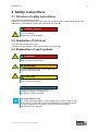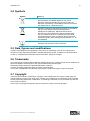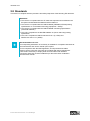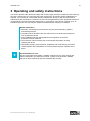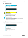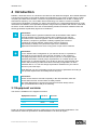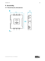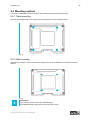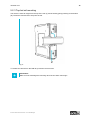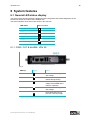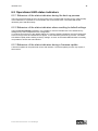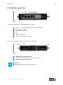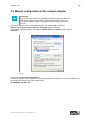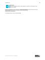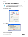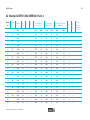
1
Version 2.0 Effective as of 06/15 Translation of original instruction manual User Manual IT Infrastructure IWL3000 series IWL3000 series 2 Index 1 Notes 4 1.1 1.2 1.3 4 4 4 General remark Limitation of liability Relevant device documentation 2 Safety instructions 5 2.1 2.2 2.3 2.4 2.5 2.6 2.7 2.8 Structure of safety instructions Graduation of risk level Explanation of used symbols Symbols Data, figures and modifications Trademarks Copyright Standards 5 5 5 6 6 6 6 7 3 Operating and safety instructions 8 3.1 3.2 3.3 3.4 3.5 3.6 3.7 3.8 3.9 3.10 Safety instructions Operating location Damage due to improper use Warranty / repairs General information on the 5GHz version (802.11 A / 802.11 H) ETSI WLAN information Intended use Improper use Treatment and disposal of lithium batteries Safety instructions 9 9 10 10 10 10 11 11 11 12 4 Introduction 13 3.1 Equipment versions 4.1 Scope of delivery 4.2 Environmental conditions 13 14 15 5 Assembly 16 5.1 Overall device dimensions 5.2 Mounting options 5.2.1 Table mounting 5.2.2 Wall mounting 5.2.3 Top-hat rail mounting 16 17 17 17 18 © ads-tec GmbH • Heinrich-Hertz-Str. 1 • D-72622 Nürtingen IWL3000 series 3 6 System features 19 6.1 General LED status display 6.1.1 PWR / CUT & ALARM / VPN 3G 6.2 Operational LED status indicators 6.2.1 Behaviour of the status indicators during the boot-up process 6.2.2 Behaviour of the status indicators when resetting to default settings 6.2.3 Behaviour of the status indicators during a firmware update 6.3 Interface overview 6.3.1 24 V DC power supply 6.3.2 LAN 1 (RJ45) 6.3.3 LAN 2 (RJ45) 6.3.4 X1 6.3.5 X2 6.3.6 USB CONNECTIONS 6.3.7 SIM CARD READER IN ACCORDANCE WITH ISO 7816 19 19 21 21 21 21 22 23 23 24 25 25 25 26 7 Placing into operation 27 7.1 7.2 7.3 7.4 27 28 30 32 Initial configuration Manual configuration of the network adapter Settings for use with Internet Explorer 8 Calling up the device web interface 8 Certifications 34 8.1 8.2 34 36 Channel list ETSI 2.4 GHz Channel list ETSI 5 GHz, IEEE 802.11 a/h, n 9 Technical details 37 10 Service & support 38 10.1 10.2 38 38 ads-tec support Company address © ads-tec GmbH • Heinrich-Hertz-Str. 1 • D-72622 Nürtingen IWL3000 series 4 1 Notes 1.1 General remark This instruction manual is intended to ensure safe and efficient handling and operation of IT Infrastructure products. The instruction manuals must be read carefully by personnel before commencing any type of work. All of the safety notices and handling instructions given in the manual must be obeyed in order to ensure that work is carried out safely. Operation of the system is subject to the laws and regulations which are applicable in the respective country at national, federal, European and international level. The generally accepted rules of technology, usually in the form of standards, directives, regulations, conditions and technical rules specified by national and federal organisations as well as trade associations and committees for the field of specialisation concerned, shall apply. Figures used in this instruction manual are provided for basic understanding and may differ from the actual design. The operator/operating company is independently responsible for compliance with and observance of any subsequently introduced technical innovations or new legal requirements, as well as for all usual obligations of the operator/operating company. The original version of this instruction manual was written in German. All non-German versions of this instruction manual are translations of the German instruction manual. 1.2 Limitation of liability ads-tec GmbH shall not be liable for personal injury, property damage or damage caused to the product as well as consequential damage that is/was the result of non-compliance with this instruction manual, improper use of the product, repairs and other actions on the product by unqualified specialists and specialists not certified by ads-tec GmbH, or that is/was the result of using unapproved replacement parts. 1.3 Relevant device documentation The following documents are decisive to unit setup and operation: Instruction manual: Contains information for installation, commissioning and operation of the device along with technical data of the device hardware. Website You can download drivers, software, user manuals, leaflets and flyers from the Download section of our website www.ads-tec.de. © ads-tec GmbH • Heinrich-Hertz-Str. 1 • D-72622 Nürtingen IWL3000 series 5 2 Safety instructions 2.1 Structure of safety instructions The signal word classifies the hazard. Reference to the type/consequences and source of the hazard is made underneath the signal word. Instructions for preventing the hazard are identified by an arrow (). SIGNAL WORD Type/consequences of hazard! - Source of hazard Measures to prevent hazard 2.2 Graduation of risk level The signal word classifies the hazard. Instructions for preventing the hazard are identified by an arrow (). 2.3 Explanation of used symbols DANGER Indicates an imminent danger. If not avoided, death or severe injury will result. WARNING Indicates a possible danger. If not avoided, death or severe injury could result. CAUTION Indicates a possible danger. If not avoided, light or minor injuries could result. ATTENTION Indicates a possibly damaging situation. If not avoided, the system or something in its surroundings could be damaged. Recommendation for use: The symbol "Recommendation for use" indicates terms and/or conditions that strictly need to be observed to ensure optimised and/or zero-defect operation. Tips and suggestions for the efficient use of the device and software optimisation are also provided. © ads-tec GmbH • Heinrich-Hertz-Str. 1 • D-72622 Nürtingen IWL3000 series 6 2.4 Symbols Symbol Meaning Designation of batteries in accordance with § 13 of the German Battery Act (BattG). Batteries may not be disposed of with household waste, but must rather be disposed of separately. Used batteries must be returned to the point of sale or a disposal system. Labelling of electrical and electronic devices in accordance with § 7 of the German Electrical and Electronic Equipment Act (ElektroG). Electrical and electronic devices must not be disposed of with household waste, but must rather be taken to a collection point for waste electrical equipment. Such a collection point is generally operated by public waste management authorities, i.e., by municipalities. Symbol for the protective earth connection 2.5 Data, figures and modifications All data, text and figures were prepared to the best of our knowledge. They do not represent any assurance for the properties themselves. Despite taking utmost care, no liability can be assumed for accuracy, completeness and actuality of the information. Subject to changes. 2.6 Trademarks It is noted that any software and/or hardware trademarks and any company brand names mentioned in this documentation are all subject to the general trademark protection rights. StoraXe® and Big-LinX® are registered trademarks of ads-tec. All other third-party trademarks used are hereby acknowledged. In the case of infringement of trademark rights, ads-tec reserves the right to exercise all rights. 2.7 Copyright This instruction manual is protected by copyright. For the authorised user, simple usage rights are granted within the scope of the intent of the contract. Any modified use or exploitation of the provided content, particularly duplication, modification or publishing in whatever form is permitted only with the prior consent of ads-tec. In the case of copyright infringement, ads-tec reserves the right to exercise all rights. © ads-tec GmbH • Heinrich-Hertz-Str. 1 • D-72622 Nürtingen IWL3000 series 7 2.8 Standards This device is compliant with the provisions and safety objectives of the following EU directives: Standards This device is compliant with the CE mark test requirements as defined in the European test standards EN 55022 and EN 61000-6-2 This device is compliant with the DIN EN 60950 (VDE0805, IEC950) testing specifications on “Information technology equipment – Safety" This device is compliant with the DIN EN 60068-2-6 testing specifications (sinusoidal vibration) This unit is compliant to the DIN EN 60068-2-27 (shock and bump) testing specification This unit is compliant to DIN EN 300 328 V1.8.1 (2,4 GHz) and DIN EN 301 893 V1.7.1 (5GHz) Recommendation for use: A corresponding declaration of conformity is available for competent authorities at the manufacturer and can be viewed upon request. For full compliance with the EMC legislation, all components and cables used for device connection must also be compliant with these requirements. It is therefore necessary to employ BUS and LAN cables with shielded connectors and these must be installed as per the instructions contained in the instruction manual. © ads-tec GmbH • Heinrich-Hertz-Str. 1 • D-72622 Nürtingen IWL3000 series 8 3 Operating and safety instructions The device operates under electrical voltage and contains highly sensitive components. Intervention by the user is required only for connecting the power supply lines. Should any further modifications be required, it is necessary to consult either with the manufacturer directly or with service personnel authorised by the manufacturer. The device must be de-energised during work. Appropriate measures must be taken to prevent electrostatic discharges on components. If the device is opened up by an unauthorised person, the user may be subject to hazards and the warranty is invalidated. General information Assembly, commissioning and operation may only be performed by qualified and trained personnel The safety notices and the instruction manual are to be observed by all persons who work with the device At the installation site the valid guidelines and regulations for accident prevention must be observed The instruction manual contains the most important information for safely operating the device Appropriate storage, proper transport, installation and commissioning, as well as careful operation are prerequisites for ensuring safe and proper operation of the device Recommendation for use: Only the original ads-tec firmware / software is allowed for any of the settings and features described in this instruction manual. Loading of any firmware / software that has not been released by ads-tec invalidates the warranty. © ads-tec GmbH • Heinrich-Hertz-Str. 1 • D-72622 Nürtingen IWL3000 series 9 3.1 Safety instructions ATTENTION To prevent damage to the device, all cable lines (power supply, interface cables) must be only be connected while the device is switched off. ATTENTION All installation work performed on the device must be performed only under safe, secure and deenergised conditions. CAUTION Warning - hot surface Protective gloves must be worn when handling devices with ambient temperatures of 50 °C and higher. Disregarding this warning can result in burn injuries or damage to property. Recommendation for use: Always adhere to the safety measures applicable when handling components at risk of being damaged by electrostatic discharges. (DIN EN 61340-5-1 / DIN EN 61340-5-2) 3.2 Operating location This device is designed for industrial use. Make certain that the specified environmental conditions are maintained at all times. Use in non-specified environments, i.e., on board ships, in explosive atmospheres or at extreme elevations, is prohibited. ATTENTION Risk of short circuit! To prevent the formation of water condensate, the device may be turned on only after it has reached the specified ambient temperature. This also applies if the device is exposed to extreme temperature fluctuations. To avoid overheating in operation: The device must not be exposed to direct radiation by sunlight or any other light or heat source. © ads-tec GmbH • Heinrich-Hertz-Str. 1 • D-72622 Nürtingen IWL3000 series 10 3.3 Damage due to improper use Should the control system have evident signs of damages caused, e.g., by improper operation or storage conditions or due to improper use or handling, the device must be shut down immediately. Ensure that it is secured against being started up accidentally. 3.4 Warranty / repairs During the device warranty period, any repairs must only be performed by the manufacturer or by service personnel that has been authorised by the manufacturer. 3.5 General information on the 5GHz version (802.11 A / 802.11 H) ETSI The device is certified for the use of channels of the 5 GHz band according to ETSI EN 301 893 V1.7.1. In this case, the user is to observe the following: Access Point as well as Access Client devices use DFS and TPC by default on all 5 GHz channels, both for indoor as well as outdoor configurations. The devices can therefore always be operated with 23 dBm or 30 dBm maximum transmission power. Information: Access Points must not shut down the DFS outdoors. An Access Client may shut down the DFS. This setting is switched off by default. 802.11a channels cannot be set permanently. Information: The lower four channels (non-DFS) can be set permanently if the DFS is switched off. Switching off the DFS also results in the 60s Scan and Radar Detection functions being switched off, however. Upon activation of the Access Point, the Access Point performs a one-time radar detection scan and then waits for a period of time on an arbitrarily selected channel for a radar pulse before operation on this channel is started. The waiting time depends on the channel and the regulatory domain. If a radar pulse is detected by an Access Client during operation, this is reported to the Access Point according to 8011.h. As a result of this or on account of a detection made on its own, the Access Point changes the channel with a channel switch according to 802.11h. The maximum permissible transmission power varies by channel. It is therefore necessary that the user correctly set the antenna gain if the standard antenna is replaced! 3.6 WLAN information Caution: This information must be observed when operating the devices: •The device does not offer a "secure" transmission medium •The devices do not have a deterministic system behaviour •No MIN/MAX roaming time can be guaranteed The setting of the applicable regulatory authority and the antenna gain is the responsibility of the operating company. © ads-tec GmbH • Heinrich-Hertz-Str. 1 • D-72622 Nürtingen IWL3000 series 11 3.7 Intended use The Industrial Wireless LAN was specifically designed for the IT-Infrastructure of an industrial environment. The following applications are realized by the Industrial Wireless LAN: Remote maintenance, Seamless Roaming, firewall machines, Gigabit Router. Application-specific applications are buildable on various software development kits (SDK). The unit must only be installed and operated within the allowed specifications. The use of an unspecified environment is prohibited. 3.8 Improper use Operation other than or beyond that described for the device shall be deemed improper use. The device is not allowed to be used to control vehicles or for applications for which further approvals beyond the manufacturer's declaration are necessary, e.g. applications with explosion hazard, medical technology, shipping industry. The device must not be put into operation in the case of transport damage or nonconformity with the specifications and, if necessary, must be taken out of operation in the case of changing conditions. In the case of improper use, ads-tec shall not accept responsibility or liability for injury or damage that is directly or indirectly attributable to the handling of the device. Should the device have evident signs of damages caused, e.g., by improper operation or storage conditions or due to improper use or handling, it must be shut down immediately. Ensure that it is secured against being started up accidentally. 3.9 Treatment and disposal of lithium batteries This device contains a lithium battery for supplying the system clock with power as long as the supply voltage is not connected. The battery has a life cycle of 3-5 years depending on which load is applied. ATTENTION Hazard due to thermal loads The more the battery is exposed to higher temperatures, the faster it ages. Avoid thermal loads. WARNING Hazard due to explosion Danger of explosion if using incorrect battery types. Use the battery type recommended by the manufacturer. Lithium batteries should not be exposed to fire, soldered, recharged, opened, short-circuited, reversed or heated above 100 °C and they should be disposed of properly as well as protected against sunlight, moisture and condensation. The battery type to be used is: Lithium battery 1/2AA 3V (e.g. ads-tec part number: DZ-SONS-04100-0) The used lithium battery should be disposed of in accordance with local legal regulations. © ads-tec GmbH • Heinrich-Hertz-Str. 1 • D-72622 Nürtingen IWL3000 series 12 3.10 Safety instructions ATTENTION Damage due to electrostatically sensitive components Damage to the device can be caused by electrostatically sensitive components. All installation and service work performed on the device must be performed only under safe, secure and de-energised conditions. Recommendation for use: Always adhere to the safety measures applicable when handling components at risk of being damaged by electrostatic discharges. The provisions of DIN EN 61340-5-1 / DIN EN 61340-5-2 apply © ads-tec GmbH • Heinrich-Hertz-Str. 1 • D-72622 Nürtingen IWL3000 series 13 4 Introduction Reliable, robust and secure on a wireless LAN: based on the latest technologies, the Industrial Wireless LAN Access Point (IWL) is the network interface for applications in the areas of order picking, mobile computing and data communication. The device supports all standards such as 802.11 a/b/g/n at a transmission frequency of 2.4 and 5 GHz. Robust technology is a matter of course in industrial environments. Regardless of whether you wish to use the device in a refrigerated warehouse or under intensified heat radiation, the expanded temperature range makes it possible. With the MIL certification, the device is also certified with one of the most demanding vibration and shock resistance tests and thereby guarantees a particularly high level of sturdiness. Information: It is possible that the hyperlinks included in this documentation which lead to external websites may no longer function due to updates or they may be accessible under a different hyperlink. ads-tec GmbH (hereafter referred to as "ads-tec") accepts no guarantee or liability regarding the function of hyperlinks to external websites. Furthermore, ads-tec accepts no responsibility or liability of any kind with respect to the installation, application and freedom from errors of any piece of open-source software. Information: For the efficient online configuration of your ads-tec devices, it is possible to download the current version of the free tool "IDA light" on the company's homepage http://www.ads-tec.de. With this tool you can, for example, define individual parameters or whole groups of parameters on a master device and transfer them to a limited selection or to all ads-tec devices of same design and version without having to make these time-consuming configurations on each individual device. You can also assign sequential IP addresses for your ads-tec devices in just a few steps. With IDA light you can comfortably provide own groups of parameters according to your specific requirements and modify them at any time. Information: Unless Access Client is referred to explicitly in the documentation, both IWL Access Point and IWL Access Client are always meant. The used designations of Access Point and Access Client always refer to IWL (Industrial Wireless LAN) in the following. 3.1 Equipment versions The device is available in two equipment versions. Equipment version IWL3210 IWL3220 LAN 1 RJ45 RJ45 LAN 2 RJ45 RJ45 WLAN modules 1 2 RJ45 is an Ethernet standard frequently implemented in telecommunication applications. The transmission method is equivalent to 10/100/1000 Base-T full and half duplex © ads-tec GmbH • Heinrich-Hertz-Str. 1 • D-72622 Nürtingen IWL3000 series 14 4.1 Scope of delivery The contents of the package must be checked for completeness: Scope of delivery IWL3000 series 1 x IWL Access Point and Client 1 x 3-pin connector 2 x 4-pin connector 1 x top-hat rail holder 1 x mounting set with two of each of the following: pan head screw + washer + serrated lock washer 4 x rubber feet 1 x Ethernet cable, 1m red 1 x Quick Start-Up Guide / Quick Assembly Guide 1 x GNU General Public License © ads-tec GmbH • Heinrich-Hertz-Str. 1 • D-72622 Nürtingen IWL3000 series 15 4.2 Environmental conditions The device can be put into operation and used under the following conditions. Failure to observe any one of these conditions will invalidate the warranty. ads-tec cannot be held liable for any damages arising from improper use and handling. Ambient temperature during operation during storage -20 to 70° C -40 to 85° C Humidity during operation during storage 5 to 90%, without condensate 5 to 90%, without condensate Vibration during operation Vibration test: Shock resistance during operation © ads-tec GmbH • Heinrich-Hertz-Str. 1 • D-72622 Nürtingen 1 G, 10 to 500 Hz (DIN EN 60068-2-6) MIL-STD-810F 514.5 C-2 5 to 500 Hz (01-01-2000) 5 G, with a 30 ms half-cycle (DIN EN 60068-2-29) IWL3000 series 5 Assembly 5.1 Overall device dimensions Fig. 1: © ads-tec GmbH • Heinrich-Hertz-Str. 1 • D-72622 Nürtingen 16 IWL3000 series 5.2 Mounting options The device is designed for table mounting, wall mounting and for top-hat rail mounting. 5.2.1 Table mounting Remove the protective foil on the rubber feet and attach them at the marked positions. Fig. 1: 5.2.2 Wall mounting Alternatively, the device can be mounted according to the VESA 75 standard on a suitable mounting surface. Fig. 2: Information: For mounting, use M4 screws of a suitable length. The usable blind hole depth of the mounting holes is 6mm. © ads-tec GmbH • Heinrich-Hertz-Str. 1 • D-72622 Nürtingen 17 IWL3000 series 5.2.3 Top-hat rail mounting The device is set at an angle from the top of the rail. (1) and is fixed by gently pressing on the bottom (2). The device must be felt to snap into the rail. Fig. 3: To release the device from the DIN rail, proceed in reverse order. Information: Make sure not to damage the mounting rail of the unit when removing it.. © ads-tec GmbH • Heinrich-Hertz-Str. 1 • D-72622 Nürtingen 18 IWL3000 series 19 6 System features 6.1 General LED status display The status of the various interfaces is displayed via the integrated LEDs. Status diagnostics of the firewall can thereby be made at the installation site. The status indicators of the device are shown in the overview. LED status Representation Off Green Flashing green Red Orange Flashing orange 6.1.1 PWR / CUT & ALARM / VPN 3G Fig. 4: PWR (1) Signal Action This device is not supplied with voltage Indicates POWER ON, flashes during booting The device is supplied with voltage via POWER and is ready for operation Status (1) This device is not supplied with voltage Error during the boot-up process / recovery image © ads-tec GmbH • Heinrich-Hertz-Str. 1 • D-72622 Nürtingen IWL3000 series 20 Abb. 5: Link (2) / (3) Signal Action There is no Wi-Fi connection active Search for available WLAN networks Connection established Activity (2) / (3) © ads-tec GmbH • Heinrich-Hertz-Str. 1 • D-72622 Nürtingen Active traffic IWL3000 series 21 6.2 Operational LED status indicators 6.2.1 Behaviour of the status indicators during the boot-up process The boot-up process starts as soon as the Access Point is supplied with a power source. With the help of the PWR LED, it is possible to check whether the Access Point boots. The PWR LED should illuminate green and flash slowly. 6.2.2 Behaviour of the status indicators when resetting to default settings Using the Factory Default pushbutton, it is possible to reset the firewall back to the default factory settings at any time, independent of its configuration. To reset the Access Point to the default settings, the Factory Default pushbutton must be pressed prior to the boot-up process and held down for approx. 10 seconds during the boot-up process. The PWR LED flashes rapidly while resetting to factory settings. As soon as the PWR LED illuminates constantly, it is possible to access the web interface. 6.2.3 Behaviour of the status indicators during a firmware update A firmware update can be performed via the web interface. The actual update process may require a few minutes. © ads-tec GmbH • Heinrich-Hertz-Str. 1 • D-72622 Nürtingen IWL3000 series 22 6.3 Interface overview Fig. 6: The device is equipped with the following interfaces (front): 1. 2. 3. 4. 5. 6. 7. Power 24V DC power supply (7…36V) (3-pole plug) LAN1 RJ45 connection LAN2 RJ45 connection X1 X2 USB 2.0 connection WPS pushbutton (factory default) The device is equipped with the following interfaces (rear/side): Fig. 7: 8. WLAN antenna (WLAN module 1) 9. SCM card reader (read in/out the ads-tec SIM cards) 10. WLAN antenna (WLAN module 2) Information: All input voltages can be connected redundantly © ads-tec GmbH • Heinrich-Hertz-Str. 1 • D-72622 Nürtingen IWL3000 series 23 6.3.1 24 V DC power supply This power supply is fed to the device via a lead-through terminal. (The figure shows the socket inside the device) PIN number Signal name 1 24V DC 2 GND 3 PE Technical data of the power adapter • Input voltage: 7 - 36V DC Recommendation for use: The distance between the casing and plug should be at least approx. 30mm amount. Use a flexible cable with a wire cross section of 0.5 mm² / AWG20 and appropriate ferrules to maintain the mechanical force on the connector, as low as possible. 6.3.2 LAN 1 (RJ45) PIN number Signal name 1 TX + 2 TX - 3 RX + 4 NC 5 NC 6 RX - 7 NC 8 NC © ads-tec GmbH • Heinrich-Hertz-Str. 1 • D-72622 Nürtingen IWL3000 series 24 6.3.3 LAN 2 (RJ45) PIN number Signal name 1 TX + 2 TX - 3 RX + 4 NC 5 NC 6 RX - 7 NC 8 NC © ads-tec GmbH • Heinrich-Hertz-Str. 1 • D-72622 Nürtingen IWL3000 series 25 6.3.4 X1 Pin-Nummer Signal-Name 1 24V DC 2 IN (Not Connected) 3 OUT (Wake Up) 4 GND Pin-Nummer Signal-Name 1 24V DC 2 IN 3 OUT 4 GND 6.3.5 X2 6.3.6 USB CONNECTIONS The USB interfaces are used for connecting peripherals with USB connection. The interface complies with the USB 2.0 standard. PIN number Signal name 1 VDC 2 D- 3 D+ 4 GND © ads-tec GmbH • Heinrich-Hertz-Str. 1 • D-72622 Nürtingen IWL3000 series 26 6.3.7 SIM CARD READER IN ACCORDANCE WITH ISO 7816 The SIM card reader is used to store configuration data. PIN number Signal name 1 VCC 5 volt 2 RESET 3 CLOCK 4 NC 5 GND 6 NC 7 I/O 8 NC © ads-tec GmbH • Heinrich-Hertz-Str. 1 • D-72622 Nürtingen IWL3000 series 27 7 Placing into operation 7.1 Initial configuration Caution: The initial configuration of the device can only be performed via the RJ45 interface labelled with LAN. For the initial configuration, a connection to a PC is required. Connecting the 24V DC power source The device can be powered with a 24V DC (3-pole plug) power source. The corresponding plug is included in the scope of delivery of the device. Connect the device with an appropriate power source. Connecting the RJ45 network cable When placing into operation for the first time, a connection is required between the device and a PC via an RJ45 network cable. Connect the device to a PC: Device LAN connection <-> PC LAN connection © ads-tec GmbH • Heinrich-Hertz-Str. 1 • D-72622 Nürtingen IWL3000 series 28 7.2 Manual configuration of the network adapter Information: The procedure described in the following was prepared using the Microsoft Windows XP professional® operating system as an example. If you are using another operating system, the paths and properties described here may vary. Open the properties map for your network adapter. The relative path is as follows: Network connections> LAN connection> Properties (right mouse-key). In the dialogue tab that appears, select option: Internet protocol (TCP/IP) and then click on Properties. Fig. 8: Now select: Use the following IP address Access to the device is only enabled if the following parameters are entered as the fixed IP address or if the computer is located in the same subnet space: IP ADDRESS: 192.168.0.100 © ads-tec GmbH • Heinrich-Hertz-Str. 1 • D-72622 Nürtingen IWL3000 series Information: The last set of digits must be a number between 1 and 253. In the example, "100" has been selected. Once the IP address has been entered, the subnet mask address must be entered. Click on the Subnet mask field and the correct address is entered automatically. Subnet mask: 255.255.255.0 The dialogue tab can now be closed with "OK". © ads-tec GmbH • Heinrich-Hertz-Str. 1 • D-72622 Nürtingen 29 IWL3000 series 30 7.3 Settings for use with Internet Explorer 8 Caution: If Internet Explorer 8 is used, issues with the web interface may occur. If you experience any problems, the IP address of the device must be entered in the local intranet list in order to display the web interface correctly. Open Internet Explorer and navigate to the Security tab under the following path: ToolsInternet optionsSecurity Switch to the Local Intranet icon and click on Sites. Fig. 9: Then click on Advanced. Fig. 10: In the Add this website to the zone address line, enter the device IP address and confirm with Add. Default IP address: http://192.168.0.254 The IP address should now appear in the list under Websites. © ads-tec GmbH • Heinrich-Hertz-Str. 1 • D-72622 Nürtingen IWL3000 series 31 Fig. 11: © ads-tec GmbH • Heinrich-Hertz-Str. 1 • D-72622 Nürtingen IWL3000 series 32 7.4 Calling up the device web interface To access and open the device web interface, start up your web browser. In the browser’s address bar, enter the following IP address and then confirm with Enter: http://192.168.0.254 Login Once the IP address has been entered with success, the login prompt appears. The default settings are to be entered in the login prompt. The default configuration on delivery is: User name : admin Password : admin Confirm your entries by clicking on OK Fig. 12: Information: If the login prompt does not appear, check to ensure that the device has been connected via a RJ45 connection cable. Otherwise, connect the device to a PC (Device LAN connection <> PC LAN connection). If there is still no connection to the firewall login screen, check the proxy and local firewall settings. Often, local subnet addresses (e.g. 192.168.x.x) are also diverted to a proxy server. In this case, it is possible to select the "Bypass proxy server for local addresses" option to enter the address in question. © ads-tec GmbH • Heinrich-Hertz-Str. 1 • D-72622 Nürtingen IWL3000 series 33 The device web interface then appears. Fig. 13: © ads-tec GmbH • Heinrich-Hertz-Str. 1 • D-72622 Nürtingen IWL3000 series 34 8 Certifications 8.1 Channel list ETSI 2.4 GHz Countries Frequency TPC GHz Transmitting power Access Point Transmitting power Access Client [mW] [dBm] [mW] [dBm] Indoor Outdoor Channel can be set permanently (AP & AC) 01 2.412 X 100 20 100 20 X X X 02 2.417 X 100 20 100 20 X X X 03 2.422 X 100 20 100 20 X X X 04 2.427 X 100 20 100 20 X X X 05 2.432 X 100 20 100 20 X X X 06 2.437 X 100 20 100 20 X X X 07 2.442 X 100 20 100 20 X X X 08 2.447 X 100 20 100 20 X X X 09 2.452 X 100 20 100 20 X X X 10 2.457 X 100 20 100 20 X X X 11 2.462 X 100 20 100 20 X X X 12 2.467 X 100 20 100 20 X X X 13 2.472 X 100 20 100 20 X X X Information: TPC can optionally be activated at 2.4 GHz 13 channels, each 22 MHz wide 2 to 3 interference free channels in 802.11n operation with 40MHz channel bandwidth © ads-tec GmbH • Heinrich-Hertz-Str. 1 • D-72622 Nürtingen IWL3000 series Achtung: TPC is always active at 5 GHz 19 channels, each 22 MHz wide © ads-tec GmbH • Heinrich-Hertz-Str. 1 • D-72622 Nürtingen 35 IWL3000 series 36 8.2 Channel list ETSI 5 GHz, IEEE 802.11 a/h, n [GHz] [sek] [mW] [dBm] [mW] [dBm] [mW] [dBm] 5,180 0 200 23 200 23 200 23 x x 5,200 0 200 23 200 23 200 23 x x 5,220 0 200 23 200 23 200 23 x x 5,240 0 200 23 200 23 200 23 x x 5,260 60 x x 200 23 200 23 200 23 x 5,280 60 x x 200 23 200 23 200 23 x 5,300 60 x x 200 23 200 23 200 23 x 5,320 60 x x 200 23 200 23 200 23 x 5,500 60 x x 1.000 30 1.000 30 200 23 x x 5,520 60 x x 1.000 30 1.000 30 200 23 x x 5,540 60 x x 1.000 30 1.000 30 200 23 x x 5,560 60 x x 1.000 30 1.000 30 200 23 x x 5,580 60 x x 1.000 30 1.000 30 200 23 x x 5,600 600 x x 1.000 30 1.000 30 200 23 x x 5,620 600 x x 1.000 30 1.000 30 200 23 x x 5,640 600 x x 1.000 30 1.000 30 200 23 x x 5,660 60 x x 1.000 30 1.000 30 200 23 x x 136 5,680 60 x x 1.000 30 1.000 30 200 23 x x 140 5,700 60 x x 1.000 30 1.000 30 200 23 x x 40 44 44+ 48 52 52+ 56 60 60+ 64 100 100+ 104 108 108+ 112 116 116+ 120 124 124+ 128 132 132+ © ads-tec GmbH • Heinrich-Hertz-Str. 1 • D-72622 Nürtingen Transmitting power Client without DFS Indoor CAC time 36+ Transmitting power Client with DFS Channel can be set permanently (only AP) Frequency 36 Transmitting power Access Point Outdoor n TPC Channel a/h DFS Channel 9 Technical details Device data IWL3000 series Operating system Embedded LinuX Configuration protocol http, https Power supply 24V DC +/- 20%, redundant voltage input Interfaces IN/OUT (electrically isolated) 1 x LAN RJ45 connection 10/100/1000MBit/s Auto crossover 1 x LAN RJ45 connection 10/100/1000MBit/s Auto crossover External device dimensions 135 mm x 159 mm x 35 mm Weight approx. 1 kg Protection class IP20 Max. current consumption max. 600 mA at 24V DC Ambient temperature during operation from 20°C to + 70° during storage from -25°C to + 85°C Information: Detailed information about the device can be found on our website: http://www.ads-tec.de. IWL3000 series 38 10 Service & support ads-tec and its partner companies offer you comprehensive maintenance and support services, ensuring quick and competent support should you have any questions or concerns with regard to ads-tec products and equipment. Because ads-tec products are also used by partner companies, these devices may have customised configurations. Should any questions arise with regard to these specific configurations and software installations, please contact them as ads-tec will not be able to answer such questions. ads-tec does not provide support services for any device that was not purchased directly from ads-tec. In this case, maintenance and support is provided by the partner company. 10.1 ads-tec support The ads-tec support team is available for inquiries from direct customers between 8:30am and 5:00pm, Monday to Friday. The support team can be reached via phone, fax or e-mail: Phone: +49 7022 2522-202 Fax: +49 7022 2522-2602 Email: [email protected] 10.2 Company address ads-tec GmbH Heinrich-Hertz-Str.1 72622 Nürtingen Germany Phone: Fax: Email: Web: +49 7022 2522-0 +49 7022 2522-400 [email protected] www.ads-tec.de © ads-tec GmbH • Heinrich-Hertz-Str. 1 • D-72622 Nürtingen