1
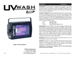
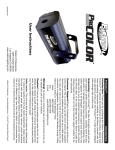
DM-2512R
USER MANUAL
PUSH
1
2
1
2
2
1
3
3
Power
A
3
DMX IN
B
DMX OUT
Introduction
Thank you for purchasing the Elation DM-2512R. Please read the instructions in this manual
carefully and thoroughly before attempting to operate this unit. These instructions contain important
information regarding safety during use and maintenance. Please fill out and return the enclosed
warranty card to validate your purchase.
Customer Service
Elation provides a toll free customer support line, to provide set up help and to answer any question should
you encounter problems during your set up or initial operation. You may also visit us on the web at
www.elationlighting.com for any comments or suggestions.
All returned service items whether under warranty or not, must be freight pre-paid and accompany a
Return Authorization (RA) number. The RA number must be clearly written on the outside of the return
package. Items returned without a RA number clearly marked on the outside of the package will be refused
and returned at customer’s expense. You may obtain a RA number by contacting customer service.
A brief description of the problem as well as the RA number must be written down on a piece of paper and
included in the shipping container. If the unit is under warranty, you must also provide a copy of your proof
of purchase invoice.
Customer Service hours are Monday through Friday 8:00 a.m. - 5:00 p.m. Pacific Standard Time.
Toll Free: (866) 245-6726
Phone: (323) 582-3322
Fax: (323) 832-9142
Information: [email protected]
Sales: [email protected]
Support: [email protected]
Forum: forums.elationlighting.com/eve
This manual is Copyright © 2008 Elation Professional. All rights reserved. No part of
the manual included with this product can be reproduced or transmitted in any form, by
any means, for any purpose without prior written authorized permission.
Information contained in this manual is subject to change at any time and without notice.
Please contact Elation Customer Service or visit www.elationlighting.com for the latest
manual revisions.
24-004-1291
Rev 1.2
2-Year Limited Warranty
Elation® hereby warrants, to the original purchaser, Elation Professional® products to be free of
manufacturing defects in material and workmanship for a period of 2 Years (730 days) on all internal
parts and components and 1 Year (365 days) on labor from the date of purchase. This warranty shall
be valid only if the product is purchased within the United States of America, including possessions
and territories. It is the owner’s responsibility to establish the date and place of purchase by
acceptable evidence, at the time service is sought.
For warranty service, send the product only to the Elation factory. All shipping charges must be prepaid.
If the requested repairs or service (including parts replacement) are within the terms of this
warranty, Elation will pay return shipping charges only to a designated point within the United States
except Hawaii or Alaska. If the entire instrument is sent, it must be shipped in its original package.
No accessories should be shipped with the product. If any accessories are shipped with the product,
Elation shall have no liability whatsoever for loss of or damage to any such accessories, nor for the
safe return thereof.
This warranty is void if:
• The serial number has been altered or removed
• The product is modified in any manner which Elation concludes, after inspection, affects the
reliability of the product
• The product has been repaired or serviced by anyone other than the Elation factory unless
prior written authorization was issued to purchaser by Elation
• The product is damaged because not properly maintained as set forth in the instruction
Manual
This is not a service contract, and this warranty does not include maintenance, cleaning or periodic
check-up. During the period specified above, Elation will replace defective parts at its expense, and
will absorb all expenses for warranty service and repair labor by reason of defects in material or
workmanship. The sole responsibility of Elation under this warranty shall be limited to the repair of
the product, or replacement thereof, including parts, at the sole discretion of Elation. All products
covered by this warranty were manufactured after January 1, 1990, and bear identifying marks to that
effect.
Elation reserves the right to make changes in design and/or improvements upon its products without
any obligation to include these changes in any products theretofore manufactured.
No warranty, whether expressed or implied, is given or made with respect to any accessory supplied
with products described above. Except to the extent prohibited by applicable law, all implied
warranties made by Elation in connection with this product, including warranties of merchantability or
fitness, are limited in duration to the warranty period set forth above. And no warranties, whether
expressed or implied, including warranties of merchantability or fitness, shall apply to this product
after said period has expired. The consumer’s and or Dealer’s sole remedy shall be such repair or
replacement as is expressly provided above; and under no circumstances shall Elation be liable for any
loss or damage, direct or consequential, arising out of the use of, or inability to use, this product.
This warranty is the only written warranty applicable to Elation Products and supersedes all prior
Safety
The following safety information relates to the DM-2512R. Please read each item carefully to ensure you
fully understand them.
To prevent the risk of electrical shock, do not open this unit. There are no user serviceable parts inside
this unit. Do not attempt any repairs yourself. Doing so will void your manufactures warranty. Should your
unit require service, please contact your nearest Elation dealer or Elation Customer Service.
To prevent or reduce the risk of electrical shock or fire, do not expose this unit to rain or moisture. Do not
remove the plug ground pin or connect to an ungrounded circuit.
This unit is not designed for use by persons under the age of 12. Use only under adult supervision.
Turn off the power if not using this unit for a long time.
Description
The DM-2512R merges two DMX signal inputs, to one output. Three operation modes can be selected by
using the 2 dip switch setting. The three operation modes include HTP (Highest Takes Priority) mode,
Backup mode and Merge mode. When set to HTP mode, the controller with the highest channel output
setting will take priority on output. HTP is most commonly used to controller dimmer channels. When set to
Backup, a controller that is connected to the B input is on stand and will only take precedence if the
controller connected to the A input fails. When set to Merge mode, controller signals coming int o input A
& B will merge to one output. 10-position dip switches are available so the starting DMX address channel
can be set for the controller that is connected to input B. For example, a Stage Desk 16 is connected to
input A, we would patch the controller that is connected to input B at channel 17 and also set the binary
address on the DM-2512R to 17.
HTP Mode
1 2
Set dip-switch 1 and 2 to "Off" position. This unit will be in HTP (High Take Priority) mode. When two DMX
signals are present, the higher DMX values for each channel (1-512) will take precedence. This may allow
for some channels of input A controller to be active and other channels from input B controller to be active.
BACKUP Mode
1 2
Set dip-switch 1 to "On" and 2 to "Off" position. This unit will be in BACKUP mode. When DMX signal A is
present. it will take DMX output priority. When DMX signal A is lost, DMX signal B will takes DMX output
priority.
MERGE Mode
1 2
Set dip-switch 1 to "Off" and 2 to "On" position. This unit will be in MERGE mode. You can merge DMX
signals A and B into a one DMX output. You must set the starting DMX address for the controller that is
connected to Input B with dip switches 1-9.
Note : If you set dip-switch 1 to "On" and the others to "Off" position, all DMX channel output will start
with the 1st channel of DMX signal B.
Here is a DMX Address setting diagram and a DMX Address table for reference.
DMX Address Table
DMX Address Setting
Dip-switch #
1
2
3
4
5
6
7
8
9
on
off
10
DMX B
START
CH#
(2)
(4)
(8)
(16)
(32)
(64)
(128)
(256)
DMX B
START
CH#
DIP-SWITCHS
ON
1
1
11
1, 2, 4
2
2
1, 2
12
3, 4
1, 3, 4
4
3
14
2, 3, 4
5
1, 3
15
1, 2, 3, 4
6
2, 3
16
5
7
1, 2, 3
:
:
8
9
4
1, 4
:
:
:
:
10
2, 4
511
1,2,3,4,5,6,7,8,9
3
(1)
DIP-SWITCHS
ON
13
Operation Guide
1. With the DM-2512R’s power switch OFF, connect data cables coming out of your lighting control devices
into the male, DMX Inputs, of the DM-2512R. Connect data cable to the output of DM-2512 and into first DMX
device in line.
2.
Turn the power switch ON. Indicator LED should illuminate.
3. When signal is present to inputs A & B, DMX indicator’s should illuminate for both.
4. Set your desired function mode.
1 2
MODE
HTP
Backup
Merge
Technical Specifications
Power Requirement: DC 9V, 1000mA Min.( AC/DC adaptor included)
DMX Input:
DMX output:
Two 3 pin XLR male sockets on the front panel
(Two 3 pin XLR male sockets on the rear panel )
Two 3 pin XLR female sockets on the front panel
(One 3 pin XLR female sockets on the rear panel )
Dimension:
482 x 73 x 44mm
Weight:
1.15 kg