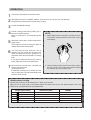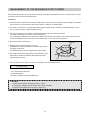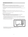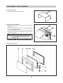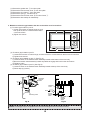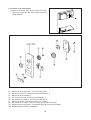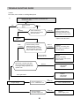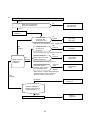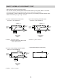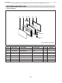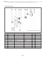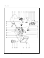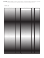
1
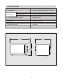
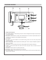
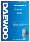
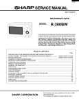
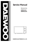
Service Manual
Microwave Oven
Model: KOR-61052S
✔ Caution
: In this Manual, some parts can be changed for improving, their
performance without notice in the parts list. So, if you need the
latest parts information,please refer to PPL(Parts Price List) in
Service Information Center (http://svc.dwe.co.kr).
DAEWOO ELECTRONICS CO., LTD.
PRECAUTIONS TO BE OBSERVED BEFORE AND
DURING SERVICING TO AVOID POSSIBLE
EXPOSURE TO EXCESSIVE MICROWAVE ENERGY
(a) Do not operate or allow the oven to be operated with the door open.
(b) Make the following safety checks on all ovens to be serviced before activating the magnetron
or other microwave source, and make repairs as necessary: (1) Interlock operation, (2) proper
door closing, (3) seal and sealing surfaces (arcing, wear, and other damage), (4) damage to or
loosening of hinges and latches, (5) evidence of dropping or abuse.
(c) Before turning on microwave power for any service test or inspection within the microwave
generating compartments, check the magnetron, wave guide or transmission line, and cavity
for proper alignment, integrity, and connection.
(d) Any defective or misadjusted components in the interlock, monitor, door seal, and microwave
generation and transmission systems shall be repaired, replaced, or adjusted by procedures
described in this manual before the oven is released to the owner.
(e) A microwave leakage check to verify compliance with the Federal Performance Standard
should be performed on each oven prior to release to the owner.
TABLE OF CONTENTS
PROPER USE AND SERVICE PRECAUTIONS . . . . . . . . . . . . . . . . . . . . . . . . . . . . . . . . . . . . . . . . . . . . . . . . . . . . . . . . . . . . . .3
SPECIFICATIONS . . . . . . . . . . . . . . . . . . . . . . . . . . . . . . . . . . . . . . . . . . . . . . . . . . . . . . . . . . . . . . . . . . . . . . . . . . . . . . . . . . . . . . . . . . .4
FEATURE DIAGRAM . . . . . . . . . . . . . . . . . . . . . . . . . . . . . . . . . . . . . . . . . . . . . . . . . . . . . . . . . . . . . . . . . . . . . . . . . . . . . . . . . . . . . . . .5
INSTALLATION . . . . . . . . . . . . . . . . . . . . . . . . . . . . . . . . . . . . . . . . . . . . . . . . . . . . . . . . . . . . . . . . . . . . . . . . . . . . . . . . . . . . . . . . . . . . .6
OPERATION . . . . . . . . . . . . . . . . . . . . . . . . . . . . . . . . . . . . . . . . . . . . . . . . . . . . . . . . . . . . . . . . . . . . . . . . . . . . . . . . . . . . . . . . . . . . . . . .7
MEASUREMENT OF THE MICROWAVE OUTPUT POWER . . . . . . . . . . . . . . . . . . . . . . . . . . . . . . . . . . . . . . . . . . . . . . . . . .8
MICROWAVE RADIATION TEST . . . . . . . . . . . . . . . . . . . . . . . . . . . . . . . . . . . . . . . . . . . . . . . . . . . . . . . . . . . . . . . . . . . . . . . . . . . .9
WIRING DIAGRAM . . . . . . . . . . . . . . . . . . . . . . . . . . . . . . . . . . . . . . . . . . . . . . . . . . . . . . . . . . . . . . . . . . . . . . . . . . . . . . . . . . . . . . . . .10
CIRCUIT DESCRIPTION . . . . . . . . . . . . . . . . . . . . . . . . . . . . . . . . . . . . . . . . . . . . . . . . . . . . . . . . . . . . . . . . . . . . . . . . . . . . . . . . . . .11
PRECAUTIONS FOR DISASSEMBLY AND REPAIR . . . . . . . . . . . . . . . . . . . . . . . . . . . . . . . . . . . . . . . . . . . . . . . . . . . . . . . .13
DISASSEMBLY AND ASSEMBLY . . . . . . . . . . . . . . . . . . . . . . . . . . . . . . . . . . . . . . . . . . . . . . . . . . . . . . . . . . . . . . . . . . . . . . . . . .14
INTERLOCK MECHANISM . . . . . . . . . . . . . . . . . . . . . . . . . . . . . . . . . . . . . . . . . . . . . . . . . . . . . . . . . . . . . . . . . . . . . . . . . . . . . . . . 19
TROUBLE SHOOTING GUIDE . . . . . . . . . . . . . . . . . . . . . . . . . . . . . . . . . . . . . . . . . . . . . . . . . . . . . . . . . . . . . . . . . . . . . . . . . . . . .21
COMPONENT TEST PORCEDURE . . . . . . . . . . . . . . . . . . . . . . . . . . . . . . . . . . . . . . . . . . . . . . . . . . . . . . . . . . . . . . . . . . . . . . . .23
SAFETY INTERLOCK CONTINUITY TEST . . . . . . . . . . . . . . . . . . . . . . . . . . . . . . . . . . . . . . . . . . . . . . . . . . . . . . . . . . . . . . . . . .24
EXPLODED AND PARTS LIST . . . . . . . . . . . . . . . . . . . . . . . . . . . . . . . . . . . . . . . . . . . . . . . . . . . . . . . . . . . . . . . . . . . . . . . . . . . . .25
2
CAUTION : This Device is to be Serviced Only by Porperly Qualified Service Personnel. Consult the
Service Manual for Proper Service Procedures to Assure Continued Compliance with the
Federal Performance Standard for Microwave Ovens and for Precautions to be Taken to
Avoid Possible Exposure to Excessive Microwave Energy.
PROPER USE AND SERVICE PRECAUTIONS
1. For Safe Operation
Damage that allows the microwave energy (that cooks or heats the food) to escape will result in poor cooking
and may cause serious bodily injury to the operator.
IF ANY OF THE FOLLOWING CONDITIONS EXIST, OPERATOR MUST NOT USE THE APPLIANCE.
(Only a trained service personnel should make repairs.)
1)
2)
3)
4)
5)
A broken door hinge.
A broken door viewing screen.
A broken front panel, oven cavity.
A loosened door lock.
A broken door lock.
The door seal area and oven cavity surface be kept clean.
No grease, soil or spatter should be allowed to build up on these surfaces or inside the oven.
DO NOT ATTEMPT TO OPERATE THIS APPLIANCE WITH THE DOOR OPEN. The microwave oven has
concealed switches to make sure the power is turned off when the door is opened. Do not attempt to defeat
them.
DO NOT ATTEMPT TO SERVICE THIS APPLIANCE UNTIL YOU HAVE READ THIS SERVICE MANUAL.
2. For Safe Service Procedures.
1) If the oven is operative prior to servicing, a microwave emission check should be performed prior to servicing
the oven.
2) If any ascertained oven unit is found to have excessive emission level 5mW/cm2, the service person should:
(a) inform the manufacturer, importer or assembler,
(b) repair the unit at no cost to the owner,
(c) attempt to ascertain the cause of the excessive leakage,
(d) tell the owner of the unit not to use the unit until the oven has been brought into compliance.
3) If the oven operates with the door open, the service person should tell the user not to operate the oven and
contact the manufacturer immediately.
CAUTION
MICROWAVE RADIATION
PERSONNEL SHOULD NOT BE EXPOSED TO THE MICROWAVE ENERGY WHICH MAY RADIATE
FROM THE MAGNETRON OR OTHER MICROWAVE GENERATING DEVICE IF IT IS IMPROPERLY
USED OR CONNECTED. ALL INPUT AND OUTPUT MICROWAVE CONNECTIONS, WAVEGUIDES,
FLANGES, AND GASKETS MUST BE SECURE. NEVER OPERATE THE DEVICE WITHOUT A
MICROWAVE ENERGY ABSORBING LOAD ATTACHED. NEVER LOOK INTO AN OPEN
WAVEGUIDE OR ANTENNA WHILE THE DEVICE IS ENERGIZED.
3
SPECIFICATIONS
Item
Specification
POWER SUPPLY
MICROWAVE
230V~50HZ, SINGLE PHASE WITH EARTHING
POWER CONSUMPTION
1200 W
OUTPUT POWER
800 W (IEC 705) (FULL MICROWAVE POWER)
FREQUENCY
2450 MHz
OUTSIDE DIMENSIONS (WXHXD)
465X274X360 mm
CAVITY DIMENSIONS (WXHXD)
290X200X294 mm
NET WEIGHT
APPROX. 13.5 Kg
TIMER
35 min. DUAL SPEED
POWER SELECTIONS
5 LEVELS
CAVITY VOLUME
0.6 Cu. Ft
* Specifications subject to change without notice.
465
274
D
4
FEATURES DIAGRAM
2
4
1
9
12
11
8
3
5
6
7
1 Saftey Interlock System.
2 Door Viewing Screen - Allows viewing of food, the screen is designed so that light can pass through,
but not the microwave.
3 Door Hook - When the door is closed, it will automatically shut. If the door is opened while the oven
is operating, the magnetron will immediately stop operating.
4 Oven Cavity
5 Door Seal - Door seal maintains the microwave energy within the oven cavity and prevents
microwave leakage.
6 Glass Cooking Tray - Made of special heat resistant glass. Food in a proper receptacle is placed on
this tray for cooking.
7 Roller guide - This must always be used for cooking together with the glass cooking tray.
8 Coupler - this fits over the shaft in the center of the oven’s cavity floor. This is to remain in the oven
for all cooking.
9 Knob V.P.C - Used to select a microwave power level.
0 Knob timer - Used in setting cooking time for all functions.
q Door Release button - By pushing this button the latch system cut off all circuits and stops the oven
before the door is opened.
5
INSTALLATION
1. Steady, flat location.
This microwave oven should be set on a steady, flat surface.
2. Leave space behind and side.
All air vents should be kept a clearance. If all vents are covered during operation, the oven may overheat and,
eventually, cause oven failure.
3. Away from radio, and TV sets
Poor television reception and radio interference may result if the oven is located close to a TV, Radio, or
antenna, feeder and so on.
4. Away from heating appliances and water taps
Keep the oven away from hot air, steam or splash when choosing a place to position it, or the insulation might
be adversely affected and breakdowns occur.
5. Power supply
• Check your local power source.
This microwave oven requires a current of approximately 6 amperes, 230V 50Hz.
Use a receptacle that will accept the earth prong.
• Voltage Warning
The voltage used must be the same as specified on this Microwave Oven.
Using a higher voltage may result in a fire or other accident causing oven damage. Using low voltage will
cause slow cooking.
We are not responsible for damage resulting from use of this Microwave Oven will a voltage or amperage
fuse other than those specified.
• Power supply cord is about 1.0 meters long. Do not use an extension cord.
If the supply cord is damaged, it must be replaced by the manufacturer or its service agent or a similarly
qualified person in order to avoid a hazard;
CAUTION : Do not under any circumstances cut or remove the round earthing prog from this pulg.
CAUTION : Maintenances works like the replacing of the power cable must be made by a technician
qualified of the after-sales-services.
WARNING : This appliance must be earthed.
IMPORTANT
This wires in this mains lead are coloured inaccordance with the following code.
Green-and-yellow
: Earth
Blue
: Neutral
Brown
: Live
As the colours of the wires in the mains lead of this appliance may not correspond with the coloured
markings identifying the terminals in your plug, proceed as follows:
The wire which is coloured green-and-yellow must be connected to the terminal in the plug which is marked
with the letter ‘E’ or by the earth symbol or green-and-yellow.
The wire which is coloured blue must be connected to the terminal which is marked with the letter ‘N’ or
coloured black.
The wire which is coloured brown must be connected to the terminal which is marked with the letter ‘L’ or
coloured red.
6. Examine the oven after unpacking for any damage such as:
Dents, A misaligned door, Broken door, A dents in cavity.
If any of the above are visable, do not install this oven.
6
OPERATION
1
2
3
4
5
Connect the main lead to an electrical outlet.
After placing the food in a suitable container, open the oven door and put it on the glass tray.
The glass tray must always be in place during cooking.
CLOSE THE DOOR securely.
Choose cooking power level by setting V.P.C.
knob to the desired position.
Refer to cookbook for recommended power
levles.
NOTE :
1. When setting Timer for less than 2 minutes, turn the
Timer past 2 minutes and then return to the correct
timer setting.
Determine cooking time. Consult cookbook for
recipe timing.
Oven light turns on and cooling fan starts to
operate. Microwave cooking starts.
0
•
2
3
35
30
6
7
•
4
25
You may open the door while the oven is
operating. As soon as the door is opened, the
safety mechanisms stop the generation of
microwave power and the operation of cooking
timer.
If you wish to change the time during cooking,
simply adjust the Timer to the desired time.
When the timer reaches zero, a bell will ring
and the unit will turns off.
Oven light turns off.
If additional cooking time is needed and the
door is closed, the oven will automatically start
when the Timer is reset.
1
5
20
6
15
10
2. Various clicking noises may be heard when turning
the V.P.C. Knob. This is normal and does not affect
the operation of your microwave oven.
Variable power cooking
ON and OFF cycle time of mechanicial V.P.C. switch is 30 seconds.
When the V.P.C. knob is set to the desired position and timer knob turns to the desired position, the V.P.C
switch has a cycle (ON/OFF time (sec)) listed below.
Variable power setting
(HIGH)
(MED HIGH)
(MEDIUM)
(DEFROST)
(WARM)
ON/OFF time (SEC)
30/0
23.2/6.8
16.5/13.5
9.8/20.2
5/25
7
POWER
100%
77%
55%
33%
17%
MEASUREMENT OF THE MICROWAVE OUTPUT POWER
Microwave output power can be checked by indirectly measuring the temperature rise of a certain amount of water
exposed to the microwave as directed below.
Procedure
1. Microwave power output measurement is made with the microwave oven supplied at rated voltage and operated
at its maximum microwave power setting with a load of 1,000±5cc of potable water.
2. The water is contained in a cylindrical borosilicate glass vessel having a maximum material thickness of 3 mm
and an outside diameter of approximately 190 mm.
3. The oven and the empty vessel are at ambient temperature prior to the start of the test.
The initial temperature of the water is 10±2˚C(50±3.6˚F).
It is measured immediately before the water is added to the vessel. After addition of the water to the vessel, the
load is immediately placed on the center of the shelf which is in the lowest normal position.
4. Microwave power is switched on.
Water Load
5. Heating time should be exactly 52 seconds.
Heating time is measured while the microwave generator is
operating at full power.
The filament heat-up time for magnetrons is not included.
6. The initial and final water temperatures are selected so that
the maximum defference between the ambient and final
water temperature is 5K.
Tray
7. The microwave power output P in watts is calculated from the following formula:
P = 4187 X ∆ T/t
• ∆ T is actual temperature rise.
• t is the heating time.
The power measured should be 800W±10%.
CAUTION :
1. Water load should be measured exactly to 1 liters.
2. Input power voltage should be exactly 230 volts as specified.
3. Ambient temperature should be 20±2˚C (68±3.6˚F)
8
MICROWAVE RADIATION TEST
WARNING
• Make sure to check the microwave leakage before and after repair or adjustment.
• Always, start measuring of an unknown field to assure safety for operating personnel from microwave energy.
• Do not place your hands into any suspected microwave radiation field unless the safe density level is known.
• Care should be taken not to place the eyes in direct line with the source of microwave energy.
• Slowly approach the unit under test until the radiometer reads an appreciable microwave leakage from the unit
under the test.
Procedure
A) Prepare Microwave Energy Survey Meter, 600cc glass beaker, glass thermometer 100˚C or 212˚F.
B) Pour 275cc±15cc of tap water initially at 20±5˚C(68±9˚F) in the 600cc beaker with an inside diameter of approx.
9.5cm (3.5 in).
C) Place it at the center of the tray and set it in a cavity.
D) Close the door and operate the oven.
E) Measure the leakage by using microwave energy survery meter with dual ranges, set to 2450 MHz.
- Measured radiation leakage must not exceed the values prescribed below.
• Leakage for a fully assembled oven with door normally closed must be less than 4mW/cm2.
- When measuring the leakage, always use the 2 in (5cm) space cone with probe. Hold the probe perpendicular
to the cabinet, door. Place the space cone of the probe on the door, cabinet, door seam, door viewing screen,
the exhaust air vents and the suction air vents.
- Measuring should be in a counter-clockwise direction at a rate of 1 inch/sec. If the leakage of the cabinet door
seam is unkow, move the probe more slowly.
- When measuring near a corner of the door, keep the probe perpendicular to the areas making sure the probe
end at the base of the cone does not get closer than 2 inches from any metal.
If it does, erroneous reading may result.
9
WIRING DIAGRAM(SLOW ACTING RELAY TYPE)
10
WIRING DIAGRAM
10-1
CIRCUIT DESCRIPTION
1. When the food is placed in the oven cavity and door is closed.
• The contact of the interlock monitor switch open (NO).
• The contacts of the primary interlock switch and secondary interlock switch close.
12A Fuse
Primary
Interlock
Switch
Timer
Switch
NO
COM
Interlock
Monitor
Switch
NC
TM
CL
GM
FM
Secondary
Interlock
Switch
TM Timer Motor
CL Cavity Lamp
GM Geared Motor FM
Fan Motor
Fig. 1
2. When the timer is set to the time desired.
• The contact of the timer switch close.
• Oven lamp turn on.
• 230V AC is applied to the high voltage transformer.
• Turntable motor start rotating and glass tray rotating.
• Fan motor rotating and cools the magnetron by blowing air.
• Timer motor operating and point to passing cooking time.
• 3.3 Volts AC is generated from the filamente winding of the high voltage transformer. This filament voltage is
applied to the magnetron to heat the magnetron filament through two noise preventing choke coils.
• A high voltage of 2000 Volts AC is generated in the secondary of high voltae transformer and this secondary
voltage is increased by the action of the diode and the charging of the high voltage capacitor. This resultant
D.C voltage is then applied to the anode of the magnetron. As shown in Fig. 2 the first half cycle of the high
voltage produces in the high voltage transformer secondary charges the high voltage capacitor. Current flow is
in the direction of the dotted-line during the second half cycle, the voltage produced by the transformer
secondary, and the charge of the high voltage capacitor are combined and applied to the magnetron as shown
by the solid line so that oscillations begins.
The disturbance wave generated by the magnetron is prevented by the choke coils of 1.5µH, filter capacitors of
500pF and the magnetron’s shielded case so that TV and radio programs are not impired by noise.
11
HIGH VOLTAGE
TRANSFORMER
RD
H.V
FUSE
RD
H.V.
CAPACITOR
MAGNETRON
H.V. DIODE
Fig.2
3. When the door is opened during cooking.
• Primary interlock switch and secondary interlock switch open to cut off the primary voltage to the high voltage
transformer to stop microwave oscillation.
• Fan motor, timer motor and turntable motor stop rotating.
• Oven lamp turn off.
• As soon as the door is opened, monitor switch close(NC) to create the short circuit.
If the contacts of primary interlock switch and secondary interlock switch are both malfunction, the 12A fuse
blows open due to the large current surge caused by monitor switch activation.
12
PRECAUTIONS FOR DISASSEMBLY AND REPAIR
– Cautions to be observed when trouble shooting.
Unlike many other appliances, the microwave oven is a high-voltage, high-current equipment. It is completely
safety during normal operation. However, carelessness in servicing the oven can result in an electric shock or
possible danger from a short circuit.
You are asked to observe the following precautions carefully.
(1) Always remove the power plug from the outlet before servicing.
(2) Use an insulated screwdriver and ware rubber gloves when servicing the high voltage side.
(3) Discharge the high voltage capacitor before touching any oven components or wiring.
1. Check the earthed.
Do not operate on a two wire extension cord. The
microwave oven is designed to be used with earthed.
It is imperative, therefore, to makes sure it is earthed
properly before begining repair work.
2. Warning about the electric charge in the high
voltage capacitor.
For about 30 seconds after the operation stopped, and
electric charge remains in the high voltage capacitor.
When replacing or checking parts, short between oven
chassis and the negative high terminal of the high
voltage capacitor, by using a properly insulted screw
driver to discharge.
(4) When the 12A fuse is blown out due to the operation of the monitor switch; replace primary, secondary
interlock switch and monitor switch.
Refer to next page for the necessary adjustment.
(5) After repair or replacement of parts, make sure that the screws are properly tightened, and all electrical
connections are tightened.
(6) Do not operate without cabinet.
CAUTION : Service personnel should remove their watches whenever working close to or repairing the
magnetron.
WARNING : When servicing the appliance, need a care of touching or replacing high potential parts
because of electrical shock or exposing microwave. These parts are as follows-H.V.
Transformer, Magnetron, H.V. Capacitor, H.V. Diode.
13
DISASSEMBLY AND ASSEMBLY
1. To remove cabinet.
Remove three screws on cabinet back.
2. To remove door assembly.
1) Remove two screws 1 which secure the stopper
hinge top.12
2) Remove the stopper hinge top 2 and door assembly
3 from top plate of cavity.
3) Remove the stopper hinge top 2 from door assembly.
4) Reverse the above for reassembly taking care to
replace fixing glue.
NOTE : After replacing the door preform a check
1
3
2
of correct alignment with the hinge and
cavity front face.
3. To remove door parts.
14
(1) Remove the gasket door 1 from door plate.
(2) Remove the barrier screen inner 2 from door plate.
(3) Remove the door frame 3 from door plate.
(4) Remove the spring 6 and the hook 4.
(5) Remove the barrier screen outer 6 from door frame 3.
(6) Reverse the above steps for reassembly.
4. Method to reduce the gap between the door seal and the oven front surface.
(1) To reduce gap located on part ‘A’
1) Loosen two screws on stopper hinge top, and
then push the door to contact the door seal to
A
oven front surface.
2) Tighten two screws.
B
D
C
(2) To reduce gap located on part ‘B’.
1) Loosen three screws on bottom hinge, and then the door to contact the door seal to oven front surface.
2) Tighten three screws.
(3) To reduce gap locatated on part ‘C’. (See Fig. A)
1) Loosen a screw on the interlock switch assembly located at the bottom of the oven body.
2) Draw the interlock switch assembly inward as possible to engage with hook on the door bottom.
3) Tighten a screw.
(4) To reduce gap located on part ‘D’. (See Fig. B)
1) Loosen a screw on the interlock switch assembly located at the top of the oven body.
2) Follow step (3) 2) and 3).
Secondary
interlock
switch
Hook
Mounting
screw
Hook
Primary
interlock
switch
Mounting screw
Primary
interlock
switch
Fig. A
Fig. B
NOTE: A small gap may be acceptable if the microwave leakage does not exceed 4m W/cm2.
15
5. To remove control panel parts.
(1) Remove the screw which secure the control panel,
push up two snap fits and draw forward the control
panel assembly.
(2)
(3)
(4)
(5)
(6)
(7)
(8)
(9)
(10)
Remove the door open lever 1 from the control panel.
Remove two screws 2 which secure the timer assembly 3.
Remove the timer assembly 3.
Pull out the timer knob 4 from the timer assembly 3.
Pull out the timer coupler 6 from the timer assembly 3.
Remove the screw 6 which secure the V.P.C. coupler 7.
Pull out the V.P.C couple 7 and V.P.C knob 8 from the control panel.
Remove the door open button 9 and button spring 0 from the control panel.
Reverse the above steps for reassembly.
16
6. To remove high voltage capacitor.
(1) Remove a screw 1 which secure the grounding ring
terminal of the H.V. diode 2 and the capacitor holder 3.
(2) Remove the H.V. diode 2 from the capacitor holder 3.
(3) Reverse the above steps for reassembly.
1
3
2
High voltage circuit wiring
Magnetron
H.V. Capacitor
H.V. Diode
H.V. Transformer
7. To remove magnetron.
(1) Remove three screws 1 which secure the
magnetron 2.
(2) Remove the magnetron 2.
(3) Reverse the above steps for reassembly.
17
CAUTION : Never install the magnetron without the metallic gasket plate which is packed with each
magnetron to prevent microwave leakage.
Whenever repair work is carried out on magnetron, check the microwave leakage.
It shall not exceed 4mW/cm2 for a fully assembled oven with door normally cosed.
Metallic
gasket
plate
Magnetron
antenna
Wave Guide
Magnetron Antenna
Cooling fin
Metallic Gasket Plate
Filament
terminal
Magnetron
8. To remove fan motor assembly.
(1) Remove two screws 1 which secure the back cover 2 from the cavity outer.
(2) Remove two screws 3 which secure the fan motor 4 from the back cover 2.
(3) Pull out the fan 6 from the motor 4.
(4) Reverse the above steps for reassembly.
1
3
5
4
1
2
9. To remove transformer.
(1) Remove the four screws 1 holding the H.V.
transformer 2.
(2) Remove the transformer 2.
(3) Reverse the above steps for reassembly.
2
1
18
INTERLOCK MECHANISM
The door lock mechanism is a device which has been specially designed to completely eliminate microwave
radiation when the door is opened during operation, and thus to perfectly prevent the danger resulting from the
leakage of microwave.
(1) Primary interlock switch
When the door is closed, the hook locks the oven door. If the door is not closed properly, the oven will not
operate. When the door is closed, the hook pushes the button of the micro switch. Then the button of the
primary interlock switch bring it under on condition.
Latch
Mounting screw
Button
Hook
Primary interlock switch
When the door is closed, the switch button is pushed by
the hook.
The movement of the switch button should exceed 1.2mm
measured at the top of the button.
19
1.2mm
ADJUSTMENT 1.
(2) Secondary interlock switch and interlock monitor switch
When the door is closed, the hook pushes the push lever down ward, the push lever presse the button of the
monitor interlock switch to bring it under “off”, condition and presses the button of the secondary interlock
switch to biring it under “on”, condition.
Interlock
Monitor
Swtich
Secondary
Interlock
Switch
Hook
Push Lever
ADJUSTMENT 2.
Interlock monitor switch
When the door is closed, the interlock monitor switch should be opened before other switched close.
When the door is opened, the interlock monitor switch should be closed after other switched open.
Secondary interlock switch
The movement of the switch button should exceed 1.2mm measured at the top of the button.
(3) Adjustment steps
a) Loosen the two mounting screws.
b) Adjust interlock switch assembly position.
c) Confirm the gap(1.2mm) described above.
d) Make sure that push lever moves smoothly after adjustments is completed.
e) Completely tighten the two mounting screws.
NOTE : Microwave emission test should be performed after adjusting interlock machanism. If the
microwave emission exceed 4mW/cm2, readjust interlock mechanism.
(4) Interlock switch resplacement
Whenever safety interlock switch are replaced :
1) Refer to the following diagram.
2) Check the connection of monitor switch after replacement.
3) Perform the electrical continuity check of interlock switches and microwave emission test mentioned in this
manual.
Secondary
Interlock
Switch
Interlock
Monitor
Switch
Primary
Interlock
Switch
RD
WH
WH
BL
WH
BK
RD
RD
RD
WH
20
SYMBOL
RD
WH
BK
BL
COLOR
RED
WHITE
BLACK
BLUE
TROUBLE SHOOTING GUIDE
Trouble
Door shut, timer set but no cooking takes place.
1)
Does the fan motor work when you shut the door
and turn the timer?
NO
NO
Does 12A fuse
blow?
NO
continuity
YES
Check continuity of
interlock monitor switch
with door shuted.
continuity
*All these switches must be
replace at the same time.
Replace
fuse
Both
continuity
Check continuity of both
interlock switch's contact
and monitor switch's contact
with door partially open until
monitor switch contact closes.
Both no
continuity
One is continuity
The other is not.
Disconnect one side of the lead
wire connected from transformer
to the high voltage capacitor, and
operate oven.
Replace
primary, secondary interlock switch and interlock
monitor switch.
Replace
primary, secondary
interlock switch and interlock
monitor switch.
Replace
high voltage
Capacitor.
Normal
Replace
high voltage
transformer
Fuse again blows
Outlet has
Proper voltage
Replace
primary interlock switch,
secondary interlock switch
and interlock monitor switch.
Check continuity of
H.V.T. Thermal cut-out.
Check continuity
of power supply cord.
21
NO
continuity
NO
continuity
Replace
H.V.T. Thermal cut-out
Replace
Power supply cord.
2)
Does the fan motor when you shut the door and turn the timer?
YES
NO
Does the oven lamp light?
Does the turntable turn?
Replace or repair
oven lamp light,
turntable motor.
YES
NO microwave
oscillation.
Check the relay
contact of slow
acting relay ass'y
NO
operate
Replace
slow acting
relay ass'y
*After short the contacts of a relay, operate oven.
NO
operate
Check continuity
of filament of
magnetron
NO
continuity
Replace
magnetorn
*Do not operate when you check this continuity.
Check continuity
of filament of
magnetron.
NO
continuity
Check continuity filament tap (3.3V) of high
voltage transformer.
Replace
high voltage
transformer
*Normal reading should be approx. 0Ω.
Check the diode for
continuity in the reverse
and normal directions.
Poor
continuity
NO
continuity
continuity
in the
reverse
direction
Replace
high voltage
diode.
*Meter with 6V or higher voltage batteries
should be used to check the normal
direction resistance of the diode.
Replace high voltage
transformer
NO GOOD
Check the isolation of
filament winding of high
voltage transformer
GOOD
Replace
Magnetron
Faulty magnetron
22
COMPONENT TEST PROCEDURE
1. High voltage is present at the high voltage terminal of the high voltage transformer during any cooking cycle.
2. It is neither necessary nor advisable to attempt measurement of the high voltage.
3. Before touching any oven components or wiring, always unplug the oven from its power source and discharge
the capacitor (see page 13).
1. High voltage transformer
(B) With the ohmmeter set on the highest resistance
scale, measure the resistance across the diode
terminals.
Reverse the meter leads and again observe the
resistance reading. meter with 6V, 9V or higher
voltage batteries should be used to check the
front-back resistance of the diode, otherwise an
infinite resistance may be read in both directions.
A normal diodes resistance will be infinite in one
direction and several hundred KΩ in the other
direction.
(A) Remove connections from the transformer
terminals and check continuity.
(B) Normal readings should be as follows:
Secondary winding........Approx. 120Ω ¡ 10%
Filament winding ...........................Approx. 0Ω
Primary winding.............................Approx. 0Ω
2. High voltage capacitor
(A) Check continuity of capacitor with meter on the
highest OHM scale.
(B) A normal capacitor will show continuity for a short
time, and then indicate 9MΩ once the capacitor is
charged.
(C) A shorted capacitor will show continuous
continuity.
(D) An open capacitor will show constant 9MΩ.
(E) Resistance between each terminal and chassis
should be infinite.
4. Magnetron
For complete magnetron diagnosis, refer to
“Measurement of the Microwave Output Power”.
(Page 8) Continuity checks can only indicate and
open filament or a shorted magnetron. To diagnose
for an open filament or shorted magnetron.
(A) Isolate magnetron from the circuit by disconecting
the leads.
(B) A continuity check across magnetron filament
terminals should indicate ohm or less.
(C) A continuity check between each filament terminal
and magnetron case should read open.
3. High voltage diode
(A) Isolate the diode from the circuit by disconnecting
the leads.
5. Interlock monitor switch
The interlock switch can be checked with an ohmmeter. Isolate the switch and then connect the meter leads to the
common (COM) and normally close (NC) terminals of the switch. The meter should indicate an open circuit with
the door closed and a closed circuit with the door opened.
In case improper operation is indicated, make the necessary switch adjustment or replacement.
6. Primary and secondary interlock switch
The primary and secondary interlock switch can be checked with an ohmmeter. Isolate the switch and connect the
meter leads to the common (COM) and normally open (NO) terminals of the switch.
The meter should indicate an open circuit with the door opened and a closed circuit with the door closed. In case
improper operation is indicated, make the necessary switch adjustment or replacement.
23
SAFETY INTERLOCK CONTINUITY TEST
¥ Disconnect the oven from the power supply.
¥ You can test continuity of safety interlocks and monitor switch by using switch tester or ohmmeter.
¥ The switch operation is checked by the lamp on/off of resistance zero/unlimited.
¥ The sequence of check is interlock monitor switch; primary and secondary interlock switches check.
¥ Make circuits like Fig. a, Fig. b, Fig. c for tests.
1) In case of interlock monitor check.
(Lamp on or zero resistance)
2) In case of primary interlock check.
(Lamp on or zero resistance)
PRIMARY
INTERLOCK S/W
PRIMARY
INTERLOCK S/W
NO
POWER
SUPPLY
CORD
INTERLOCK
MONITOR
S/W
COM
NO
INTERLOCK
MONITOR
COM
NC S/W
POWER
SUPPLY
CORD
NC
SECONDARY
INTERLOCK
S/W
SECONDARY
INTERLOCK
S/W
(ohmmeter)
– Fig. a –
(ohmmeter)
– Fig. b –
Condition: 1) Door is opened.
2) Common terminal of the monitor
switch disconnected.
Condition: 1) Door is closed.
ƒN(Schematic diagram of S/W tester)
3) In case of secondary interlock switch.
(Lamp on or zero resistance)
PRIMARY
INTERLOCK S/W
POWER
SUPPLY
CORD
COM
CONTACT
LEAD
NO INTERLOCK
MONITOR
S/W
NC
SECONDARY
INTERLOCK
S/W
LAMP
S/W
BATTERY
(ohmmeter)
– Fig. c –
Condition : 1) Door is closed.
24
✔ Caution: In this Service Manual, some parts can be changed for improving, their performance without notice in the parts list. So, if you need the
latest parts information, please refer to PPL(Parts Price List) in Service information Center(http://svc.dwe.co.kr)
EXPLODED AND PARTS LIST
1. Door Assembly
A01
A02
A03 A04
A05
A06
A07
A08
DOOR ASSEMBLY:3511706000
NO
PART CODE
PART NAME
DESCRIPTION
A1
3517003010
BARRIER-SCREEN *O
PMMA T1.5
1
A2
3512202500
FRAME DOOR
ABS
1
A3
3515201000
STOPPER HINGE *T
SCP-1 T2.5
1
A4
3511705500
DOOR WELD AS
KOR-61150S
1
A5
3517002800
BARRIER-SCREEN *I
POLYESTER T0.1
1
A6
3512300200
GASKET DOOR
PP
1
A7
3513100700
HOOK
POM
1
A8
3515101300
SPRING HOOK
PW1
1
25
Q’TY
REMARK
✔ Caution: In this Service Manual, some parts can be changed for improving, their performance without notice in the parts list. So, if you need the
latest parts information, please refer to PPL(Parts Price List) in Service information Center(http://svc.dwe.co.kr)
2. Control Panel Ass’y
CONTROL PANEL ASSEMBLY:3516711300
NO
PART CODE
PART NAME
DESCRIPTION
B1
3513402610
KNOB VPC
ABS
1
B2
3516711400
CONTROL-PANEL
ABS
1
B3
3517400500
COUPER VPC KNOB
POM
1
B4
7122401211
SCREW TAPPING
T2S PAN 4X12 MFZN
1
B5
3513402510
KNOB
ABS
1
B6
3517400400
COUPLER TIMER
POM
1
B7
3518203800
TIMER
KN35MKD 24E-9
1
B8
7122401211
SCREW TAPPING
T2S PAN 4X12 MFZN
2
B9
3513701400
LEVER DOOR OPEN
POM
1
B10
4416D55061
SPRING BUTTON
SWPA
1
B11
3516903610
BUTTON DOOR OPEN
ABS
1
26
Q’TY
REMARK
3. Main Unit
27
✔ Caution: In this Service Manual, some parts can be changed for improving, their performance without notice in the parts list. So, if you need the
latest parts information, please refer to PPL(Parts Price List) in Service information Center(http://svc.dwe.co.kr)
PARTS LIST
REF NO.
A00
B00
F01
F02
F03
F04
F05
F06
F07
F08
F09
F10
F11
F12
F13
F14
F15
F16
F17
F18
F19
F20
F21
F22
F23
F24
F25
F26
F27
F28
F29
F30
F31
F32
F33
F34
F35
F36
F37
F38
F39
F40
F41
F42
F43
F44
PART NAME
DOOR ASS’Y
CONTROL PANEL ASS’Y
CABINET
SCREW TAPPING
SCREW TAPPING
SCREW MACHINE
COVER *B
MOTOR SHADED POLE
FAN
SCREW TAPTITE
DIODE H.V
HOLDER HV CAPACITR
CAPACITOR H.V
LAMP
LOCK
SW MICRO
SW MICRO
SW MICRO
LOCK LEVER
NOISE FILTER
BASE
SCREW SPECIAL
TRANS H.V
MOTOR SYNCRO
SCREW TAPPING
SCREW TAPPING
FOOT
SCREW TAPTITE
STOPPER HINGE *U
COUPLER
ROLLER
GUIDE ROLLER AS
TRAY
COVER WAVE GUIDE
SCREW SPECIAL
CAVITY AS
SCREW TAPPING
SCREW TAPPING
CLAMP POWER CORD
SCREW TAPPING
CORD POWER AS
MAGNETRON
SCREW SPECIAL
FUSE H.V
SLOW ACTING RELAY
SCREW TAPPING
PART CODE
DESCRIPTION
EXPLODED AND PART LIST
3510801300
7112401011
7112401011
7601400811
3511402500
3963512100
3511800300
7272400811
4416V24000
3513001900
441U667020
3513601600
3513805700
4415A17352
4415A66910
4415A17352
3513701300
3518603500
3510308700
3516003700
3518106210
3966310100
7121400611
7112401011
3512100900
7272400811
3515201101
3517400600
3514700900
3512510600
3517203600
3511403200
7272400811
3516104800
7122401211
7122401211
4413A90012
7112401011
35113AAQ95
3518002200
3516002700
3518700900
3518570400
7122401211
PCM TO.6
T1 TRS 4X10 MFZN
T1 TRS 4X10 MFZN
PAN 4X8 PW MFZN
SBGH TO.8
MW10CA-R01
PP+30% GLASS
TT3 TRS 4X8 MFZN
HVR-1X-32B
SECC TO. 8
2100VAC 0.95uF
BL 240V 25W T25
POM
VP-533A-OF
VP-531A-OF
VP-533A-OF
POM
DWLF-1
SBHG TO.8
TT3 FLG HEX 4X8 MFZN
JY-N8OSO-61T
GM-16-24FD12
T2S TRS 4X6 MFZN
T1 TRS 4X10 MFZN
PP DASF-130
TT3 TRS 4X8 MFZN
SCP-1 T2.5
PPS
TEFLON
KOR-61150S
GLASS
PP
TT3 TRS 4X8 MFZN
KOR-61150S
T2S TRS 4X12 MFZN
T2S TRS 4X12 MFZN
NYLON 66
T1 TRS 4X10 MFZN
3X0.75 120 RTML
2M218H(MF) I
T2S FLG HEX 4X13 SE MFZN
HV-41A 5KV 0.55A #250
DWSR-1
2S TRS 4X12 MFZN
28
Q’TY
1
1
1
3
2
2
1
1
1
1
1
1
1
1
1
1
1
1
1
1
1
4
1
1
1
5
2
1
1
1
3
1
1
1
2
1
2
1
1
3
1
1
3
1
1
1
REMARKS
FOR GERMANY
DAEWOO ELECTRONICS CO., LTD.
686, AHYEON-DONG, MAPO-GU,
SEOUL, KOREA
C.P.O. BOX 8003 SEOUL, KOREA
TELEX: DWELEC K28177-8
CABLE: “DAEWOOELEC”
FAX: 02) 590-6291
TEX: 02) 360-7114/590-6151~5
S/M NO.:R61052S001
PRINTED DATE: AUG.1998