1
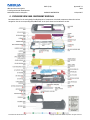
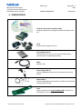
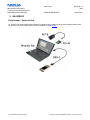
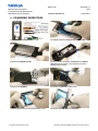
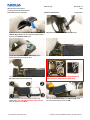
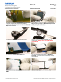
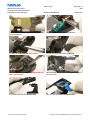
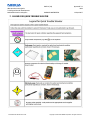
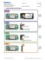
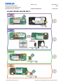
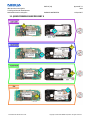
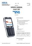
nokia CONNECTING PEOPLE CMO Operations & Logistics Training and Vendor Development Multimedia Creation & Support PAGE 1 (18) Approved 7.0 MGR COMPANY CONFIDENTIAL 12.Sept.2007 Transceiver characteristics: • Dual Band: EGSM and WCDMA (N70 only) -GSM: Tri-band phone for EGSM 900/1800/1900MHz -WCDMA: 2100MHz (N70 only) nokia nokia n70 RM-84 • -1. Camera: 2 Mega pixel (1600x1200pixels), 20x digital zoom n72 RM-180 Camera: -2. Camera: VGA (640x480pixels), 2x digital zoom ( N70 only) • Flash LED • Display: TFT active matrix color display with 262.144 colors, resolution 176 x 208 pixel • Bluetooth • FM radio: Stereo • Vibra Alert: Standard Vibra motor Talk time Standby Note EGSM WCDMA (N70 only) EGSM WCDMA (N70 only) 215 min 210 min 210 h 250 h • Connector: Pop Port Connector • MMC Reader Depends on network parameters Transceiver with BL-5C 970mAh Li-Ion battery pack Environmental characteristics: • Lead-free soldered SERVICE MANUAL Service Level 1&2 Service Manual N70 N72 Level 1&2 Copyright © 2005-2007 NOKIA Corporation. All rights reserved. nokia CONNECTING PEOPLE CMO Operations & Logistics Training and Vendor Development Multimedia Creation & Support PAGE 2 (18) Approved 7.0 MGR COMPANY CONFIDENTIAL 12.Sept.2007 TABLE OF CONTENT Page 1. INTRODUCTION ...........................................................................................................................................................3 2. EXPLODED VIEW AND COMPONENT DISPOSAL.........................................................................................................4 3. SPARE PARTS OVERVIEW............................................................................................................................................5 4. SERVICE DEVICES..........................................................................................................................................................6 5. SW-UPDATE .................................................................................................................................................................8 6. DISASSEMBLY INSTRUCTIONS....................................................................................................................................9 7. LEGEND FOR QUICK TROUBLE SHOOTER................................................................................................................. 14 8. QUICK TROUBLE SHOOTER PART 1 ......................................................................................................................... 15 9. QUICK TROUBLE SHOOTER PART 2 ......................................................................................................................... 16 10. QUICK TROUBLE SHOOTER PART 3..................................................................................................................... 17 11. QUICK TROUBLE SHOOTER PART 4..................................................................................................................... 18 CHANGE HISTORY Status Draft Approved Approved Approved Approved Approved Version No. 0.1 1.0 2.0 3.0 4.0 5.0 Date 01.07.2005 21.07.2005 19.08.2005 24.Apr.2006 02.Jan.2007 07.Mrz.2007 Approved Approved 6.0 7.0 07.May.2007 12.Sept.2007 Service Manual N70 N72 Level 1&2 Comments Initial draft Approval Disassembly instructions modified (picture Nr. 30) Nokia N72 (RM-180) added Exploded view / Spare Parts overview updated Wrong component name on page 20 corrected (S4401) Chapter Battery Test and GONOGO Test removed Exploded view and Spare Parts overview updated Exploded view and Spare Parts overview updated Copyright © 2005-2007 NOKIA Corporation. All rights reserved. nokia CONNECTING PEOPLE CMO Operations & Logistics Training and Vendor Development Multimedia Creation & Support PAGE 3 (18) Approved 7.0 MGR COMPANY CONFIDENTIAL 12.Sept.2007 1. INTRODUCTION The purpose of this document is to help NOKIA service levels 1 and 2 workshop technicians to service NOKIA products. This Service Manual must be used only by authorized NOKIA service suppliers. The content of it is confidential. Please note that NOKIA provides other guidance documents (e.g. Service Bulletins) for service suppliers. Follow these regularly and comply with the given instructions. While every effort has been made to ensure the accuracy of this document, some errors may exist. If you find any errors or if you have further suggestions, please notify NOKIA using the address below: mailto:[email protected] Please keep in mind also that this documentation is continuously being updated and modified, so always watch out for the newest version. Warnings and Cautions Please refer to the phone’s user guide for instructions relating to operation, care, and maintenance ,which include important safety information. Note also the following: Warnings: 1. CARE MUST BE TAKEN ON INSTALLATION IN VEHICLES FITTED WITH ELECTRONIC ENGINE MANAGEMENT SYSTEMS AND ANTI–SKID BRAKING SYSTEMS. UNDER CERTAIN FAULT CONDITIONS, EMITTED RF ENERGY CAN AFFECT THEIR OPERATION. IF NECESSARY, CONSULT THE VEHICLE DEALER/MANUFACTURER TO DETERMINE THE IMMUNITY OF VEHICLE ELECTRONIC SYSTEMS TO RF ENERGY. 2. THE CELLULAR TELEPHONE MUST NOT BE OPERATED IN AREAS LIKELY TO CONTAIN POTENTIALLY EXPLOSIVE ATMOSPHERES EG PETROL STATIONS (SERVICE STATIONS), BLASTING AREAS ETC. 3. OPERATION OF ANY RADIO TRANSMITTING EQUIPMENT, INCLUDING CELLULAR TELEPHONES, MAY INTERFERE WITH THE FUNCTIONALITY OF INADEQUATELY PROTECTED MEDICAL DEVICES. CONSULT A PHYSICIAN OR THE MANUFACTURER OF THE MEDICAL DEVICE IF YOU HAVE ANY QUESTIONS. OTHER ELECTRONIC EQUIPMENT MAY ALSO BE SUBJECT TO INTERFERENCE. Cautions: 1. Servicing and alignment must be undertaken by qualified personnel only. 2. Ensure all work is carried out at an anti–static workstation and that an anti–static wrist strap is worn. 3. Use only approved components as specified in the parts list. 4. Ensure all components, modules screws and insulators are correctly re–fitted after servicing and alignment. 5. Ensure all cables and wires are repositioned correctly. Electrostatic discharge can easily damage the sensitive components of electronic products. Therefore, every Service Supplier must observe the precautions, mentioned in the appropriate “Service Partner Requirements”, available on NOKIA Online. Also see ESD Protection Requirements in this Service Manual. Service Manual N70 N72 Level 1&2 Copyright © 2005-2007 NOKIA Corporation. All rights reserved. nokia CONNECTING PEOPLE CMO Operations & Logistics Training and Vendor Development Multimedia Creation & Support PAGE 4 (18) Approved 7.0 MGR COMPANY CONFIDENTIAL 12.Sept.2007 2. EXPLODED VIEW AND COMPONENT DISPOSAL Recommendation for the ecologically friendly disposal of components. Colorized components show the various categories. See the corresponding ITEM/CIRCUIT REF in the Spare Parts Service Bulletins on NOL. Service Manual N70 N72 Level 1&2 Copyright © 2005-2007 NOKIA Corporation. All rights reserved. nokia CONNECTING PEOPLE CMO Operations & Logistics Training and Vendor Development Multimedia Creation & Support PAGE 5 (18) Approved 7.0 MGR COMPANY CONFIDENTIAL 12.Sept.2007 3. SPARE PARTS OVERVIEW Service Manual N70 N72 Level 1&2 Copyright © 2005-2007 NOKIA Corporation. All rights reserved. nokia CONNECTING PEOPLE CMO Operations & Logistics Training and Vendor Development Multimedia Creation & Support PAGE 6 (18) Approved 7.0 MGR COMPANY CONFIDENTIAL 12.Sept.2007 4. SERVICE DEVICES FLS-4S incl. ACF-8, Driver and User Guide Dongle and flash device, package, developed specifically for POS use. ACF-8 Universal Power Supply for FLS-4S. Internal Battery BL-5C Inserted under the back cover, this Li-Ion 850 mAh battery provides power in a lightweight package. DKU-2 USB flash cable Travel Charger ACP-12 Small and lightweight charger for fast charging of your phone battery. Headset HDS-3 Small and lightweight stereo headset for handsfree functionality and listening to FM radio. SS-15 Camera removal tool for Camera Module 2MP. One side is for disassembly, the other side for assembly. Service Manual N70 N72 Level 1&2 Copyright © 2005-2007 NOKIA Corporation. All rights reserved. nokia CONNECTING PEOPLE CMO Operations & Logistics Training and Vendor Development Multimedia Creation & Support PAGE 7 (18) Approved 7.0 MGR COMPANY CONFIDENTIAL 12.Sept.2007 SS-51 Camera Removal Tool for CMOS Camera ( N70 only) SS-34 Flex Opening Tool RJ-94 Soldering Jig Lead-free Solder Wire Mandatory for lead-free products (Level 2 only). 0772040 Service Manual N70 N72 Level 1&2 NMP Standard Toolkit NOKIA opening tool SRT-6 NOKIA No. 0770431 Tonichi torque driver NOKIA No. 6901525 Hoya micro fiber cloth MX304 Dastex gloves S, M, XL Artilux goggles AH166 Wera bit T5 867/4TX 5x50 Wera 867/4 6IP; 50mm (Torx 6 PLUS®) Wera bit T6 867/4TX 6x50 Wera 867/1 5IP; 25mm (Torx 5 PLUS®) Wera bit T6 PLUS® 867/4TX 6IP Facom side cutter 416E Facom T5 driver SP.14032 Facom T6 driver SP.14033 Facom slot screwdriver AEF. 2x35.E Wetec tweezers 7abb SA-ESD Wetec tweezers 22 SA-ESD Wetec tweezers 13 SA-SMD ESD Wetec tweezers PSF SA-ESD Wetec ESD brush E1211 Kaiser Fototechnik airbrush 6315 Wetec dental tool DEM83266/0 RS Components Scissors 323-5732 Copyright © 2005-2007 NOKIA Corporation. All rights reserved. nokia CONNECTING PEOPLE CMO Operations & Logistics Training and Vendor Development Multimedia Creation & Support PAGE 8 (18) Approved 7.0 MGR COMPANY CONFIDENTIAL 12.Sept.2007 5. SW-UPDATE Flash Concept – (Point of Sales) To use the FLS-4S Flash Dongle you should have to follow the user’s guide inside the sales package. Always check for the latest version of flash software, which is available on NOKIA Online. Service Manual N70 N72 Level 1&2 Copyright © 2005-2007 NOKIA Corporation. All rights reserved. nokia CONNECTING PEOPLE CMO Operations & Logistics Training and Vendor Development Multimedia Creation & Support PAGE 9 (18) Approved 7.0 MGR COMPANY CONFIDENTIAL 12.Sept.2007 6. DISASSEMBLY INSTRUCTIONS 1.) You need the following tools. 2.) Always protect the window with a plastic film. 3.) Remove the Battery Cover. 4.) Place the SRT-6 between the A-Cover and Chassis Assy. Release the 4 plastic clips beginning from the bottom side as shown. 5.) Remove the Keymat 6.) Protect the LCD with a plastic film. 7.) Also protect the inner side window with a film 8.) Remove the MMC Door from A-Cover. Service Manual N70 N72 Level 1&2 Copyright © 2005-2007 NOKIA Corporation. All rights reserved. nokia CONNECTING PEOPLE CMO Operations & Logistics Training and Vendor Development Multimedia Creation & Support PAGE 10 (18) Approved 7.0 MGR COMPANY CONFIDENTIAL 12.Sept.2007 9.) Insert the SRT-6 between the Antenna Cover and Chassis Assy. Additional force may be required while opening the Antenna Cover clips. 10.) Remove the Power Button with tweezers. 11.) Protect the Camera Rear Bezel Assy with a plastic film before turning the unit. 12.) Remove the Camera gasket (N70 only). 13.) Unlock and remove the VGA Camera with the SS51 camera removal tool. (N70 only) 14.) Mind the correct position when fitting the Camera into its compartment. (N70 only) 15.) Unscrew the 6 Torx size 6 plus screws in the shown order. For Assembly use the reverse order and the torque of 25 Ncm. 16.) Lift the UI-frame Assy from Chassis Assy. Mind the still connected flex foil of the LCD. Service Manual N70 N72 Level 1&2 Copyright © 2005-2007 NOKIA Corporation. All rights reserved. nokia CONNECTING PEOPLE CMO Operations & Logistics Training and Vendor Development Multimedia Creation & Support PAGE 11 (18) Approved 7.0 MGR COMPANY CONFIDENTIAL 12.Sept.2007 17.) Open the flex connector with the SS-34 flex connector-opening tool. Mind the surrounding components while placing the tool. Now the UI-Frame Assy can be removed. 18.) Unlatch each clip of the LCD from the UI Frame Assy carefully by pulling the UI Frame Assy sideward while pushing the LCD forward. 19.) Remove the Earpiece with the dental tool 20.) Also remove the Earpiece Gasket from its compartment. Always use a new gasket when reassembling. 21.) Unlatch the BB shield Assembly first. 22.) Then push down and remove the BB Shield Assembly. The shield can’t be reused again, always use a new one. 23.) Pull the UI Frame Assy slightly to unlock the UI PWB. 24.) Now the UI PWB can be removed easily. Service Manual N70 N72 Level 1&2 Copyright © 2005-2007 NOKIA Corporation. All rights reserved. nokia CONNECTING PEOPLE CMO Operations & Logistics Training and Vendor Development Multimedia Creation & Support PAGE 12 (18) Approved 7.0 MGR COMPANY CONFIDENTIAL 12.Sept.2007 25.) Remove the Engine Module. Place it into the RJ94 jig immediately. 26.) Remove the Vibra Motor with tweezers. 27.) Pull out the Microphone with tweezers. 28.) Use the DC plug to remove the DC Jack. 29.) Lever out the IHF speaker. Mind the guide pin when reassembling. 30.) Unlock the 4 plastic clips of the Antenna Assy in the area shown. 31.) Carefully separate the Antenna Assy. 32.) Lever out the Camera Rear Bezel Assy. Service Manual N70 N72 Level 1&2 Copyright © 2005-2007 NOKIA Corporation. All rights reserved. nokia CONNECTING PEOPLE CMO Operations & Logistics Training and Vendor Development Multimedia Creation & Support PAGE 13 (18) Approved 7.0 MGR COMPANY CONFIDENTIAL 12.Sept.2007 33.) Remove the residues of the Camera Rear Bezel Assy Adhesive completely with the SRT-6. For assembly always use a new adhesive. 34.) Remove the Camera Module 2MP with the SS-15 camera removal tool. Always use the RJ-94 rework jig as support to prevent mechanical stress to the PWB. For assembly only! For assembly only! 35.) Use the Assembly side of the SS-15 for fitting the Camera Module 2MP into its compartment. 36.) Mind the correct position of the camera while assembling. Service Manual N70 N72 Level 1&2 Copyright © 2005-2007 NOKIA Corporation. All rights reserved. nokia CONNECTING PEOPLE CMO Operations & Logistics Training and Vendor Development Multimedia Creation & Support PAGE 14 (18) Approved 7.0 MGR COMPANY CONFIDENTIAL 12.Sept.2007 7. LEGEND FOR QUICK TROUBLE SHOOTER Service Manual N70 N72 Level 1&2 Copyright © 2005-2007 NOKIA Corporation. All rights reserved. nokia CONNECTING PEOPLE CMO Operations & Logistics Training and Vendor Development Multimedia Creation & Support PAGE 15 (18) Approved 7.0 MGR COMPANY CONFIDENTIAL 12.Sept.2007 8. QUICK TROUBLE SHOOTER PART 1 Service Manual N70 N72 Level 1&2 Copyright © 2005-2007 NOKIA Corporation. All rights reserved. nokia CONNECTING PEOPLE CMO Operations & Logistics Training and Vendor Development Multimedia Creation & Support PAGE 16 (18) Approved 7.0 MGR COMPANY CONFIDENTIAL 12.Sept.2007 9. QUICK TROUBLE SHOOTER PART 2 Service Manual N70 N72 Level 1&2 Copyright © 2005-2007 NOKIA Corporation. All rights reserved. nokia CONNECTING PEOPLE CMO Operations & Logistics Training and Vendor Development Multimedia Creation & Support PAGE 17 (18) Approved 7.0 MGR COMPANY CONFIDENTIAL 12.Sept.2007 10.QUICK TROUBLE SHOOTER PART 3 Service Manual N70 N72 Level 1&2 Copyright © 2005-2007 NOKIA Corporation. All rights reserved. nokia CONNECTING PEOPLE CMO Operations & Logistics Training and Vendor Development Multimedia Creation & Support PAGE 18 (18) Approved 7.0 MGR COMPANY CONFIDENTIAL 12.Sept.2007 11. QUICK TROUBLE SHOOTER PART 4 Service Manual N70 N72 Level 1&2 Copyright © 2005-2007 NOKIA Corporation. All rights reserved.