1
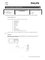
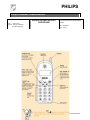
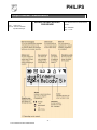
PHILIPS Philips Consumer Communications CUSTOMER SERVICES Author : Fabrice Tant Approval : Jean Pierre Hollande Operational Manager SERVICE REPAIR SUPPORT PROCEDURE PCC/VY/691/E/TCD188LVL2/0026/TF/MLD Creation Date : 26/06/2000 Page : 1 of 30 Service Manual Repair for Cellular Telephone SAVVY VOGUE DUAL BAND Level 1 & Level 2 -1- PCC/VY/691/E/TCD188LVL2/0026/TF/MLD PHILIPS Philips Consumer Communications CUSTOMER SERVICES Author : Fabrice Tant Approval : Jean Pierre Hollande Operational Manager SERVICE REPAIR SUPPORT PROCEDURE PCC/VY/691/E/TCD188LVL2/0026/TF/MLD Creation Date : 26/06/2000 Page : 2 of 30 Service Manual Updated dates: DATE MODIFICATION 27/06/2000 CREATION PAGE CONTENTS 1.0 PURPOSE....................................................................................................................................................................4 -2- PCC/VY/691/E/TCD188LVL2/0026/TF/MLD PHILIPS Philips Consumer Communications CUSTOMER SERVICES Author : Fabrice Tant Approval : Jean Pierre Hollande Operational Manager SERVICE REPAIR SUPPORT PROCEDURE PCC/VY/691/E/TCD188LVL2/0026/TF/MLD Creation Date : 26/06/2000 Page : 3 of 30 2.0 SCOPE..........................................................................................................................................................................4 3.0 REFERENCE...............................................................................................................................................................4 4.0 GLOSSARY / ACRONYM LIST..............................................................................................................................4 5.0 TEST EQUIPMENT AND TOOLS..........................................................................................................................4 6.0 TEST & INSPECTION PLAN...................................................................................................................................4 6.1 USER INTERFACE TEST ..........................................................................................................................................5 6.2 RF TEST.............................................................................................................................................................5 7.0 BEFORE YOU START..............................................................................................................................................6 7.1 DESCRIPTION OF THE TRANSCEIVER...........................................................................................................................6 7.2 THE DISPLAY......................................................................................................................................................12 7.3 INSERTING THE SIM CARD (MICRO).......................................................................................................................12 7.4 INSERTING THE BATTERY AND BATTERY COVER......................................................................................................12 7.5 REMOVING THE BATTERY COVER AND BATTERY .......................................................................................................13 7.6 CHARGING THE BATTERY......................................................................................................................................13 8.0 TEST PROCEDURES .............................................................................................................................................14 8.1INITIAL FUNCTIONAL CHECK FOR TCD188 SAVVY VOGUE.........................................................................................14 8.2 RF TEST...........................................................................................................................................................17 8.3 CHARGING IGN (IGNITION) - BATTERY.................................................................................................................19 9.0ASSEMBLY / DISMANTLEMENT PROCEDURES............................................................................................20 9.1 DISMANTLEMENT.................................................................................................................................................21 9.2ASSEMBLY..........................................................................................................................................................21 9.3 OVERVIEW.........................................................................................................................................................27 10.0DEFAULTS SETTINGS..........................................................................................................................................28 10.1 RESET CUSTOMER PARAMETERS . ..........................................................................................................................28 10.2 USE OF THE GSM STRING *#RSAV*# OR *#7728*#..........................................................................................29 11.0SOLUTIONS IN CASE OF PROBLEM DURING TESTS.................................................................................29 11.1 THE MOBILE DOES NOT SWITCH ON........................................................................................................................29 11.2 CHARGE DOES NOT START OR NO CHARGER DETECTION..............................................................................................30 11.3 THE DISPLAY SHOW “NO SIM CARD. PLEASE INSERT YOUR SIM CARD.” OR “SIM FAILURE”..................................30 11.4 DISPLAY PROBLEMS ...........................................................................................................................................30 11.5 BUZZER PROBLEMS ............................................................................................................................................30 11.6 NO SOUND IN LOUDSPEAKER...............................................................................................................................31 11.7 COMMUNICATIONS PROBLEMS ...............................................................................................................................31 11.8 DEFECTIVE ANTENNA..........................................................................................................................................31 11.9 KEYBOARD PROBLEMS ........................................................................................................................................31 11.10 CAN’T SEND SMS MESSAGES............................................................................................................................31 -3- PCC/VY/691/E/TCD188LVL2/0026/TF/MLD PHILIPS Philips Consumer Communications CUSTOMER SERVICES Author : Fabrice Tant Approval : Jean Pierre Hollande Operational Manager SERVICE REPAIR SUPPORT PROCEDURE PCC/VY/691/E/TCD188LVL2/0026/TF/MLD Creation Date : 26/06/2000 Page : 4 of 30 1.0 PURPOSE This document establishes the functional test procedures for service repair of SAVVY VOGUE transceiver. 2.0 SCOPE The test plan is applicable to all level of service repair of SAVVY VOGUE transceiver. 3.0 REFERENCE 4.0 GLOSSARY / ACRONYM LIST Window or Bezzel SW PN CN HW ASC NSC Test SIM card Test SIM card “SP” Protective plastic over the LCD display Software Hardware configuration of the Mobile Matrix for types of SW used on the different Hardware Hardware Authorized Service Center National Service Center Use for functionality of Philips Mobiles SIM card used to simulate user interface and allows radio tests 5.0 TEST EQUIPMENT AND TOOLS Equipment / Tools • • • • Production Test SIM Card Test SIM Card “SP” RF Cable Digital Multimeter - Part No. : 4311 255 00781 - Part No. : 4311 255 00782 - Part No. : 941-555-1 (AMP) - Recommended Model : Fluke Specification with current reading in mA 6.0 TEST & INSPECTION PLAN -4- PCC/VY/691/E/TCD188LVL2/0026/TF/MLD PHILIPS Philips Consumer Communications CUSTOMER SERVICES SERVICE REPAIR SUPPORT PROCEDURE Author : Fabrice Tant Approval : Jean Pierre Hollande Operational Manager PCC/VY/691/E/TCD188LVL2/0026/TF/MLD Creation Date : 26/06/2000 Page : 5 of 30 The following test & inspection plan is derived from the Product Test Reference for SAVVY VOGUE. 6.1 User Interface Test Using of TEST SIM Card “SP” / Production to test DUT as follow: ♦ ♦ ♦ ♦ ♦ ♦ ♦ ♦ ♦ ♦ ♦ On/Off Button LCD Back-light Keyboard Test Buzzer Test Audio Test Antenna Test LCD IMEI E-prom Status Production Number Transceiver 12NCs & Software Version With a fast charger connected to the PRODUCT car-kit, perform check on charging IGN (Ignition) – Battery. 6.2 RF Test The radio test must be performed with a Digital Radio Test Set connected with the specific RF cable to the mobile RF connector. -5- PCC/VY/691/E/TCD188LVL2/0026/TF/MLD PHILIPS Philips Consumer Communications CUSTOMER SERVICES Author : Fabrice Tant Approval : Jean Pierre Hollande Operational Manager SERVICE REPAIR SUPPORT PROCEDURE PCC/VY/691/E/TCD188LVL2/0026/TF/MLD Creation Date : 26/06/2000 Page : 6 of 30 7.0 Before You Start 7.1 Description of the transceiver -6- PCC/VY/691/E/TCD188LVL2/0026/TF/MLD PHILIPS Philips Consumer Communications CUSTOMER SERVICES Author : Fabrice Tant Approval : Jean Pierre Hollande Operational Manager SERVICE REPAIR SUPPORT PROCEDURE PCC/VY/691/E/TCD188LVL2/0026/TF/MLD Creation Date : 26/06/2000 Page : 7 of 30 -7- PCC/VY/691/E/TCD188LVL2/0026/TF/MLD PHILIPS Philips Consumer Communications CUSTOMER SERVICES Author : Fabrice Tant Approval : Jean Pierre Hollande Operational Manager SERVICE REPAIR SUPPORT PROCEDURE PCC/VY/691/E/TCD188LVL2/0026/TF/MLD Creation Date : 26/06/2000 Page : 8 of 30 -8- PCC/VY/691/E/TCD188LVL2/0026/TF/MLD PHILIPS Philips Consumer Communications CUSTOMER SERVICES Author : Fabrice Tant Approval : Jean Pierre Hollande Operational Manager SERVICE REPAIR SUPPORT PROCEDURE PCC/VY/691/E/TCD188LVL2/0026/TF/MLD Creation Date : 26/06/2000 Page : 9 of 30 -9- PCC/VY/691/E/TCD188LVL2/0026/TF/MLD PHILIPS Philips Consumer Communications CUSTOMER SERVICES Author : Fabrice Tant Approval : Jean Pierre Hollande Operational Manager PCC/VY/691/E/TCD188LVL2/0026/TF/MLD SERVICE REPAIR SUPPORT PROCEDURE PCC/VY/691/E/TCD188LVL2/0026/TF/MLD Creation Date : 26/06/2000 Page : 10 of 30 - 10 - PHILIPS Philips Consumer Communications CUSTOMER SERVICES Author : Fabrice Tant Approval : Jean Pierre Hollande Operational Manager PCC/VY/691/E/TCD188LVL2/0026/TF/MLD SERVICE REPAIR SUPPORT PROCEDURE PCC/VY/691/E/TCD188LVL2/0026/TF/MLD Creation Date : 26/06/2000 Page : 11 of 30 - 11 - PHILIPS Philips Consumer Communications CUSTOMER SERVICES Author : Fabrice Tant Approval : Jean Pierre Hollande Operational Manager SERVICE REPAIR SUPPORT PROCEDURE 7.2 The display 7.3 Inserting the SIM card (Micro). PCC/VY/691/E/TCD188LVL2/0026/TF/MLD Creation Date : 26/06/2000 Page : 12 of 30 7.3.1 Remove the SIM card from its support and slide the card into the appropriate slot in the battery compartment (the chip must be facing inwards and towards the bottom of the transceiver). 7.4 Inserting the Battery and Battery Cover. 7.4.1 Slide the battery onto the contact near the middle of the transceiver, and press the battery in place. 7.4.2 Hook the battery cover onto the hinges on bottom of transceiver and press forward until the latch catches. PCC/VY/691/E/TCD188LVL2/0026/TF/MLD - 12 - PHILIPS Philips Consumer Communications CUSTOMER SERVICES Author : Fabrice Tant Approval : Jean Pierre Hollande Operational Manager 7.5 SERVICE REPAIR SUPPORT PROCEDURE PCC/VY/691/E/TCD188LVL2/0026/TF/MLD Creation Date : 26/06/2000 Page : 13 of 30 Removing the Battery Cover and Battery. 7.5.1 Press on the latch on the back of the transceiver and lift off the battery cover. Lift up on the bottom of the battery and remove from the transceiver. 7.6 Charging the battery 7.6.1 With the battery attached to the phone, plug the connector into the right socket at the base of the phone. 7.6.2 Plug the transformer unit into an AC power socket. 7.6.3 The battery icon on the transceiver’s display indicates the state of the charge process: • Bars moving means the battery is charging. • Steady means the battery is fully charged. If the battery is completely discharged, the battery icon will only appear 2 to 3 minutes after you connect the charger. PCC/VY/691/E/TCD188LVL2/0026/TF/MLD - 13 - PHILIPS Philips Consumer Communications CUSTOMER SERVICES SERVICE REPAIR SUPPORT PROCEDURE Author : Fabrice Tant Approval : Jean Pierre Hollande Operational Manager PCC/VY/691/E/TCD188LVL2/0026/TF/MLD Creation Date : 26/06/2000 Page : 14 of 30 8.0 Test Procedures 8.1 Initial Functional Check for TCD188 Savvy Vogue 8.1.1 Insert the Test Production Card into the SIM Reader at the back of the cellular phone and clip on charged battery on to the phone. 8.1.2 Press ON - Button for at least 2 second and the LCD of the product shows the message : “FA GOOD xx”. 8.1.3 Following the instructions : Step 1 2 Procedure Press Key 1 Observation Continue Buzzer signal Press Key 1 again Left corner displays 1 00 The mobile sleeps for 5 minutes or wakes up after a key press and display the error code (00 means sleep mode successfully achieved Press key 2 Sleep Mode Test Press key 2 again 3 4 5 6 Press key 3 Audio loop test (Speak to Mic and listen echo from Speaker) Press key 3 again Press key 4 Left corner displays 2 01 "AUDIO xx xx "xx xx xx xx Left corner displays 3 02 Antenna test “Tx Level "05" (default) "CHANNEL 001" (default) Press key 4 again Left corner displays 4 03 Press Key 5 All pixels and hard icons on Press Key 5 again Left corner displays 5 04 Checkerboard 1 pixel on Press Key 6 (Checkerboard test) Press Key 6 again PCC/VY/691/E/TCD188LVL2/0026/TF/MLD Left corner displays 6 05 - 14 - a PHILIPS Philips Consumer Communications CUSTOMER SERVICES SERVICE REPAIR SUPPORT PROCEDURE Author : Fabrice Tant Approval : Jean Pierre Hollande Operational Manager 7 8 10 Page : 15 of 30 Press Key 7 (Inverted Checkerboard) Press key 7 again Press key 8 (Eeprom Status) Press Key 9 Product information Compare information with label printed on back case Press key 9 again Press key 0 (Vibrator Test) Press key 0 again 11 12 13 Creation Date : 26/06/2000 Press Key 8 again 9 PCC/VY/691/E/TCD188LVL2/0026/TF/MLD Press * (IMEI Test) Compare IMEI with label printed on back case Checkerboard 2 pixel on Left corner displays 7 06 "H XXXXXXXX" (No digit “1” or “2” allowed) "L XXXXXXXX" Left corner displays 8 07 PN number : “Vyxxxxx VY made in Le Mans SA made in Singapore EO made in Shenzhen Left corner displays 9 08 Display product 12NC # and software version The mobile’s vibrator is running Left corner displays 0 09 "IMEI TEST" " 449680/ 50 / xxxxxxx" for (TCD168) 06 made in Singapore 50 made in Le-Mans 69 made in China "Serial Number/ Check digit" Press * again Left corner displays * Press # (FA Status) 11 "FA GOOD XX” (Must be Good) Press # again Left corner displays # 12 Press C (Power Test) " Power"/ Channel/level "--/--/---" (ignore reading) Press C again Left corner displays C 13 PCC/VY/691/E/TCD188LVL2/0026/TF/MLD - 15 - PHILIPS Philips Consumer Communications CUSTOMER SERVICES SERVICE REPAIR SUPPORT PROCEDURE Author : Fabrice Tant Approval : Jean Pierre Hollande Operational Manager 14 15 16 PCC/VY/691/E/TCD188LVL2/0026/TF/MLD Creation Date : 26/06/2000 Page : 16 of 30 Press X (Left arrowhead) (Audio loop local effect) Press 8 (left dot) again "LocalEffect" " xx xx xx xx “ Press ø (Right arrowhead) Left corner displays . ← 0C "TypBat / xxxx" (ignore the number “TmpRad / xxxx displayed) Press Ð (Right arrowhead)again Left corner displays . → 0D Press MENU (Carkit Audio loop on/off) "CAR KIT” "xx xx xx " Press MENU again Left corner displays (ignore reading) 4 10 17 18 19 20 Press OK button ▼ (Memory Test) "Flash Checksum " (ignore Number) "Flash constructor ID / Flash type ID" (ignore #) “ OK" displayed vertically on the right Press OK button ▼ again Press Up button ▲ Left corner displays ▼ 0B User Melody Press ▲ button again Left corner displays ▲ 0A Press Green button “ MANUAL TEST” “ GOOD “ Press Green button again Left corner displays Press Red button “ MANUAL TEST” “ BAD “ Left corner displays Press Red button again >> 0E ❚❚ 0F 8.1.4 If any of the step failed functional, refer to Chapter 10. 8.1.5 Perform visual check on battery connectors, car kit connectors and casing. If corrosion or deform send to NSC for repair. 8.1.6 If the product is good, it is considered as a NFF product. All the NFF products must be directly returned to the customer. PCC/VY/691/E/TCD188LVL2/0026/TF/MLD - 16 - PHILIPS Philips Consumer Communications CUSTOMER SERVICES SERVICE REPAIR SUPPORT PROCEDURE Author : Fabrice Tant Approval : Jean Pierre Hollande Operational Manager PCC/VY/691/E/TCD188LVL2/0026/TF/MLD Creation Date : 26/06/2000 Page : 17 of 30 8.2 RF Test 8.2.1 The Test SIM Card “SP” must be inserted in to the phone before starting the test. 8.2.2 Set the equipment as shown in picture chapter 6.2 The RF cable to use is made by AMP (Part No.: 941-555-1) 8.2.3 Set in the offset field of the radio tester a - 0.3dBm lose for GSM Tests and a - 0.5dBm lose for PCN tests. 8.2.4 The followings operations must be done: - 8.2.5 Synchronization/Registration Call set up from the mobile Voice loopback (check sound quality) Call release Call set up from tester Call release from tester The followings parameters must be checked in TCH loop mode: Emission parameters - Power level RMS phase error Peak phase error Frequency error Power ramping Reception parameters - Rx level Rx quality BER (Byte Error Rate) FER (Frequency Error Rate) Generally the test sequences built-in the testers will be used to check the mobile. You must assess that the test sequences limits comply with the standard specifications. PCC/VY/691/E/TCD188LVL2/0026/TF/MLD - 17 - PHILIPS Philips Consumer Communications CUSTOMER SERVICES Author : Fabrice Tant Approval : Jean Pierre Hollande Operational Manager 8.2.6 SERVICE REPAIR SUPPORT PROCEDURE PCC/VY/691/E/TCD188LVL2/0026/TF/MLD Creation Date : 26/06/2000 Page : 18 of 30 GSM Specification (900 Mhz) Test Parameters EMISSION Phase error RMS Phase error Peak Frequency Error Power Ramping Modulation Switching Transcients Power reading Output Power RECEPTION Rx level Rx Qual Rx Level Rx Qual Rx Level Rx Qual Channel Level Standard Specification 1, 62, 124 1, 62, 124 1, 62, 124 1, 62, 124 1, 62, 124 1, 62, 124 5, 10, 15, 19 5, 10, 15, 19 5, 10, 15, 19 5, 10, 15, 19 5, 10, 15, 19 5, 10, 15, 19 0 to 5.0 degree -20 to +20 degree -90 Hz to +90 Hz Mask Mask Mask 1, 62, 124 1, 62, 124 1, 62, 124 1, 62, 124 Level 19 Level 15 Level 10 Level 5 5 dBm +/- 4.4 dB 13 dBm +/- 2.4 dB 21 dBm +/- 2.4 dB 32 dBm +/- 1.0 dB 1, 62, 124 1, 62, 124 1, 62, 124 1, 62, 124 1, 62, 124 -100 dBm -100 dBm -83 dBm -83 dBm -60 dBm -60 dBm 8 to 13 0 to 1 28 to 33 0 to 1 48 to 53 0 to 1 TCH LOOP SENSITIVITY 8.2.7 BER at -85dbm FER at -85dbm BER at –102dbm 1, 62, 124 1, 62, 124 1, 62, 124 0% 0% 2.44% FER at –102dbm 1, 62, 124 0% PCN Specification (1800 Mhz) PCC/VY/691/E/TCD188LVL2/0026/TF/MLD - 18 - PHILIPS Philips Consumer Communications CUSTOMER SERVICES Author : Fabrice Tant Approval : Jean Pierre Hollande Operational Manager SERVICE REPAIR SUPPORT PROCEDURE RECEPTION Rx level Rx Qual Rx Level Rx Qual Rx Level Rx Qual Creation Date : 26/06/2000 Page : 19 of 30 Test Parameters EMISSION Phase error RMS Phase error Peak Frequency Error Power Ramping Modulation Switching Transcients Power reading Output Power PCC/VY/691/E/TCD188LVL2/0026/TF/MLD Channel Level Standard Specification 512, 635, 760, 885 0, 5, 10 0, 5, 10 0, 5, 10 0, 5, 10 0, 5, 10 0, 5, 10 0 to 5.0 degree -20 to +20 degree -180 Hz to + 180 Hz Mask Mask Mask 512, 635, 760, 885 Level 15 Level 10 Level 5 Level 0 0 +/- 5.0 dBm 10 +/- 4.0 dBm 20 +/- 3.0 dBm 30 +/- 2.0 dBm 512, 635, 760, 885 -100dbm -100dbm -80dbm -80dbm -60dbm -60dbm 8 to 13 0 to 1 28 to 33 0 to 1 48 to 53 0 to 1 TCH LOOP SENSITIVITY BER at -85dbm FER at -85dbm BER at –102dbm FER at –102dbm 512, 635, 760, 885 0% 0% 2.44% 0% 8.3 Charging IGN (Ignition) - Battery 8.3.1 Plug the connector of the charger into the right socket at the base of the PRODUCT. PCC/VY/691/E/TCD188LVL2/0026/TF/MLD - 19 - PHILIPS Philips Consumer Communications CUSTOMER SERVICES Author : Fabrice Tant Approval : Jean Pierre Hollande Operational Manager SERVICE REPAIR SUPPORT PROCEDURE PCC/VY/691/E/TCD188LVL2/0026/TF/MLD Creation Date : 26/06/2000 Page : 20 of 30 The battery symbol should indicates the state of the charge process: Bars moving means the battery is charging. Steady means the battery is fully charged. If the battery is completely discharged, the battery icon will only appear 2 to 3 minutes after being connected to the charger. 8.3.2 Remove the charger by unplugging the connector of the charger out of the right socket at the base of the PRODUCT. Remove the battery. Remove the Production Test SIM card by gently sliding it out of the slot. 9.0 Assembly / Dismantlement procedures During dismantlement and assembly operations, an antistatic bracelet must be used. PCC/VY/691/E/TCD188LVL2/0026/TF/MLD - 20 - PHILIPS Philips Consumer Communications CUSTOMER SERVICES Author : Fabrice Tant Approval : Jean Pierre Hollande Operational Manager SERVICE REPAIR SUPPORT PROCEDURE PCC/VY/691/E/TCD188LVL2/0026/TF/MLD Creation Date : 26/06/2000 Page : 21 of 30 9.1 Dismantlement 9.1.1 Unscrew the ANTENNA 9.1.2 Take the product, remove TOP COVER and BATTERY 9.1.3 Remove the SIM card 9.1.4 Take the electrical screwdriver 9.1.5 Unscrew the M1,6x4,4mm screw on the SIM connector location 9.1.6 Unscrew the 5 M1,6x13,5mm screws 9.1.7 Unscrew the M1,6x9mm white screw 9.1.8 Remove the REAR CABINET 9.1.9 Remove the WHOLE BOARD from the FRONT CABINET 9.1.10 Remove the BATTERY CONTACTS from the connector (SUPPORT CONTACTS) 9.1.11 Unfasten the vibrator. 9.1.12 Remove the LCD JOINT 9.1.13 Unfasten the LCD Warning : Do not put your fingers on Zebra connector and copper areas 9.1.14 Unfasten the SUPPORT EARPIECE 9.1.15 Unscrew the M1,6x9mm white screw 9.1.16 Unfasten the SHIELDINGs 9.2 Assembly 9.2.1 Take set down the REAR SHIELDING on the antistatic tablecloth. 9.2.2 Take the BOARD and fix it on the REAR SHIELDING. 9.2.3 Check the presence and the straightness of the antenna contacts. PCC/VY/691/E/TCD188LVL2/0026/TF/MLD - 21 - PHILIPS Philips Consumer Communications CUSTOMER SERVICES Author : Fabrice Tant Approval : Jean Pierre Hollande Operational Manager SERVICE REPAIR SUPPORT PROCEDURE PCC/VY/691/E/TCD188LVL2/0026/TF/MLD Creation Date : 26/06/2000 Page : 22 of 30 Antenna contact Positionnig tip Positionnig tip 9.2.4 Take, fix the FRONT SHIELDING on the BOARD 9.2.5 Take the electrical screwdriver (screwdriver power 0,18 Nm) 9.2.6 Take and screw down a M1,6x9mm white screw on the SHIELDING 9.2.7 Attach the SUPPORT EARPIECE on the FRONT SHIELDING PCC/VY/691/E/TCD188LVL2/0026/TF/MLD - 22 - PHILIPS Philips Consumer Communications CUSTOMER SERVICES Author : Fabrice Tant Approval : Jean Pierre Hollande Operational Manager SERVICE REPAIR SUPPORT PROCEDURE Screw presence PCC/VY/691/E/TCD188LVL2/0026/TF/MLD Creation Date : 26/06/2000 Page : 23 of 30 Zebra copper area 9.2.8 Fasten the KEYPAD (don’t forget to lock the connector) Connector to lock 9.2.8 Take and fix the LCD on the BOARD 9.2.9 Attach the SUPPORT EARPIECE on the FRONT SHIELDING PCC/VY/691/E/TCD188LVL2/0026/TF/MLD - 23 - PHILIPS Philips Consumer Communications CUSTOMER SERVICES Author : Fabrice Tant Approval : Jean Pierre Hollande Operational Manager SERVICE REPAIR SUPPORT PROCEDURE PCC/VY/691/E/TCD188LVL2/0026/TF/MLD Creation Date : 26/06/2000 Page : 24 of 30 9.2.10 Remove the LCD PROTECTION 9.2.11 Take, put THE LCD JOINT on the LCD and EARPIECE Fastened Earpiece LCD module Window protection Inserts 9.2.12 Take, turn around the FRONT CABINET on the antistatic tablecloth 9.2.13 Check the presence of the 6 inserts and the window’s film protection 9.2.14 Blow on the LCD with the ionizing gun PCC/VY/691/E/TCD188LVL2/0026/TF/MLD - 24 Inserts PHILIPS Philips Consumer Communications CUSTOMER SERVICES SERVICE REPAIR SUPPORT PROCEDURE Author : Fabrice Tant Approval : Jean Pierre Hollande Operational Manager PCC/VY/691/E/TCD188LVL2/0026/TF/MLD Creation Date : 26/06/2000 Page : 25 of 30 9.2.15 Take the whole BOARD, return it into the FRONT CABINET Check the Joint buzzer presence Vibrator White screw Wires disposition under battery contacts 9.2.16 Check the white screw presence on the Shielding 9.2.17 Check the JOINT BUZZER presence 9.2.18 Take, plug the Vibrator cable to the small connector and set the VIBRATOR in the right location 9.2.19 Take, attach the BATTERY CONTACTS in the connector (SUPPORT CONTACT) 9.2.20 Dispose the wires above the connector Warning : no Wire should be discernable after the rear housing lock 9.2.21 Take, put the REAR HOUSING on the product 3 PCC/VY/691/E/TCD188LVL2/0026/TF/MLD 1 small screw - 25 - 4 PHILIPS Philips Consumer Communications CUSTOMER SERVICES SERVICE REPAIR SUPPORT PROCEDURE Author : Fabrice Tant Approval : Jean Pierre Hollande Operational Manager PCC/VY/691/E/TCD188LVL2/0026/TF/MLD Creation Date : 26/06/2000 Page : 26 of 30 2 white screw label 9.2.22 Take the electrical screwdriver 9.2.23 Take and screw down a M1,6x9mm white screw on the HOUSING 9.2.24 Take and screw down 5 M1,6x13,5mm screw on the HOUSING 9.2.25 Take and screw down a M1,6x4,4mm screw on the SIM connector location 9.2.26 Stick the LABEL on the back 9.2.27 Screw the ANTENNA PCC/VY/691/E/TCD188LVL2/0026/TF/MLD - 26 - 5 PHILIPS Philips Consumer Communications CUSTOMER SERVICES Author : Fabrice Tant Approval : Jean Pierre Hollande Operational Manager SERVICE REPAIR SUPPORT PROCEDURE Creation Date : 26/06/2000 Page : 27 of 30 9.3 Overview PCC/VY/691/E/TCD188LVL2/0026/TF/MLD PCC/VY/691/E/TCD188LVL2/0026/TF/MLD - 27 - PHILIPS Philips Consumer Communications CUSTOMER SERVICES SERVICE REPAIR SUPPORT PROCEDURE Author : Fabrice Tant Approval : Jean Pierre Hollande Operational Manager PCC/VY/691/E/TCD188LVL2/0026/TF/MLD Creation Date : 26/06/2000 Page : 28 of 30 LCD GASKET 4311.254.2151x EARPIECE HOLDER ASSEMBLY 4311.257.6048x LCD MODULE SCREW1.6X9 4311.250.4016x FRONT SHIELDING 4311.257.5121x PCB REAR SHIELDING 4311.257.5122x PCB ASSEMBLY C12 GSM SCALE 1.000 10.0 Defaults Settings 10.1 Reset customer parameters. To reset customer parameters, it must use a GSM String. This Gsm String is PCC/VY/691/E/TCD188LVL2/0026/TF/MLD - 28 - PHILIPS Philips Consumer Communications CUSTOMER SERVICES Author : Fabrice Tant Approval : Jean Pierre Hollande Operational Manager SERVICE REPAIR SUPPORT PROCEDURE PCC/VY/691/E/TCD188LVL2/0026/TF/MLD Creation Date : 26/06/2000 Page : 29 of 30 *#RSAV*# or *#7728*#. So, the defaults settings of the manufacturer are actived. 10.2 Use of the GSM string *#RSAV*# or *#7728*#. Procedure to follow : - 11.0 Turn on the mobile (a SP SIM card is not necessary). Enter the Gsm String *#RSAV*# or *#7728*#. You can see “Reset” but the customer parameters are not reset yet. Turn off the mobile. When you will turn on, the defaults settings will be actived. Solutions in case of problem during tests If for any reason the phone needs to be disassembled to fix a defect detected during the test procedure, a complete functional test and a RF test must be done. 11.1 The mobile does not switch on PCC/VY/691/E/TCD188LVL2/0026/TF/MLD - 29 - PHILIPS Philips Consumer Communications CUSTOMER SERVICES Author : Fabrice Tant Approval : Jean Pierre Hollande Operational Manager SERVICE REPAIR SUPPORT PROCEDURE PCC/VY/691/E/TCD188LVL2/0026/TF/MLD Creation Date : 26/06/2000 Page : 30 of 30 - Check the tactile feeling of the ON/OFF button. - Remove the battery. Check that both phone and battery contacts are not damaged. - Clean the contacts. - Plug the battery again, to be sure that it is securely fitted. Charge the mobile until the icon has stopped flashing. Then unplug it from the charger and try to switch the mobile on. If it’s still not switching on, try to fix the mobile. If the failure can’t be found out then send the mobile to repair. 11.2 Charge does not start or no charger detection - Check the charger contacts for dust or missing pins. - Check the mobile connector. - Remove the battery. Check that both phone and battery contacts are not damaged. - Check the charger individually with a reference mobile. If the charger is working properly try to charge the customer mobile with a reference battery. If neither the battery, nor the charger is to be incriminated, send the mobile for repair. 11.3 The display show “No SIM card. Please insert your SIM card.” Or “SIM FAILURE” - If the SIM card cannot be inserted, check for any foreign part and try to remove it. - Check the SIM card connector. All contacts must be at the same level. Examine that no dust is present on the connector contacts and on the SIM card contacts. If the SIM card connector is defective change it - If the test SIM card can be detected but the message “SIM Failure” remains with customer card, his card must be damaged. Ask the customer to contact his network operator. Otherwise send the mobile to repair 11.4 Display problems Contrast, icons and matrix of the display can be checked with the test SIM card by pressing keys 5, 6 and 7. If everything is working in test configuration that means that a phone setting is disable or not suitable. It can be solved in the phone menu. Change the LCD if necessary (not for small scratches). Otherwise send the mobile to repair 11.5 Buzzer problems Buzzer tone can be checked with the test SIM card by pressing keys 1 and . - If it does not sound properly, change the buzzer. If the failure can’t be found out then send the mobile to repair. PCC/VY/691/E/TCD188LVL2/0026/TF/MLD - 30 - PHILIPS Philips Consumer Communications CUSTOMER SERVICES Author : Fabrice Tant Approval : Jean Pierre Hollande Operational Manager 11.6 SERVICE REPAIR SUPPORT PROCEDURE PCC/VY/691/E/TCD188LVL2/0026/TF/MLD Creation Date : 26/06/2000 Page : 31 of 30 No sound in Loudspeaker - Check microphone and earpiece, change them if necessary. If the failure can not be found out, then send the mobile to repair. 11.7 Communications problems - Sound quality can be checked in audio loop test (sound distortion, whistling, echo, …) - If the mobile passes the radio test successfully, we can assume that the phone is working properly. The customer must check the coverage area of his network operator or that he is not using the phone in a radio shadow (outside the coverage area, in a tunnel or between tall buildings, …) - If the mobile does not pass the radio test send the mobile for repair. 11.8 Defective antenna - If the antenna is broken or curved => replace it 11.9 Keyboard problems -The keyboard can be checked with the test SIM card. - If a key or a row is not responding, check the keyboard, change it if necessary. If the failure cannot be found out, send the mobile to repair. 11.10 Can’t send SMS messages - Check the center number. Maybe it is empty or wrong. ANNEX 1 PCC/VY/691/E/TCD188LVL2/0026/TF/MLD - 31 - PHILIPS Philips Consumer Communications CUSTOMER SERVICES Author : Fabrice Tant Approval : Jean Pierre Hollande Operational Manager SERVICE REPAIR SUPPORT PROCEDURE Creation Date : 26/06/2000 Page : 32 of 30 Each returned product must have an IRIS code to identify the failure PCC/VY/691/E/TCD188LVL2/0026/TF/MLD PCC/VY/691/E/TCD188LVL2/0026/TF/MLD - 32 - PHILIPS Philips Consumer Communications CUSTOMER SERVICES Author : Fabrice Tant Approval : Jean Pierre Hollande Operational Manager SERVICE REPAIR SUPPORT PROCEDURE PCC/VY/691/E/TCD188LVL2/0026/TF/MLD Creation Date : 26/06/2000 Page : 33 of 30 ANNEX 2 : Recommended Part List – TCD188 COMMON PARTS - Out of Warranty REFERENCE DESIGNATION POSITION REPAIR LEVEL 4311 257 60746 4311 257 60735 4311 257 51237 4311 258 10153 4311 250 40154 4311 250 40164 4311 250 40223 4311 258 73511 2722 171 07182 2422 033 00293 4311 254 24642 4311 254 21265 242203300293 431125751445 431125751455 431125872452 431125872462 431125872413 312242720943 FRONT SHIELDING REAR SHEILDING ASS'Y REAR HOUSING ASS'Y C12C13 SUPPORT CONTACT ASS'Y SCREW M1,6x13,5 SCREW M1,6x9 SCREW TORX M1,6 4x4 FIXE ANTENNA C13 DB LCD AD 47306 CON CCM04-1402-R901 GASKET MICRO C13DB GASKET LCD C13/C13DB CON CCM04-1402-R901+B50 Plus Top cover Batt Ass’y AAWB Slim Top cover Batt Ass’y AAAWB Battery Slim 700 mAH Battery Plus Standard Charger EC Fast Charger Europe 0101 0102 0104 0113 0178 0176 0177 1708 1710 1501 0179 0180 1501 0090 0090 - 2 2 2 2 2 2 2 1 2 2 2 2 2 1 1 1 1 1 1 PCC/VY/691/E/TCD188LVL2/0026/TF/MLD - 33 - PHILIPS Philips Consumer Communications CUSTOMER SERVICES SERVICE REPAIR SUPPORT PROCEDURE Author : Fabrice Tant Approval : Jean Pierre Hollande Operational Manager 8 PCC/VY/691/E/TCD188LVL2/0026/TF/MLD Creation Date : 26/06/2000 Page : 34 of 30 France OPERATOR REFERENCE DESIGNATION POSITION LEVEL 4311 254 34852 4311 254 34872 4311 257 53243 4311 257 53263 4311 258 60103 4311 258 60123 WINDOW NAVY BLUE WINDOW CORAL BRONZE FRONT HOUSSING ASS’Y NB FRONT HOUSSING YACHT META KEYBOARD + HOLDER NB KEYPAD + HOLDER C14 COR B 0080 0080 0103 0103 0110 0110 REFERENCE DESIGNATION POSITION 4311 254 34861 4311 254 34851 4311 254 34841 4311 254 34871 4311 257 53253 4311 257 52193 4311 257 53233 4311 257 53263 4311 258 60113 4311 258 60103 4311 258 60093 4311 258 60123 WINDOW AQUA-GREEN WINDOW DEEP- BLUE WINDOW BLUE-WAVE WINDOW YACHT-METAL FRONT HOUSSING AQUA GREEN FRONT HOUSING ASS’Y NB FRONT HOUSING ASS’Y LB FRONT HOUSING YACHT META KEYPAD + HOLDER AQUA GRE KEYBOARD + HOLDER NB KEYPAD + HOLDER ASS’Y LB KEYPAD + HOLDER C14 COR B 0080 0080 0080 0080 0103 0103 0103 0103 0110 0110 0110 0110 2 2 2 2 2 2 2 2 2 2 2 2 4311 254 34852 4311 254 34842 4311 257 53243 4311 257 53233 4311 258 60103 4311 258 60093 WINDOW DEEP BLUE WINDOW BLUE WAVE FRONT HOUSING ASS’Y NB FRONT HOUSSING ASS’Y LB KEYBOARD + HOLDER NB KEYPAD + HOLDER ASS’Y LB 0080 0080 0103 0103 0110 0110 2 2 2 2 2 2 REFERENCE DESIGNATION POSITION FTM d 2 2 2 2 2 2 Spain OPERATOR LEVEL TELSTRA TELECEL Ð Germany OPERATOR PCC/VY/691/E/TCD188LVL2/0026/TF/MLD - 34 - LEVEL PHILIPS Philips Consumer Communications CUSTOMER SERVICES SERVICE REPAIR SUPPORT PROCEDURE Author : Fabrice Tant Approval : Jean Pierre Hollande Operational Manager PCC/VY/691/E/TCD188LVL2/0026/TF/MLD Creation Date : 26/06/2000 Page : 35 of 30 E-PLUS 4311 254 34852 4311 257 53243 4311 258 60103 WINDOW DEEP-BLUE FRONT HOUSING ASS’Y NB KEYBOARD + HOLDER NB 0080 0103 0110 2 2 2 43 11 254 35901 4311 254 35891 4311 257 53253 4311 257 53243 4311 258 60113 4311 258 60103 WINDOW D2 AQUA GREEN WINDOW D2 NAVY BLUE FRONT HOUSING AQUA GREEN KEYBAORD + HOLDER NB KEYPAD + HOLDER AQUA GRE KEYBOARD + HOLDER NB 0080 0080 0103 0103 0110 0110 2 2 2 2 2 2 D2 PCC/VY/691/E/TCD188LVL2/0026/TF/MLD - 35 -