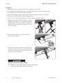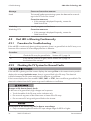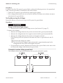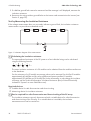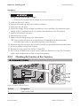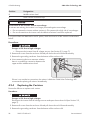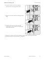
1
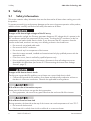
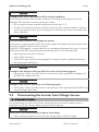
Service Manual SUNNY BOY 1300TL/1600TL/2100TL SB13-21TL-SG-en-11 | Version 1.1 AMERICAN ENGLISH Table of Contents SMA Solar Technology AG Table of Contents 1 2 Information on this Document ................................................. 4 1.1 1.2 1.3 1.4 Validity ................................................................................................ Target Group...................................................................................... Symbols .............................................................................................. Nomenclature..................................................................................... 4 4 4 5 Safety......................................................................................... 6 2.1 2.2 Safety Information.............................................................................. 6 Disconnecting the Inverter from Voltage Sources ............................ 7 3 Cleaning the Inverter................................................................ 10 4 Troubleshooting ........................................................................ 11 4.1 4.2 Error Messages .................................................................................. 11 Red LED is Glowing Continuously..................................................... 16 4.2.1 4.2.2 4.2.3 4.2.4 Procedure for Troubleshooting ...................................................... Checking the PV System for Ground Faults.................................. Checking the Function of the Varistors.......................................... Replacing the Varistors .................................................................. 16 16 19 20 5 Recommissioning the Inverter.................................................. 22 6 Decommissioning the Inverter ................................................. 24 7 Spare Parts ................................................................................ 25 8 Contact....................................................................................... 26 2 SB13-21TL-SG-en-11 Service Manual SMA Solar Technology AG Legal Provisions Legal Provisions The information contained in these documents is property of SMA Solar Technology AG. Any publication, whether in whole or in part, requires prior written approval by SMA Solar Technology AG. Internal reproduction used solely for the purpose of product evaluation or other proper use is allowed and does not require prior approval. SMA Warranty You can download the current warranty conditions from the Internet at www.SMA-Solar.com. Trademarks All trademarks are recognized, even if not explicitly identified as such. A lack of identification does not mean that a product or symbol is not trademarked. The BLUETOOTH® word mark and logos are registered trademarks of Bluetooth SIG, Inc. and any use of these marks by SMA Solar Technology AG is under license. Modbus® is a registered trademark of Schneider Electric and is licensed by the Modbus Organization, Inc. QR Code is a registered trademark of DENSO WAVE INCORPORATED. Phillips® and Pozidriv® are registered trademarks of Phillips Screw Company. Torx® is a registered trademark of Acument Global Technologies, Inc. SMA Solar Technology AG Sonnenallee 1 34266 Niestetal Germany Tel. +49 561 9522-0 Fax +49 561 9522-100 www.SMA.de E-mail: [email protected] © 2004 to 2014 SMA Solar Technology AG. All rights reserved. Service Manual SB13-21TL-SG-en-11 3 1 Information on this Document 1 SMA Solar Technology AG Information on this Document 1.1 Validity This document describes how to rectify certain errors and how to replace defective components. This document supplements the documents that are enclosed with each product and does not replace any locally applicable standards or directives. Read and observe all documents supplied with the product. This document is valid for the following device types from firmware version 4.50: • Sunny Boy 1300TL (SB 1300TL-10) • Sunny Boy 1600TL (SB 1600TL-10) • Sunny Boy 2100TL (SB 2100TL) 1.2 Target Group The tasks described in this document must only be performed by qualified persons. Qualified persons must have the following skills: • Registered qualification for electrically qualified person, level 1 and 2 • Knowledge of how an inverter works and is operated • Training in how to deal with the dangers and risks associated with installing and using electrical devices and installations • Training in the installation and commissioning of electrical devices and installations • Knowledge of the applicable standards and directives • Knowledge of and compliance with this document and all safety information • Knowledge of building structures and building materials 1.3 Symbols Symbol Explanation Indicates a hazardous situation which, if not avoided, will result in death or serious injury Indicates a hazardous situation which, if not avoided, can result in death or serious injury Indicates a hazardous situation which, if not avoided, can result in minor or moderate injury Indicates a situation which, if not avoided, can result in property damage Information that is important for a specific topic or goal, but is not safety-relevant Indicates a requirement for meeting a specific goal 4 SB13-21TL-SG-en-11 Service Manual 1 Information on this Document SMA Solar Technology AG Symbol Explanation Desired result A problem that might occur 1.4 Nomenclature Complete designation Designation in this document Sunny Boy Inverter, product Electronic Solar Switch ESS SMA BLUETOOTH Wireless Technology BLUETOOTH Service Manual SB13-21TL-SG-en-11 5 2 Safety 2 2.1 SMA Solar Technology AG Safety Safety Information This section contains safety information that must be observed at all times when working on or with the product. To prevent personal injury and property damage and to ensure long-term operation of the product, read this section carefully and observe all safety information at all times. Danger to life due to high voltages of the PV array When exposed to sunlight, the PV array generates dangerous DC voltage which is present in the DC conductors and the live components of the inverter. Touching the DC conductors or the live components can lead to lethal electric shocks. If you disconnect the DC connectors from the inverter under load, an electric arc may occur leading to electric shock and burns. • Do not touch uninsulated cable ends. • Do not touch the DC conductors. • Do not touch any live components of the inverter. • Have the inverter mounted, installed and commissioned only by qualified persons with the appropriate skills. • If an error occurs, have it rectified by qualified persons only. • Prior to performing any work on the inverter, disconnect it from all voltage sources as described in this document (see Section 2.2 "Disconnecting the Inverter from Voltage Sources", page 7). Danger to life due to electric shock Touching an ungrounded PV module or array frame can cause a fatal electric shock. • Connect and ground the PV modules, array frame and electrically conductive surfaces so that there is continuous conduction. Observe the applicable local regulations. Risk of burns due to hot enclosure parts Some parts of the enclosure can get hot during operation. • During operation, do not touch any parts other than the enclosure lid of the inverter. Risk of burns from hot heat sink During operation, the heat sink at the top of the inverter can reach temperatures of over 70°C. • Do not touch the heat sink. • If the heat sink is soiled, clean it with a soft brush or a vacuum cleaner. 6 SB13-21TL-SG-en-11 Service Manual 2 Safety SMA Solar Technology AG Damage to the seal of the enclosure lid in sub-zero conditions If you open the enclosure lid in sub-zero conditions, the sealing of the enclosure lid can be damaged. This can lead to moisture entering the inverter. • Do not open the inverter at ambient temperatures lower than -5°C. • If a layer of ice has formed on the seal of the enclosure lid in sub-zero conditions, remove it prior to opening the inverter (e.g. by melting the ice with warm air). Observe the applicable safety regulations. Dust and water intrusion can damage the inverter. If the inverter is equipped with an ESS, the inverter complies with degree of protection IP65 when the ESS is plugged in and the inverter is closed. If the ESS is not plugged in, moisture and dust can penetrate and damage the inverter. In order to sufficiently protect the inverter during decommissioning, the DC inputs must be closed. • Unlock and remove all DC connectors. • Open all DC connectors. • Close all DC inputs with the corresponding DC connectors and the supplied sealing plugs. • Securely plug the ESS back in. Damage to the display or the type label due to the use of cleaning agents • If the inverter is dirty, clean the enclosure, the enclosure lid, the type label, the display and the LEDs with a damp cloth only. Damage to the inverter due to the use of cleaning agents • If the inverter is dirty, clean the enclosure, the enclosure lid, the type label and the LEDs using only clean water and a cloth. 2.2 Disconnecting the Inverter from Voltage Sources Prior to performing any work on the inverter, always disconnect it from all voltage sources as described in this section. Always adhere to the prescribed sequence. Destruction of the measuring device due to overvoltage • Only use measuring devices with a DC input voltage range of 600 V or higher. Service Manual SB13-21TL-SG-en-11 7 2 Safety SMA Solar Technology AG Procedure: 1. Disconnect the circuit breaker and secure it against reconnection. 2. If an external DC load-break switch is installed, disconnect it from all voltage sources. 3. If an ESS is installed, carefully remove the ESS. 4. If the fault indicator relay is used, switch off the load supply voltage, if necessary. 5. Wait until the LEDs and the display have gone out. 6. Use a current clamp to ensure that no current is present in the DC cables. 7. Release and remove all DC connectors. Insert a flat-blade screwdriver or an angled screwdriver (blade width: 3.5 mm) into one of the side slots and pull the DC connectors straight out. Do not pull on the cable. 8. Ensure that no voltage is present at the DC inputs on the inverter. 9. Pull the AC connection socket out of the AC pin connector on the inverter. Turn the bush insert of the AC connection socket to the left until the AC connection socket releases. 10. Danger to life due to high voltages The capacitors in the inverter take ten minutes to discharge. • Wait ten minutes before opening the inverter. 8 SB13-21TL-SG-en-11 Service Manual 2 Safety SMA Solar Technology AG 11. Damage to the inverter due to electrostatic discharge Touching electronic components can cause damage to or destroy the inverter through electrostatic discharge. • Ground yourself before touching any component. Service Manual SB13-21TL-SG-en-11 9 3 Cleaning the Inverter 3 SMA Solar Technology AG Cleaning the Inverter Risk of burns from hot heat sink During operation, the heat sink at the top of the inverter can reach temperatures of over 70°C. • Do not touch the heat sink. • If the heat sink is soiled, clean it with a soft brush or a vacuum cleaner. Damage to the display or the type label due to the use of cleaning agents • If the inverter is dirty, clean the enclosure, the enclosure lid, the type label, the display and the LEDs with a damp cloth only. 10 SB13-21TL-SG-en-11 Service Manual 4 Troubleshooting SMA Solar Technology AG 4 Troubleshooting 4.1 Error Messages Errors, disturbances and warnings are shown in the display and start in the first line with the word "Error", "Disturbance" or "Warning". In the second line of the display, the cause of the error, disturbance or warning is shown. Message Cause and corrective measure !PV-Overvoltage! !! - ! DISCONNECT DC! Overvoltage at the DC input. This can destroy the inverter. This message is additionally highlighted by rapid flashing of the backlight. Corrective measures: • Disconnect the circuit breaker. • If installed, disconnect the external DC load-break switch. • If an ESS is plugged in, remove it. • Unlock and remove all DC connectors using a screwdriver (blade width: 3.5 mm): – Insert the screwdriver into one of the side slots. – Remove the DC connectors. • Check whether the DC voltage is below the maximum input voltage of the inverter. If the DC voltage is below the maximum input voltage of the inverter, reconnect the DC connectors to the inverter. If the DC voltage is above the maximum input voltage of the inverter, check the PV system design or contact the installer of the PV array. • If this message is repeated frequently, disconnect the inverter from voltage sources (see Section 2.2 "Disconnecting the Inverter from Voltage Sources", page 7) and contact the SMA Service Line. Service Manual SB13-21TL-SG-en-11 11 4 Troubleshooting SMA Solar Technology AG Message Cause and corrective measure ACVtgRPro The ten-minute average value of the grid voltage is no longer within the permissible range. The grid voltage or grid impedance at the connection point is too high. The inverter disconnects from the utility grid to maintain power quality. Corrective measures: • Check whether the grid voltage at the connection point of the inverter is permanently in the permissible range. If the line voltage is 253 V or higher, contact the grid operator. Ask the grid operator whether the voltage can be adapted at the feed-in point or whether it would be acceptable to change the threshold of the ACVtgRPro/Voltage increase protection parameter. If the grid voltage is permanently within the permissible range and this message is still displayed, contact the SMA Service Line. Bfr-Srr Internal measurement comparison fault or hardware defect. Corrective measures: • Contact the SMA Service Line if this disturbance occurs frequently. Check PE The grounding cable is not connected. Corrective measures: • Ensure that the AC cable is correctly connected (see the operating manual of the inverter). • If the AC cable is connected correctly and this message is still displayed, contact the SMA Service Line. Derating The inverter reduces its power output due to overheating. Corrective measures: • Ensure sufficient ventilation. dI-Mess Deviation in the differential current measurement. If this message is displayed frequently, permanent operation inhibition will be triggered. Corrective measures: • Contact the SMA Service Line. 12 SB13-21TL-SG-en-11 Service Manual 4 Troubleshooting SMA Solar Technology AG Message Cause and corrective measure dI Fault Curr-current control unit The inverter has detected a change in the differential current. A change in the differential current can be caused by a ground fault, residual current or a malfunction. The inverter disconnects from the utility grid. Corrective measures: • If none of the above causes apply and this message is still displayed, ensure that the PV system is insulated correctly and that no ground fault is present (see Section 4.2.2 "Checking the PV System for Ground Faults", page 16). EEPROM Temporary disturbance during reading or writing of data from the EEPROM. The data is not essential for safe operation. This message is for information purposes and has no effect on the performance of the inverter. EEPROM Data EEPROM defective. The inverter switches off because the loss of data has disabled important inverter functions. Corrective measures: • Contact the SMA Service Line. EeRestore One of the duplicate records in the EEPROM is defective and has been reconstructed without loss of data. This error message is only for information purposes and has no effect on the performance of the inverter. Fac Fac-Bfr FacFast Fac-Srr The power frequency is outside the permissible range. The inverter has disconnected from the utility grid. Corrective measures: • Ensure that the AC cable is correctly connected (see the operating manual of the inverter). • Ensure that the power frequency is within the permissible range. • If the power frequency is in the permissible range and this message is still displayed, contact the SMA Service Line. GOOSE Timeout No valid GOOSE commands have been received for one minute. The GOOSE-GoAppID is incorrectly configured or no data can be transmitted. Corrective measures: • Check the network cabling and the parameter setting. • Load default values if GOOSE has been activated inadvertently. Service Manual SB13-21TL-SG-en-11 13 4 Troubleshooting SMA Solar Technology AG Message Cause and corrective measure Iac-DC_Offs-Srr Iac-DC_Offs-Bfr Excessive DC current has been detected during feed-in operation. Corrective measures: • Ensure that the grid conditions are complied with. • If this message is displayed frequently or recurrently, contact the SMA Service Line. Imax Overcurrent on the AC side. The current at the AC terminal is higher than specified. Corrective measures: • Ensure that the PV system is designed correctly. • Ensure that the grid conditions are complied with. K1-Close K1-Open K2-Open Fault during relay test. Corrective measures: • If this disturbance occurs frequently or several times consecutively, contact the SMA Service Line. MSD-dI MSD‑Fac MSD-Vac MSD-Timeout Internal measurement comparison fault or the hardware is defective. Corrective measures: • If this message is displayed frequently, contact the SMA Service Line. Offset Disturbance in recording measured values. Corrective measures: • If this message is displayed frequently, contact the SMA Service Line. Earthfault The electrical insulation between the PV system and ground is defective. The resistance between the positive and negative DC terminal to ground is outside the permissible range. Corrective measures: • Ensure that the PV system is insulated correctly. • Check the PV array for ground faults (see Section 4.2.2, page 16 ). ROM The inverter firmware is faulty. Corrective measures: • If this message is displayed frequently, contact the SMA Service Line. Shutdown Temporary inverter disturbance. Corrective measures: • Contact the SMA Service Line. 14 SB13-21TL-SG-en-11 Service Manual 4 Troubleshooting SMA Solar Technology AG Message Cause and corrective measure STM Timeout Internal program run disturbance Corrective measures: • If this message is displayed frequently, contact the SMA Service Line. Vac-Bfr Vac-Srr The line voltage is no longer within the permissible range. The inverter has disconnected from the utility grid for safety reasons. This can be caused by one of the following: • The circuit breaker is switched off. • The AC cable is interrupted or highly resistive. Corrective measures: • Ensure that the AC cable is correctly connected (see the operating manual of the inverter). • Ensure that the grid voltage is in the permissible range. • Ask the grid operator for permission to change the parameters Vac-Min / Voltage monitoring upper minimum threshold and Vac-Max / Voltage monitoring lower maximum threshold. • If the AC cable is connected correctly, the grid voltage is within the permissible range and this message is still displayed, contact the SMA Service Line. UpvMax Overvoltage at the DC input. This can destroy the inverter. Corrective measures: 1. Disconnect the circuit breaker. 2. If there is an external DC load-break switch, turn it off. 3. If an ESS is plugged in, remove it. 4. Unlock and remove all DC connectors using a screwdriver (blade width: 3.5 mm): • Insert the screwdriver into one of the side slots. • Remove the DC connectors. 5. Check whether the DC voltage is below the maximum input voltage of the inverter. If the DC voltage is below the maximum input voltage of the inverter, reconnect the DC connectors to the inverter. If the DC voltage is above the maximum input voltage of the inverter, check the design of the PV system. 6. If this message is repeated frequently, disconnect the inverter from voltage sources (see Section 2.2, page 7) and contact the SMA Service Line. Service Manual SB13-21TL-SG-en-11 15 4 Troubleshooting SMA Solar Technology AG Message Cause and corrective measure Uzwk The internal hardware monitoring system has detected an overvoltage in the DC link of the inverter. Corrective measures: • If this message is displayed frequently, contact the SMA Service Line. Watchdog Watchdog CCU Internal program run disturbance Corrective measures: • If this message is displayed frequently, contact the SMA Service Line. 4.2 Red LED is Glowing Continuously 4.2.1 Procedure for Troubleshooting If the red LED is continuously glowing during operation, there is a ground fault in the PV array or at least one of the varistors for overvoltage protection is defective. Procedure See 1. Check the PV array for ground faults. 2. If the red LED continues to glow, check Section 4.2.3, page 19 the function of the varistors. 4.2.2 Section 4.2.2, page 16 Checking the PV System for Ground Faults If the red LED is glowing and the inverter displays the message Riso or the communication product displays the message Insulation error, there is a ground fault in the PV array. The electrical insulation between the PV system and ground is defective or insufficient. If the inverter displays the event numbers 3501, 3601 or 3701, there could be a ground fault. The electrical insulation from the PV system to ground is defective or insufficient. Danger to life due to electric shock In the event of a ground fault, high voltages can be present. • Touch the cables of the PV array on the insulation only. • Do not touch any parts of the substructure or frame of the PV array. • Do not connect PV strings with ground faults to the inverter. Destruction of the measuring device due to overvoltage • Only use measuring devices with a DC input voltage range of 600 V or higher. 16 SB13-21TL-SG-en-11 Service Manual 4 Troubleshooting SMA Solar Technology AG Procedure: In order to check the PV system for ground faults, perform the following actions in the prescribed order. The exact procedure is described in the sections below. • Check the PV system for ground faults by measuring the voltage. • If the voltage measurement was not successful, check the PV system via insulation resistance measurement for ground faults. Test by Measuring the Voltage Proceed as follows to check each string in the PV system for ground faults. Procedure: 1. Danger to life due to high voltages • Disconnect the inverter from all voltage sources (see Section 2.2, page 7). 2. Measure the voltages: • Measure the voltages between the positive terminal and the ground potential (PE). • Measure the voltage between the negative terminal and the ground potential (PE). • Measure the voltages between the positive and negative terminals. If the following results are present at the same time, there is a ground fault in the PV system: ☑ All measured voltages are stable. ☑ The sum of the two voltages to ground potential is approximately equal to the voltage between the positive and negative terminals. • If a ground fault is present, determine the location of the ground fault via the ratio of the two measured voltages and eliminate the ground fault. Example: Location of the ground fault The example shows a ground fault between the second and third PV module. Service Manual SB13-21TL-SG-en-11 17 4 Troubleshooting SMA Solar Technology AG 3. If a definite ground fault cannot be measured and the message is still displayed, measure the insulation resistance. 4. Reconnect the strings without ground faults to the inverter and recommission the inverter (see Section 5, page 22). Test by Measuring the Insulation Resistance If the voltage measurement does not accurately indicate a ground fault, the insulation resistance measurement can provide more detailed results. Figure 1: Schematic diagram of the measurement Calculating the insulation resistance The expected total resistance of the PV system or of an individual string can be calculated using the following formula: total The exact insulation resistance of a PV module can be obtained from the module manufacturer or the datasheet. For the resistance of a PV module an average value can be assumed: for thin-film PV modules approximately 40 MOhm and for polycrystalline and monocrystalline PV modules approximately 50 MOhm per PV module (for further information on calculating the insulation resistance see the Technical Information "Insulation Resistance (Riso) of Non-Galvanically Isolated PV Systems" at www.SMA-Solar.com). Required devices: ☐ Suitable device for safe disconnection and short-circuiting ☐ Measuring device for insulation resistance Device required for safe disconnection and short-circuiting of the PV array The insulation resistance can only be measured with a suitable device for safe disconnection and short-circuiting of the PV array. If no suitable device is available, the insulation measurement must not be carried out. 18 SB13-21TL-SG-en-11 Service Manual 4 Troubleshooting SMA Solar Technology AG Procedure: 1. Calculate the expected insulation resistance per string. 2. Danger to life due to high voltages • Disconnect the inverter from all voltage sources (see Section 2.2, page 7). 3. 4. 5. 6. 7. 8. 9. 10. 11. 12. 13. Install the short circuit device. Connect the measuring device for insulation resistance. Short-circuit the first string. Set the test voltage. The test voltage should be as close as possible to the maximum system voltage of the PV modules but must not exceed it (see datasheet of the PV modules). Measure the insulation resistance. Eliminate the short circuit. Measure the remaining strings in the same manner. ☑ If the insulation resistance of a string deviates considerably from the theoretically calculated value, there is a ground fault present in the that string. Reconnect only those strings to the inverter from which the ground fault has been eliminated. Reconnect all other strings to the inverter. Recommission the inverter (see Section 5, page 22). If the inverter still displays an insulation error, contact the SMA Service Line. The PV modules might not be suitable for the inverter in the present quantity. 4.2.3 Checking the Function of the Varistors Figure 2: Varistors inside the inverter Position Designation A Upper varistor lead Service Manual SB13-21TL-SG-en-11 19 4 Troubleshooting SMA Solar Technology AG Position Designation B Middle varistor lead C Lower varistor lead with loop Destruction of the inverter due to overvoltage If varistors are missing, the inverter is no longer protected against overvoltage. • Do not operate the inverter without varistors in PV systems with a high risk of overvoltages. • Do not recommission the inverter until the defective varistors have been replaced. If no ground fault was detected in the PV system, check the function of the varistors as described below: Procedure: 1. Danger to life due to high voltages • Disconnect the inverter from all voltage sources (see Section 2.2, page 7). 2. Remove all screws from the enclosure lid and pull the enclosure lid forward smoothly. 3. Remove the grounding conductor from the bottom of the enclosure lid. 4. Use a measuring device to measure whether there is a conductive connection between the upper and the middle varistor lead. If there is no conductive connection, the varistor is defective. SMA Solar Technology AG recommends replacing all varistors immediately. 4.2.4 Replacing the Varistors Proceed as follows to replace each varistor. Procedure: 1. Danger to life due to high voltages Disconnect the inverter from all voltage sources and open the enclosure lid (see Section 2.2, page 7). 2. Remove all screws from the enclosure lid and pull the enclosure lid forward smoothly. 3. Remove the grounding conductor from the bottom of the enclosure lid. 20 SB13-21TL-SG-en-11 Service Manual SMA Solar Technology AG 4 Troubleshooting 4. Insert the insertion tool into the clamping contacts of the connecting terminal plate. 5. Remove the varistor from the connecting terminal plate. 6. Insert the new varistor into the connecting terminal plate. Insert the varistor lead with loop into the lower terminal. 7. Remove the insertion tool from the clamping contacts of the connecting terminal plate. 8. Recommission the inverter (see Section 5, page 22). Service Manual SB13-21TL-SG-en-11 21 5 Recommissioning the Inverter 5 SMA Solar Technology AG Recommissioning the Inverter If you have disconnected the inverter from all voltage sources (e.g. for configuration purposes) and want to recommission it, proceed as follows. Requirements: ☐ The circuit breaker must be correctly rated. ☐ The inverter must be correctly mounted. Procedure: 1. Connect the grounding conductor to the inverter and the enclosure lid. 2. Position the enclosure lid on the enclosure and tighten it using the four screws (torque: 2 Nm). 3. Insert the AC connection socket into the AC pin connector on the inverter. If necessary, remove the protective cap beforehand. 4. Connect the DC connectors to the inverter. 5. Seal all unused DC inputs using the DC connectors and sealing plugs. ☑ The DC connectors snap into place. 6. If an ESS is used, check it for signs of wear: 22 SB13-21TL-SG-en-11 Service Manual SMA Solar Technology AG 5 Recommissioning the Inverter • Check the metal mounting tabs inside the ESS for discoloration or damage. If the metal mounting tabs show brown discoloration or are damaged, order a new ESS from SMA Solar Technology AG and have the ESS replaced. If the metal mounting tabs show no brown discoloration or damage, the ESS is not worn and can still be used. 7. Risk of fire due to tightening the screw within the ESS A perfect contact between the ESS and the inverter is only guaranteed if the ESS plug remains flexible. • Do not tighten the screw in the plug of the ESS. 8. Damage to the inverter due to moisture and dust intrusion If the ESS is not plugged in or incorrectly plugged in during operation, moisture and dust can penetrate the inverter. If the ESS is not correctly plugged in, this can cause contacts in the ESS to wear or the ESS might fall out. This can result in yield loss and damage to the ESS. Always plug in the ESS as follows: • Securely plug in the ESS. The ESS must be aligned parallel to and flush with the enclosure. • Ensure that the gap between the ESS and the enclosure is no more than 1 mm. 9. If an external DC load-break switch is installed, switch it on. 10. Switch on the circuit breaker. ☑ The start-up phase begins. ☑ The green LED is glowing and the display alternates between the device type or designation of the inverter, the firmware version and the configured country data set. ✖ The green LED is flashing? The DC input voltage is still too low or the inverter is checking the utility grid. • Once the DC input voltage is sufficiently high and the grid connection conditions are met, the inverter will start operation. ✖ The red LED is glowing? The inverter has detected a ground fault or one of the varistors is defective. • Eliminate the error (see Section 4.2 "Red LED is Glowing Continuously", page 16). ✖ Yellow LED flashing? An error or disturbance has occurred. • Eliminate the error or disturbance (see Section 4.1 "Error Messages", page 11). Service Manual SB13-21TL-SG-en-11 23 6 Decommissioning the Inverter 6 SMA Solar Technology AG Decommissioning the Inverter Risk of injury when lifting the inverter, or if it is dropped The inverter weighs 16 kg. There is risk of injury if the inverter is lifted incorrectly or dropped while being transported or when attaching it to or removing it from the wall mounting bracket. • Transport and lift the inverter carefully. Procedure: 1. Danger to life due to high voltages • Disconnect the inverter from all voltage sources (see Section 2.2, page 7). 2. If other cables (e.g. data cables or network cables) are connected, remove them from the inverter: • Remove all screws from the enclosure lid and pull the enclosure lid forward smoothly. • Remove the grounding conductor connection between the inverter and the enclosure lid from the bottom of the enclosure lid. • Remove the cables from the inverter. • Establish the grounding conductor connection between the inverter and the enclosure lid. • Position the enclosure lid on the enclosure and tighten it using the four screws (torque: 2 Nm). 3. Risk of burns due to hot enclosure parts Wait 30 minutes for the enclosure to cool down. 4. If the inverter is screwed to the wall mounting bracket, release the screw on the bottom side between the inverter and the bracket. 5. If an additional grounding or a equipotential bonding is connected, release the cylindrical screw M6x16 and remove the grounding cable. 6. Keep the inverter in a horizontal position when lifting it off the wall mounting bracket and transporting it. 7. If the inverter is to be stored or shipped, pack the inverter and, if applicable, the ESS. Use the original packaging or packaging that is suitable for the weight and dimensions of the inverter. 8. Dispose of the inverter in accordance with the locally applicable disposal regulations for electronic waste. 24 SB13-21TL-SG-en-11 Service Manual 7 Spare Parts SMA Solar Technology AG 7 Spare Parts You will find the corresponding accessories and spare parts for your product in the following overview. If required, these can be ordered from SMA Solar Technology AG or your distributor. Designation Brief description SMA order number Electronic Solar Switch ESS as spare part ESS-HANDLE* Replacement varistors Set of thermally monitored varistors (2 pcs.) Insertion tool for replacing varistors Insertion tool for varistors SUNCLIX DC connector Field plug for wire sizes of 2.5 mm² to 6 mm² SB-TV4 SB-TVWZ SUNCLIX-FC6-SET * When ordering a new ESS, always indicate the device type and serial number of the inverter. Service Manual SB13-21TL-SG-en-11 25 8 Contact 8 SMA Solar Technology AG Contact If you have technical problems with our products, contact the SMA Service Line. We need the following information in order to provide you with the necessary assistance: • Inverter device type • Inverter serial number • Inverter firmware version • Special country-specific settings of the inverter (if applicable) • Type and quantity of PV modules connected • Mounting location and altitude of the inverter • Inverter message • Optional equipment, e.g. communication products Australia SMA Australia Pty Ltd. Sydney Toll free for Australia: 1800 SMA AUS (1800 762 287) International: +61 2 9491 4200 Belgien/Belgique/België SMA Benelux BVBA/SPRL Mecheln +32 15 286 730 Brasil Vide España (Espanha) Česko SMA Central & Eastern Europe s.r.o. +420 235 010 417 Praha Chile Ver España Danmark Se Deutschland (Tyskland) Deutschland SMA Solar Technology AG Niestetal Medium Power Solutions Wechselrichter: +49 561 9522‑1499 Kommunikation: +49 561 9522‑2499 SMA Online Service Center: www.SMA.de/Service Hybrid Energy Solutions Sunny Island: +49 561 9522-399 PV-Diesel Hybridsysteme: +49 561 9522-3199 Power Plant Solutions Sunny Central: +49 561 9522-299 España 26 SMA Ibérica Tecnología Solar, S.L.U. Barcelona SB13-21TL-SG-en-11 Llamada gratuita en España: 900 14 22 22 Internacional: +34 902 14 24 24 Service Manual 8 Contact SMA Solar Technology AG France SMA France S.A.S. Lyon Medium Power Solutions Onduleurs : +33 472 09 04 40 Communication : +33 472 09 04 41 Hybrid Energy Solutions Sunny Island : +33 472 09 04 42 Power Plant Solutions Sunny Central : +33 472 09 04 43 India SMA Solar India Pvt. Ltd. Mumbai +91 22 61713888 Italia SMA Italia S.r.l. Milano +39 02 8934-7299 Κύπρος/Kıbrıs Βλέπε Ελλάδα/ Bkz. Ελλάδα (Yunanistan) Luxemburg/ Luxembourg Siehe Belgien Voir Belgique Magyarország lásd Česko (Csehország) Nederland zie Belgien (België) Österreich Siehe Deutschland Perú Ver España Polska Patrz Česko (Czechy) Portugal SMA Solar Technology Portugal, Unipessoal Lda Lisboa România Vezi Česko (Cehia) Schweiz Siehe Deutschland Slovensko pozri Česko (Česká republika) South Africa SMA Solar Technology South Africa 08600 SUNNY (08600 78669) Pty Ltd. International: +27 (12) 643 1785 Centurion (Pretoria) United Kingdom SMA Solar UK Ltd. Milton Keynes +44 1908 304899 Ελλάδα SMA Hellas AE Αθήνα 801 222 9 222 International: +30 212 222 9 222 България Вижте Ελλάδα (Гърция) Service Manual Gratuito em Portugal: 800 20 89 87 Internacional: +351 212377860 SB13-21TL-SG-en-11 27 끭 鲵뼑ꖱ霢 8 Contact 끭 SMA Solar Technology AG Ё SMA Solar (Thailand) Co., Ltd. ࣫Ҁ ࣫Ҁ 대한민국 SMA Technology Korea Co., Ltd. 서울 +971 2 234-6177 +66 2 670 6999 +82-2-520-2666 /01,234 9:; Other countries International SMA Service Line Niestetal 28 SB13-21TL-SG-en-11 5%6!78% ,234 9:;*<+%,='3)>+% SMA Middle EastMiddle LLC East LLC Toll free worldwide: 00800 SMA SERVICE (+800 762 7378423) Service Manual SMA Solar Technology www.SMA-Solar.com