1
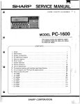
CE-t60lIl
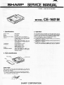
SERVICE MANUAL
SHARP
CODE
MODEL
1. Specifications
Product name:
Model:
Storage:
Power source for backup:
Celllife:
Temperature:
Dimensions:
Weight:
Accessories
supplied:
CE-1601 M
3. Operation
RAM module
CE-1601M
64 K-bytes
3V:7:(DC); lithium cell (CR2032) (1)
When module is in the computer: about
5 years; when not in the computer:
about 20 months.
(when kept at 20°C/68°F.
Life time
va ries depending on module usage and
environment.)
O°C to 40°C/32°F
to 1Q4°F
Height 8.5mm/(11/32")
Length 40.9mm/(1-5/8")
Width 42.8mm/(1-11/16")
15g (including the cell)
Case, cover labels (3), space cover,
lithium cell (inserted in the module),
operation manual.
The CE-1601M must be mounted in the PC-1600 memory slot S2.
If mounted in the memory slot S1, the computer may not perform
properly or data may not be written properly in the RAM module.
There are following four ways of using the RAM module.
A) The entire 64KB area used as a RAM file.
B) A 32KB area is used for a program memory and the remaining
32KB area for a RAM file.
C) A 32KB area is used for an expansion memory and the remaining
32KB area for a RAM file.
D) A 32KB area is used for a program memory and an expansion
memory, and the remaining 32KB area is used for a RAM file.
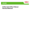
2. Parts identification
Protect switch
Terminal
cover
Protect switch
When the switch is set to the side marked with a ..... mark, the
RAM module is write prohibited so that the RAM contents may not
be erased and changed.
Wheo the switch is set at the other side, the write protect is released .
• To prevent incidental power off after the write protect is set, a
is attached to the switch area.
~
7~~
~
OOZCE1601MSME
Label
SHARP CORPORATION
CE-1601M
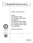
4. Module installation
Mode
1 A
f
Installation command
CD
To use the entire module as RAM file
TlTLE!
ENTER I
64KB RAM module
I
, Usersize
®
NEWO!ENTER!
61KB
[BecaOM the contents ofthe expansion
]:
(62,464B)
memory and data are all cleared, they must
be saved in another memory device if they
are to be used again.
®
B _{"KB'
....... ,...... ..... Proqrarn rnernory
[ BASIC test area ~
INIT"S2:",
J
C -{32KB
",,"
,,',
Expansion mernory
D
[EXpanSion
memory
f
t
r
I'
(j) INIT"S2,", "M"
1
®illffJ
29.5KB
I
48
(30,208B)
1
( [same value as the CE-1600 ]
is used for RAM file.
@ INIT"S2:",
t
Program memory
{'KB
i
@ INIT "S2:", "P" [§'ITgßJ
t
[EXpanSion memory ]
(SO) area increases
32.768 bytes more.
Rest of memory '" RAM file
'
"F"IENTERI
t
32.571 bytes
.
Reserve program area
= 189 bytes
Rest of memory ... RAM file
Directories
48
"P",
1'1.1 ENTER
~
~
I
t
r,
"n" represents the program
memory size. Ocld number
01 KBfrom 2to32 (32 - n) KB
represent the size 01
expansion rnemory,
f-
I
.
;
1
Rest of memory ... RAM file
NOTES:
oDelete all files using the KILL command.
oType TITLE "S2:" IENTERI NEW 0 IENTERI
(1) It is not possible to change the RAM module mode, if there is
data already existing in the module.
One of the following operations is required in order to change
the RAM module mode.
contents of progT~Rlemory.
o Type TITLE EN
NEW
the expansion memory.
(ffITEBJ
to clear the
to clear the contents of
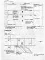
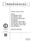
5. Memory map
(Map seen Irom the SC7852)
< Address)
[Bank ]
OOOOH
o
1
2
3
5
4
7
6
System
ROM
-
4000H
I
I
System
ROM
(S2:
I
System
ROM
)
I
!
I
8000H
PC-1600·'
kanji memory
COOOH
1.
,
PC-1600
memory
-,
............ -, ~
-.
"\.
Amo
slol
can
orexpan
ing ban
lor RA
8 bank
"-
-T
~ -,
System
ROM
ROM
16KBX
S2 .
SI:
NOTE:
*1, *2: Japan only
I
~'"
'.;..
...
....'\..~
-,
0
"'-
~~
-,
1
~
~""
~ =x
"\.
CE-1601M'\.,_
( 32KBX 2) '\.,_
'\..
~
"\.
3
~-4
'"
~
,,~
2
,,--
~
""
"'"
-5
~-6
~
ru
CE-1600M(32KB)
or CE-1620M
-------------
-2-
7
Vertica
bank
,ar:::n)'.f.2~
The vertical bank 01 S2 is selecled when
data 01 0 10 9 are written in 28H 01 Ihe 1/0
space. (Write only)
-
CE-1601M
6. Precautions
7. Service precautions
(1) When the computer is reset while accessing a file in this RAM
module, NEWO? may be displayed. Push the CL key to clear
the display. The contents 01 the main memory and RAM module
memory are still retained in this case.
(2) See the description below for the function of the write protect
switch.
(1) All parts must be closely attached on the PWB.
(2) Pin of the dip switch solde red must be cut not longer than 1.5mm
at a maximum.
(3) To check current, add 3VDC across battery terminal and diode
anode. It must be less than 9µA
DIPSW
Note
Function
Enables to write data
in the module.
·side
Disables to write data
in the module (ROM
module).
Above A) and B) are
permitted.
(3) To replace battery cell without connection of the AC adapter to
the PC-1600, the RAM module must be removed from the
PC-1600 if the RAM module is being used as a RAM file or
program file.
After replacing with fresh battery, all reset the PC-1600 before
mounting the RAM module.
Because program or data within the expansion memory are
cleared after replacing battery, the memory contents must be
saved on the floppy disk or cassette tape if it should be used
again.
8. Parts signal layout chart
DIP SW
t :From
-3-
'87 Feb. product, D43256G-12l
-
CE-1601M
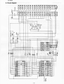
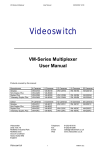
9. Circuit diaQram
~~;!
~
N
.,.
0
oe
u
.,.
r:
'"
~
-
~o ~:z ~...
CI:
~
~
~
~
~
~
~~ ~
~~
-
i~~
(/)M 4 ()..3:
g.
U"I~~
0
s:
1_~
.
I I I,
III
~
I
~
~
~
W
lSl
CI:
~
~
~
CI:
~ ~ ~~ IJJJ ~
laN~ v
l
ilMljjll
.g
LL
r-,
...J
-N
<Xlü~
-e ~ t
u:°eiil
Q.T""
-4-
-
CE-1601M
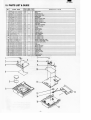
10. PARTS LIST & GUIDE
NO.
1
2
3
4
5
6
7
8
9
10
11
12
13
14
15
16
101
102
103
104
105
106
107
108
109
201
202
203
204
205
206
207
208
209
301
302
PARTS
CODE
HOECA100HCZZ
LX-BZ100HCZZ
HOECA1006ECZB
PZETL101JECZZ
PZETL100HCZZ
GCABB100JECZZ
PZETL1012ECZZ
QTANZ1002ECZZ
QTANZ1001ECZZ
PZETL10l0ECZZ
PSLOC10l0ECZZ
OUNTKI209ECZZ
P SHEP 1 0 1 1ECZ Z
M S P RC 1 2 0 2 C C Z Z
G C ABC 2 6 7 2 C C Z A
G C A BAI 0 0 4 E C Z Z
QSW-SI347CCZZ
RC-SZ1007CCZZ
VHOOAN202K/
1
VH01SS98///-1
VHiTC74HCI31F
VHi43256G-12L
VHi43256G-15L
VRS-TP2BOI02J
VRS-TP2B0564J
VSOTAI43XK/-l
GCASPI091CCZZ
GCASP1092CCZZ
GFTAUI281CCSA
PPACGIOOIECZZ
TCAUHI002ECZZ
TCAUZ100JECZZ
T iNSL1126ECZZ
TLABZ1690CCZZ
UKOG01009CCZZ
SPAKA7307CCZZ
SPAKC0265ECZZ
1
2
PRICE NEW
RANK MARK
AB
AA
AF
N
AA
AA
AC
AA
AB
AB
AA
AB
BR
N
AB
AC
AO
N
AF
AH
AF
AB
AO
AH
N
BO
N
BO
AA
AA
AB
N
AE
AO
AB
AE
AB
AE
AL
N
AA
AC
AC
AK
N
PART
RANK
0
C
0
C
C
0
C
C
C
C
C
E
C
C
0
0
B
C
B
B
B
B
B
C
C
B
C
C
0
C
C
C
0
0
C
0
0
DESCRIPTION
Switch_j)_anel
Screw
Panel(batterv lid)
Panel insulator sheel
BattID'_ sheet
Top cabinet
Battery_insulator sheet
Battery terminal 8
Battery terminal ~
Terminal insulator sheet
Shield_Qlate
RAM PWB unit(_64KB}_
Spring lixingsheet
Sorinl!
Terminal cover
Bottom cabinet
Slide switch
Caoacitor (ljlF)
Diode (OAN202K)
Oiode_l1SS91ll
IC (TC74HC 131F)
IC (43256G-12L)
IC (43256G 15L)
Resistor (1/8W lKO ±5%l
Resistor_(I/8W 560KO ±5_%1
Transistor _iOTA 143XISl
Case
Case cover
Reverse side cover
Module separater
Caution Card
Caution label
Instruction book
Switch cover label
Driver $
Packing cushion
Pacliirlg_case
~
~
1
3
4----<
o
5---V
15
-5-
-
CE-1601M
SHARP
COPYRIGHT
©
1987 BY SHARP CORPORATION
All rights reserved.
Printed in Japan.
No part of this publication
may be reproduced,
stored in a retrieval system, or transmitted,
in any form or by any means,
electronic, mechanical, photocopying,
without
recording, or otherwise,
prior written permission of the pubfisher.
SHARP CORPORATION
I nformation Systems Group
Quality & Reliability Control Center
Yamatokoriyama, Nara 639-11, Japan
1987 February Printed in Japan ®