1
The SG 631 LOGIC represents the utmost in tape recorder technology of today. As an aid
to you in familiarizing yourself with its new techniques, we are supplying highly detailed operating instructions and recommend that you read them carefully. If, however, you are already
very familiar with the operation of modern tape machines, you will simply need to read certain
sections. Each chapter forms a closed unit and refers, only when absolutely necessary, to
other parts of the manual, that, in turn, may be located easily by using the table of contents.
26
For full utilization of the new technologies offered by the SG 631, the points
below should befollowed carefully:
1.
Use UHER NAB Adapter Z 800 to avoid even the slightest play between reel and hub
shaft (see sec. 1.6).
2.
Use UHER "professional" metal reels (Z 827) as they guarantee smooth movement for
all tape transport functions and decrease tape wear (see sec. 6.10).
3.
UHER "professional" tape Z 830 is recommended for optimum operational results and
best electro-acoustical values (see sec. 6.10).
4.
Always use reels of the same size and of the same material together (see sec. 6.10).
5.
Make certain that the CUEING switch is set to "0" for all modes of operation except
CUEING to avoid tape spilling (see sec. 3.18).
6.
Make certain that the reel size switch is set to the appropritate position (see sec. 3.24).
7.
Read Chapter 7 "Care and Maintenance" with especial care.
8. When the SG 631 is operating in the fast-wind mode, for safety reasons neither move
it from horizontal to vertical operating position nor touch the reels under any condition.
9.
At the end of the Operating Instructions you will find a list of UHER accessory equipment
available from your UHER dealer to supplement your recording system.
27
Contents
28
29
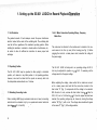
1. Setting up the SG 631 LOGIC for Record Playback Operation
1.1 Air Circulation
The greatest amount of heat develops around the power transformer
which is located at the center of the ventilating slits. The ventilating slits
must be left free regardless of the machine's operating position. When
installing the machine in a cabinet, a closed section of wall shelves, etc.,
be certain to allow for sufficient air circulation to assure proper heat
exchange.
1.2 Operating Position
The SG 631 LOGIC may be operated in either upright or horizontal
position, or if desired, in any tilted position. In all operating positions,
however, care must be taken that the spools are securely held onto
the hub spindles as described in sec. 1.6 below.
1.3 Extending Connecting Leads
When matching UHER plug-in extension leads are not used, connecting
leads should be extended only by an experienced service technician
(see also sees. 2.3, 2.4 and 2.5).
, "
'-
30
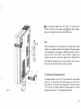
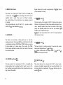
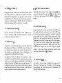
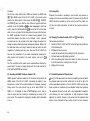
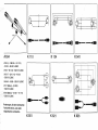
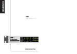
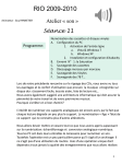
1.4 A.C. Mains Connection, Operating Voltage, Frequency,
Mains Fuse
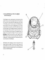
The mains lead is attached to the machine and is located in the covered recess in the floor (or rear) of the housing (see Fig. 1). Before
plugging the lead into a mains power outlet, ascertain the voltage of
the power supply.
The SG 631 LOGIC is factory-set to an operating voltage of 220 V,
but may be adjusted to operate on 115 V A.C. If necessary, set the
voltage selector to the proper voltage.
Before adjusting the voltage, make certain that no leads are connected to a mains power outlet and that the mains fuse, located in the
fuse holder "A" (Fig. 1) corresponds with the voltage to be selected.
With the aid of a coin, unscrew the fuse holder. Use a 0.8 A fuse for
220 V A.C., and a 1.6 A fuse for 115 V. Once the proper fuse has been
inserted, the operating voltage may be chosen by turning the voltage
selector "B" (Fig. 1) with a coin. The voltage value selected will appear
in the recess "C" (Fig. 1) of the voltage selector.
It is not necessary to adjust the SG 631 LOGIC to a mains frequency
of 50 Hz or 60 Hz as the machine uses D.C. motors and the power
supply unit is designed for operation with either frequency.
Note:
Extreme overloading of the power supply unit or internal short-circuiting
activates an automatic guard circuit that switches off the power supply
unit. Disengaging then re-engaging the POWER push-button returns the
guard circuit to its "alert" function. Fuses for the D.C. voltages in the
machine may also burn out when the guard circuit is activated. Such
fuses should be replaced only by a service technician as the cause of
the blow-out must be detected and, if necessary, removed.
1.5 Mounting Feet for Upright Operation
Fig. 1
For upright operation, two feet "D" are provided with each machine
(see Fig. 1). To mount them, first lay the machine on one side. Turn
fixing screws "E" a few times into the threadings "F". Next push notches
"G" in the feet "D" under the head of the fixing screws "E" until the
bridge catches in groove " I " . Then tighten fixing screws "E".
31
h
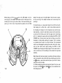
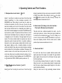
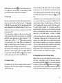
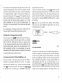
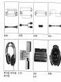
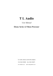
1.6 Mounting UHER NAB Adapter Z 800 for 26.5 cm (10%")
Reels and Loading Tape
The NAB adapter must be carefully placed on the right and/or left hub
spindle. First, pull up the three-pronged mandrel (A) of the spindle (see
Fig. 2) and turn it until the prongs of the movable section rest on those
of the stationary section. The inner ring (B) of the NAB adapter must
also be turned to the left until the clamping jaws (C) for the threepronged mandrel (A) are opened so wide that the adapter may be easily
set upon the spindle. Once the adapter has been set in place (see Fig. 3),
the three-pronged mandrel (A) should be turned to the right or to the
left until it jumps down into the grooves of the stationary setion. The
adapter is then prevented from falling off. The inner ring (B) of the
clamping jaws should then be turned to the right, closing it until the
adapter is tightly secured to the three-pronged mandrel. Tightening the
clamping jaws is of particular importance as it will prevent any play between the mandrel and the NAB adapter.
NAB adapters without clamping jaws cannot do away with the play
between mandrel and adapter. If the play is too great, however, poor
speed stability and poor tape wind may result. (Mounting such NAB
adapters and securing them against falling off is best accomplished as
described for UHER NAB adapters.)
32
Fig. 2
Before placing a 26.5 cm (IOV2") reel on the NAB adapter, turn the
outer ring (D) of the adapter anti-clockwise until the three keys of the
movable part of the ring are above those of the lower stationary part
(see Fig. 2). The full reel of tape should be placed on the left NAB
Fig. 3
adapter, the empty reel on the right adapter. Once the reel is in place,
turn the outer ring of the adapter clockwise until a clear stop is felt
(see Fig. 3).
To thread the tape, run a tape lead of about 50 cm (20") from the lefthand (supply) reel - without slack - past the tape tension sensor into
the threading slot between the front tape-head cover and the tapehead assembly, out past the right tension sensor onto the right (takeup) reel and turn the take-up reel until the supply reel is turned along
with it. On pressing the power switch and actuating the START or FAST
FORWARD key, the tape lead will wind onto the take-up reel until the
transparent or metal-coated switching foil appears. The foil activates
an automatic shut-off switch for all deck functions. The foil-activated
switch may be disengaged by pressing the counter reset button; hence,
with the reset button down, lightly touching the START or FAST
FORWARD key will begin tape transport again. The zero reset button ©
must be held down until the switching foil has cleared the tape head
assembly.
Note: Tapes which have been played or recorded on other tape machines
must be inspected to make certain that they are tightly wound onto the
reel. If necessary, unwind and rewind the tapes on your SG 631 before
using them to record or replay.
,
To facilitate loading tape when small sized reels (under 18 cm) are used,
first press the PAUSE @ and CUEING @ keys; then deactivate them
after loading tape on it.
33
*
•
'
1.7 Record Operation for Users in a Hurry
As the quality of the recording is essentially dependent upon the correct
setting of the record level, this step should be given particular attention:
6.
Press the zero reset button of the counter to mark the beginning
of the recording.
1.
Make certain that the input source to be used in recording is
connected and switched on.
7.
Using the master control (5) , fade in the desired input sources
(see sec. 3.3).
2.
Press POWER switch © (Check connection to mains power outlet).
Function indicator above STOP key must light up.
8.
Using level controls © to © , set maximal record level for loudest
passages to be recorded (see sees. 3.1 and 3.2).
3.
Load tape and wind past switching foil onto take-up spool (see sees.
1.6 and 3.15).
9.
Press LIMITER switch © and check setting for correct (maximal)
record level (see sec. 3.5).
4. Set a) tape type switch @ for tape used (see sec. 3.21),
b) reel size switch @ (see sec. 3.24),
c) mode selector switch (8) to desired record mode (see sec. 3.6)
and
d) tape speed selector ® (see sec. 3.8).
5.
34
Touching them lightly, one after another, actuate the RECORD®,
PAUSE @ and START (J3) keys. The function indicators above the
keys will light up.
10. Tip PAUSE k e y © once more. Tape transport and recording will
begin. Tipping the PAUSE key still again will interrupt tape motion
and recording.
11. Connect stereo headphones (see sec. 2.2) and adjust their volume,
using headphone volume control @ . Check recording acoustically
(as described in sec. 3.7) by pressing the MONITOR switch (9)
12. Lightly tipping the STOP key © ends record operation.
13. To switch the recorder off, press the POWER switch © .
1.8 Playback Operation for Users in a Hurry
Playback may be directly through the machine's headphones power
stage (which permits connection of two stereo headphones) or through
the loudspeakers of your hi-fi sound system.
Procedure:
1.
2.
3.
4.
Set a) tape type switch @ for tape used (see sec. 3.21),
b) reel size switch @ (see sec. 3.24),
c) mode selector switch (f) to desired playback mode (see sec. 3.6)
and
d) tape speed selector ® (see sec. 3.8).
5.
Lightly tip START key ® . The function indicator above the key should
light up, and tape transport should begin as soon as the OMEGA loop
is formed.
6.
Set volume as desired for headphones via headphones volume
control © , for loudspeakers via volume controls on the power amplifier of the hi-fi sound system.
7.
When playback is through the sound system amplifier, correct tone
and balance settings, if needed.
8.
If necessary, set MONITOR switch (9) in off-TAPE position.
Make certain that the amplifier connected for playback through the
sound system speakers is switched on - or that the headphones
are connected (see sees. 2.2, 2.4 and 2.7).
Switch on recorder by pressing POWER button © . The function indicator above the STOP key © must light up.
Load tape reels and lock. Thread tape and wind onto take-up reel
past switching foil (see sees. 1.6 and 3.15).
35
2. Socketry
Data on pin wiring as well as input/output sensitivities and impedances
are supplied as an aid to the technician (e.g., in constructing special
connecting leads) to assure optimum matching with input sources and
playback equipment.
2.1 MICROPHONE ©
All commercially available low-impedance dynamic stereo microphones
(200 to 500 ohms) equipped with DIN plugs may be directly connected
to this socket. For stereo recording with two mono microphones, UHER
Adapter Lead K 626 should be used. Care must be taken that the plug
of the adapter is inserted into the socket fully up to the stop.
UHER K 110 is the extension lead for use with low-impedance mono
microphones, K 134 for use with stereo microphones (see list of accessories at the end of the Operating Instructions).
UHER dynamic stereo microphone M 641 and UHER electret condenser
microphone M 646 may be directly connected. Their earlier models M 640
and M 645, on the other hand, require UHER Adapter K 822 for connection.
Input signals at pins 3/2 and 5/2 (2 = ground) should be between 0.1 mV
and 80 mV. All commercially available condenser microphones with
(DIN 45326) 8-pin plug may be connected to this socket. The plus pole
of the microphone power supply ( + 20 V, source impedance 1.2 kohms)
is located at pin 8.
36
2.2 HEADPHONES (5-Pin) <^>
This socket is for connecting a stereo headphone set equipped with
a 5-pin plug (like UHER W 775) for monitoring record or playback. All
high or low impedance headphones currently available on the market
may be connected (output impedance 8 to 2,000 ohms). UHER Adapter
K 633 must be used when connecting headphones with two LS-7 plugs
(like UHER W 774).
When listening to playback, the MONITOR switch ® should be in offtape (TAPE) position and the volume regulated with the headphones
volume control d?) .
2.3 HEADPHONES (Phone Jack) <®>
This facility is for connecting a stereo headphone set equipped with
a jack plug. All high or low impedance headphones currently available
on the market may be connected (output impedance 8 to 2,000 ohms).
When listening to playback, the MONITOR switch ® should be in offtape (TAPE) position and the volume regulated with the headphones
volume control (f?) .
2.4 DUBBING Output QO
This socket is for convenient tape copying onto a second open-reei
or cassette tape recorder. Using UHER Stereo Connecting Lead K 541,
connect this DUBBING socket to the RADIO socket of the recording
tape machine. Output signals delivered to pins 3/2 and /2 (2 = ground)
are approximately 750 mV (output impedance less than 15 kohms).
2.5 RADIO Input/Output | j
This socket is a combined input and output for connection to a stereo
tuner or receiver with DIN standard sockets. For record or playback use
UHER inter-unit Stereo Lead K 541 to connect the SG 631 LOGIC to
the TAPE socket of the tuner or receiver.
With mono equipment, UHER Adapter K 837 must be inserted into the
TAPE socket of the mono set before using the K 541 lead to make
connection to the SG 631 LOGIC.
To avoid loss of response in the high frequency range during record
and playback, the connecting lead (K 541) should be extended only
by a service technician, and then only if the output impedance of the
input source or the input impedance of the playback equipment permits. Input signals at pins 1/2 and 4/2 (2 = ground) of this socket may
be between 1 mV and 200 mV (input impedance 27 kohms). For input voltages over 250 mV, it is advisable to use the PHONO input socket.
Output signals delivered to pins 3/2 and 5/2 (2 = ground) are approximately 750 mV (output impedance maximum 15 kohms).
2.6 PHONO Input ©
This socket is Tor connecting stereo record players with DIN plugs and
crystal pickup cartridges. Record players with magnetic pickup must be
equipped with their own equalizing amplifier. High-impedance equipment (e.g. stereo tape or cassette recorders, stereo receivers or UHER
mixer Mix 500 A 124) may also be connected to this socket, using UHER
Stereo Lead K 541.
Input signals at pins 3/2 and 5/2 (2 = ground) may be between 80 mV
and 10 V (input impedance 680 kohms).
2.7 DIA (Slide) ^
This socket is for connecting automatic slide projectors via UHER Projector Lead K 911. Pins 2 and 3 are for slide changing by signalling
the "Dia-Pilot" of the SG 631 LOGIC to scan the 1 kHz pulses recorded
on the tape. The "Dia" tape head run-out to pins 4 and 6 (6 = ground)
permits control of multi-vision projectors that operate with pulses up
to 7 kHz. In addition, this tape head is also for record and playback
of the pulses responsible for synchronizing tape recorder and projector
in 8 mm and 16 mm film dubbing.
37
2.8 MONITOR 5-Pin Output
• - . ' • *
This socket is for connecting the SG 631 LOGIC to an amplifier with
a monitor input, using UHER Stereo Connecting Lead K 541. Use the
amplifier's switch to select "from source" or "off-tape" monitoring.
Give careful attention to the instructions in the operating manual of
the amplifier.
Output signals delivered to pins 3/2 and 5/2 (2 = ground) are approximately 750 mV (output impedance 15 kohms).
2.9 ACCESSORY A
This socket is for connecting a starting switch (see sec. 6.9) when
operating with a timer. When using UHER Timer A 403, the SG 631 LOGIC
is automatically switched to RECORD and START functions as soon as
the timer switches on the power supply of the recorder. The PAUSE
function may be switched by remote control if pins 3 and 4 of this socket
are connected together.
2.10 MONITOR Jack Output | l R
This stereo output is for connecting the SG 631 to an amplifier with
monitor switching. Use the amplifier's switch to select "source" or "offtape" monitoring, paying careful attention to the instructions in the operating manual of the amplifier.
38
Signals delivered to this output are approximately 750 mV per channel
(output impedance 15 kohms).
2.11 INPUT 2 (Jack) f i
' '.
This stereo input is for connecting the SG 631 to high-level input sources
like stereo record players with crystal pickup systems, stereo tape (openreel or cassette) recorders, stereo tuners or receivers. Stereo record
players with magnetic pickups must have their own equalizing preamplifier to be connected to this input.
Input signals may range between 80 mV and 10 V (input impedance
680 kohms per channel).
2.12 INPUT 1 (Jack) | i
•
This stereo input is for making connection to low-level input sources
having output voltages between 1 mV and 200 mV.
Input signals at these jacks may range between 1 mV and 200 mV
(impedance 27 kohms per channel).
2.13 OUTPUT (Jack)
®R
These stereo jacks are for connecting the SG 631 to stereo tuners,
receivers and amplifiers equipped with jack connecting facilities. Output signal strength is approximately 750 mV per channel (output impedance 15 kohms).
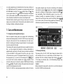
3. Operating Controls and Their Functions
3.1 Microphone Record Level Controls L 0 and R ©
Knobs © 1 and (2) are for setting the record level of the left and right
channels (respectively) of a stereo microphone connected to the
MICROPHONE input. When setting the record level, the master control ©should be pushed to the left all the way to the stop, the peak
level limiter remaining out of circuit for the moment. The correct record
level has been achieved when the corresponding level indicator registers 0 dB at the loudest passages to be recorded. The LIMITER switch (7)
may then also be pressed. The peak level limiter will thus be in circuit
and will prevent overloading the tape by reducing the record signal to
a manageable level for the duration of the signal peaks that may be
incurred. The function indicator beside the respective level meter will
always light up when the peak level limiter is in operation. Lighting up
briefly and in not too rapid succession indicates that the limiter is operating properly. Lighting up often or constantly indicates an incorrect
record level setting that may easily occur during microphone recordings
when the distance from the microphone is decreased. The degree of the
overload is shown on the record level meter (see also sec. 3.4). The
record level setting may be acoustically checked by making a test recording and monitoring through headphones with the MONITOR button (9) switched from TAPE to SOURCE position (see also sec. 3.7).
3.2 Radio/Phono Record Level Controls L (3) and R ©
Knobs (5) and © are for setting the record level of the left and right
channels (respectively) of stereo input sources connected to the RADIO
or PHONO input sockets. When setting the record level, the master
control (D should be pushed to the right all the way to the stop. The
remaining procedure is as described in sec. 3.1.
3.3 Master Control (5) for Fading in, Out or Over from Radio/
Phono Inputs to Microphone Input during Record
This slide control has a middle click-position from which - once the
record level has been set - radio or phono inputs may be blended over
to record from the microphone (see sees. 3.1 and 3.2). Fading in, out
or over of all input sources connected and switched on may be continuous and completely click-free. With the master control in middle
position all input sources are switched out of circuit.
3.4 Record Level Meter ©
The record level meter has two separate indicator systems which
register peak values for the signal to be recorded. The upper indicator
system registers the record level of the left channel, the lower system
that of the right channel.
The record setting decisively influences the quality of the recording.
Setting the level too low (under-recording) impairs the signal-to-noise
ratio that may be achieved because signal strength will not be able to
cover the tape hiss sufficiently.
Setting the record level too high (overloading) increases harmonic
39
distortion and leads to playback that sounds too shrill and distorted.
The maximal harmonic distortion permissible is 3% and is reached when
the level meter reads 0 dB with the machine set for full record level
(using DIN reference tape). With the maximal record level above 0 dB,
distortion rises far above 3% and rapidly sinks to 1% or less with the
maximal record level below 0 dB.
Each level registering system is equipped with an illuminated indicator
that functions when the peak limiter is switched in circuit (see also sec.
3.5). Although the function indicators of the peak limiter are signalled
parallel to the level indicators, it is possible that with the limiter in-circuit
its. function indicators may light up at brief signal peaks even if the level
meter does not yet register 0 dB - because the level indicating systems
are slightly sluggish due to the mass that must be moved. When setting
the record level without using the limiter, however, this effect has no
influence upon the quality of the recording as the response time of the
level meter is sufficiently brief. (Even the light exposure meters used in
commercial sound studios are "much" slower than the illuminated
function indicators which operate inertialessly.)
Aside from optical control by means of the record level meter, an
acoustical check may be made during record with the aid of the monitor switch (see sec. 3.7). Even during playback the two separate indicator systems of the level meter register the peak values of the signals recorded on the tape.
3.5 LIMITER Switch ®
The LIMITER button catches in down-position and switches on the peaklimiting circuit that, when the record level is too high (pointer in red
field of meter), reduces the record signal to a manageable level for the
40
duration of the overloading. The degree of overloading is shown on the
level meter while the two function indicators, located next to their respective level indicating system, reflect the functioning of the limiter by
lighting up for a relatively long or short period. Optimal record level has
been set when one of the illuminated indicators flickers up only
occasionally. Otherwise the record level must be lowered, using the
appropriate level control. When the limiter switches on and off in rapid
succession due to an incorrect record level setting, it creates a
"pumping" or "breathing" effect that becomes noticeable through a
swelling and receding of the background noise.
Pressing the LIMITER switch ® a second time releases it into its upposition and switches off the peak level limiting circuit.
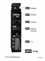
3.6 Mode Selector ®
Turning this switch sets the SG 631 LOGIC into MONO, STEREO or
SLIDE operating mode. In quarter-track operation (using Tape Head
Assembly Z 412), switching to MONO 1 position sets the machine for
operation on track 1 or track 4. In half-track operation (using Tape
Head Assembly Z 402) MONO 1 position switches to track 1. Always
use level control © or (3) to set the mono record level that in turn, will
be registered by the upper indicator of the level meter. Similarly, with
the switch in MONO 2 position, track 2 or track 4 will be used in quartertrack operation and track 2 in half-track operation, with level controls CD
or (3) used for setting the record level. The record level for MONO 2
operation, however, is registered by the lower indicating system of the
level meter. During mono operation the level controls (2) and @ are not
needed and should be faded out.
With this switch in MONO 1, MONO 2 or STEREO (quarter-track stereo
operation using Tape Head Assembly Z 412) the full take-up reel may
be exchanged with the empty supply reel for a second tape pass after
the first pass has been completed and tape is completely on the right
(or take-up) reel. In half-track stereo operation only one tape pass is
possible; hence the tape should be rewound onto the left (or supply)
reel once the tape is completely on the take-up reel.
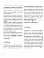
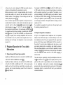
In half-track operation slide synchronization may be only monophonic,
but stereophonic in quarter-track operation. The differences between
half-track and quarter-track operation as well as the location of the
control track for slide projector operation are clearly shown in Fig. 4.
Slide synchronization is possible only at the 9.5 or 19 cm/s {7W or 33A")
tape speeds!
3.7 MONITOR Switch ©
This pushbutton is for selecting "off-the-tape" ("B") or "from source" ("A")
as the mode of monitoring during record. It allows the quality of the
recording to be checked acoustically at once, during record, for in "B"
position playback of the signal just recorded is directly off the tape. On
the other hand, with "A" monitoring the signal delivered by the input
source may be heard while it is being recorded on the tape. This direct
comparison of source and tape recording lets differences between the
two be easily recognized.
When the switch is in TAPE position, a green function indicator
lights up while a red illuminated function indicator reflects the
SOURCE monitoring position. Both function indicators are located above
the MONITOR switch.
3.8 Tape Speed Selector ®
Turning this switch sets the tape speed at (4.7, 9.5 or 19 cm/s) 1Vs, 33A,
7V2 ips. As may be seen in the Performing Specifications at the end of the
Operating Instructions, the highest quality demands are fulfilled at the
71/2 speed. Note: Operation of automatic slide projectors and multivision projectors is possible only at tape speeds 3% or 7V2 ips.
3.9 REC(ORD)Key ©
Fig. 4
Pressing this key lightly sets the SG 631 LOGIC in record mode, and
setting the record level may be undertaken at once. Make certain that
the tape type selector is in the proper position (see also sec. 3.21).
41
When the RECORD key is engaged, the function indicator above it is
lighted. Actual start of recording is begun by lightly pressing the START
key (13) .
With the REEL-SIZE switch @ in its neutral up-position the SG 631
LOGIC is set for (27 cm) IOV2 spools. If tape on (13-18 cm) 5"-7" spools
is used, press the REEL-SIZE switch into its down-position. The proper
green function indicator above the switch lights up to show which reel
size has been selected and set.
The green function indicator above the PAUSE key lights up when the
key is engaged.
3.13 STOP Key ©
Lightly pressing-the STOP key disengages all deck functions described
above. As long as the STOP key is engaged, the green function indicator above it will remain lighted.
3.10 Rewind
Pressing this key lightly sets the machine for fast rewind. It may be
activated directly from any other operating function setting. When the
REWIND switch is operation, the green function indicator above it
lights up.
3.14 Fast Forward Key © • •
Lightly pressing this key switches the SG 631 LOGIC to fast forward
wind. It may be actuated directly from any other deck function setting.
When the switch is engaged, the green function indicator above it
lights up.
3.11 START Key ®
On lightly pressing the START key, the tape is formed into an OMEGA
loop around the capstan, whereupon tape transport begins. The START
key may be actuated directly from any other operating function setting.
When the switch is engaged, the green function indicator above it
lights up.
3.12 PAUSE K e y ®
Pressing this key lightly interrupts tape motion begun with actuation of
the START key. Tipping the key a second time re-starts tape motion.
42
3.15 Counter with Zero Reset Button /Off-Switch for
Automatic Shut-Off ©
Pressing the zero reset button cancels any given index number, returning the counter reading to "0000". Before each recording, it is
advisable to press the reset button or note the starting index number.
Holding the button down switches off the automatic shut-off circuit
that is normally actuated by the foil (transparent or metal) at the beginning or end of the tape. Then upon pressing one of the tape transport keys, the switching foil will move away from the switch-off contacts
or light barriers.
3.16 POWER On /Off Switch
3.19 "DIA" (Slide Control Pulse) Button ©
Pressing this lock-down pushbutton into down-position switches on the
power supply of the SG 631 LOGIC. The level meter and the function
indicator above the STOP key will then light up, as well as one of the
two MONITOR function indicators and one of the function indicators for
the reel-size switch. Pressing the POWER button once more switches
off the power supply, and the button will return to its up-position.
Pressing this button will record a slide-changing pulse (1 .kHz) on the
control track of the tape if the mode selector (§) is set to DIA (to switch
on the control signal generator) and the RECORD key @ has been
actuated.
3.20 OUTPUT LEVEL Control @
3.17 Headphones Volume Control ©
This knob is for linear volume regulation of stereo headphones connected to the SG 631 LOGIC. Turn the knob clockwise to increase
the volume, anti-clockwise to decrease it.
3.18 CUEING Switch ®
"Cueing" in the sense of "giving the signal or key-word to begin" gives
the best idea of what happens in the CUEING process. A certain spot
on a recorded tape is located in order to begin a new recording or to
begin playback of a particular passage, or to edit (splice) tape: as is
everyday practice in professional studio recording.
The approximate location of a particular spot on the tape can be accomplished by using the fast-forward or rewind modes plus the index
counter. For exact location, however, switch the SG 631 to PAUSE and
playback, then activate the CUEING switch (turn switch to position 1);
the tape reels may then be turned by hand. Slowly turning the take-up
reel with one hand while slightly braking the supply reel with the other
permits the playback to be heard at relatively normal pitch.
Turning this switch sets the output signal delivered to the RADIO socket
and permits matching the output level of the SG 631 LOGIC to that
of a second sound source when connected to an amplifier not equipped
with a variable input level control. With the volume control of the
amplifier in the same position when switching from tape playback to,
for example, phono playback, the volume level should remain unchanged.
With the output level control in middle position, an output signal of
750 mV per channel is delivered to the RADIO output socket. Turning
the level control clockwise raises the output voltage (up to approximately 1.2 V per channel). Turning it anti-clockwise lowers the output
signal (down to approximately 500 mV per channel).
3.21 TAPE SELECT Switch
Turn switch to set the machine to standard ferric oxide tape (Feposition) or to ferrichrome tape (FeCr-position). The latter has two
magnetic coatings and a high frequency output of approximately 4 dB
better than that of standard tape.
43
3.22 Stroboscope Discs 50 Hz @ and 60 Hz @
fc
The 50 Hz stroboscope disc is incorporated into the tape tension sensor of the supply reel while the 60 Hz disc is on the sensor of the
take-up reel. Under artificial light and at a mains frequency of 50 Hz,
the line segments on the left stroboscope disc will appear to be standing
still if tape motion is at the exact speed of 71/2 ips. The line segments
will seem to rotate slowly if the tape speed is slightly inaccurate. The
same holds true for the stroboscope disc on the right tape tension
sensor (of the take-up reel) at 60 Hz and under artificial light.
The stroboscope is a highly precise indicator that permits recognition
of the very least deviation from the nominal tape speed. Very slight
stroboscopic deviations are, therefore, of no practical significance.
When the stroboscope seems to turn anti-clockwise, tape speed is toe
high; when it seems to turn clockwise, the speed is low.
may be taken into consideration. With the fine control in "0" position,
the 71/2-ips speed will be within the margin of tolerance permitted by
German DIN standard 45500.
3.24 Reel-Size Switch
When using reels up to 7" in size, press this pushbutton into
lower, locking position. The green function indicator "5-7" will light
If two IOV2" reels are used, the switch should be set to "IOV2". It
then be in its up-position and the green function indicator "IOV2"
light up. (Always use two reels of the same size!)
its
up.
will
will
4. Record Operation for True Audio
Enthusiasts
3.23 Find Speed Ajuster (7Vz ips) / Pitch Control @
When the tape speed selector set to 19 cm/s, this control may be used
to adjust the speed by approximately +4%. The pitch of the recording will
thus also be altered by ±4%. In general, it is necessary and advisable to
alter the tape speed only when playing tapes recorded on other machines
or when, for example, the pitch of a recording made with your SG 631
must be adjusted to that of a musical instrument. As a matter of principle, of course, recordings on your SG 631 should be made at the
nominal speed. Consequently, after altering the tape speed, do not forget to reset the speed to exactly 19 cm/s (71/2 ips), using the stroboscope to assure accuracy. Fine speed adjustment should be made only
after the machine has warmed up (allow at least 10 minutes after switching the power on) so that any slight drift during the warming-up period
44
4.1 Input and Output Connections
Input and output devices should be connected as described in sees.
2.1, 2.5 and 2.6 (or 2.11 and 2.12). If, while seeking the correct setting
for maximal record level of an input source connected to the RADIO
input, it is found that the level controls (3) and 0 must be kept just
barely opened in the lowest part of the scale range, check whether connecting the input source to the PHONO input would lead to better
recording conditions. Contact assignment and input impedances would
have to be taken into consideration, and a crossover adapter (pin 1 is
cross-connected with pin 3, pin 4 with pin 5), obtainable from your audio
dealer, would have to be inserted into the PHONO socket. The procedure is conversely similar when input sources are connected to the
PHONO input and level controls (D and © must be kept turned up full
in the highest part of the scale range. If you have difficulty in solving
such connecting problems, kindly consult your audio dealer.
4.2 Power Supply
When first connecting the SG 631 LOGIC, particular attention should be
given to the instructions and comments found in sec. 1.4. Never forget
to disconnect the power supply lead from the mains power outlet
before changing the fuse or resetting the voltage. The plug must also
be taken out of the mains outlet before cleaning the SG 631 LOGIC
with a moistened cloth.
If the power supply is completely in order, the level meter and the
function indicator above the STOP key must light up once the POWER
switch (18) is pressed. In addition, the function indicators for "A" or "B"
monitoring and for reel-size "5-7" or "IOV2" must light up, according
to the control settings. The D.C. fuses, which are not accessible from
outside the machine's housing, should be changed only by a service
technician as the cause of the defect must first be removed.
Even extremely brief overloading and internal short-circuiting are
detected by an electronic guard circuit that immediately switches off
the power supply. Pressing the POWER button (j§) off and on again will
switch the power supply back on if the D.C. fuses are still intact.
4.3 Preparing to Record
All preparatory steps prior to actual recording should be carried out
with great care. They will be easier to remember if they are always executed in the same order.
After first mounting the NAB adapters and/or the reels, then threading
the tape (see sec. 1.6), make certain that the reels are securely locked
onto the spindles and that the right switches for tape type (switch @ )
and reel-size (switch @) have been activated (see also sees. 3.21 and
3.24).
In selecting the tape speed, the frequency response of the input source
to be used and, under certain circumstances, the duration of the recording, should be decisive. The highest frequency an FM station can
transmit is 15 kHz. In reality, however, broadcasts rarely exceed 12.5 kHz.
The highest frequency obtainable from a high-quality microphone is
approximately 20 kHz. The same is true of new, high-quality phonograph
records. As speed deviations between two tape recorders may be
balanced out - but also added together - in dubbing, it is advisable
to set the recording machine at the highest tape speed whenever possible.
The advantages of doubling tape use or of stereophonic sound, for slide
showings or film dubbing, which may be achieved through quartertrack recording are juxtaposed by an improvement of approximately
3 dB in the signal-to-noise ratio and the possibility of editing (splicing)
the tape when recording with the half-track stereo configuration.
Before starting to record, careful thought should given to all of these
factors and, if necessary, test recordings made for evaluation.
4.4 Making Record Level Test and Starting to Record
Making a record level test means adjusting the record level - without
tape motion - before starting to record. The test can be made upon
simply pressing the RECORD key (ri) lightly. A more practical procedure
is, however, to actuate the RECORD © , PAUSE © and START ® keys
one after the other once the tape has been threaded and wound onto
the take-up reel past the switching foil (see sec. 1.6). The SG 631 LOGIC
45
is then set up to record, releasing the PAUSE key permits actual recording to start immediately after completing the level test.
Before commencing to record, it is always advisable either to note the
counter index number or to press the zero reset button in order to
facilitate location of the beginning of the recording upon later tape
rewind or playback (see sec. 3.18).
Once all of these steps have been completed, the input source to be
recorded should be faded in via the master control (5) and, using level
controls© and ® or (3) and 0 .adjusted for maximal record level at the
loudest passages (see sees. 3.1 to 3.4). The peak level limiter © may
then be switched in-circuit (see sec. 3.5), and releasing the PAUSE key ®
(to up-position) will start actual recording. By switching the MONITOR
switch ® (see sec. 3.7) from TAPE to SOURCE, you may also acoustically judge the quality of the recording. Headphones must be connected as described in sec. 22 (for their volume regulation see 3.17), or
monitoring must be through the loudspeakers of your sound system
(see sec. 5.1).
5. Playback Operation for True Audio
Enthusiasts
5.1 Playback through Hi-Fi Sound System Amplifier
Amplifiers with DIN socketry should be connected to the RADIO socket
of the SG 631 LOGIC via UHER Stereo Lead K 541.
Amplifiers with phone sockets may be connected to the RADIO socket
of the SG 631 LOGIC via UHER Lead K 551. On the sound system
amplifier use the left and right tape inputs. Before connecting up the
equipment, note the lead end markings: yellow for the left channel, red
for the right channel.
46
For playback the MONITOR switch ® on the SG 631 LOGIC must be
in TAPE position. Set volume, tone and channel balance in accordance
with the operating instructions for your amplifier. The playback (or output) signal delivered to the RADIO socket may be raised or lowered
by turning the OUTPUT LEVEL control @ . Thus the tape recorder signal may be adjusted to permit switching to other input devices (like
a record player) connected to the amplifier without a change in volume
(see also sec. 3.20).
If your amplifier is equipped with a monitor input, the input may be used
for monitoring as described in sec. 6.2.
5.2 Playback through Stereo Headphones
All high or low impedance stereo headphones with an impedance
between 8 and 2,000 ohms may be connected directly to one of the
two headphones sockets if they are equipped with 5-pin plugs. Headphones with LS-7 plugs require UHER Adapter K 633 for connection to
the sockets. To connect stereo headphones with jack plugs, you will
need special adapters which are available at audio dealers' everywhere.
When using these adapters, you may find that the playback of a stereo
recording is monophonic. In such case, pull the 5-pin plug of the adapter
out of the headphones socket and turn it 180° before re-plugging it
into the socket.
The volume may be regulated by turning the headphones volume control © as described in sec. 3.17. The output signal (which may be adjusted with this control to approximately 1.5 V per channel) delivered
to the headphones socket permits connecting self-energized loudspeakers which achieve particularly high acoustic output. Self-energized
loudspeakers should be connected the first time by your audio dealer
or an audio technician.
6. Further Hints and Tips
6.1 Transcribing onto Another Tape Recorder (Dubbing)
Without having to alter stationary connections to your sound system,
recordings may be copied onto another open-reel (or cassette) recorder by using the DUBBING socket. UHER Stereo Lead K 541 should
be used to connect the SG 631 LOGIC to the RADIO socket of the other
recorder. (The output level control @ does not affect the dubbing
output.)
6.2 Monitoring via the MONITOR Output
If the power amplifier of your sound system has a monitor input, you may
use the system's loudspeakers for acoustic monitoring of your recording
by connecting the MONITOR socket of the SG 631 LOGIC to the MONITOR input of the amplifier (UHER Stereo Lead K 541 will be needed).
Switching for off-tape or from-source monitoring may be accomplished
either from the tape recorder or from the amplifier. When switching from
the tape recorder, the monitor switch of the amplifier must be pre-set
for off-tape monitoring. On the other hand, to use the amplifier's switch
to select the mode of monitoring, the monitor switch of the SG 631 LOGIC
must be in TAPE position.
6.3 Sound for Slide Shows
Sound for a slide show and the control pulses that trigger slide change
should be recorded separately. When working with the half-track tape
head assembly (Z 401), only monophonic recording is possible as the
control pulses must be recorded on the lower track (see Fig. 4 "SLIDE +
MONO") of the tape. Moreover, during playback through the power
amplifier of a hi-fi system the volume of the control track channel must
be turned down to zero in order to render the 1 kHz control pulses
inaudible. On the other hand, if the quarter-track tape heads (Mount
Z 411) are used, sound for the slide showing may be stereophonic (see
Fig. 4 "SLIDE + STEREO"). It should be noted that only tape speeds 3%
or 71/2 ips may be used for recording the sound and control tracks for
slide shows. Before starting to record, write a script detailing the order
in which the slides are to be shown together with the commenting texts
and the background music to be employed. Referring to the script, you
may use the master control (5) , when recording, to fade in and out
the microphone input for the spoken comments and the radio or phono
input for the musical background. To fade over from the microphone
input to the radio or phono input, evenly turn the level of the microphone
input down to zero (the mid-position of the master control) and evenly
increase the level of the music input from zero to the full strength desired. If the spoken commentary is to be accompanied by a soft musical
background, a mixer (like UHER Mix 500 A 124) must be used. Connect the mixer via UHER Stereo Lead K 541 to the RADIO socket of
the SG 631 LOGIC. Read the instruction manual enclosed with the mixer
for instructions on using mixer controls to fade inputs in, out and over.
To check the order of the slide series, slide changing may be manually
signalled while recording. With automatic slide projectors slide changes
may be signalled with the projector's remote control unit, however.
Once the recording of the sound track has been completed, the tape
should be rewound and the slide magazine of the projector returned to
its beginning position for recording the control track.
47
/*
Procedure:
First turn the mode selector (8) to SLIDE and connect (via UHER Lead
K 911) the SLIDE socket of the SG 631 LOGIC to the remote control
socket of the slide projector. Then actuate the RECORD @ , PAUSE ®
and START (13) keys, one after the other. When the projector has been
switched on and the PAUSE key @ has been disengaged to start tape
motion, press the SLIDE pushbutton ® to record the first control pulse
which, in turn, will project the first slide picture into view. After this point,
the SLIDE pushbutton © should be pressed during playback of the
sound track whenever the slide is to be changed - that is, whenever
a control pulse is to be recorded on the tape to trigger the projector to
change the slide automatically during subsequent playback. When all of
the slides have been run through, rewind the tape and return the slide
magazine to its starting point once more. Now your SG 631 LOGIC can
take over the presentation of your slides, automatically operating the
slide projector. But remember: the mode selector must be in DIA
position.
All of the recorded control pulses may be erased without affecting the
sound track if the tape is played through with the mode selector set
to DIA and the RECORD key actuated.
6.5 Erasing Only
Whenever the recorder is operating in record mode, any previous recording on the tape is automatically erased. For erasure only the SG 631
LOGIC should be operated just as for record but with the master control (5) in its middle click-position at which all input sources remain out
of circuit.
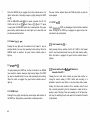
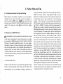
6.6 Changing Tape Head Assembly Z 401 or Z 411 (See Fig. 6)
The procedure is as follows:
1. Switch the SG 631 LOGIC to STOP so that the tape may be lifted out
of the threading slot.
2. Withdraw the front cover cap.
3. Loosen the knurled nuts (A) by rotating to the left, and remove.
4. Pull tape head mount (B) straight up and off.
5. Push the replacing tape head mount down into place; then secure
it with the knurled nuts, rotating them to the right.
6. Replace front cover cap.
6.4 Recording with UHER Telephone Adapter A 261
6.7 Azimuth Adjustment of Playback Head
UHER's galvanic Telephone Adapter A 261 should be connected to the
RADIO socket of the SG 631 LOGIC. Connecting the adapter to your
telephone is a matter for the postal authorities (or telephone company).
During record, the mode selector may be set at either MONO 1 or
MONO 2. It is advisable to make a "test" telephone call in order to
make a record level test, marking or remembering the setting of the
level control. The procedure for making the recording itself is described
in sec. 4.
In hole (C) of the tape head mount there is an adjusting screw with which
the playback head may be tilted, within limits, to the left or right of its
normal perpendicular position so that the SG 631 LOGIC may also play
tapes recorded on machines with non-standard record head positions.
The adjustment should be made with a non-magnetizable screwdriver,
until achieving the best reproduction of high frequencies. Before
adjusting the azimuth, however, make certain that the playback head
surface is free of deposits of tape coating or dust. As poor correspon-
48
dence between record and playback head gaps results in a loss of high
frequencies during playback - and the loss is even greater the wider the
audio track is and the slower the tape speed - correction of the azimuth
of the playback head will usually be required only for half-track recordings and at tape speeds of 3% or 71/2 ips. If the adjustment does not
lead to improved high frequency reproduction, then the record head of
the other recorder may have been heavily clogged or worn. If sound
system loudspeakers are used to monitor the adjusting process, the
treble control on the power amplifier of the system should be opened
up in full.
tape recorder) must be closed.
If a timer is to regulate a recording, a record level test should be made
before the power supply of the input source is switched on via the timer.
Once the timer has switched on the power supply of the input source
and that of the SG 631 LOGIC, the start switch of the timer will switch
the recorder to the functions RECORD and START, and the recording
will commence.
If, for special cases, you would like to have "playback - Start" switching,
kindly consult your nearest UHER service agent who will then make the
necessary changes in your adapter.
For record/playback of recordings made with the SG 631 LOGIC, the
factory-set length of the playback head gap should be restored.
6.8 Putting On the Transparent Dust Cover Z 630
At its two upper corners UHER Transparent Dust Cover Z 630 has supporting plates with ridges that must be pressed into the top ventilating
slits of the SG 631 LOGIC when the machine is in upright position.
To bring the supporting plates into position over the ventilating slits, they
should be lightly pressed outwards. Once fully pressed down into the
slits, the plates will lock firmly in the groove between the upper and
lower sections of the housing. On opening or closing the lid, it will remain
in any intermediate position in which it is placed.
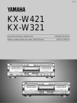
6.9 Operation of the SG 631 LOGIC with UHER Timer A 403
The timer will switch on the power supply for the SG 631 LOGIC as
described in the operating instructions for the timer. For recording,
thread the tape as described in sec. 1.6 above and press the POWER
switch © into its lock-down position. The switch of the UHER-Adapter
K 642 (which must be connected to the ACCESSORY socket of the
Startschalter
Fig. 5
6.10 Tapes and Reels
The quality of the tape used is just as essential to high quality in recording as the quality of the recording equipment. More and more brands
of tapes are being found among the wide assortment on the market
that have greatly differing mechanical and electro-acoustical properties.
That is why UHER has now added to its supply programme blank tape
with characteristics that match, and in some points surpass, the properties of German DIN test tap'e C 264 Z: UHER "professional" tape Z 830.
The base material is stretched polyester plastic with a black anti-static
coating that was especially developed for fast-winding machines. The
49
iron oxide magnetic layer is characterized by its low noise and high output. UHER blank tape Z 830 is supplied on a precision-tooled metal reel
with NAB adapter, reel size 27 cm (IOV2"), length of tape 1,275 m. It has
red and green leaders (12.5 m) and two 26-cm stretches of transparent
foil for photo-sensitive electronic end-of-tape switch-off as well as two
20-cm stretches of metallic foil for electronic end-of-tape shut-off.
Particular attention should be given to the type of reels used. You should
always use two identical reels of the same size (and material) to prevent
the danger of spilling on braking tape transport.
free operation depends upon the exact co-functioning of its mechanics
and electrical components. In designing these important parts, attentio
was given to obtaining the highest degree of operational reliability an
long serviceability. Should malfunctions appear at any time, we re
commend consulting an experienced technician, for experience ha;
shown that he will best spot and correct the difficulty (that will usualH
be of a minor nature). We warn strongly against any tampering by non
technicians as it generally results only in still greater damage.
7. Care and Maintenance
7.1 Cleaning Tape-Touching Parts (See Fig. 6)
Since all important bearing points are equipped with self-lubricating
sintered metal bearing bushes, the SG 631 LOGIC does not require oiling
during its entire service life. Care and maintenance in the main are restricted to checking and cleaning at regular intervals. Our service agents
should be consulted for this task.
The cleaning of the tape-touching parts (that may be needed from time to
time - you may recognize the necessity on noticing a deterioration in
playback quality, particularly of the high tones) can easily be performed
by the user himself. For this purpose, first pull the cover cap in front
of the head mount up and off. The magnetic heads (D), (E), (F) and (G);
the tape guides (H), (I), (J) and (K), the reversing pins (L), (M), (O), (P)
and (Q) will then be easily accessible and clogging deposits of dust
and tape coating may be removed by means of UHER Special Cleaning
Kit Z 172. Caution: The plastic coating of the capstan should be cleaned
only with a cloth dampenened in alcohol.
The SG 631 LOGIC is a highly developed precision machine; its trouble-
50
Fig. 6
7.2 Cleaning the Housing
The housing of the SG 631 LOGIC should always be cleaned with a
soft, moistened cloth so as to avoid build-up of static charges. It is a
well-known fact that a statically charged object strongly attracts dust.
If the housing is particularly dirty, a mild dishwashing detergent may
be added to the water.
Caution!
Before cleaning the housing with a moist cloth, do not fail to disconnect
the SG 631 LOGIC from the mains outlet.
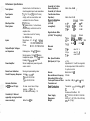
Performance Specifications
Track System:
Tape Speeds:
Counter:
Max. Spool Size:
Drive System:
Inputs:
Outputs/Output Voltages
and Impedance
Power Amplifier:
Quarter-track or half-track due to
interchangeable tape head assemblies
7'/2, 3%, 1% ips, (19, 9.5, 4.75 cm/s)
4-digit, with zero reset button and
automatic foil shut-off device
1O'/2" (27 cm)
2 D.C. hub motors; 1 collectorless,
electronically controlled motor for
capstan drive
1 servo-drive motor for forming
the OMEGA loop.
Microphone 0 . 1 - 80 mV 2 kohms
Radio
1.0-200 mV 20 kohms
Phono
80mV-8V680kohms
Radio approx. 750 mV 15 kohms
Monitor approx. 750 mV 15 kohms
Headphones approx. 1.7 V 120 kohms
Dubbing 700 mV 15 kohms
Stereo headphones power stage with
volume control
Record Level Indication:
Moving-coil peak-reading meter
Overall Frequency Response: V/a ips 20-10,000 Hz
33/4 ips 20-16,000 Hz
7'/2 ips 20-25,000 Hz
Harmonic Distortion
(at 333 Hz and 7/2 ips):
For max. record level of tape
(approx. + 1.5 dB): 3%
For 0 dB meter reading: 1%
Crosstalk (at 1 kHz and
oppositely running dual-track
Better than 60 dB
mono recording):
Crosstalk (at 1 kHz in
Stereo Operation):
Crosstalk (at 1 kHz and
Two-Direction Stereo
Operation):
Signal-to-Noise Ratio
(ref 0 dB,
unweighted):
Better than 45 dB
Better than 60 dB
'/4-track
7V2 ips
3% ips
17/a ips
Signal-to-Noise Ratio
(ref 0 dB, "A" weighting):
Max. Speed Deviation
(Mid-Spool) at 7/2 ips
Erasure:
Bias and Erasure Frequency:
Attenuating Effect on One
Track upon Erasure of Other:
Transistors and
Semi-Conductors:
Power Supply:
Dimensions:
Weight:
56 dB
55 dB
53 dB
1
7V2 ips
33A ips
17/sips
Wow and
Flutter:
f-
17a ips
3% ips
7'/2 ips
/4-track
65 dB \
64 dB [ DIN
63 dB '
'/2-track
58 dB
57 dB
54 dB
V2-track
68 dB |
DIN
67 dB
67 dB '
max. 0.2 %
max. 0.1 °/o
max. 0.05%
±1.5%
Adjustable to 0 % with fine regulator;
stroboscope discs 50 Hz and 60 Hz
for optical control
Better than 72 dB
100 kHz
Less than 1 dB (at 15 kHz, 19 cm/s)
Transistors: 111 (including 13 FET)
IC:
19
Diodes and Rectifiers: 143
A.C. 110/130 V, 220/240 V 50/60 Hz
2OV2" x 6" x 16" (510 x 146 x 400 mm)
281/2 lbs. (13 kg)
51
UHER WERKE MUNCHEN 366-48210/DEF/lll/035/1179-R
Printed in Germany