1
DENTAL X-RAY
097
SERVICE
MANUAL
( for 220V, 230V, 240V )
R
INDEX
SECTION 1 : TECHNICAL DATA
page
[1] ELECTRICAL AND RADIATION DATA ・・・・・・・・・・・・・・・・・・・・・・・・・・・・・・・・・・・・・・2
[2] PHYSICAL DIMENSIONS ・・・・・・・・・・・・・・・・・・・・・・・・・・・・・・・・・・・・・・・・・・・・・・・・・・3
[3] TUBE HEAD THERMAL CHARACTERISTICS ・・・・・・・・・・・・・・・・・・・・・・・・・・・・・・・・5
SECTION 2 : OPERATION INSTRUCTION
[1] LAYOUT OF CONTROL BOX ・・・・・・・・・・・・・・・・・・・・・・・・・・・・・・・・・・・・・・・・・・・・・・6
[2] FUNCTION OF CONTROLS ・・・・・・・・・・・・・・・・・・・・・・・・・・・・・・・・・・・・・・・・・・・・・・・・7
[3] OPERATING PROCEDURES ・・・・・・・・・・・・・・・・・・・・・・・・・・・・・・・・・・・・・・・・・・・9
[4] OPTIONAL HAND EXPOSURE SWITCH・・・・・・・・・・・・・・・・・・・・・・・・・・・・・・・・・・・・・・9
[5] ALTERATION OF SETTING ・・・・・・・・・・・・・・・・・・・・・・・・・・・・・・・・・・・・・・・・・・・・・・10
SECTION 3 : DESCRIPTION FOR FUNCTIONS
[1] GENERAL ・・・・・・・・・・・・・・・・・・・・・・・・・・・・・・・・・・・・・・・・・・・・・・・・・・・・・・・・・・・・・・15
[2] AUTOMATIC VOLTAGE REGULATOR ・・・・・・・・・・・・・・・・・・・・・・・・・・・・・・・・・・・・・16
[3] PRIMARY CIRCUIT OF HIGH VOLTAGE TRANSFORMER ・・・・・・・・・・・・・・・・・・・・16
[4] PRIMARY CIRCUIT OF FILAMENT TRANSFORMER ・・・・・・・・・・・・・・・・・・・・・・・・・17
[5] AUTOMATIC TUBE CURRENT CONTROL ・・・・・・・・・・・・・・・・・・・・・・・・・・・・・・・・・・17
SECTION 4 : ADJUSTMENT
[1] AVR VOLTAGE ・・・・・・・・・・・・・・・・・・・・・・・・・・・・・・・・・・・・・・・・・・・・・・・・・・・・・・・・・18
[2] INSPECTION OF TUBE CURRENT ・・・・・・・・・・・・・・・・・・・・・・・・・・・・・・・・・・・・・・・・・20
[3] ADJUSTMENT OF TUBE CURRENT ・・・・・・・・・・・・・・・・・・・・・・・・・・・・・・・・・・・・・・・・21
[4] ADJUSTMENT OF LINE VOLTAGE MEASUREMENT ERROR ・・・・・・・・・・・・・・・・・22
SECTION 5 : PERIODIC INSPECTION AND ADJUSTMENT
[1] ELECTRICAL INSPECTION AND ADJUSTMENT ・・・・・・・・・・・・・・・・・・・・・・・・・・・・23
[2] MECHANICAL INSPECTION ・・・・・・・・・・・・・・・・・・・・・・・・・・・・・・・・・・・・・・・・・・・・・・24
SECTION 6 : ERROR CODE ・・・・・・・・・・・・・・・・・・・・・・・・・・・・・・・・・・・・・・・・・・・・・・・・・・・25
SECTION 7 : TROUBLE SHOOTING ・・・・・・・・・・・・・・・・・・・・・・・・・・・・・・・・・・・・・・・・・・・・27
SECTION 8 : REPLACEMENT OF COMPONENT
[1] CONTROL BOX ・・・・・・・・・・・・・・・・・・・・・・・・・・・・・・・・・・・・・・・・・・・・・・・・・・・・・・・・29
[2] TUBE HEAD ・・・・・・・・・・・・・・・・・・・・・・・・・・・・・・・・・・・・・・・・・・・・・・・・・・・・・・・・・・・29
SECTION 9 : CIRCUIT DIAGRAM ・・・・・・・・・・・・・・・・・・・・・・・・・・・・・・・・・・・・・・・・・・・・・30
-1-
SECTION 1 : TECHNICAL DATA
[ 1 ] ELECTRICAL AND RADIATION DATA
1. Nominal focal spot value --------------------------------- 0.7 (IEC60336)
2. Rated peak tube potential -------------------------------- 70 kV
3. Rated tube current ----------------------------------------- 4 mA / 7 mA selectable
4. Maximum rated peak tube potential -------------------- 70 kV
5.
Rated Line Voltage
Minimum Line Voltage
Maximum Line Voltage
Rated Line Power (Momentary rating)
Rated Line Current at 7mA
Maximum Line Current at 7mA
(Internal Resistance Range of Line Voltage Regulation
220
230
240
[Vac]
[Vac]
198
207
216
[Vac]
242
253
264
[kVA]
0.8
0.8
0.8
[Aac]
3.4
3.4
3.4
[Aac]
3.7
3.7
3.7
[Ω] ) (1.27max)
(1.33max)
(1.38max)
[%]
0~2 0~2
0~2
6. Power line frequency ------------------------------------- 50 / 60Hz, Single Phase
7. Line power (Long term rating) -------------------------- 12VA
8. Exposure time ---------------------------------------------- 0.02 ~ 3.2 sec.(ON and OFF are zero croseed)
9. Timer accuracy ............................................................ ±1 pulse (= 1/50 sec. or 1/60 sec.)
10. Inherent filtration------------------------------------------ 1.7 mm Al Equivalent
11. Added filtration ------------------------------------------- 0.5 mm Al
12. Minimum filtration permanently in useful beam ----- 2.2 mm Al Equivalent at 70 kV(peak)
13. Nominal roentgen output
4 mA 7 mA
a. Distal end of regular cone ----------------------------- 4.2mGy/sec.
7.1mGy/sec. ±40%
b. Distal end of long cone -------------------------------- 2.4mGy/sec.
3.3mGy/sec. ±40%
14. Cone
Source to skin distance
Field size
a. Regular cone............................................................. 204 mm
58mm dia., circular
b. Long cone (Option) ................................................. 305 mm
58mm dia., circular
15. Leakage technique factor ............................................ 70 kV(peak), 494 mAs at 1 hour
16. Duty cycle ................................................................... 1 : 50 (0.5 sec. exposure with 25 sec. interval)
17. Source to the base of cone distance ............................ 81 mm
18. Reference current time product ................................... 22.4 mAs (70 kV(peak), 7 mA, 3.2 sec.)
19. Maximum earth leakage current ................................. 0.5 mA
20. Tolerance of the focal spot marking ............................ ±1 mm
21. Target angle and material ............................................16 ± 1°, Tungsten
22. Maximum anode heat content ..................................... 4.3 kJ (6 kHU)
23. Maximum x-ray tube assembly heat content .............. 150 kJ (210 kHU)
24. Nominal electrical output of H.V.Generator .............. 0.36 kW at 70 kV, 7 mA
25. Measurement base of technique factors
Focal spot marking
Reference axis
a. Peak tube potential ................................................... Peak tube potential of conducting half cycle
b. Tube current ............................................................. Average of tube current during one cycle of
line frequency
c. Exposure time........................................................... Impulses of power line frequency
26 Environmental condition for storage............................-20 ~ 70℃, 10 ~ 90%, 500 ~ 1060 hPa
27. Environmental condition for operation........................10 ~ 40℃, 30 ~ 75%, 700 ~ 1060 hPa
28. Rotation angle of head ................................................ Horizontal 0 ~ 600°, Vertical 0 ~ 300°
29. Service Life..................................................................10 Years
-2-
220°
18-7/16"
(468)
WK Type
4-5/8"
(117)
[ 2 ] PHYSICAL DIMENSIONS
( ) =mm
5-5/8"(142)
31-1/2" (800)
Max. 46-7/8" (1190)
Stroke 43-5/16" (1100)
600°
3-3/16"
(80)
90
°
2-1/4"
(58)
56-1/2" ~ 78-3/16"
(1435 ~ 1985)
°
90
19-1/16" ~ 62-3/16"
(480 ~ 1580)
45-1/2"
(1156)
Location for Wires
34-1/2"
(876)
300°
MAX 73-1/8" (1857)
6-3/16" (157)
38-5/16" (973)
39-3/16" (995)
48-5/16" (1243)
Short Cone
Long Cone
15-11/16" (398)
19-11/16" (499)
50-5/16" (1294)
48-1/4" (1225)
39-1/2" (1003)
13/16" (20)
4-1/2" (115)
1-7/8"
(47)
9-3/16"
(233)
28-1/2" (723)
Cabinet Frame
7-15/16"
(226)
10-1/4"
(260)
208 mm
Focal Spot Marking
Reference Axis
SSD (Source to Skin Distance) :
a. Regular cone----------8 inches (203 mm)
b. Long cone------------12 inches (305mm)
SSD
SSD + 195 mm
Fig.1
Dimensions
-3-
FM Type
FK1/FK2 Type
680
22
220
°
536
117
80°
117
825
0°
600°
600°
Max.1190
Stroke 1100
300
80
80
95
Max.695
Max.695
Max.1190
Stroke 1100
Sub Controller
Sub Controller
0°
30
°
0
30
Max.1300
Max.1612
Stroke 1100
1335
1335
270
Main Controller
125
Main Controller
270
Max.1718
Stroke 1100
Max.1000
RK Type
CK Type
0°
117
22
500
180
°
0°
30
500
117
26
0°
600°
300
Max.1190
Stroke1100
600°
260
350
80
187
1495
Fig.1-6 Dimensions
-4-
0°
1350
300°
Max.1713
Stroke1100
270
1630(1970)
2300
506
Main Controller
775
Stroke 700
106
450
Stroke 200
Max.2140
75
470
670
400
Max.695
130
80
30
270
[ 3 ] TUBE HEAD THERMAL CHARACTERISTICS
A. Interval between each exposure
The temperature inside of the tube head rises when an exposure is made. The value of the heat
generated is measured in Heat Units (HU), which is the product of tube potential, tube current
and exposure time. Excessive heat will accumulate inside of the tube head if the x-ray is used
without a proper cool down interval between each exposure. The excessive heat may damage
the x-ray tube, high voltage generator or both.
B. Duty cycle
A cool down interval of 50 seconds or more must be allowed between each 1 second exposure.
(a 25 second cool down must be allowed between each 0.5 second exposure.) This will avoid
the accumulation of excess heat and prolong the tube head life.
C. Tube head cooling curve
2. Anode thermal characteristics
1. Tube housing cooling curve
250
4500
4300J
100W
4000
200
3500
Heat Storage (kH.U.)
3000
Heat Storage [J]
150
100
50W
2500
2000
1500
COOLING
1000
50
500
0
0
0
20
40
60
80
100
120
140
0
Time in Minutes
20
50kV
Tube Current [mA]
18
60kV
14
70kV
12
10
8
6
0.1
0.2
0.3
0.5 0.7
1
100
150
Time [S]
3. Maximum rating chart
16
50
2
3
5
7
10
Exposure Time [S]
-5-
200
250
300
SECTION 2 : OPERATION INSTRUCTIONS
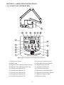
[ 1 ] LAYOUT OF CONTROLLERS
1
10
11
12
16
13
14
3
15
4
9
5
6
8
7
17
2
18
Fig.2 Major Components and Control Identification
(1)MainPowerSwitch
(2)ReadyLight
(3) Exposure Time Adjusting Switch (Down)
(4) Exposure Time Adjusting Switch (Up)
(5)ToothSelectionSwitch(T1)
(6)ToothSelectionSwitch(T2)
(7)ToothSelectionSwitch(T3)
(8)ToothSelectionSwitch(T4)
(9)ToothSelectionSwitch(T5)
-6-
(10)ConeTypeSelectionSwitch
(11)FilmSpeedSelectionSwitch
(12) Digital Imaging Switch
(13) 4mA Selection Switch
(14)7mASelectionSwitch
(15)PatientSizeSelectionSwitch
(16)ExposureTimeDisplayWindow
(17)ExposureWarningLight
(18)ExposureSwitch
[ 2 ] FUNCTION OF CONTROLS
(1) Main Power Switch
PushingtheuppersideofthisswitchtotheONpositionenergizesthex-rayunit.(Readylight
and pre-select light for cone type, film or digital, mA, and patient size illuminate.)
ItisrecommendedtokeepthisswitchOFFwhentheunitisnotinuse,inordertopreventan
accidentalexposure.
IMPORTANT : To prevent the risk of an accidental exposure, push the lower side
of this switch to the OFF position, when the unit is not in use.
(2) Ready Light
Thislightilluminateswhenthelinevoltageiswithinoperablerange. When this light is not on, exposurecannotbemade.
(3)(4) Exposure Time Adjusting Switches
Bymomentarilypushingthe(or)switch,theexposuretimedisplayedincreases(or
decreses) byoneincrement. Bykeepingtheswitchdepressedmore2sec.,theexposuretime
displayed increases(ordecreases)continuouslyuntiltheswitchisreleased.
Model097hasthefollowing23exposuretimesettings:
0.00,0.02,0.03,0.04,0.05,0.06,0.08,0.10,0.13,0.16,0.20,0.25,0.32,0.40
0.50,0.63,0.80,1.00,1.25,1.60,2.00,2.50,3.20(sec.)
(5) ~ (9) Tooth Selection Switches (T1 ~ T5)
Pushingoneoftheseswitchessetstheexposuretimeautomaticallyforthefollowing(10)~(15).
(5)T1:IncisorofMandible
(6)T2:IncisorofMaxilla,Cuspid&PremolarofMandible
(7)T3:Cuspid&PremolarofMaxilla,MolarsofMandible,BiteWing
(8)T4:MolarofMaxilla,BiteWingMolars
(9)T5:Occlusal
IftheT1switch(5)isdepressedmorethan3sec.,unitgoesinto“LockMode”.
Inlockmode,theonlyfunctionalswitchisthepowerswitch.Toexitfromthelockmode,
depresstheT1switchmorethan3sec.again.
(10) Cone Type Selection Switch
Depressingthisswitchformorethan2sec.selectstheconetype:8”standardconeor12”
optionallongcone.(Iftheoptionalrectangularconeistobeused,selectthe8”conesetting.)
(11) Film Speed Selection Switch
a. BELRAY II has 16 film speed settings : (F.00 ~ F.15)
Twospeedsettingsarepre-setatthefactory(a&b)andcanbeselectedwith(11).
a = Film speed No. F.09 (equivalent to ISO speed group “ D” or Kodak Ultra-Speed film)
b = Film speed No. F.04 (equivalent to ISO speed group “ F/E” or Kodak InSight film)
b. Pushing this switch momentarily displays the selected film speed setting in the Exposure
Time Display Window(16).
Depressing this switch for more than 2 sec. changes the film type being selected.
c.IftheDigital Imaging Switch (12) is depressed, both of the film speed indicating light
(a & b) areturnedoff.
(12) Digital Imaging Switch
Ifadigitalimagingsystemisused,shorterexposuretimeisoftenrequired.BELRAYIIhas
16 speedsfordigitalimaging:(d.00~d.15).Pushingthisswitchmomentarilydisplaysthe
speed beingselectedintheExposure Time Display Window(16).Withthefactoryspeed
setting d.06, theexposuretimebecomeshalfofF.06setting.
-7-
TABLE 1. Speed Setting and Exposure Time (Regular Cone)
Speed
Setting
F.09
F.04
d.06
mA
4
7
4
7
4
7
Adult
F.09
F.04
d.06
mA
4
7
4
7
4
7
Obese
T1
T2
T3
T4
T5
T1
T2
T3
T4
T5
T1
T2
T3
T4
T5
0.20
0.32
0.40
0.50
0.80
0.32
0.50
0.63
0.80
1.25
0.40
0.63
0.80
1.00
1.60
0.10
0.20
0.20
0.32
0.40
0.20
0.32
0.40
0.50
0.63
0.20
0.40
0.40
0.63
0.80
0.08
0.13
0.16
0.20
0.32
0.13
0.20
0.25
0.32
0.50
0.16
0.25
0.32
0.40
0.63
0.05
0.08
0.10
0.13
0.16
0.08
0.13
0.16
0.20
0.32
0.10
0.16
0.20
0.25
0.32
0.06
0.10
0.10
0.16
0.20
0.10
0.16
0.20
0.25
0.40
0.10
0.20
0.25
0.32
0.40
0.03
0.05
0.06
0.08
0.13
0.05
0.08
0.10
0.13
0.20
0.06
0.10
0.13
0.16
0.25
TABLE 2. Speed Setting and Exposure Time (Long Cone)
Speed
Setting
[unit : sec.]
Child
[unit : sec.]
Child
Adult
Obese
T1
T2
T3
T4
T5
T1
T2
T3
T4
T5
T1
T2
T3
T4
T5
0.40
0.63
0.80
1.00
1.60
0.63
1.25
1.25
2.00
2.50
0.80
1.25
1.60
2.00
3.20
0.25
0.40
0.50
0.63
1.00
0.40
0.63
1.80
1.00
1.60
0.50
0.80
1.00
1.25
2.00
0.16
0.25
0.32
0.50
0.63
0.25
0.50
0.50
0.80
1.00
0.32
0.50
0.63
1.00
1.25
0.10
0.16
0.20
0.25
0.40
0.16
0.25
0.32
0.40
0.63
0.20
0.32
0.40
0.50
0.80
0.13
0.20
0.25
0.32
0.50
0.20
0.32
0.40
0.50
0.80
0.25
0.40
0.50
0.63
1.00
0.06
0.13
0.13
0.20
0.25
0.10
0.20
0.25
0.32
0.40
0.13
0.25
0.25
0.40
0.50
(13) 4mA Selection Switch
By momentarily depressing this switch, the tube current is set at 4mA.
When Film switch is depressed, the tube current setting will be automatically changed to 7mA.
(14) 7mA Selection Switch
By momentarily depressing this switch, the tube current is set at 7mA.
When Digital switch is depressed, the tube current setting will be automatically changed to 4mA.
(15) Patient Size Selection Switch
This switch alters the selection of patient type/size to be radiographed (child
and sets the exposure time automatically.
NOTE : Setting or adjusting the exposure time manually (with
(5) ~ (15) functions.
or
adult
Obese
child)
switch) supersedes
(16) Exposure Time Display Window
This window displays the selected exposure time. If an abnormal condition exists or a malfunction
occurs, an Error Code is displayed. (See Section 6 : ERROR CODE)
(17) Exposure Warning Light
Illumination of this light indicates the unit is producing x-radiation.
(18) Exposure Switch
This switch initiates radiographic exposure. When making an exposure, depress and hold this
switch unit the Exposure Warning Light (17) and the audible warning shut off. Failure to keep this
switch depressed will result in the premature termination of the exposure and error code E.00 will
be displayed in Exposure Time Display Window (16).
-8-
[ 3 ] OPERATING PROCEDURES
1.TurnONtheMainPowerSwitch(1).
2. Confirm that Ready Light (2) is illuminated.
NOTE : The ready light will not illuminate unless the incoming line voltage is correct and
within the x-ray’s operable range.
3. Select the appropriate tooth type (5) ~ (9), and confirm the pre-selected conditions (cone type, film
ordigital,mAandpatientsize)aresuitableforexposure.
NOTE : To manually set the exposure time, depress either of the manual Exposure Time
Adjust Switches (
or ) until the desired exposure time appears in the Exposure
Time Display Window (16). While the unit is in manual mode, other selection switches
(5) ~ (15) do not affect exposure time. (All of the tooth selection lights are off.)
To return to the automatic exposure time selection mode, depress any one of Tooth
Selection Switches (5) ~ (9).
4.DepresstheExposureSwitch(8).WhentheExposureSwitchisdepressed,theExposureWarning
Light(17)illuminatesandtheaudiblewarningsounds.DonotreleasetheExposureSwitchuntilthe
ExposureWarningLightandaudiblewarningautomaticallyshutoff.Failuretokeeptheswitch
depressedwillresultinexposurebeingterminatedprematurely.
5. To continue to radiograph other teeth, just select appropriate Tooth Selection Switches (5) ~ (9).
IMPORTANT : To protect x-ray tubehead from heat accumulation, wait for a time interval
that is equal to 50 times the selected exposure time before making additional
exposures. (Example : a 25 sec. wait is necessary between exposures that are
0.5 sec. in duration.)
6.TurnOFFtheMainPowerSwitch(1)inordertopreventaccidentalexposurewhentheunitisnotinuse.
NOTE : If the unit is left over 8 min. without being operated and Main Power Switch (1) is kept
on, figure “ 1” runs through the Exposure Time Display Window (16).
This does not mean that malfunction of the unit has occurred ; this is an energy saving
feature. The unit returns to ready condition by pressing any one of the switches, except
the Exposure Switch (18).
[ 4 ] OPTIONAL HAND EXPOSURE SWITCH
Anoptionalhandexposureswitchcanbeconnectedtothesubcontroller.Sincethisexposureswitch
hasacoiledcord,operatorscanstandinthemostsuitablepositionforoperation.
Ascontrollerhasseparateconnectorforthisexposureswitch,bothexposureswitch(18)onthefront
panelofsubcontrollerandthishandexposureswitchcanbeused.
Iflocalcodeprohibitsuseofboth,disconnecttheconnectorofeitherswitch.
-9-
[ 5 ] ALTERATION OF SETTINGS
( 1 ) SPEED SETTING FOR FILM AND DIGITAL IMAGING
A. FILM SPEED
Prior to shipment of the x-ray from the factory, the following two film speeds are programmed
to beselectedbytheFilmSpeedSelectionSwitch.
a = Film speed F.09 (equivalent to ISO speed group "D", or Kodak Ultra-speed Film)
b = Film speed F.04 (equivalent to ISO speed group "F/E", or Kodak InSight Film)
In addition to these two speeds, BELRAY II 097 x-ray can provide 16 different film speeds
(F.00~F.15)andanytwoofthemcanbeprogrammedforeasyselection.Ifthedoctor uses
a different film speed, or prefers darker (or lighter) radiographs, the new speed can be
programmed as follows. Higher speed settings make films darker. If film speed is increased
by1,exposuretimebecomes25%longer.
1.Keepthe4mAselectionswitchand7mAselectionswitchdepressedsimultaneouslyfor
more than 3 seconds. Release the switches if the ready light starts to flash.
2. Push F switch momentarily until the "a" light above the F switch illuminates. The exposure
time display window shows the present film speed for "a" setting. (The factory default setting,
F.09 should be displayed.) By depressing
or
switch, increase or decrease film speed
number until desired number for "a" setting is displayed.
3. To change the "b" setting from the factory default, F.05, push F switch momentarily until the
"b" light illuminates. By depressing
or
switch, increase or decrease film speed until the
desired number for "b" setting is displayed.
4.PressT1 switchtostorethesesettings,thenturnthemainpowerswitchoff.
B. SPEED FOR DIGITAL IMAGING
BELRAYII 097x-rayhas16speedsfordigitalimaging(d.00~d.15).Thefactory setting
isd.06andwiththissettingtheexposuretimebecomeshalfofF.06setting.
Asthesensitivityisdifferentaccordingtoeachmanufacturerofdigitalimagingsensors,this
setting should be adjusted. To get a darker image, increase the speed setting and to get a lighter
image,decreasethespeedsetting.Ifthespeedsettingisincreasedby1,exposuretimebecomes
12%longer.
1.Keep4mAselectionswitchand7mAselectionswitchdepressedsimultaneouslyformorethan
3 seconds. Release the switches if the ready light starts to flash.
2.PushDswitchmomentarilyuntilthelightabovetheDswitchilluminatesandtheexposure
timedisplaywindowshowsthepresentspeedsetting.(Thefactorydefaultsettingd.06should
bedisplayed.)
3.Bydepressingorswitch,increaseordecreasespeeduntilthedesirednumberis
displayed.
4.PressT1 switchtostorethesesettings,thenturnthemainpowerswitchoff.
-10-
Table 3. Film number and exposure time in film mode (at 7mA with regular cone)
patient
teeth
F.00
F.01
F.02
F.03
F.04
F.05
F.06
F.07
F.08
F.09
F.10
F.11
F.12
F.13
F.14
F.15
T1
0.02
0.03
0.03
0.04
0.05
0.05
0.06
0.08
0.10
0.10
0.13
0.16
0.20
0.25
0.25
0.32
T2
0.04
0.04
0.05
0.06
0.08
0.08
0.10
0.13
0.16
0.20
0.20
0.25
0.32
0.40
0.50
0.50
Child
T3
0.04
0.05
0.06
0.08
0.10
0.10
0.13
0.16
0.20
0.20
0.25
0.32
0.40
0.50
0.50
0.63
T4
0.06
0.08
0.08
0.10
0.13
0.13
0.16
0.20
0.25
0.32
0.32
0.40
0.50
0.63
0.80
0.80
T5
0.08
0.10
0.13
0.16
0.16
0.20
0.25
0.32
0.40
0.40
0.50
0.63
0.80
0.80
1.00
1.25
T1
0.04
0.04
0.05
0.06
0.08
0.08
0.10
0.13
0.16
0.20
0.20
0.25
0.32
0.40
0.40
0.50
T2
0.06
0.08
0.08
0.10
0.13
0.16
0.16
0.20
0.25
0.32
0.40
0.40
0.50
0.63
0.80
0.80
Adult
T3
0.08
0.08
0.10
0.13
0.16
0.16
0.20
0.25
0.32
0.40
0.40
0.50
0.63
0.80
0.80
1.00
T4
0.10
0.10
0.13
0.16
0.20
0.25
0.25
0.32
0.40
0.50
0.63
0.63
0.80
1.00
1.25
1.60
T5
0.13
0.16
0.20
0.25
0.32
0.32
0.40
0.50
0.63
0.63
0.80
1.00
1.25
1.60
1.60
2.00
T1
0.04
0.05
0.06
0.08
0.10
0.10
0.13
0.16
0.20
0.20
0.25
0.32
0.40
0.50
0.50
0.63
T2
0.08
0.08
0.10
0.13
0.16
0.16
0.20
0.25
0.32
0.40
0.40
0.50
0.63
0.80
1.00
1.00
Obese
T3
0.08
0.10
0.13
0.16
0.20
0.20
0.25
0.32
0.40
0.40
0.50
0.63
0.80
1.00
1.00
1.25
Table 4. Film number and exposure time in film mode (at 4mA with regular cone)
(Unit : Sec.)
T4
0.13
0.13
0.16
0.20
0.25
0.32
0.32
0.40
0.50
0.63
0.63
0.80
1.00
1.25
1.60
1.60
T5
0.16
0.20
0.25
0.32
0.32
0.40
0.50
0.63
0.80
0.80
1.00
1.25
1.60
1.60
2.00
2.50
(Unit : Sec.)
patient
Child
Adult
Obese
teeth
T1
T2
T3
T4
T5
T1
T2
T3
T4
T5
T1
T2
T3
T4
T5
F.00
0.04 0.06 0.08 0.10 0.16 0.06 0.10 0.13 0.16 0.25 0.08 0.13 0.16 0.20 0.32
F.01
0.05 0.08 0.10 0.13 0.20 0.08 0.13 0.16 0.20 0.32 0.10 0.16 0.20 0.25 0.40
F.02
0.06 0.10 0.10 0.16 0.20 0.10 0.16 0.20 0.25 0.32 0.10 0.20 0.20 0.32 0.40
F.03
0.06 0.10 0.13 0.16 0.25 0.10 0.16 0.20 0.32 0.40 0.13 0.20 0.25 0.32 0.50
F.04
0.08 0.13 0.16 0.20 0.32 0.13 0.20 0.25 0.32 0.50 0.16 0.25 0.32 0.40 0.63
F.05
0.10 0.16 0.20 0.25 0.40 0.16 0.25 0.32 0.40 0.63 0.20 0.32 0.40 0.50 0.80
F.06
0.10 0.20 0.25 0.32 0.40 0.20 0.32 0.40 0.50 0.80 0.25 0.40 0.50 0.63 0.80
F.07
0.13 0.25 0.25 0.40 0.50 0.20 0.40 0.40 0.63 0.80 0.25 0.50 0.50 0.80 1.00
F.08
0.16 0.25 0.32 0.40 0.63 0.25 0.40 0.50 0.63 1.00 0.32 0.50 0.63 0.80 1.25
F.09
0.20 0.32 0.40 0.50 0.80 0.32 0.50 0.63 0.80 1.25 0.40 0.63 0.80 1.00 1.60
F.10
0.25 0.40 0.50 0.63 1.00 0.40 0.63 0.80 1.00 1.60 0.50 0.80 1.00 1.25 2.00
F.11
0.25 0.50 0.63 0.80 1.00 0.50 0.80 1.00 1.25 1.60 0.63 1.00 1.25 1.60 2.00
F.12
0.32 0.50 0.63 1.00 1.25 0.50 1.00 1.00 1.60 2.00 0.63 1.25 1.25 2.00 2.50
F.13
0.40 0.63 0.80 1.00 1.60 0.63 1.00 1.25 1.60 2.50 0.80 1.25 1.60 2.00 3.20
F.14
0.50 0.80 1.00 1.25 2.00 0.80 1.25 1.60 2.00 3.20 1.00 1.60 2.00 2.50
*
F.15
0.63 1.00 1.25 1.60 2.50 1.00 1.60 2.00 2.50
* 1.25 2.00 2.50 3.20
*
("*" in the table denotes that a tube current setting is automatically switched and set at the most appropriate time.)
- 11 -
Table 5. Film number and exposure time in film mode (at 7mA with long cone)
patient
teeth
F.00
F.01
F.02
F.03
F.04
F.05
F.06
F.07
F.08
F.09
F.10
F.11
F.12
F.13
F.14
F.15
T1
0.05
0.06
0.06
0.08
0.10
0.10
0.13
0.16
0.20
0.25
0.32
0.32
0.40
0.50
0.63
0.63
T2
0.08
0.10
0.10
0.13
0.16
0.20
0.25
0.25
0.32
0.40
0.50
0.63
0.63
0.80
1.00
1.25
Child
T3
0.10
0.10
0.13
0.16
0.20
0.25
0.25
0.32
0.40
0.50
0.63
0.63
0.80
1.00
1.25
1.25
T4
0.13
0.16
0.20
0.20
0.25
0.32
0.40
0.40
0.50
0.63
0.80
1.00
1.00
1.25
1.60
2.00
T5
0.20
0.20
0.25
0.32
0.40
0.40
0.50
0.63
0.80
1.00
1.00
1.25
1.60
2.00
2.50
2.50
T1
0.08
0.10
0.10
0.13
0.16
0.20
0.25
0.25
0.32
0.40
0.50
0.50
0.63
0.80
1.00
1.25
T2
0.13
0.16
0.20
0.20
0.25
0.32
0.40
0.50
0.50
0.63
0.80
1.00
1.00
1.25
1.60
2.00
Adult
T3
0.16
0.20
0.20
0.25
0.32
0.40
0.50
0.50
0.63
0.80
1.00
1.00
1.25
1.60
2.00
2.50
T4
0.20
0.25
0.32
0.32
0.40
0.50
0.63
0.80
0.80
1.00
1.25
1.60
1.60
2.00
2.50
3.20
T5
0.32
0.32
0.40
0.50
0.63
0.80
0.80
1.00
1.25
1.60
2.00
2.00
2.50
3.20
3.20
3.20
T1
0.10
0.10
0.13
0.16
0.20
0.25
0.25
0.32
0.40
0.50
0.63
0.63
0.80
1.00
1.25
1.25
T2
0.16
0.20
0.25
0.25
0.32
0.40
0.50
0.50
0.63
0.80
1.00
1.25
1.25
1.60
2.00
2.50
Table 6. Film number and exposure time in film mode (at 4mA with long cone)
(Unit : Sec.)
Obese
T3
0.20
0.20
0.25
0.32
0.40
0.50
0.50
0.63
0.80
1.00
1.25
1.25
1.60
2.00
2.50
2.50
T4
0.25
0.32
0.40
0.40
0.50
0.63
0.80
0.80
1.00
1.25
1.60
2.00
2.00
2.50
3.20
3.20
T5
0.40
0.40
0.50
0.63
0.80
0.80
1.00
1.25
1.60
2.00
2.00
2.50
3.20
3.20
3.20
3.20
(Unit : Sec.)
Child
Adult
Obese
patient
teeth
T1
T2
T3
T4
T5
T1
T2
T3
T4
T5
T1
T2
T3
T4
T5
F.00
0.08 0.13 0.16 0.20 0.32 0.13 0.20 0.25 0.32 0.50 0.16 0.25 0.32 0.40 0.63
F.01
0.10 0.16 0.20 0.25 0.40 0.16 0.25 0.32 0.40 0.63 0.20 0.32 0.40 0.50 0.80
F.02
0.13 0.20 0.25 0.32 0.50 0.20 0.32 0.40 0.50 0.80 0.25 0.40 0.50 0.63 1.00
F.03
0.13 0.25 0.25 0.40 0.50 0.25 0.40 0.50 0.63 0.80 0.25 0.50 0.50 0.80 1.00
F.04
0.16 0.25 0.32 0.50 0.63 0.25 0.50 0.50 0.80 1.00 0.32 0.50 0.63 1.00 1.25
F.05
0.20 0.32 0.40 0.50 0.80 0.32 0.50 0.63 0.80 1.25 0.40 0.63 0.80 1.00 1.60
F.06
0.25 0.40 0.50 0.63 1.00 0.40 0.63 0.80 1.00 1.60 0.50 0.80 1.00 1.25 2.00
F.07
0.32 0.50 0.63 0.80 1.25 0.50 0.80 1.00 1.25 2.00 0.63 1.00 1.25 1.60 2.50
F.08
0.32 0.63 0.63 1.00 1.25 0.63 1.00 1.25 1.60 2.00 0.63 1.25 1.25 2.00 2.50
F.09
0.40 0.63 0.80 1.00 1.60 0.63 1.25 1.25 2.00 2.50 0.80 1.25 1.60 2.00 3.20
F.10
0.50 0.80 1.00 1.25 2.00 0.80 1.25 1.60 2.00 3.20 1.00 1.60 2.00 2.50
*
F.11
0.63 1.00 1.25 1.60 2.50 1.00 1.60 2.00 2.50
* 1.25 2.00 2.50 3.20
*
F.12
0.80 1.25 1.60 2.00 2.50 1.25 2.00 2.50 3.20
* 1.60 2.50 3.20
*
*
F.13
0.80 1.60 1.60 2.50 3.20 1.25 2.50 2.50
*
* 1.60 3.20 3.20
*
*
F.14
1.00 1.60 2.00 2.50
* 1.60 2.50 3.20
*
* 2.00 3.20
*
*
*
F.15
1.25 2.00 2.50 3.20
* 2.00 3.20
*
*
* 2.50
*
*
*
*
("*" in the table denotes that a tube current setting is automatically switched and set at the most appropriate time.)
- 12 -
Table 7. Sensor sensitivity number and exposure time in digital mode (at 7mA with regular cone)
Child
Adult
Obese
patient
teeth
T1
T2
T3
T4
T5
T1
T2
T3
T4
T5
T1
T2
T3
T4
T5
d.00
* 0.02 0.02 0.03 0.04 0.02 0.03 0.04 0.05 0.06 0.02 0.04 0.04 0.06 0.08
d.01
* 0.02 0.03 0.04 0.05 0.02 0.04 0.04 0.06 0.08 0.03 0.04 0.05 0.08 0.10
d.02
* 0.03 0.03 0.04 0.06 0.03 0.04 0.05 0.06 0.10 0.03 0.05 0.06 0.08 0.13
d.03
0.02 0.03 0.04 0.05 0.08 0.03 0.05 0.06 0.08 0.13 0.04 0.06 0.08 0.10 0.16
d.04
0.02 0.04 0.05 0.06 0.08 0.04 0.06 0.08 0.10 0.13 0.05 0.08 0.10 0.13 0.16
d.05
0.03 0.05 0.05 0.08 0.10 0.04 0.08 0.08 0.13 0.16 0.05 0.08 0.10 0.13 0.20
d.06
0.03 0.05 0.06 0.08 0.13 0.05 0.08 0.10 0.13 0.20 0.06 0.10 0.13 0.16 0.25
d.07
0.04 0.06 0.08 0.10 0.16 0.06 0.10 0.13 0.16 0.25 0.08 0.13 0.16 0.20 0.32
d.08
0.05 0.08 0.10 0.13 0.20 0.08 0.13 0.16 0.20 0.32 0.10 0.16 0.20 0.25 0.40
d.09
0.06 0.10 0.10 0.16 0.20 0.10 0.16 0.20 0.25 0.32 0.10 0.20 0.20 0.32 0.40
d.10
0.06 0.10 0.13 0.16 0.25 0.10 0.20 0.20 0.32 0.40 0.13 0.20 0.25 0.32 0.50
d.11
0.08 0.13 0.16 0.20 0.32 0.13 0.20 0.25 0.32 0.50 0.16 0.25 0.32 0.40 0.63
d.12
0.10 0.16 0.20 0.25 0.40 0.16 0.25 0.32 0.40 0.63 0.20 0.32 0.40 0.50 0.80
d.13
0.13 0.20 0.25 0.32 0.40 0.20 0.32 0.40 0.50 0.80 0.25 0.40 0.50 0.63 0.80
d.14
0.13 0.25 0.25 0.40 0.50 0.20 0.40 0.40 0.63 0.80 0.25 0.50 0.50 0.80 1.00
d.15
0.16 0.25 0.32 0.40 0.63 0.25 0.40 0.50 0.80 1.00 0.32 0.50 0.63 0.80 1.25
("*" in the table denotes that a tube current setting is automatically switched and set at the most appropriate time.)
Table 8. Sensor sensitivity number and exposure time in digital mode (at 4mA with regular cone)
patient
teeth
d.00
d.01
d.02
d.03
d.04
d.05
d.06
d.07
d.08
d.09
d.10
d.11
d.12
d.13
d.14
d.15
T1
0.02
0.02
0.03
0.03
0.04
0.05
0.06
0.06
0.08
0.10
0.13
0.13
0.16
0.20
0.25
0.32
T2
0.03
0.04
0.05
0.06
0.06
0.08
0.10
0.10
0.13
0.16
0.20
0.25
0.25
0.32
0.40
0.50
Child
T3
0.04
0.05
0.06
0.06
0.08
0.10
0.10
0.13
0.16
0.20
0.25
0.25
0.32
0.40
0.50
0.63
T4
0.05
0.06
0.08
0.08
0.10
0.13
0.16
0.20
0.20
0.25
0.32
0.40
0.50
0.50
0.63
0.80
T5
0.08
0.10
0.10
0.13
0.16
0.20
0.20
0.25
0.32
0.40
0.50
0.50
0.63
0.80
1.00
1.25
T1
0.03
0.04
0.05
0.05
0.06
0.08
0.10
0.10
0.13
0.16
0.20
0.25
0.25
0.32
0.40
0.50
T2
0.05
0.06
0.08
0.08
0.10
0.13
0.16
0.20
0.20
0.25
0.32
0.40
0.50
0.50
0.63
0.80
Adult
T3
0.06
0.08
0.10
0.10
0.13
0.16
0.20
0.20
0.25
0.32
0.40
0.50
0.50
0.63
0.80
1.00
- 13 -
T4
0.08
0.10
0.13
0.13
0.16
0.20
0.25
0.32
0.32
0.40
0.50
0.63
0.80
0.80
1.00
1.25
T5
0.13
0.16
0.16
0.20
0.25
0.32
0.40
0.40
0.50
0.63
0.80
0.80
1.00
1.25
1.60
2.00
T1
0.04
0.05
0.06
0.06
0.08
0.10
0.10
0.13
0.16
0.20
0.25
0.25
0.32
0.40
0.50
0.63
T2
0.06
0.08
0.10
0.10
0.13
0.16
0.20
0.25
0.25
0.32
0.40
0.50
0.50
0.63
0.80
1.00
Obese
T3
0.08
0.10
0.10
0.13
0.16
0.20
0.25
0.25
0.32
0.40
0.50
0.63
0.63
0.80
1.00
1.25
T4
T5
0.10 0.16
0.13 0.20
0.16 0.20
0.16 0.25
0.20 0.32
0.25 0.40
0.32 0.40
0.40 0.50
0.40 0.63
0.50 0.80
0.63 1.00
0.80 1.00
1.00 1.25
1.00 1.60
1.25 2.00
1.60 2.50
(Unit : Sec.)
Table 9. Sensor sensitivity number and exposure time in digital mode (at 7mA with long cone)
patient
teeth
d.00
d.01
d.02
d.03
d.04
d.05
d.06
d.07
d.08
d.09
d.10
d.11
d.12
d.13
d.14
d.15
T1
0.02
0.03
0.03
0.04
0.05
0.06
0.06
0.08
0.10
0.13
0.13
0.16
0.20
0.25
0.32
0.32
T2
0.04
0.05
0.06
0.06
0.08
0.10
0.13
0.13
0.16
0.20
0.25
0.25
0.32
0.40
0.50
0.63
Child
T3
0.05
0.06
0.06
0.08
0.10
0.10
0.13
0.16
0.20
0.25
0.32
0.32
0.40
0.50
0.63
0.63
T4
0.06
0.08
0.10
0.10
0.13
0.16
0.20
0.20
0.25
0.32
0.40
0.50
0.50
0.63
0.80
1.00
T5
0.10
0.10
0.13
0.16
0.20
0.20
0.25
0.32
0.40
0.50
0.50
0.63
0.80
1.00
1.25
1.25
T1
0.04
0.05
0.06
0.06
0.08
0.10
0.10
0.13
0.16
0.20
0.25
0.25
0.32
0.40
0.50
0.63
T2
0.06
0.08
0.10
0.10
0.13
0.16
0.20
0.25
0.25
0.32
0.40
0.50
0.50
0.63
0.80
1.00
Adult
T3
0.08
0.10
0.10
0.13
0.16
0.20
0.25
0.25
0.32
0.40
0.50
0.50
0.63
0.80
1.00
1.25
T4
0.10
0.13
0.16
0.16
0.20
0.25
0.32
0.40
0.40
0.50
0.63
0.80
0.80
1.00
1.25
1.60
T5
0.16
0.16
0.20
0.25
0.32
0.40
0.40
0.50
0.63
0.80
1.00
1.00
1.25
1.60
2.00
2.00
T1
0.05
0.06
0.06
0.08
0.10
0.10
0.13
0.16
0.20
0.25
0.32
0.32
0.40
0.50
0.63
0.63
T2
0.08
0.10
0.10
0.13
0.16
0.20
0.25
0.25
0.32
0.40
0.50
0.63
0.63
0.80
1.00
1.25
Obese
T3
0.10
0.10
0.13
0.16
0.20
0.25
0.25
0.32
0.40
0.50
0.63
0.63
0.80
1.00
1.25
1.25
T4
T5
0.13 0.20
0.16 0.20
0.20 0.25
0.20 0.32
0.25 0.40
0.32 0.40
0.40 0.50
0.40 0.63
0.50 0.80
0.63 1.00
0.80 1.00
1.00 1.25
1.00 1.60
1.25 2.00
1.60 2.50
2.00 2.50
(Unit : Sec.)
Table 10. Sensor sensitivity number and exposure time in digital mode (at 4mA with long cone)
Child
Adult
Obese
patient
teeth
T1
T2
T3
T4
T5
T1
T2
T3
T4
T5
T1
T2
T3
T4
T5
d.00
0.04 0.06 0.08 0.10 0.16 0.06 0.10 0.13 0.16 0.25 0.08 0.13 0.16 0.20 0.32
d.01
0.05 0.08 0.10 0.13 0.20 0.08 0.13 0.16 0.20 0.32 0.10 0.16 0.20 0.25 0.40
d.02
0.06 0.10 0.13 0.16 0.25 0.10 0.16 0.20 0.25 0.40 0.13 0.20 0.25 0.32 0.50
d.03
0.08 0.13 0.13 0.20 0.25 0.10 0.20 0.25 0.32 0.40 0.13 0.25 0.25 0.40 0.50
d.04
0.08 0.13 0.16 0.25 0.32 0.13 0.25 0.25 0.40 0.50 0.16 0.25 0.32 0.50 0.63
d.05
0.10 0.16 0.20 0.25 0.40 0.16 0.25 0.32 0.40 0.63 0.20 0.32 0.40 0.50 0.80
d.06
0.13 0.20 0.25 0.32 0.50 0.20 0.32 0.40 0.50 0.80 0.25 0.40 0.50 0.63 1.00
d.07
0.16 0.25 0.32 0.40 0.63 0.25 0.40 0.50 0.63 1.00 0.32 0.50 0.63 0.80 1.25
d.08
0.16 0.32 0.32 0.50 0.63 0.32 0.50 0.63 0.80 1.00 0.32 0.63 0.63 1.00 1.25
d.09
0.20 0.32 0.40 0.50 0.80 0.32 0.63 0.63 1.00 1.25 0.40 0.63 0.80 1.00 1.60
d.10
0.25 0.40 0.50 0.63 1.00 0.40 0.63 0.80 1.00 1.60 0.50 0.80 1.00 1.25 2.00
d.11
0.32 0.50 0.63 0.80 1.25 0.50 0.80 1.00 1.25 2.00 0.63 1.00 1.25 1.60 2.50
d.12
0.40 0.63 0.80 1.00 1.25 0.63 1.00 1.25 1.60 2.50 0.80 1.25 1.60 2.00 2.50
d.13
0.40 0.80 0.80 1.25 1.60 0.63 1.25 1.25 2.00 2.50 0.80 1.60 1.60 2.50 3.20
d.14
0.50 0.80 1.00 1.25 2.00 0.80 1.25 1.60 2.00 3.20 1.00 1.60 2.00 2.50
*
d.15
0.63 1.00 1.25 1.60 2.50 1.00 1.60 2.00 2.50
* 1.25 2.00 2.50 3.20
*
("*" in the table denotes that a tube current setting is automatically switched and set at the most appropriate time.)
( 2 ) ELECTRONIC CHIME ON/OFF
An electronic chime sounds when switches are depressed. If preferred, this sound can be
deactivated as follows :
1. Keep T1 and T2 switches depressed together for more than 3 seconds.
Release the switches if the ready light starts to flash.
2. "bu. 2" will be displayed in exposure time display window.
3. By depressing either ▲ or ▼ switch, display changes to "bu.0".
4. Press P switch (Patient type Switch) to store this setting and turn off the main power switch.
NOTE : Exposure Warning Buzzer and alarm sound of error code can not be eliminated.
- 14 -
( 3 ) PRIORITY OF SELECTIONS
Factory default setting :
Cone
Film Speed
Digital Imaging
mA selection
Patient Type
: Regular cone
: "a"
: off
: 7 mA
: Adult
If necessary, these settings can be changed. For example, if digital imaging is used for
pedodontistry, digital imaging and "child" (patient type) shall be selected.
1. Keep 4mA selection switch and 7mA selection switch depressed simultaneously for more
than 3 seconds. Release the switches if the ready light starts to flash
2. Press D switch momentarily. (Light above D switch illuminates and speed setting for
digital imaging is displayed on exposure time display window.)
3. Select the patient type "child" by depressing P switch momentarily.
4. Press T1 switch to store these settings, then turn the main power switch off.
5. Cone type, mA selection can be changed by same procedures.
NOTE : For digital imaging, 4 mA is recommended to get good contrast and precise
exposure time control.
SECTION 3 : DESCRIPTION FOR FUNCTIONS
[1] GENERAL
The Belmont Belray II 097 is advanced 70 kVp intra-oral x-ray machine consisting of four major
components: tube head, balance arm, main controller and sub controller. Because of its modular
design, sub controller can be readily remotely located to accommodate room design and radiation
control requirements.
The main controller consists of power generator, timing and control circuits. Since Belray II
097 utilize the AVR (automatic voltage regulator) circuit instead of step up / down transformer to
compensate line voltage fluctuation and also tube current is controlled by feed back system, quality of
x-radiation is quit stable over whole range of exposure time from 1 pulse to 3.2 seconds. Precise and
short exposure time enables Belray II 097 to use with the digital image receptor.
The tube head is a vacuum-sealed oil cooled unit with the high voltage transformer and x-ray tube
self-contained. No high voltage lines run outside of the head. Except for mechanical repairs (yoke
bearings, etc.) or external wiring problems, tube head must be replaced as a unit. It can not be opened
in the field.
The counterbalanced arms provide a precisely balanced long reach support for the x-ray head.
These arms contain highly tensioned springs which can cause serious injury if accidentally released.
CAUTION : DO NOT ATTEMPT TO DISASSEMBLE THESE ARMS IN THE FIELD.
-15-
[2] AUTOMATIC VOLTAGE REGULATOR
1. Belray II 097 is equipped with the automatic voltage regulator (AVR) in the control box.
Purpose for this function is as follows.
a. As the line voltage fluctuation (including voltage drop during exposure) is absorbed, stabilized
voltage is supplied to the high voltage transformer and filament transformer. As a result,
output x-radiation is highly stabilized.
b. If auto transformer is used to compensate the voltage fluctuation, there always exists some
voltage error because of stepping adjustment. AVR in Belray II 097 is using Field
Effect Transistor to adjust the voltage, so no voltage error exists principally.
c. When line voltage fluctuates, in case of auto transformer operator must adjust the voltage by
changing the tap of transformer. AVR circuit adjusts the voltage automatically and requires
no operation to user.
d. The outer dimension and weight of control box can be reduced by eliminating a heavy auto
transformer.
2. Block diagram of AVR circuit is described in FIGURE 3.
3. Power FET (field effect transistor) controls the AVR voltage as the voltage of reference sine wave
and the voltage divided from AVR output becomes the same value and the same wave form.
4. Output voltage of AVR is 180 ± 1 Vac at 7 mA setting.
POWER MOS-FET
(FIELD EFFECT TRANSISITOR)
Q6∼9
・
・
DEVIDING
RESISTOR
R76
・
COMPARATOR
μCOMPUTER
#1 ON
POWER PCB
5Vac
SQUARE
WAVE
μCOMPUTER
#2 ON
POWER PCB
RELAY
RY1
・
・
DROPPER
RESISTOR
REFERENCE
SINE WAVE
DIVIDING
RESISTOR
R89
OUTPUT
OF
AVR
(180±1Vac
at 7mA)
RELAY
RY2
・・
DROPPER
RESISTOR
・・
FIGURE 3. Block diagram of AVR circuit
[3] PRIMARY CIRCUIT OF HIGH VOLTAGE TRANSFORMER
1. Back reducer (parallel circuit of resistor and diode to reduce the reverse voltage of x-ray tube) and
switching device (Triac) are added to AVR output and applied to the primary winding of high
voltage transformer.
2. Both power lines to the primary winding of high voltage transformer are on and off by Triac and
relay. Relay activates soon after the exposure switch is depressed and Triac turns on after the
pre-heating period is finished and at zero crossing timing of line voltage.
-16-
[4] PRIMARY CIRCUIT OF FILAMENT TRANSFORMER
(1) CIRCUIT AND OPERATIONAL TIMING
1. Parallel circuit of resistor and transistor is added in series to the AVR circuit and applied to the
primary circuit of filament transformer.
2. As Triac is not inserted in this circuit, voltage is applied to the filament transformer if the relay
mentioned above turns on.
3. Triac in the primary circuit of high voltage transformer turns on at zero crossing point after the
pre-heating period.
(2) ADJUSTMENT OF OUTPUT
1. The length of time period during the transistor makes the voltage across the resistor be shortened
or opened decides the power to the filament of x-ray tube. To protect the filament, off period of
the transistor is adjusted around the peak point of sine wave of line voltage.
2. Longer the off period of the transistor becomes, the primary voltage becomes lower and tube
current decreases.
3. Although off period of the transistor during pre-heating is adjusted by h.xx value, off period
during exposure cannot be adjusted manually as the micro computer adjusts it automatically for
each pulse according to the tube current at that time. In this system, tube current during
exposure can not be adjusted. To improve this, changing e.xx value makes the reference value
for tube current increased or decreased.
4. After all, tube current at the beginning of exposure can be adjusted by h.xx setting and tube
current at stabilized period of exposure is adjusted by e.xx setting. Both h.xx and e.xx have
32 stages, 00∼1F (A=10, F=15). Higher setting makes tube current increased.
(3) OVER CURRENT PROTECTION
1. Over current protection in the AVR circuit works with relatively high current. As the rated
current for primary circuit of filament transformer is approx. 0.2 Aac, this over current protection
circuit will not work when the abnormal condition occurs in the filament circuit.
2. Current sensing resistor is inserted in the primary circuit of filament transformer. When the
voltage across this resistor makes LED of photo coupler ON, "E.04" is displayed and output
voltages to the high voltage transformer and filament transformer are terminated instantly.
[5] AUTOMATIC TUBE CURRENT CONTROL
(1) CIRCUIT
1. Tube current fed back from tube head is converted into voltage by the resistor (totally 500Ω) on
power generating PCB.
2. This voltage is integrated for each pulses of line frequency by the operational amplifier and
applied to the micro computer.
(2) STABILIZING METHOD OF TUBE CURRENT
1. If the tube current of certain pulse measured by micro computer is lower than the rated value
(4mA or 7mA), the off period of the transistor of next pulse is decreased. Shorter off period
makes the output voltage for filament increased and as the result, tube current is increased.
2. If measured tube current is higher than the rated value, off period of next pulse is increased.
Longer off period makes the output voltage for filament decreased and as the result, tube current
is decreased.
3. This feed back control for filament is used during the exposure only. During pre-heating period,
output for filament transformer is constant because no tube current is fed back.
-17-
SECTION 4 : ADJUSTMENT
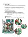
[1] AVR VOLTAGE
Output voltage of Automatic Voltage Regulator circuit can be measured and adjusted as follows.
If AVR voltage has been adjusted, tube current must be adjusted after that.
1. Prepare a digital multimeter capable to measure 200 Vac with 1 % or more accuracy.
2. Turn off the main switch. Set the suitable range of digital multimeter to measure 200 Vac.
3. Open the front panel of the main controller and place one lead of multimeter to JP3-2 on the
power PCB and other lead of multimeter to "TP2" a wire ring test terminal on the power PCB.
(Refer to FIGURE 4A.)
4. Turn on the main switch on the main controller.
5. Depress the T2, T3 and P (patient) switches on the sub controller simultaneously until the letters
"Adj" appears in the exposure time display window.
6. Sellect 7mA and press the exposure switch to get a reading. It should be 180Vac ± 1Vac.
NOTE : TO PREVENT OVERHEATING OF THE FILAMENT, RELEASE THE
EXPOSURE SWITCH AS SOON AS POSSIBLE AFTER THE VOLTAGE
VALUE IS OBTAINED.
7. If the AVR voltage is higher than this range, adjust VR1, a pot at center of PCB, counterclockwise
very slightly and repeat step 6 to get reading. Repeat until an AVR voltage setting becomes
within the range of 180 ± 1Vac.
CAUTION : MAKE SURE 7 mA IS SELECTED. IF 4 mA IS SELECTED,
VOLTAGE IN STEP #6 IS TOO HIGH AND HEAD WILL BE DAMAGED.
JP3-2
VR1
FIGURE 4A. JP3-2 and TP2 on Power PCB
-18-
TP2
Alternative method to adjust AVR voltage
Adjusting method of AVR voltage on page requires the tube head to be connected. If by
any reason AVR voltage should be adjusted without head, following method can be used. In this
method the reference voltage for AVR circuit is adjusted.
1. Prepare a digital multimeter capable to measure 10 Vac within ±0.01Vac accuracy.
2. Set the range of digital multimeter at 10Vac.
3. Turn off the main switch . Open the front panel of the main controller and connect one lead of
multimeter to "TP3" a wire ring test terminal on the power generating PCB. Connect the other
lead of multimeter to "TP2" test terminal on the power generating PCB. (Refer to FIGURE 4B.)
4. Turn on the main switch and select 7mA.
CAUTION : MAKE SURE 7 mA IS SELECTED. IF 4 mA IS SELECTED,
VOLTAGE IN STEP #5 IS TOO HIGH AND HEAD WILL BE DAMAGED.
5. Voltage reading should be within the range of 7.28∼7.32 Vac at 7mA setting.
6. If the voltage is out of this range, then adjust VR1, a pot near the TP3 test terminal, very slightly
to make the voltage reading within 7.28∼7.32 Vac.
TP3 and VR1
TP2
FIGURE 4B. TP2, TP3 and VR1 on the Power Generating PCB
-191
[2] INSPECTION OF TUBE CURRENT
Belray II 097 has two types of self measuring function for tube current, i.e., auto mode
and manual mode. Tube current can also be measured directly by multimeter.
In auto mode, both tube current at the beginning and stabilized period of exposure are checked
and adjusted automatically, although the values of tube current are not displayed.
In manual mode, the value of tube current is displayed at the exposure time display window,
but additional operations are necessary to adjust the tube current.
In case of two methods mentioned above, tube current is measured by the micro computer on
the power generating PCB.
Last method is direct measurement of voltage. Tube current is converted into voltage by
resistor R37 and R38 (totally 500Ω) on power generating PCB. The voltage across these resistor
becomes 3.5 Vdc, when tube current is 7 mAdc. In this method, the tube current only at
stabilized period of exposure can be measured.
Auto mode is recommended for post installation confirmation and periodic maintenance.
a. Auto mode
1. Turn on the main power switch .
2. Depress the tooth selection switches T1, T4 and T5 together until 4mA light blinks.
3. Exposure time "0.50" is displayed and ready light is on. (If not, turn off main power switch
and repeat step 2.) Then release T1, T4 and T5 switches.
4. Make an exposure by depressing the exposure switch.
WARNING : X-RADIATION IS GENERATED FOR 0.5 SECONDS.
5. If "h.XX" and "e.XX" are displayed alternately after the exposure, leave the unit for about 30
seconds until the display returns to "0.50". Then make another exposure again.
6. If "Fin" is displayed at the exposure time display window, tube current at the beginning of
exposure and tube current at the stabilized period of exposure are within the specifications for
both 4mA and 7mA.
7. Repeat step 5. until "Fin" is displayed.
b. Manual mode
Model 097 x-ray has the function displaying the tube current of the first pulse and the last pulse
of the exposure at the exposure time display window. By this function, the tube current at the
beginning and at the stabilized portion of the exposure can be measured.
1. Power on the control box.
2. Set the exposure time at 0.5 seconds by the manual adjusting switch next to the exposure time
display window.
3. Make an exposure and keep the exposure switch depressed even after the exposure is over.
Press the mA selection switch either 4 mA or 7 mA.
4. T1 tooth light comes on and tube current of the first pulse of the exposure is displayed at the
exposure time display window, while the exposure switch is depressed.
5. Keep depressing the exposure switch, press the mA selection switch again. Then T5 tooth light
comes on and tube current of the last pulse of the exposure is displayed at the exposure time
display window. This value is tube current at the stabilized portion of the exposure.
6. If tube current of the first pulse is out of ±2 mA from the rated current, perform the h.XX
adjustment. If tube current of the last pulse is out of ±1 mA from the rated current, perform
the e.XX adjustment.
-20-
c. Direct measurement
1. Prepare a multimeter capable to measure 5 Vdc with 1% accuracy within 1 second.
2. Turn off the main switch.
3. Open the front panel of main controller.
4. Set to the suitable range of multimeter to measure 5Vdc.
5. Connect the positive lead of multimeter to test point TP1 at lower left corner on the power PCB
and negative lead to the test point TP6 at upper left corner on the power PCB.
6. Turn on the main switch.
7. Set the exposure time to 2 seconds.
8. Make exposure and read the multimeter during exposure.
WARNING: X-RADIATION IS GENERATED FOR 2 SECONDS.
9. Multiply the voltage reading by 2 becomes tube current. Ex. If reading is 3.45 Vdc, then tube
current is 3.45×2 = 6.9 mA. This value is the tube current at the stabilized portion of the
exposure. (By this method, tube current at the beginning of exposure cannot be measured.)
[3] ADJUSTMENT OF TUBE CURRENT
Tube current at beginning of exposure can be adjusted by h.xx setting and tube current at
stabilized portion of exposure can be adjusted by e.xx setting.
If tube current is checked by auto mode as mentioned on page 20 and if tube current is out of
range, successive exposure sets h.xx and e.xx to adequate value automatically.
If tube current is checked by manual mode as mentioned on page 20, h.xx and e.xx should
be adjusted manually as follows.
(1) MANUAL SETTING METHOD FOR h.xx
1. Check tube current at beginning of exposure by manual mode as page 16. If tube current is out
of the range of ±0.5 mA from the rated current, perform following adjustment.
2. Turn on the main switch.
3. Keep depressing P (patient), C (cone), F (film) button until "h.xx" is displayed on the exposure
time window.
4. Select the tube current that should be adjusted.
5. If tube current is lower than -0.5 mA at step 1, press ▲ switch next to the exposure time display
window and h.xx value displayed will be increased. If tube current is higher than +0.5 mA,
press ▼ switch and decrease the h.xx value displayed. xx has 32 kinds of values, 00∼1F.
Next to 9 is A and consequently F equals to 15.
6. Press the patient switch to memorize the h.xx value displayed to the memory. If value is stored,
electronic chime will should twice.
7. Turn off the main switch and check the tube current at beginning of exposure again. If tube
current is within ±0.5 mA from the selected current, PH adjustment is finished. If tube current
is still out of the range, repeat step 2∼6 above.
(2) MANUAL SETTING METHOD FOR e.xx
1. Check tube current at stabilized portion of exposure by the manual mode (page 20) or by the
direct measurement (page 21). If tube current is out of the range of ±0.5 mA from the rated
tube current, perform following adjustment.
2. Turn the main power switch.
-21-
3. Keep depressing P (patient), C (cone), F (film) button until "e.xx" is displayed on the exposure
time window.
4. Select the tube current that should be adjusted.
5. Press T2 switch then display changes to "e.xx". xx is the value presently memorized.
6. If tube current is lower than -0.5 mA from the rated tube current at step 1, press ▲ switch next to
the exposure time display window and e.xx value displayed will be increased. If tube current is
higher than +0.5 mA, press ▼ switch and e.xx value displayed will be decreased. e.xx has
32 kinds of values.
7. Press the patient switch to memorize the e.xx value displayed to the memory. If value is stored,
electronic chime will should twice.
8. Turn off the main switch and check the tube current at stabilized portion of exposure again. If
tube current is within ±0.5 mA from the selected tube current , e.xx adjustment is finished. If
tube current is still out of the range, repeat step 2∼7 above.
[4] ADJUSTMENT OF LINE VOLTAGE MEASUREMENT ERROR
Line voltage is monitored by micro computer and if it is out of the operable range (90∼100%
of the rated voltage), the ready lamp on front panel becomes off and exposure is inhibited. The
form of line voltage is a sine wave. Since the peak voltage of this sine wave is converted to
measurable voltage and apply to micro computer, there exists a measurement error if the wave form
is not perfect sine wave.
If measured RMS (Root Mean Square) voltage of power line by a precise multimeter is within
the range of 90∼100% of the rated line voltage, but the ready lamp on front panel doesn't come up,
measured voltage by micro computer can be shifted ±3 % as follows.
1. Turn on the main switch.
2. Keep depressing T2, T3 and T4 switches until "Pc.x" is displayed on the exposure time window.
3. Meaning of Pc value is as follows.
Pc.0 : No compensation is applied. ← initial setting from factory
Pc.1 : Measured voltage by micro computer is decreased by 3 %.
Pc.2 : Measured voltage by micro computer is increased by 3 %.
4. If multimeter indicates 107∼110% of rated line voltage and ready lamp doesn't comes on, set to
"Pc.1" by depressing ▲ switch next to the exposure time display window.
5. If multimeter indicates 90∼93% of the rated line voltage and ready lamp doesn't comes on, set to
"Pc.2" by depressing ▲ switch next to the exposure time display window.
6. After the display becomes suitable value, press the patient switch to store the value in the memory
on timer PCB. If the setting is stored, electronic chime will sound twice.
7. Turn off the main switch and wait for a while and turn on again.
8. If the ready lamp is still off although the multimeter indicates 90∼110% of the rated line voltage,
the wave form of line voltage is far from sine wave more than 3% or transformer on the power
generating PCB or timer PCB might be defective.
-22-
SECTION 5 : PERIODIC INSPECTION AND ADJUSTMENT
Following inspections and adjustments should be performed after installation, when parts are
changed, and once every 6 months by a trained service technician to ensure that the x-ray unit is
functioning with the manufacturer's specifications and remains in compliance with the standard.
[1] ELECTRICAL INSPECTION AND ADJUSTMENT
(1) POWER SUPPLY VOLTAGE
Power supply voltage must be within the operable range (90∼110% of rated line voltage).
Confirm the power supply voltage before turning the unit on.
1. Open the front panel of control box by loosening two screws on top of control box.
2. Set the range of digital multimeter at 300Vac, connect probes of multimeter to L and N terminals
of terminal block in the control box.
3. Confirm that the reading is rated line voltage±10%.
(2) CONFIRMATION OF TUBE CURRENT
Confirm the tube current at beginning and at stabilized portion of exposure by auto mode as
page 16.
(3) EXPOSURE WARNING BUZZER AND LAMP
a. Exposure warning buzzer
Make an exposure and confirm that the exposure warning buzzer located within the control box is
activated during the entire exposure.
b. Exposure warning lamp
Make an exposure and confirm that the exposure warning lamp illuminates during the exposure.
Exposure warning lamp is located on the front panel of the control box.
(4) LINE VOLTAGE REGULATION
1. Make sure that a main power switch is "OFF".
2. Open the front panel of control box by loosening two screws on top of the control box.
3. Set the range of digital multimeter at 300Vac, connect probes of multimeter to L and N terminals
of terminal block in the control box.
4. Turn the main power switch on, and select 7mA and set the exposure time at 2.00 seconds by ▲
switch next to the exposure time display window.
5. Record the no load line voltage (VN) indicated by the multimeter before the exposure.
6. Make an exposure and record the load voltage (VL) indicated by the multimeter during the
exposure.
WARNING: X-RADIATION IS GENERATED FOR 2 SECONDS.
NOTE: Read the multimeter after the value is stabilized (about one second after the exposure
starts.)
7. Calculate line voltage regulation R (%) in the formula below.
R = (VN−VL) / VL ×100
R must not exceed the range of 0∼2%. If it is greater than 2%, the size of the power supply
wires must increased. Refer to the power supply requirements of the model 097 installation
instructions to determine the correct wire size necessary.
-23-
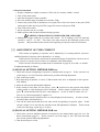
[2] MECHANICAL INSPECTION
(1) ARM ASSEMBLY
1. Incorrect leveling of the wall plate and wall bracket can cause arm drift. First, check leveling with
horizontal arm in position #1. (FIGURE 5) If not correct, bracket must be adjusted by placing
shims behind the wall plate.
IMPORTANT :
If the end of the horizontal arm shown in position #1 is pitched below level, then the tube head
will drift away from the wall. If the end of the horizontal arm in position #1 is pitched above
level, then the arm will require only minimum adjustment of the brake screw.
2. Check leveling in position #2. if not correct, adjust
Horizontal Arm as follows : (FIGURE 5)
a. Slightly loosen two top mounting bolts for arm
mounting bracket.
b. Shift the bracket left or right until the arms are
accurately leveled.
c. Move the horizontal arm to position # 1.
d. Fully tighten two top mounting bolts.
e. Fully tighten bottom mounting bolt.
FIGURE 5.
NOTE : Slight tendencies to drift can be corrected
by tightening brake screw in horizontal arm.
Do not tighten beyond what is required to
prevent drift.
(2) BALANCE ARM TENSION ADJUSTMENT
1. Place the balance arm assembly into position.
2. If either balance arm drifts higher or lower from
the set position, remove the spring adjuster cover
and adjust the balance arm spring tension with
the balance arm wrench. (FIGURE 6)
(3) HEAD POSITIONING
A. Place head into position.
B. If head drifts from the set position, adjust the brake
screws according to the following procedures.
(FIGURE 7)
1. Loosen the yoke side cap screw (ø3 x 8mm
tapping screw) and remove the yoke side cap.
2. Adjust the six brake screws using a screw driver.
3. After adjustment, reattach the yoke side cap and screw.
FIGURE 6.
FIGURE 7.
(4) MECHANICAL SAFETY
1. The wall plate, if used, should be checked to confirm its secure attachment to the wall.
2. The arm mounting bracket should be checked to confirm its secure attachment to the wall
mounting plate or, to the wall.
3. Check to insure the horizontal arm is not raising up and out of the arm mounting bracket. This
should be observed routinely by treatment room personnel.
-24-
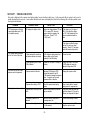
SECTION 6 : ERROR CODE
When abnormal condition exists in the unit, or malfunction occurs, error code is displayed in exposure time display window. Possible causes,
check points and solutions for each error code are described below.
CODE
E.00
MEANING
Exposure switch is released
before the exposure
terminates.
POSSIBLE CAUSE
a. Operator's fault.
b. Exposure switch or the coil cord
for exposure switch is defective.
E.01
Exposure switch is
depressed within 10 sec.
from the previous exposure.
Operator's fault.
E.02
Line voltage is less than 90
% of rated voltage.
a. Line voltage is less than 90% of
E.03
Line voltage is more than
110% of rated voltage.
CHECK POINT
SOLUTION
Instruct operator to release the
exposure switch after the exposure
lamp turns off.
Disconnect the exposure switch form
the sub-controller and check the
continuity during the exposure switch
is on.
If defect is found, exchange the
exposure switch and cord.
Instruct operator to take a "wait"
interval of 50 times of exposure
time between two successive
exposures.
Measure the incoming voltage between
terminal L and N of terminal block in
the control box.
If line voltage is less than 90% of the
rated voltage, correct the voltage
with additional step-up transformer.
b. Wave form of line voltage is differ
from sine wave.
Measure the incoming voltage between
terminal L and N of terminal block in
the control box.
If line voltage is close to 90% of
rated voltage but over 90%, set
PC.x setting to PC.2. (Press T2·
T3·T4 and power switch for PC.x
setting mode.)
a. Line voltage is more than 110% of
Measure the incoming voltage between
terminal L and N of terminal block in
the control box.
If line voltage is more than 110% of
rated voltage, correct the voltage
with additional step-down transformer.
Measure the incoming voltage between
terminal L and N of terminal block in
the control box.
If line voltage is close to 110% of
the rated voltage but less than 110%,
set PC.x to PC.1. (Press T2·T3·T4
and power switch for PC.x setting
mode.)
the rated voltage.
the rated voltage.
b. Wave form of line voltage is differ
from sine wave.
-25-
CODE
MEANING
POSSIBLE CAUSE
E.04
Excess line current during
exposure.
a. Tube head is internally shorted.
Disconnect the tube head and make
an exposure.
If E.07 comes, the tube head may
be defective. Change the tube head.
b. Cables between the control box
and head are short circuited.
If E.04 still comes when the tube head
is disconnected, disconnect the wires
from the power PCB (CN4 and CN5)
and make an exposure.
If E.07 comes, cables between
the control box and head may be
short circuited. Find the defective
portion and correct it.
c. Power PCB is defective.
Disconnect the wires from power
PCB (CN4 and CN5) and make
an exposure.
If E.04 still comes, power PCB may
be defective. Change the power
PCB.
AVR voltage is too low.
Measure the voltage between TP2 and
JP3-2 on the power PCB when the
exposure switch is pressed in the
"Adj" mode. (Press P·T2·T3 for
"Adj" mode.)
If the voltage is out of range of
180 ± 1 Vac, adjust the voltage
to 94.5Vac by VR1 on the power
PCB. After adjustment, tube
current confirmation should be
done.
Measure the voltage between TP2 and
TP3 on the power PCB at 7mA setting.
If the voltage is out of range of
7.30 ± 0.02Vac, adjust the voltage
to 7.30Vac by VR1 on the power
PCB. After adjustment, tube
current confirmation should be done.
E.05
Tube current of the last
pulse is less than 3mA at
4mA setting or less than
5.25mA at 7mA setting.
CHECK POINT
SOLUTION
E.06
Tube current of the last
pulse is more than 5mA at
4mA setting or more than
8.75mA at 7mA setting.
AVR voltage is too high.
Refer to CHECK POINT of E.05
Refer to SOLUTION of E.05
E.07
Tube current during
exposure is less than 2mA
at 4mA setting or less than
3.5mA at 7mA setting.
a. AVR voltage is too low.
Refer to CHECK POINT of E.05
Refer to SOLUTION of E.05
b. Cables between the control box
and head are broken or mis-wired.
Check each cables for continuity and
mis-wiring.
Correct the cable.
c. Power PCB is defective.
If all cables are OK and AVR voltage
cannot be adjusted to 180Vac or
TP2 and TP3 voltage cannot be
adjusted to 7.30 Vac at 7mA setting,
power PCB may be defective.
Change the power PCB and check
AVR voltage or TP2 - TP3 voltage
again.
d. Defect of tube head. (Filament
damage.)
If AVR voltage and cable are all right,
tube head may be defective.
Change the tube head and confirm
the function again.
-26-
CODE
MEANING
E.08
Tube current during
exposure is more than
6mA at 4mA setting or
more than 10.5mA at
7mA setting.
POSSIBLE CAUSE
CHECK POINT
SOLUTION
a. AVR voltage is too high.
Refer to CHECK POINT of E.05
Refer to SOLUTION of E.05
b. Cables between the control box
and head are broken or mis-wired.
Check each cables for continuity and
Mis-wiring.
Correct the cable.
c. Power PCB is defective.
If all cables are OK and AVR voltage
cannot be adjusted to 180Vac or
TP2 and TP3 voltage cannot be
adjusted to 7.30 Vac, power PCB
may be defective.
Change the main PCB and check
AVR voltage or TP2 - TP3 voltage
again.
d. Defect of tube head.
(Internal short)
If AVR voltage and cable are all right,
then tube head may be defective.
Change the tube head and confirm
the function again.
E.09
Malfunction of the microcomputer.
Memory setting for lower limit of line
voltage is higher than the higher limit
of line voltage.
Check the L.xx value and H.xx
values in the line voltage limit setting
mode. (Press T1·T3·T5 and power
switch for this mode.)
If L.xx is higher than H.xxx,
adjust these settings. (Refer to the
solutions for possible cause "c" of
E.02 and E.03. If these values
cannot be adjusted, display PCB
may be defective.
E.10
Exposure switch or exposure
switch circuit is ON, when
main power switch is turned
ON.
Exposure switch or the coil cord for
exposure switch is defective.
Turn off the main switch and disconnect
form the timer PCB. Turn on the
main switch again.
If E.10 does not appear, change
the exposure switch or coil cord for
exposure switch.
E.11
Tube current is detected
during pre-heating period.
High voltage is applied to x-ray tube
during pre-heating period.
Turn off the main switch and wait for a
while. Turn on the main switch again.
If E.11 still appears, change the
power PCB.
E.12
Tube current is detected,
when main power switch is
turned ON.
Both relay and triac are broken
or MA feedback circuit is defective.
Turn off the main switch and wait for a
while. Turn on the main switch again.
If E.12 still appears, change the
power PCB.
E.22
Failure of communication
between power PCB and
time PCB.
Any switch on the subcontroller is depressed
when the power switch is
turned on.
Electrical noise makes miscommunication.
Turn off the main switch and wait for
If E.22 still appears, check the
Approximately 2 min. Turn on again. cable between the PCBs.
Some switch on the timer PCB
is defective.
Turn off the main switch and wait for
If E.23 still appears, change the
Approximately 2 min. Turn on again. Timer PCB.
E.23
If E.10 still appears, change the
timer PCB.
-27-
SECTION 7 : TROUBLE SHOOTING
Error code is displayed in the exposure time display window for most troubles in daily usage. So the error code table in section 6 can be used as
trouble shooting chart in most case. Some troubles that don't make error code displayed are listed in the following table with their possible causes,
check points and solutions.
PROBLEM
1. "FIN" doesn't appear in the tube
current confirmation mode. (P.19
of installation manual)
POSSIBLE CAUSE
AVR voltage is too high or too low.
CHECK POINT
Measure the voltage between TP2 and
JP3-2 on power PCB, when the
exposure switch is pressed in the
"Adj" mode. (Press P·T2·T3
for "Adj" mode.)
SOLUTION
If the voltage is out of range of
180±1Vac, adjust the voltage
by VR1. After adjustment, tube
current confirmation should be
done.
If the voltage is within the range,
set final h.xx and e.xx values
manually. (Press P·C·F and power
switch for manual setting mode.)
2. AVR voltage cannot be adjusted
to 94.5 Vac in the "Adj" mode.
3. Exposure does not start when
exposure switch is depressed.
4. Radiograph is too dark or too light.
a. Cables between the control box
and head are broken or mis-wired.
If AVR voltage is staying around line
voltage, cables may be broken.
(especially #3 and #5 cables)
Correct the cable.
b. Power generating PCB or timer
PCB is defective.
If cables are OK, either PCB may be
defective.
Change the power PCB first and
if AVR voltage still cannot be
adjusted, change timer PCB.
a. Exposure switch is defective.
Disconnect CN2 from timer PCB
and short the terminal #1 and #3
of CN2 instead of pressing the exposure
switch. If exposure can be made,
exposures switch is defective.
Change the exposure switch.
b. Exposure time setting is "0.00".
Check the exposure time display
window.
Press a tooth switch or manual
setting switch for exposure time.
a. Exposure time is too long or too
short.
Check the tooth, patient, cone and film
type are adequate.
Proper tooth, patient and cone type
should be selected. If film type is
different, set adequate film speed.
b. Processing condition is not
adequate.
c. Tube current is too high or too low.
Check the solution, temperature or
processing speed, etc.
Check the tube current. (Refer to page
16 of this manual.)
Correct the processing condition.
-2824
If tube current is out of ± 0.5mA,
adjust h.xx and e.xx value.
SECTION 8 : REPLACEMENT OF COMPONENT
[1] CONTROL BOX
(1) POWER GENERATING PCB
1. If one or more results of verification checks are out of specification or trouble shooting chart
indicates, power generating PCB should be replaced.
2. Since power MOS FETs and C-MOS micro computer chips are used, great care should be paid
against electrostatic discharge (ESD).
a. Personnel who handle PCB should touch the grounding screw (green/yellow wire) in the control
box and discharge the static electricity from his body before working.
b. Replaced PCB should be stored in the anti-static bag.
(2) TIMER PCB
1. If one or more results of verification checks are out of specification or trouble shooting chart
indicates, timer PCB should be replaced.
2. Since micro computer on the timer PCB is C-MOS type, same care as power generating PCB
should be paid against ESD.
3. Since screws are used against plastic panel, don’t over tighten when installing a new PCB.
4. After new timer PCB is installed, following confirmation, adjustment and setting must be
per-formed. If the setting of b.~d. below is not changed from factory setting for the previous
timer PCB, only a. is necessary. (a is always necessary.)
a. Tube current confirmation and adjustment.
b. Film speed setting.
c. Priority setting for patient, cone and film speed.
d. Electronic chime on/off setting
[2] TUBE HEAD
1. If one or more results of verification checks are out of specification or trouble shooting chart
indicates, tube head should be replaced.
2. When dismounting the head from arm, be careful of the arm.
WARNING : AS BALANCE ARM IS HIGHLY TENSIONED, IT IS NECESSARY TO
PLACE THE HEAD AT MAXIMUM HEIGHT BEFORE REMOVING
HEAD.
3. After new head is mounted, adjustment of tube current is always necessary. Perform h.xx and
e.xx adjustment according to the steps described at auto mode on page 19.
-29-
SECTION 9 : CIRCUIT DIAGRAM
-30-
NOTE
R
TAKARA BELMONT CORPORATION
2-1-1,Higashishinsaibashi,Chuo-ku,Osaka,542-0083,Japan
TEL. : (06)6213-5945
FAX. : (06)6212-3680
Book No.1A091AA0
Printed in Japan
2011-10 TM