1
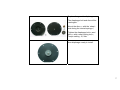
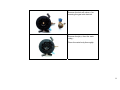
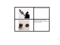
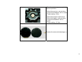
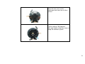
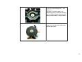
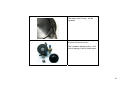
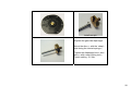
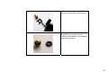
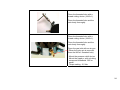
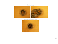
REDUCER SERVICE MANUAL
VERDAMPER REVISIE HANDLEIDING
VERDAMPFER REVISION ANLEITUNG
2009-10-12
REDUCER SERVICE
Tools and products:
•
•
•
•
•
•
•
•
•
•
•
•
Reducer replacement kit 180/10020
Reducer replacement kit 180/10025H
Allan key 4 mm
Thread cutting device M10x1
Ring spanner size 8 mm / 16 mm / 17 mm
Torque spanner ( 0 -10 Nm ) with socket 14 mm / 8 mm
14 mm socket with ratchet
Special 19 mm socket ( part nr. 099/9980 ) with ratchet ( for H-reducer )
Screwdriver ( flat head )
Hammer
Air gun
Brake cleaner / carburettor cleaner
Reducer parts not sold separately
C-D-E reducer :
H-reducer :
page 3 - 16
page 17 - 29
Damper modification in J-reducer : page 30 - 38
Testing / Calibrating :
page 39 - 42
2
Reducer replacement kit 180/10020 :
- Gas-side diaphragm(4)
- Water-side diaphragm(5)
- Pressure relief valve O-ring(29)
- Locking nut M5(11)
- Jet(15)
- Locating pin(14)
- 3 pipes with 6 O-rings
- Valve seat(16)
Loosen the six Allen screws(18).
NOT the “Tensilock-nuts”(33),
otherwise they will loose their locking
function.
3
Remove the six Allan screws(18).
Use the recess in the diaphragms to
separate the covers from the main
body (1).
4
Remove the rear cover(2).
The valve spring(17) will be used
again.
Remove the water-side diaphragm(5)
from the rear cover(2).
The water-side diaphragm(5) will be
replaced.
Replace all the plastic pipes with orings.
Remove the valve seat(16) and the
locating pin(14).
5
The valve seat(16) and the locating
pin(14) will be replaced.
Remove the front cover(3).
The complete adjusting disc(7) and
conical spring(10) will be used again.
6
Replace the gas-side diaphragm.
The diaphragm bolt and disc will be
used again.
Mount the disc(12) with the ‘sharp’side facing the conical spring(10).
Tighten the diaphragm bolt(13) and
disc(12) with a new locking nut(11).
Torque setting : 2,5 Nm.
New diaphragm ready to install.
7
Remove the lock-off valve(31) for
cleaning the gas inlet channel.
Remove the jet(15) from the main
body(1).
Clean the main body thoroughly.
8
Remove the pressure relief device.
Replace the o-ring(29) from the
pressure relief valve(24) and replace it
with a new o-ring(29).
9
Clean the threaded hole with a
thread cutting device ( M10x1 ).
Clean the threaded hole and the
main body thoroughly.
Clean the threaded hole with a
thread cutting device ( M10x1 ).
Clean the threaded hole and the
main body thoroughly.
Clean the gas inlet with an air gun.
( When the valve pin is removed,
clean the M10x1 threaded hole).
10
When the main body(1) is completely
free from pollution :
- Mount the new jet(15) wit a locking
compound threebond 1305 or equal
Torque setting : 4 Nm
- Mount the pressure relief device.
Mount the nipple(22) with a locking
compound threebond 1305 or
equal.
Torque setting : 2,5 Nm
Replace the water-side diaphragm (5)
11
Install the new valve seat(16) with the
rubber compound facing the jet(15).
Install the spring(17) on the new valve
seat(16).
Install the new water-side
diaphragm (5) on the back of the main
body (1).
Make sure the valve spring (17) is in
position on the valve seat (16).
12
Place the rear cover on the
diaphragm and insert the six Allan
screws.
Flip the reducer 180 degrees.
Use one hand on the rear cover to
keep the screws in place.
13
Insert the new locating pin(14) into
the jet (15).
To check if the valve seat(16) is
installed properly, press the locating
pin. The valve seat and location pin
will be pushed back in start position.
Install the new gas-side diaphragm
on the main body.
14
-
Front cover(3)
Pressure adjusting disc(7)
Conical spring(10)
Install the disc and spring into the
front cover.
Use the drive-in screw (8) for
positioning the disc (7) in the cover.
Without the drive-in screw, the
pressure can not be adjusted.
15
Install the front cover on the main
body.
Tighten the Allen screws and NOT
the “Tensilock-nuts”, otherwise they
will loose their locking function.
Torque setting : 8 Nm.
Test the reducer for proper
functioning according the test
procedure.
16
H-reducer : Reducer replacement kit 180/10025H
17
Remove the six Allan screws(18).
separate the covers from the main
body (1).
Remove the rear cover(2).
The water-side O-ring(5) will be
replaced.
Replace all the plastic pipes with orings.
18
The water-side O-ring(5) will be
replaced.
Remove the front cover(3).
The complete adjusting disc(7) and
conical spring(10) will be used again.
19
install new pin
Replace the gas-side diaphragm.
Mount the disc(12) with the ‘sharp’side facing the conical spring(10).
Tighten the diaphragm bolt(13) and
disc(12) with a new locking nut(11).
Torque setting : 2,5 Nm.
20
New diaphragm ready to install.
Remove the lock-off valve(31) for
cleaning the gas inlet channel.
21
Remove the jet(15) from the main
body(1).
Special 19 mm socket ( part nr.
099/9980 )
Clean the main body thoroughly.
Remove the lock compound pollution
Remove jet, valve and spring.
Clean the main body thoroughly.
Remove all parts of the locking
compound.
22
Remove the pressure relief device.
Replace the o-ring(29) from the
pressure relief valve(24) and replace it
with a new o-ring(29).
23
Clean the threaded hole with a
thread cutting device ( M10x1 ).
Clean the threaded hole and the
main body thoroughly.
Clean the threaded hole with a
thread cutting device ( M10x1 ).
Clean the threaded hole and the
main body thoroughly.
Clean the gas inlet with an air gun.
( When the valve pin is removed,
clean the M10x1 threaded hole).
- Mount the pressure relief device.
Mount the nipple(22) with a locking
compound threebond 1305 or
equal.
Torque setting : 2,5 Nm
24
1
2
3
insert spring into cleaned body and
cleaned threaded center.
new valve
NOT TO MUCH locking compound !!
Otherwise the compound can glue the
valve against the jet.
4
When the main body(1) is completely free
from pollution :
- Mount the new jet(15) wit a locking
compound threebond 1305 or equal
tighten the new jet
Torque setting : 4 Nm
25
Place the rear cover with the new Oring and insert the six Allan screws.
Flip the reducer 180 degrees.
Use one hand on the rear cover to
keep the screws in place.
26
Insert the new locating pin(14) into
the jet (15).
To check if the valve seat(16) is
installed properly, press the locating
pin. The valve seat and location pin
will be pushed back in start position.
Install the new gas-side diaphragm
with the new locating pin(14) into the
jet (15).
To check if the valve seat(16) is
installed properly, press the locating
pin. The valve seat and location pin
will be pushed back in start position.
27
-
Front cover(3)
Pressure adjusting disc(7)
Conical spring(10)
Install the disc and spring into the
front cover.
Use the drive-in screw (8) for
positioning the disc (7) in the cover.
Without the drive-in screw, the
pressure can not be adjusted.
28
Install the front cover on the main
body.
Tighten the Allen screws and NOT
the “Tensilock-nuts”, otherwise they
will loose their locking function.
Torque setting : 8 Nm.
Test the reducer for proper
functioning according the test
procedure.
29
Damper modification in J-reducer
Loosen the six torx screws. Do NOT rotate the “Tension lock-nuts”, otherwise they will loosen their locking function.
Remove the front cover, membrane and adjustment disc together with the spring.
30
Damper upgrade kit.
Take the piston of the upgrade kit.
31
Remove the locknut for the membrane.
Screw the piston onto the membrane using Threebond 1374 and tighten with 3.5 Nm torque.
32
Insert the membrane with needle back into the regulator.
Make sure that the needle is in its guidance clip underneath the membrane.
Take the adjustment bold that is in the upgrade kit and the adjustment disc with the spring.
33
Remove the spring.
Remove the locking clip with a screwdriver, make sure that you hold the locking clip, it can jump away.
34
Remove the old adjustment bold.
Insert the new adjustment bold into the disc.
35
Fit the locking clip.
Mount the spring back into place.
36
Insert the adjustment system into the top cover of the regulator.
Put the top cover onto the regulator.
37
Mount the tension lock-nuts and tighten the torx bolts with 8Nm torque.
No tightening
Tighten with 8Nm torque.
Install the regulator back on the car.
Adjust the pressure back to the original settings as seen in the parameter list and test the regulator for leakage and functionality.
38
How to Calibrate the test procedure
39
First steps before calibrating the test
1) Connect to the inlet air with a pressure of 5 bar abs.
2) Connect to the outlet a 16 mm hose with a pressure sensor, a manually operated valve and a restriction (1.0-2.0 mm orifice,
depending of the restrictions of the INLET).
3) If necessary connect a silencer on the outlet to reduce the noise.
4) Connect 12 Volts to the coil.
Calibrating the test:
Use a new reducer to calibrate the restriction on the outlet
1)
2)
3)
4)
The outlet pressure should be 2.1-2.2 bar (factory default)
When air is flowing through the reducer, monitor the outlet pressure value and close the valve on the outlet.
The pressure may increase maximal 0.15 bar.
If the pressure increases more than 0.15 bar decrease the restriction of the outlet.
40
Procedure for testing the reducer
41
Testing a reducer
1.
2.
3.
4.
5.
6.
7.
Connect to the inlet air with a pressure of 5 bar abs.
Connect to the outlet a 16 mm hose with a pressure sensor, a manually operated valve and a restriction
Connect 12 Volts to the coil.
Set the reducer to its maximum pressure (rotating adjusting bolt counter clockwise)
Pressure should be greater than 2.6 bar (abs).
When air is flowing through the reducer, monitor the outlet pressure value and close the valve on the outlet.
The pressure may increase maximal 0.15 bar, if the pressure keeps on rising, the reducer is leaking at the first stage
valve (reject the reducer).
8. Set the reducer to its minimum pressure (rotating adjusting bolt clockwise)
9. Pressure should be less than 1.6 bar (abs).
10. Set the reducer to 2.2 bar (abs) (factory default).
42