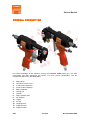
1
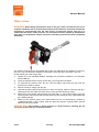
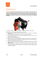
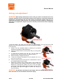
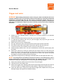
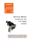
GAMA Deutschland GmbH
August-Thyssen-Straße 1
41564 Kaarst
Tel. + 49 / 21 31 / 1 76 88 92
Fax + 49 / 21 31 / 1 76 88 93
[email protected]
Service Manual
Projection Gun
evolution STAR
1st Issue 05/09/07
Ref. NR-00009-ENG
Before installing the evolution Star Gun and starting it up, carefully read
all the technical and safety documentation included in this manual. Pay
special attention to the information to know and understand the operation
and the conditions of use of the gun. All of the information is aimed at
enhancing User Safety and avoiding possible breakdowns derived from
the incorrect use of the Gun.
Service Manual
WARRANTY
GARRAF MAQUINARIA, S. A. (hereinafter “GAMA”) provides this LIMITED WARRANTY (hereinafter “Warranty”) to the
original purchaser (hereinafter “Customer”) covering this equipment and the original GAMA manufactured accessories
delivered with the equipment (hereinafter “Product”) against defects in material or workmanship of the Product
(hereinafter “Defect” or “Defective”) for a period of two (2) years from the date of first purchase as shown on the original
GAMA invoice (hereinafter “Warranty Period”).
If during the Warranty Period under normal use, the Product is suspected by Customer to be Defective in material or
workmanship, it is Customer’s responsibility to contact GAMA and return the Product to GAMA as directed by GAMA,
freight prepaid. If GAMA determines that the Product is Defective and that such Defect is covered by this Warranty,
GAMA will credit Customer for the reasonable freight charges incurred by Customer in returning the Defective Product
to GAMA, and GAMA (or its authorized agent) will, at GAMA’s option, repair or replace the Product, subject to the
following:
Original Invoice: The original invoice must be kept as proof of the date of first sale and the Product serial number. The
Warranty does not cover any Product if the Original Invoice appears to have been modified or altered, or when the serial
number on the Product appears to have been altered or defaced.
Product Maintenance: It is the Customer’s responsibility to maintain the Product properly. See your maintenance
schedule and owner’s manual for details. The Warranty does not cover an improperly maintained Product.
Non-GAMA Components and Accessories: Non-GAMA manufactured components and accessories that are used in the
operation of the Product are not covered by this Warranty. Such components and accessories shall be subject to the
warranty offered to the Customer, if any, by the original manufacturer of such component or accessory.
Other Warranty Exclusions: The Warranty does not cover any Product that GAMA determines has been damaged or
fails to operate properly due to misuse, negligence, abuse, carelessness, neglect, or accident. By way of example only,
this includes:
•
Normal wear an tear.
•
Improper or unauthorized installation, repair, alteration, adjustment or modification of the Product.
•
Use of heating devices, pumping equipment, dispensers, or other parts or accessories with the Product that
have not been approved or manufactured by GAMA.
•
Failure to follow the operating instructions and recommendations provided by GAMA.
•
Cosmetic damage.
•
Fire, flood, “acts of God,” or other contingencies beyond the control of GAMA.
THE WARRANTY DESCRIBED HEREIN IS THE EXCLUSIVE REMEDY FOR THE CUSTOMER AND IS IN LIEU OF ALL OTHER
WARRANTIES, EXPRESS, IMPLIED, STATUTORY OR OTHERWISE, AND THE IMPLIED WARRANTIES OF MERCHANTABILITY
AND FITNESS FOR A PARTICULAR PURPOSE AND ALL OTHER WARRANTIES ARE HEREBY DISCLAIMED. TO THE FULLEST
EXTENT PERMITTED BY LAW, GAMA SHALL NOT BE RESPONSIBLE, WHETHER BASED IN CONTRACT, TORT (INCLUDING,
WITHOUT LIMITATION, NEGLIGENCE), WARRANTY OR ANY OTHER LEGAL OR EQUITABLE GROUNDS, FOR ANY
CONSEQUENTIAL, INDIRECT, INCIDENTAL, LOST PROFITS, SPECIAL, PUNITIVE OR EXEMPLARY DAMAGES, WHETHER TO
PERSON OR PROPERTY, ARISING FROM OR RELATING TO THE PRODUCT, EVEN IF GAMA HAS BEEN ADVISED OF THE
POSSIBILITY OF SUCH LOSSES OR DAMAGES.
Non-Warranty Service by GAMA: If GAMA determines that the suspected Defect of the Product is not covered by this
Warranty, disposition of the Product will be made pursuant to the terms and conditions of GAMA’s written estimate on a
time and materials basis.
Continuing Warranty for Products Repaired or Replaced under Warranty: Following the repair or replacement of a
Product covered by this Warranty, such Product will continue to be subject to the original Warranty for the remainder of
original Warranty Period or for three (3) months from the repair or replacement date, whichever is longer.
No Rights Implied: Nothing in the sale, lease or rental of any Product by GAMA shall be construed to grant any right,
interest or license in or under any patent, trademark, copyright, trade secret or other proprietary right or material owned
by anyone; nor does GAMA encourage the infringement of same.
Exclusive Warranty: This writing is the final, complete, and exclusive expression of the Warranty covering the Product.
Any statements made by GAMA, its employees or agents that differ from the terms of this Warranty shall have no effect.
It is expressly understood that Customer’s acceptance of this Warranty, by performance or otherwise, is upon and
subject solely to the terms and conditions hereof, and any additional or different terms and conditions proposed or
expressed by Customer or anyone, whether in writing or otherwise, are null and void unless specifically agreed to in
writing by an Officer of GAMA.
2/25
1st Issue
Ref. NR-00009-ENG
Service Manual
All information provided in this Service Manual is assumed to be correct; although this does not
constitute any implicit or explicit liability or guarantee. GAMA reserves the right at any time and
without prior warning to make all improvements and modifications necessary to this Service
Manual, in order to rectify any possible typographical errors, supplement the information
contained or insert changes predicated by the performance or use of the Gun.
SAFETY AND HANDLING
This chapter contains important information on the safety, handling and use of your GAMA
evolution STAR series gun.
Before installing the Master gun and starting it up, carefully read all the
technical and safety documentation included in this manual. Pay special
attention to the information to know and understand the operation and the
conditions of use of the unit. All of the information is aimed at enhancing
User Safety and avoiding possible breakdowns derived from the incorrect
use of the gun.
WARNING! establishes information to alert on a situation that might cause serious
injuries if the instructions are not followed
PRECAUTION! establishes information that indicates how to avoid damage to the gun
or how to avoid a situation that could cause minor injuries.
NB: is relevant information on a procedure being carried out
Careful study of this manual will enable the operator to know the characteristics of the gun and
the operating procedures. By following the instructions and recommendations contained herein,
you will reduce the potential risk of accidents in the installation, use or maintenance of the gun;
you will provide a better opportunity for incident-free operation for a longer time, greater output
and the possibility of detecting and resolving problems fast and simply.
Keep this Service Manual for future consultation of useful information at all times. If you lose
this manual, ask for a new copy from your GAMA local distributor or directly contact Garraf
Maquinaria, S.A.
Important Safety Information
The evolution Star gun has been designed and built for the application of polyurea chemical
systems, polyurethane foam chemical systems and some two-component epoxy systems.
WARNING: The design and configuration of the gun do not allow its use in potentially
explosive atmospheres or the pressure and temperature limits described in the technical
specifications of this manual to be exceeded.
Always use liquids and solvents that are compatible with the unit. In the event of doubt, consult
the GAMA technical service.
3/25
1st Issue
Ref. NR-00009-ENG
Service Manual
When working with the gun, it is essential to wear suitable clothing and elements of personal
protection, including, without limitation, gloves, protective goggles, safety footwear and face
mask. Use breathing equipment when working with the gun in enclosed atmospheres or with
insufficient ventilation. The introduction and follow-up of safety measures must not be limited to
those described in this manual. Before starting up the gun, a rigorous analysis must be made of
the risks derived from the products to be dispensed, the type of application and the working
environment.
The gun forms part of the projection equipment, which is why the safety measures must be
adopted that are provided for the start-up and use of the equipment, in addition to those specific
to the use of the gun.
To prevent possible injury caused by incorrect handling of the raw
materials and solvents used in the process, carefully read the safety
instructions and recommendations provided by your product supplier.
Deal with the waste caused according to current regulations.
Disconnect the Unit from the power supply before carrying out any
operation inside the electrical console.
The electrical maintenance of the machine must only be performed by a
qualified electrician.
To avoid damage caused by the impact of pressurized fluids, do not open
any connection or perform maintenance work on components subject to
pressure until the pressure have been completely eliminated.
Use suitable protection when operating, maintaining or being present in
the area where the equipment is functioning. This includes, but is not
limited to, the use of a face mask, protective goggles, gloves, shoes and
safety clothing.
The equipment includes components that reach high temperatures and
can cause burns. Hot parts of the equipment must not be handled or
touched until they have cooled completely.
To prevent serious harm through crushing or amputations, do not work
with the equipment without the safety protections duly installed on the
moving parts. Make sure that all the safety protections are correctly fitted
at the end of the repair or maintenance work of the equipment
4/25
1st Issue
Ref. NR-00009-ENG
Service Manual
CHARACTERISTICS
The new gun series evolution STAR, with mechanical cleaning, has been designed for the
application of Polyureas, chemical systems for Polyurethane foaming and some two-component
Epoxy systems.
Its special configuration offers the possibility of adjusting the flow without having to change the
mix chamber and allows applications to be performed “in situ” and industrial applications with
great precision and maximum quality finish.
ESPECIFICACIONES
Maximum working pressure: ________________________ 70 Kgf/cm2 (6.9 MPa) / 1000 psi
Air pressure required: ________________________ 6-8 Kgf/cm2 (0.6-0.8 MPa) / 85-114 psi
Maximum production ratio 1:1: ________________________________ 8 Kg/min / 18 lb/min
Minimum production ratio 1:1: ________________________________ 1 Kg/min / 2.2 lb/min
Opening force @ 6 bar: ____________________________________________90 Kg / 200 lb
Closing force: _____________________________________________________40 Kg / 88 lb
Approximate air consumption @ 6 bar: ____________________________ 109 litres/minute
5/25
1st Issue
Ref. NR-00009-ENG
Service Manual
GENERAL DESCRIPTION
For better knowledge of the elements forming the evolution STAR series gun, the main
components and their description are shown. For more precise identification, see the
Components Manual ref. NR-00005-ENG.
1.
2.
3.
4.
5.
6.
7.
8.
9.
10.
11.
12.
13.
14.
6/25
Mixing block
Gun Block screen screw
A-check valve assembly
R-check valve assembly
Mixing Chamber
Valving rod
Cylinder
Spring retainer case
Air regulator
Trigger
Air Cap
Coupling block
A-Manual valve
R-Manual valve
1st Issue
Ref. NR-00009-ENG
Service Manual
INSTALLATION AND START-UP
PRECAUTION! When working with the gun or performing maintenance work on it,
wear suitable protection and follow the safety instructions and recommendations
provided by the product suppliers.
GAMA provides a series of tools and accessories that are necessary for assembling the gun.
The unit is made up of the following elements:
Metal brush, pipe spanner, chuck holder, pliers, spanner, kit of allen keys, hammer, pipe for
pneumatic connection, grease pipe, air pipe, fast socket, fast socket, chamber inserter,
chamber extractor, components manual and service manual.
1.
2.
3.
4.
Complete closure of manual valves by turning them clockwise. The manual valves control
the input flow of each product to the chamber and are located on the Coupling Block.
Connect the air supply pipe to the connector on the rear of the gun.
Connect the Isocyanate hose (red terminal) to the connection on the Isocyanate input
(letter A) in the Coupling Block.
Connect the Polyol hose (blue terminal) to the connection on the Polyol input (letter R) in
the Coupling Block.
NOTE: The product hoses have been distinguished with red and blue colors to allow
rapid identification. The red corresponds to the Isocyanate hose and the blue to the
Polyol hose. To avoid connection errors, the coupling connections of the Isocyanate and
Polyol hoses are different sizes, which makes it impossible to swap connections.
1.
2.
3.
Connect the air supply to the gun.
Check the position of the valving rod. With the gun at rest, the
valving rod must stand out approximately 1 mm from the front of the
chamber. If the measurement is not correct, perform the valving rod
adjustment by following the adjustment procedure specified in the
maintenance section.
Perform the valving rod adjustment in the shooting position as
indicated in the following:
a. Deactivate the spring retainer case and turn the valving
rod adjustment screw anticlockwise to the end,
unscrewing approximately 14 turns.
b. Remove one of the two check valve assembly on the
mixing block, on either side. Tighten the trigger and
insert the cleaning spatula in the groove where the
product passes into the chamber.
c. If the cleaning spatula passes easily, remove the
spatula, release the trigger and turn the valving rod
adjustment screw 1/2 a turn clockwise. Retighten the trigger and insert the
cleaning spatula once more in the groove where the product passes into the
chamber.
PRECAUTION! To avoid damage to the chamber, do not release the trigger with the
spatula in the groove where the product passes into the chamber.
7/25
1st Issue
Ref. NR-00009-ENG
Service Manual
4.
5.
d. Perform step “c” as many times as necessary until the cleaning spatula does
not pass through the groove where product passes into the chamber.
e. When the cleaning spatula does not pass through the groove, release the
trigger and turn the valving rod adjustment screw 1/4 a turn anticlockwise.
Retighten the trigger and insert the cleaning spatula once more in the groove
where the product passes into the chamber.
f. Perform step “e” as many times as necessary until the cleaning spatula passes
tightly through the groove where product passes into the chamber.
When the cleaning spatula passes tightly through the groove, remove the spatula, release
the trigger and turn the valving rod adjustment screw 1/4 a turn clockwise. Refit the check
valve assembly unit.
Tighten the locking screw and make sure that the valving rod regulation screw cannot be
turned with your hand.
NOTE: Periodically check the torque of the locking screw to guarantee the correct
positioning of the valving rod and avoid it moving while the gun is working.
6.
7.
8.
9.
10.
11.
12.
13.
14.
Check the air regulator. Turn it clockwise to have an air flow to
clean the remains of product there might be at the tip of the
chamber and the valving rod. Excessive air will distort the
projection fan. To completely close the air passage, turn
clockwise.
Make sure the torque of the lock nut of the chamber unit has the
right torque. Loosen it slightly, and tighten it slowly by hand until
you notice how it locks against the chamber seal, and using a
spanner, tighten a further 1/8 of a turn.
Insert the oil pan containing solvent in the holes of the lock nut
and wet the interior filter with gun-cleaning solvent.
Pull the trigger several times to make sure the valving rod moves
correctly.
Fit the seals of the coupling block in their place and fix it to the
mixing block of the gun.
Pressurize the unit and make sure there are no leaks.
Check that the pressure and the temperature of the hoses and
the heaters in the machine is correct (see the machine Service
Manual).
Open the manual valves of each product fully, by turning them
anti-clockwise.
Perform a test projection in a suitable vessel.
WARNING! To avoid accidents, always remove the coupling
block of the gun, close the manual valves of the two products and
disconnect the air supply before doing any maintenance work,
repairs or cleaning of the gun.
8/25
1st Issue
Ref. NR-00009-ENG
Service Manual
The gun is configured to have the air input in the rear. Optionally, it is possible to modify and
have the air at the base of the gun handle. To make the change, do the following:
1. Disconnect the air pipe from the rear.
2. Unscrew the connection of the rear of the gun.
3. Unscrew the existing cap on the base of the handle.
4. Screw the cap into the rear of the gun. Use Teflon tape or sealing paste to avoid air leaks.
5. Fit the air connection extension (optional) to the base of the handle. Use Teflon tape or
sealing paste to avoid air leaks.
6. Connect the air pipe.
The evolution STAR gun has been designed to work at a maximum
working pressure of 70 bar (1000 psi). Any exceeding of this pressure can
cause damage to the check valve assembly, cause internal faults in the
gun and expose the operator to risk situations.
9/25
1st Issue
Ref. NR-00009-ENG
Service Manual
Adjustment of the fan pattern
WARNING! Before performing any maintenance work in the gun, make sure the Unit is
at standstill, that all of the pushbuttons are off, that the general switch is in shutdown
position and that the equipment is disconnected from the main electricity supply. The
gun is a component that works under pressure; do not open any connection or do
maintenance work on components subject to pressure until all pressures have been
eliminated.
Having performed the steps indicated in the section on installation and start-up, proceed as
indicated in the following to adjust the projection fan:
Aim the gun at a suitable vessel and make short shots of approximately one second.
Observe the shape of the projection fan; if the valving rod has been adjusted correctly, it should
be round, if not, loosen the lock screw and turn the valving rod adjustment screw under 1/8 of a
turn clockwise to give the fan the correct shape.
PRECAUTION! Make sure not to turn the adjustment screw anticlockwise. The
movement of the valving rod behind the product input groove can cause material leaks
out of the rear of the chamber and cause problems in the gun operation.
If, despite the adjustments made, the projection fan is not completely round, make sure that the
product temperature and the working pressures are right.
If the fan remains closed, the temperature of the material is too low.
If the fan is irregular or has an empty centre, the temperature of the material is too high.
When you achieve the optimal projection fan, note the temperature of the heaters and the
working pressure hoses, and the position of the notch on the spring retainer case of the cylinder
with respect to the valving rod adjustment screw.
If any change should be seen in the shape of the fan during the projection, check the tip of the
chamber and eliminate and product remains with a wooden spatula or brass brush. If the
problem persists, remove the Air Cap and check that it is completely clean inside.
10/25
1st Issue
Ref. NR-00009-ENG
Service Manual
STANDSTILL METHOD
When stops of over 30 minutes are made, the check valve assembly units of each product must
be checked and cleaned, as well as the filter and the chamber unit (see the maintenance
section).
Do the following steps to guarantee correct operation:
1. Perform the Unit Standstill Method, following the procedure indicated in the Machine
Service Manual.
2. Close the manual valves of each product fully, by turning them clockwise.
3. To eliminate the pressure from the gun, pull the trigger and project the gun until the
projection fan starts to reduce.
4. Remove the coupling block from the gun.
5. Remove the check valve assembly of the polyol side in the mixing block . Clean the unit
and the housing with gun-cleaning solvent.
6. Remove the check valve assembly of the isocyanate side in the mixing block . Clean the
unit and the housing with gun-cleaning solvent.
7. Remove the filter-holder bolt. Clean the filter carefully with gun-cleaning solvent, making
sure that the mesh is completely free from product remains. Clean and dry the housing
thoroughly.
8. Tighten the trigger and hold it while cleaning the grooves where the product passes into
the chamber with gun-cleaning solvent.
9. Fit all of the components and fit the coupling block to the gun.
PRECAUTION! To avoid possible contamination by the product remains deposited in
the components of the gun, do not exchange the pieces of the Isocyanate with the pieces
of the Polyol. The gun has the Isocyanate side identified with the letter A.
If the product hoses maintain the pressure, follow the Standstill Method
indicated in the Machine Service Manual. To eliminate the pressure from
the hoses with the gun removed, fit the product input blocks in a suitable
container, keep a reasonable distance away and very carefully and very
slowly open the manual valves. With pressure, the product will come out
of the side of the blocks.
When you finish the working day, you must check the state of the valving rod (see maintenance
section). Complete the above mentioned steps “1” to “7” and do the following operations as
described in the following:
1. Disconnect the air supply.
2. Loosen the lock nut of the chamber unit 2 or 3 turns. Do not remove it.
3. Press the spring retainer case and turn it anticlockwise, remove the cylinder spring from
the inside.
4. Remove the valving rod by pressing hard on the cylinder axis until the stop nut of the
valving rod leaves the cylinder. If there is difficulty for removing the valving rod, turn on the
air supply, protect your hand with a leather glove and place it on the rear of the cylinder,
then press the trigger to remove the valving rod from its housing.
11/25
1st Issue
Ref. NR-00009-ENG
Service Manual
WARNING! Activating the gun trigger when the spring retainer case has been removed
can cause accidents with serious injury.
5.
6.
7.
Make sure there are no solid parts adhered to the valving rod and clean it with guncleaning solvent.
If the valving rod has remains of product on the rear, make sure that the filter inside the
lock nut is soft and soaked in solvent, and replace it if necessary.
Refit the gun.
12/25
1st Issue
Ref. NR-00009-ENG
Service Manual
MAINTENANCE
To obtain maximum output from your evolution STAR gun, it is necessary to periodically
perform certain maintenance operations.
To prevent possible injury caused by incorrect handling of the raw
materials and solvents used in the process, carefully read the safety
instructions and recommendations provided by your supplier.
Deal with the waste caused according to current regulations.
Disconnect the unit from the power supply before carrying out any
operation inside the electrical console.
The electrical maintenance of the machine must only be performed by a
qualified electrician.
To avoid damage caused by the impact of pressurized fluids, do not open
any connection or perform maintenance work on components subject to
pressure until the pressure have been completely eliminated.
Use suitable protection when operating, maintaining or being present in
the area where the equipment is functioning. This includes, but is not
limited to, the use of a face mask, protective goggles, gloves, shoes and
safety clothing.
The equipment includes components that reach high temperatures and
can cause burns. Hot parts of the equipment must not be handled or
touched until they have cooled completely.
To prevent serious harm through crushing or amputations, do not work
with the equipment without the safety protections duly installed on the
moving parts. Make sure that all the safety protections are correctly fitted
at the end of the repair or maintenance work of the equipment
13/25
1st Issue
Ref. NR-00009-ENG
Service Manual
Filter screw
WARNING! Before doing maintenance work on the gun, make sure that the unit is at a
complete standstill, that all of the buttons and the main switch are turned off and that the
equipment is disconnected from the main source of electricity supply. The gun is a
component that works under pressure; no connection must be opened or maintenance
work done on components subject to pressure until the pressures have been completely
eliminated.
The cleaning required by the isocyanate filter of the gun depends on the pollution occurring in
the unit; if you note excessive material accumulation, check the state of the filter in the unit.
Do the following to clean the gun filter:
1. Perform the Unit Standstill Method, following the procedure indicated in the Machine
Service Manual.
2. Close the manual valves of each product fully, by turning them clockwise.
3. To eliminate the pressure from the gun, pull the trigger and project the gun until the
projection fan starts to reduce.
4. Disconnect the air supply from the gun
5. Unscrew the filter-holder bolt and remove it from its housing. Clean the housing with guncleaning solvent and make sure there are no loose particles remaining inside.
6. Remove the lock washer that positions the mesh filter, by using some Seeger type ring
removing pliers. Remove the filter and the filter body seal. Clean all of the components with
gun-cleaning solvent.
7. Make sure the passing holes of the filter-holder bolt are not obstructed by remains of
crystallized product. If dirt is noted, clean the drill holes and the communication grooves
with a bit and a brass brush.
PRECAUTION! Use wooden or plastic utensils or a brass brush for cleaning. Do not
use metal utensils that can scratch the surface.
14/25
1st Issue
Ref. NR-00009-ENG
Service Manual
8.
Make sure that the mesh filter is not obstructed. If you see that the mesh is obstructed in
more than 20 % of its surface, replace it.
9. Check the filter body seal; replace it if it is worn or damaged.
10. Refit the seal and the mesh filter on the filter-holder bolt and fit the retention washer in its
place.
11. Install the filter-holder bolt in its housing and fix it with the bolt. Make sure it is correctly
tightened to avoid product leaks.
Perform the injection procedure indicated in the start-up section.
15/25
1st Issue
Ref. NR-00009-ENG
Service Manual
Injection grooves
WARNING! Before doing maintenance work on the gun, make sure that the unit is at a
complete standstill, that all of the buttons and the main switch are turned off and that the
equipment is disconnected from the main source of electricity supply. The gun is a
component that works under pressure; no connection must be opened or maintenance
work done on components subject to pressure until the pressures have been completely
eliminated.
The material adhered to the chamber or the dirt can cause the projection fan to deform.
Clean the grooves of the chamber as indicated in the following:
1. Perform the Unit Standstill Method, following the procedure indicated in the Machine
Service Manual.
2. Close the manual valves of each product fully, by turning them clockwise.
3. To eliminate the pressure from the gun, pull the trigger and project the gun until the
projection fan starts to reduce.
4. Disconnect the air supply from the gun.
5. Remove the check valve assemblys of the mixing block . Make sure the closing bushings
are fixed and fit the check valve assemblys in separate vessels with gun-cleaning solvent.
6. Clean the housings with gun-cleaning solvent.
7. Loosen the locking screw and turn the valving rod adjustment screw one turn counter
clockwise to make sure it falls behind the product input grooves of the chamber when the
trigger is pulled.
8. With the air supply connected to the gun, press the trigger and insert the cleaning spatula
in the grooves where the product passes into the chamber, through the housings of the
check valve assemblies.
16/25
1st Issue
Ref. NR-00009-ENG
Service Manual
9.
Remove the cleaning spatula and with the oil pan containing solvent, spray each housing
with gun-cleaning solvent. Press the tip of the oil pan against the passing holes to ensure a
good seal and spray solvent until it comes out of the tip of the chamber.
PRECAUTION! To avoid damage to the chamber, do not release the trigger with the
spatula in the groove where the product passes into the chamber.
10. Inspect and clean the check valve assembly.
11. Fit the check valve assembly on the mixing block. The isocyanate check valve assembly
has a higher hexagonal head than the polyol check valve assembly.
12. Turn the valving rod adjustment screw one turn clockwise and tighten the locking screw.
Perform the injection procedure indicated in the start-up section.
17/25
1st Issue
Ref. NR-00009-ENG
Service Manual
Valving rod adjustment
WARNING! Before doing maintenance work on the gun, make sure that the unit is at a
complete standstill, that all of the buttons and the main switch are turned off and that the
equipment is disconnected from the main source of electricity supply. The gun is a
component that works under pressure; no connection must be opened or maintenance
work done on components subject to pressure until the pressures have been completely
eliminated.
In the rest position, the valving rod must stand out approximately 1 mm from the front of the
chamber unit. If the measurement is not correct, proceed as indicated
in the following:
1. Perform the Unit Standstill Method, following the procedure
indicated in the Machine Service Manual.
2. Close the manual valves of each product fully, by turning them
clockwise.
3. To eliminate the pressure from the gun, pull the trigger and
project the gun until the projection fan starts to reduce.
4. Disconnect the air supply from the gun..
5.
Loosen the Valving rod positioner of the chamber unit 2 or 3
turns. Do not remove it.
6. Press the spring retainer case and turn it anticlockwise, remove
the cylinder spring from the inside.
7. Remove the valving rod by pressing hard on the cylinder axis
until the stop nut of the valving rod leaves the cylinder. If there is
difficulty for removing the valving rod, turn on the air supply,
protect your hand with a leather glove and place it on the rear of
the cylinder, then press the trigger to remove the valving rod
from its housing.
WARNING! Accidentally activating the gun trigger when the spring retainer case has
been removed can cause accidents with serious injury.
18/25
1st Issue
Ref. NR-00009-ENG
Service Manual
8.
Loosen the valving rod stop nut. Turn the locknut to adjust the measurement that the
valving rod requires and retighten the stop nut against the locknut.
9. Insert the valving rod in its housing through the air cylinder piston and the lock nut of the
chamber unit; fit the spring and the spring retainer case. Press the spring retainer case and
turn it clockwise to put it in its position. Check that the length that the valving rod protrudes
from the chamber is correct.
10. Adjust the chamber unit lock nut, tighten it slowly until you notice how it locks against the
chamber seal, and using a spanner, tighten a further 1/8 of a turn.
11. Insert the oil pan containing solvent in the holes of the lock nut and wet the interior filter
with gun-cleaning solvent.
12. Connect the air supply.
13. Pull the trigger several times to make sure the valving rod moves correctly.
Perform the injection procedure indicated in the start-up section.
19/25
1st Issue
Ref. NR-00009-ENG
Service Manual
Mixing block and chamber unit
WARNING! Before doing maintenance work on the gun, make sure that the unit is at a
complete standstill, that all of the buttons and the main switch are turned off and that the
equipment is disconnected from the main source of electricity supply. The gun is a
component that works under pressure; no connection must be opened or maintenance
work done on components subject to pressure until the pressures have been completely
eliminated.
To remove the mixing block and the chamber unit, follow the procedure below:
1. Perform the Unit Standstill Method, following the procedure indicated in the Machine
Service Manual.
2. Close the manual valves of each product fully, by turning them clockwise.
3. To eliminate the pressure from the gun, pull the trigger and project the gun until the
projection fan starts to reduce.
4. Disconnect the air supply from the gun. Unscrew the air cap by turning it anticlockwise with
your hand.
5. Remove the check valve assembly of both products. Clean the check valve assembly and
the corresponding housings with gun-cleaning solvent. Fit the check valve assembly in
separate vessels with gun-cleaning solvent.
6. Remove the filter-holder bolt. Clean the unit and the housing with gun-cleaning solvent. Fit
the filter bolt in a vessel with gun-cleaning solvent.
7. Loosen the lock nut of the chamber unit 2 or 3 turns. Do not remove it.
8. Press the spring retainer case and turn it counter clockwise, remove the cylinder spring
from the inside.
9. Remove the valving rod by pressing hard on the cylinder axis until the stop nut of the
valving rod leaves the cylinder. If there is difficulty for removing the valving rod, turn on the
air supply, protect your hand with a leather glove and place it on the rear of the cylinder,
then press the trigger to remove the valving rod from its housing.
WARNING! Accidentally activating the gun trigger when the spring retainer case has
been removed can cause accidents with serious injury.
20/25
1st Issue
Ref. NR-00009-ENG
Service Manual
10. Remove the gun from the coupling block, clean the seals and the coupling faces with guncleaning solvent.
11. Remove the mixing block by loosening the bolt that holds it on the support and remove the
o-ring.
12. Completely loosen the lock nut of the mix chamber. Keep the mix chamber vertical to
prevent the loss of internal components. Fit the lock nut in a vessel with gun-cleaning
solvent.
13. Remove the mix chamber. Hold the mixing block in one hand with the tip of the chamber
aiming towards your palm. Fit the extractor on the rear, and hit it lightly with a hammer until
the chamber comes out of its housing. Fit the chamber in a vessel with gun-cleaning
solvent.
14. Clean the mixing block with gun-cleaning solvent.
PRECAUTION! Use wooden or plastic utensils or a brass brush for cleaning. Do not
use metal utensils that can scratch the surface.
15. Clean the mix chamber with gun-cleaning solvent and fit the lock nut in place. Adjust the
nut without tightening excessively and keep the whole unit in its pack along with the
cleaning spatula.
16. Inspect and clean the check valve assembly units as indicated in the following:
17. Remove the ball and the spring of the unit by carefully
unscrewing. If the deposited material prevents removal,
tighten once more, wet the unit with gun-cleaning solvent
and try to remove it again. If it is not possible to remove it
without causing damage, replace the ball with the spring.
Having removed the ball and the spring, clean the inside of
the screw body with a bit supplied with the tool kit. Insert
the flat part of the bit parallel to the plains of the locking
screw. Take care not to turn the bit until the flat part
touches the base and has passed the notches of the screw. Turn the bit with your hand to
eliminate all accumulated remains of material, remove the bit and clean the inside with
gun-cleaning solvent.
18. Make sure the locking bushing is not damaged and fits on the end of the bolt, otherwise
replace the bushing. As a rule, the clocking bushing must be replaced if the check valve
assembly unit can be entirely unscrewed with your and hand in the mixing block. Correct
assembly requires the use of a 5/16 spanner for the final tightening.
To remove the locking bushing, first of all remove the ball and the spring, then insert the
valve in the extraction block. Holding the block and the head of the valve, cut the bushing
with a knife or sharp cutter with an inclination of 10 – 15 degrees. Remove the check valve
assembly from the block and remove the locking bushing.
If the bushing should remain inside the housing of the check valve assembly unit, the
extractor provided in the tool kit must be used. Insert the threaded end in the housing and
while you tighten the extractor, turn it several turns clockwise. On removing the tool from
the block, the bushing will be threaded to it.
19. When fitting the ball and the spring on the bolt, check that the lower side of the ball is not
damaged. If any damage is noted, it must be replaced with a new kit. To install the ball and
the spring in the check valve assembly valve, insert the unit and turn it clockwise. When
the spring reaches the bottom and passes the fixing notches, a crunching will be heard.
Make sure the ball fits perfectly in the non return valve to guarantee the seal, otherwise
remove the unit and install a new one.
21/25
1st Issue
Ref. NR-00009-ENG
Service Manual
PRECAUTION! The seal between the chamber unit and the mixing block is achieved
by precision conic machining. Take particular care when cleaning these components not
to damage the surface finish. Use wooden or plastic utensils or a brass brush for
cleaning. Do not use metal utensils that can scratch the contact surfaces.
20. Before refitting the whole unit, it is important to check that all of the components are clean
and free from any fault, make sure there is no damage to any of the components before
continuing with the assembly.
21. Remove the lock nut from the chamber. Insert the chamber in the mixing block. Line up the
existing groove in the chamber body with the protrusion of the chamber housing in the
mixing block and press it until the chamber protrusion stands approximately 1 mm above
the face of the mixing block.
22. Tighten the lock nut at the rear of the chamber without tightening excessively.
23. Hold the mixing block in one hand and place the insertion tool in the front of the chamber,
lying on the protrusion. Hit the insertion tool with a hammer until the chamber protrusion
lies on the mixing block.
NOTE: When fitting a new chamber, push the valving rod through the interior filter of
the lock nut with the unscrewed nut of the chamber and eliminate any remains of filter
that has stuck to the tip of the valving rod.
24. Fit the o-ring and fix the mixing block on the gun support with the bolt.
25. Insert the valving rod in its housing through the air cylinder piston and the lock nut of the
chamber unit, fit the spring and the spring retainer case . Press the spring retainer case
and turn it clockwise to put it in its position. Check that the length of the valving rod that
stands out from the chamber is correct, otherwise it must be adjusted.
26. Fit the check valve assembly units and the filter bolt. Screw on the air cap.
27. Adjust the chamber unit lock nut, tighten it slowly until you notice how it locks against the
chamber seal, and using a spanner, tighten a further 1/8 of a turn.
28. Insert the oil pan containing solvent in the holes of the lock nut and wet the interior filter
with gun-cleaning solvent.
29. Connect the air supply.
30. Pull the trigger several times to make sure the valving rod moves correctly.
31. Fit the seals of the coupling block in their place and fix it to the mixing block of the gun.
Perform the injection procedure indicated in the start-up section.
22/25
1st Issue
Ref. NR-00009-ENG
Service Manual
Trigger and valve
WARNING! Before doing maintenance work on the gun, make sure that the unit is at a
complete standstill, that all of the buttons and the main switch are turned off and that the
equipment is disconnected from the main source of electricity supply. The gun is a
component that works under pressure; no connection must be opened or maintenance
work done on components subject to pressure until the pressures have been completely
eliminated.
1.
Perform the Unit Standstill Method, following the procedure indicated in the Machine
Service Manual.
2. Close the manual valves of each product fully, by turning them clockwise.
3. To eliminate the pressure from the gun, pull the trigger and project the gun until the
projection fan starts to reduce.
4. Remove the gun from the coupling block.
5. If the gun has the air inlet on the rear disconnect the air pipe and the connection.
6. If the inlet is at the base of the handle, unscrew the cap from the rear of the gun.
7. Loosen the lock nut of the chamber unit 2 or 3 turns. Do not remove it.
8. Press the spring retainer case and turn it anticlockwise, remove the cylinder spring from
the inside.
9. Remove the valving rod. Press the cylinder axis hard until the stop nut of the valving rod
leaves the cylinder. If there is difficulty for removing the valving rod, turn on the air supply,
protect your hand with a leather glove and place it on the rear of the cylinder, then press
the trigger to remove the valving rod from its housing.
10. Remove the mixing block by loosening the bolt that holds it on the support and the o-ring.
NOTE: The mixing block must NOT be left exposed to the air. If the maintenance work or
repairs should last an excessive amount of time, the product may react inside. It is
convenient to keep the mixing block in a vessel with gun-cleaning solvent.
11. Remove the retention washer and remove the pin fixing the trigger.
12. Unscrew the nut of the trigger valve.
13. Remove the trigger valve. Carefully hold the end of the trigger shaft with pliers and remove
it from its housing. The trigger shaft has a spring inside it, make sure you do not lose it.
14. Check the state of the o-rings of the valve and the trigger shaft. Replace them if they are
damaged. Apply a little grease to facilitate the fitting.
23/25
1st Issue
Ref. NR-00009-ENG
Service Manual
15. Remove the existing cap at the bottom of the housing at the rear of the gun.
16. The trigger valve seat is housed at the bottom. Insert a punch with a maximum diameter of
6 mm in the rear and use a hammer to tap on the base of the seat until it is out of the
housing.
17. Make sure the housing is clean, and apply a layer of grease on the inside.
18. Slide the seat of the trigger valve in the housing, make sure that the edge is on the outside.
19. Insert the trigger valve in the housing, taking special care in mounting not to damage the orings. You will note a certain resistance caused by the interference of the seals with the
wall of the housing. Insert it until you see the first lines of the thread.
20. Screw in the cap, using sealing paste to prevent air leaks.
21. Fit the air connection and hose on the rear of the gun. If your gun has the air inlet at the
base of the handle, thread on the stopper using sealing paste to avoid air leaks.
22. Insert the spring on the trigger shaft and insert this inside the trigger valve.
23. Tighten the trigger valve nut until it is fitted. Do not tighten excessively.
24. Fit the trigger with the pin and fix it with the retention ring.
25. Fit the o-ring and fix the mixing block on the gun support. Insert the valving rod in its
housing through the air cylinder piston and the lock nut of the chamber unit. Fit the spring
and the spring retainer case .
26. Adjust the lock nut of the chamber unit and wet the interior filter with gun-cleaning solvent.
Perform the injection procedure indicated in the start-up section.
24/25
1st Issue
Ref. NR-00009-ENG
Service Manual
CONTENT
Warranty ______________________________________________________ 2 Safety and Handling ____________________________________________ 3 Important Safety Information ___________________________________________ 3 Characteristics _________________________________________________ 5 Especificaciones _______________________________________________ 5 General description _____________________________________________ 6 Installation and start-up _________________________________________ 7 Adjustment of the fan pattern __________________________________________ 10 Standstill method ______________________________________________ 11 Maintenance __________________________________________________ 13 Filter screw _______________________________________________________ 14 Injection grooves ___________________________________________________ 16 Valving rod adjustment ______________________________________________ 18 Mixing block and chamber unit ________________________________________ 20 Trigger and valve ___________________________________________________ 23 Content ______________________________________________________ 25 GAMA Deutschland GmbH
August-Thyssen-Straße 1
41564 Kaarst
Tel. + 49 / 21 31 / 1 76 88 92
Fax + 49 / 21 31 / 1 76 88 93
[email protected]
25/25
1st Issue
Ref. NR-00009-ENG