1
Link Gate SIP
(Firmware version 1.20)
User guide v1.0
Linkcom France
11 rue du Soleil Levant 92140 CLAMART
1
Copyright © 2008 – Linkcom – Tous droit réservés
Content
#! $
!
$!%
$"
&
$# &
$$ &
% '
" #
'
&!
'
&"
" (
&#(
# $
'! (
'" )
'#! '$ ! $
(! ! (" !!
("!!
(# !"
($ !# (% !# Linkcom France
11 rue du Soleil Levant 92140 CLAMART
2
Copyright © 2008 – Linkcom – Tous droit réservés
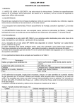
1. Technical parameters
-
Dimensions
Weight
Operating position
Operating condition
- Power supply
VoIP
•
•
•
•
•
•
•
•
•
•
•
•
•
•
•
•
•
•
•
GSM
•
•
•
•
•
133 x 233 x 60 mm
850 g
various
temperature: +5°C ÷ +40° C
Humidity: 10% ÷ 80% pi 30° C
9-15V ss or 8-12Vst, 1.5 A
Ethernet – 10/100Mb with standard BaseT and 100BaseTx, connector RJ45
SIP connection: P2P or IPPBX SIP server – tested with Cisco Call Manager, Alcatel OMNI PCX, Asterisk,
Nexspan, Panasonic…
2 VoIP channels (2 IP addresses)
Codec audio : G711u, G711a, G726, GSM
VAD (Echo cancellation)
Protocols: IP, TCP, UDP, http, TELNET, SIP, RTP
Web server for remote management
WEB – firmware upgrade
Remote connection with DTMF dial in
connection to 2nd operators after time out (adjustable) for direct dialling in
Caller Id number (CLIP)
incoming call restriction from GSM network
outgoing call restriction to GSM network
Priority connection through either the 1st or the 2nd GSM module (LCR)
Smart Call back – automatic incoming calls routing up CLIP
Direct access – assign of IP address to GSM channels
Echo canceller – switching ON/OFF
OGM* Option module for recording DISA voice message*
PIN SIM card protection
GSM 900 (class 4 – 2 W)
GSM 1800 (class 1 – 1 W)
Antenna connector SME/SMA, 50
SIM card: 3/1,8 V
2 GSM channels
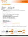
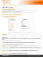
2. Setting operational Mode (P2P or SIP Server)
The Link Gate SIP can be configured in 2 different modes: P2P or SIP Server.
•
In P2P mode, the Link Gate SIP behaves as a sample GSM gateway. In case of incoming call on the GSM
module, the Link Gate SIP will convert it in SIP and transfer it to the SIP server (IPBX). For an out going call,
the Link Gate SIP process a GSM call when SIP call is receives over IP addresses.
•
In SIP Server mode, the Link Gate SIP acts as a SIP server and allow recording up to 10 IP/SIP phones. It
is also possible to register the Link Gate SIP on an existing IPBX.
P2P Mode
Linkcom France
11 rue du Soleil Levant 92140 CLAMART
SIP Server Mode
3
Copyright © 2008 – Linkcom – Tous droit réservés
In default mode, the Link Gate SIP is set in SIP server mode, to switch to P2P mode, open the unit and changes the
dipswitch position N°3 to ON.
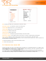
Dipswitch description:
1
2
3
4
:
:
:
:
IP default Configuration. (OFF = Default position)
not used
mode, SIP server / P2P (ON = P2P mode / OFF = SIP Server mode)
not used
3. Putting into Service
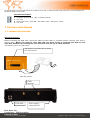
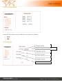
3.1. Module Description
SIM cards position :
Before inserting the SIM card, check the status of PIN code in a mobile phone (starting with PIN or
without PIN). When you want to start with PIN you have firstly to program this PIN to Link
Gate SIP. Without this setting the Link Gate SIP will not log to GSM network!
"We advise not to use PIN Code
SIM holders will release after pressing
the yellow button
SIM card position
GSM
antennas
LAN cable
Power supply –
connect at end
Back Panel Vue
Front Panel – LED description
Linkcom France
11 rue du Soleil Levant 92140 CLAMART
4
Copyright © 2008 – Linkcom – Tous droit réservés
Green LED Light: indicates that
GSM module is powered.
Red LED: indicates GSM network operation
- Flashing by 2s period = stand by status
- Fast flashing = active connection
SIM cards Status
Green LED flashing = module registered to
GSM network
Green LED fix light = Call in progress
Green LED : Indicates the
status of Incoming() and
outgoing () call via
individual IP channels
Red LED indicating channels Error status:
LED is off – stand by mode
LED blink – failure
4. Network configuration
4.1 - choosing a configuration mode and login
By default, the Link Gate SIP is configured as following:
• IP address 1 (IP proxy SIP module GSM 1) = 192.168.1.250 / 255.255.0.0
• IP address 2 (IP proxy SIP module GSM 2) = 192.168.1.251 / 255.255.0.0
• IP SIP Server (SIP Server internal)
= 192.168.1.250 / 255.255.0.0
In your web browser enter IP address of Link gate SIP, defaults setting are 192.168.1.250, user is admin, and
password is 1234.
Linkcom France
11 rue du Soleil Levant 92140 CLAMART
5
Copyright © 2008 – Linkcom – Tous droit réservés
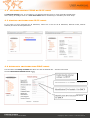
4.2 - Network settings: DHCP or IP SIP mode
In Network setting menu, It is possible to use DHCP automatic setup or enter manually IP addresses.
After making all changes click on a save and restart button. Restarting is mandatory for those steps
4.3 Manual configuration IP SIP mode:
If you prefer to enter manually the IP addresses, make sure to fill out all IP addresses, Network mask, Default
Gateway and then all DNS parameters.
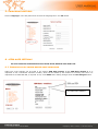
4.4 Automatic configuration DHCP mode:
Tick the Blanc box Setup via DHCP and Enter for each IP address ID1 – ID2 the Host name
And the DHCP Client ID SIP Server name
Enable/disable ethernet
settings via DHCP
Identification ID of module 1 for DHCP
Identification ID of module 1 for DHCP
Identification ID of internal SIP Server
for DHCP
Linkcom France
11 rue du Soleil Levant 92140 CLAMART
6
Copyright © 2008 – Linkcom – Tous droit réservés
5- Language option:
Select “Language” in the left panel menu choose the language then Clic Set Button.
6 – GSM gate settings
To set up Incoming and Outgoing calls trunk route, refer to menu GSM Gate
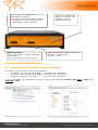
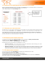
6.1 Incoming calls trunk route configuration
GSM trunk route settings can be made in the section GSM Gate module 1 and GSM Gate module 2. It is
important to set a subscriber extension number, which will be dialled by the module for incoming call. Then it is
important to set SIM card PIN, if required. If not, write 0000. After making changes click on save changes button.
SIM card PIN
Set subscrieber number
Linkcom France
11 rue du Soleil Levant 92140 CLAMART
7
Copyright © 2008 – Linkcom – Tous droit réservés
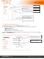
6.2 Incoming calls trunk route configuration in P2P mode
When the Link gate SIP should be set to P2P mode, it is important to set the translation table for incoming phone
calls to match phone subscriber extension’s numbers with IP addresses.
After making changes use the save changes button.
Set a number and IP
adress, whitch is set
on a desired phone.
6.3. Outgoing call configuration:
By default there is no call restriction programmed in the (LCR) table. The Link Gate SIP accepts all SIP calls through
its trunk interfaces « IP 1adress » and « IP 2adress ». Calls will be rooted sequentially over modules GSM 1 et 2.
Set up IPBX External call trunk route parameters (trunk SIP or Outbound proxy sip), SIP phone or soft phone to
make calls through the Link Gate SIP. The only parameters that should be configured are IP 1 and 2 addresses and
port SIP, 5060 (there is no SIP authentification in mode P2P).
7. SIP Server mode Configuration
To parameter the Link gate SIP in SIP server mode, refer to paragraph 2: “Setting operational mode”
In SIP Server mode « Number translation » menu is not used
Two new menus are available: « SIP Parameters » and « SIP Server »
In SIP mode Server the Link Gate SIP can be parameter in 2 ways:
•
SIP server (internal) : The Link Gate SIP work in this case in stand alone it allow recording up to 10 SIP
phone. The Link Gate SIP in this case behaves as an IPBX.
•
SIP server (external) : The Link Gate SIP is connected and registered to an IPBX as a SIP phone. For each
GSM Module one SIP account should be created on the IPBX to allow receiving external calls. Outgoing calls
through the GSM channels are made by adding 2 trunks SIP through IP 1 and IP 2 of the Link Gate SIP.
7.1. SIP server mode (internal)
Set the Link Gate SIP in MENU SIP SERVER tick the Blanc Box to Enable SIP server mode
Give then the Name of the SIP server« realm »
Enter the outgoing call prefix to access individually each channel.
You are able then to register up to 10 SIP accounts for your SIP phone.
Complete the number of each SIP phone extension ( this number will same as user SIP name in Password).
After making changes use button save and restart.
Linkcom France
11 rue du Soleil Levant 92140 CLAMART
8
Copyright © 2008 – Linkcom – Tous droit réservés
Activate/desactivate internal SIP Server
SIP Server name
Prefix for calling throught module 1 and 2
Table of enabled phones. Set a
user name and password,
whitch is set on desired phone
7.2 - SIP server mode (external)
In « SIP Server » Menu make sure that « Enable SIP server » is not Tick.
Enter then « SIP Parameters » menu and complete IPBX information to register the 2 GSM Modules :
•
•
•
•
Address : IPBX IP Address
Port : IPBX SIP Port
Name : IPBX extension SIP user name
Password : IPBX extension SIP user name password
Press then « Save changes » to save the parameters. The Link Gate SIP will inform you with a message « Failed
Saving » or « Successful Saving »
Name or IP adress of external
SIP Server for module 1
Name or IP adress of external
SIP Server for module 2
Linkcom France
11 rue du Soleil Levant 92140 CLAMART
9
Copyright © 2008 – Linkcom – Tous droit réservés
7.3 Incoming call setting:
In SIP SERVER mode Internal or External you will have to select which extension should ring during an Incoming call. fill this Extension N° in
“GSM 1 Module” and “GSM 2 Module”
7.4 Outgoing Call setting:
In SIP SERVER Mode (internal), dial the outgoing prefix number set in “SIP SERVER” Menu followed by the phone number.
In our Example GSM 1 Module prefix is 7 and GSM 2 Module prefix is 8.
In SIP SERVER Mode (External), create in the IPBX 2 Trunk SIP routes pointing on IP 1 and IP 2 of the Link Gate SIP.
8. Description of GSM Parameters
8.1 General GSM parameters
DISA: Allow callers to dial-in directly the subscriber number from 1 to 4 digits depending on the numbering schema
of the IPBX.
OGM: The Link gate SIP can be provided with OGM optional Board “DISA messages” for individual GSM channel.
Allowing recording a DISA welcoming message of 16 seconds, inviting callers to dial the subscriber’s number they
want to reach
This message can be recorded through a PC using the special supplied RS 232 interface and the recording software
OGMrec.
Rec: The new OGM module doesn't use this parameter.
Wait: when DISA is activated this Time out table allows waiting for caller to dial-in a subscriber number.
If caller do not dial in or exceed the Time out figure the call is automatically rooted to the operator.
Erase Clip: Allow erasing first Digits of the Incoming call number.
By default “0” mean no number will be delayed. You can erase the area code of an incoming call ex :
+33140831313 will be translated to 140831313.
Modules directly: By activation this feature you disabled LCR (permitted direction). The IP address 1 is
automatically assigned to SIM 1 card And IP address 2 is assigned to SIM 2 card. The LCR then can be assign
directly in the SIP server.
Echo canceller: This feature restrict ECHO during transfer between digital and analogue telephone systems.
Add zero before CLIP: Adds automatically 0 before each incoming number.
Start with module 1: The Link Gate SIP will start reading LCR in module 1.
Linkcom France
11 rue du Soleil Levant 92140 CLAMART
10
Copyright © 2008 – Linkcom – Tous droit réservés
8.2. Module GSM Parameters
PIN: Set PIN code of SIM card. If no PIN code is used enter “0000”.
Subscriber number: set Subscriber number for Incoming calls
Volume GSM: Adjust from level 1 to 7 the outgoing voice.
Volume ISDN: Adjust from 1 to 4 the Incoming voice.
Incoming calls: Enable incoming calls.
Outgoing calls: Enable outgoing calls.
Call progress tones: Warning tone giving after dialling out a phone number.
Redirection to GSM 2: In case GSM1 channel is busy allow to “overflow” to GSM2 Channel automatically.
Smart callback: Missed or refused outgoing calls are stored in Link Gate SIP with subscribed number.
When called party call back the call is automatically routed to extension which made the call. When connection was
successful data are erased from memory.
0: It adds automatically 0 before each outgoing dialled number.
Clir: Switch OFF outgoing CLIP.
8.2. Permitted Calls Menu ( LCR)
Permitted call table (LCR) allow for each GSM module to program up to 12 authorised prefixes (1 to 8 digits). If the
authorised call table is not filled all type of calls are authorised. We can assign for each of the 12 prefixes a group of
Numbers FROM xxxxxxxx To xxxxxxxx. Ex : From 0 to 9.
You can select the for each GSM Permitted table the Operator prefixes corresponding to the SIM card inserted,
Ex : GSM 1 Module (T-Mobil) GSM 2 Module (ORANGE) prefixes corresponding to T-Mobile can be inserted in GSM1
Permitted table and for Orange in GSM2 Permitted table in this way you can benefit of cheaper calls.
Linkcom France
11 rue du Soleil Levant 92140 CLAMART
11
Copyright © 2008 – Linkcom – Tous droit réservés
8.3. GSM Gateway status
The GSM Gate status provides you with all technical information’s corresponding to SIM card in GSM Module 1 and
GSM module 2.
Frequency Channel: GSM network channel number - GSM frequency connected to BTS.
Channel 0 - 124 are used for GSM 900 and channel 512 - 885 for GSM 1800.
Signal Strength, BCCH strength: GSM Signal force (Is related with Antenna position)
o
o
o
o
-113 to -99 dBm: very bad signal - it is impossible to use any GSM network services.
-98 to -83 dBm: bad signal - you can send SMS messages. Since level -87dBm you can establish voice
connection
-82 to -71 dBm: good signal - you can send SMS messages and make calls. Data transmission CSD is not
reliable
-70 to -51 dBm: very good signal - you can use all services of GSM network without any restriction.
Country Code, Network Code, Area Code: Country Code N°, Provider Network N°, where SIM card is logged
Cell ID: BTS number, where GSM module is registered.
IMSI: International Mobile Subscriber Identity
GSM Firmware version: SW version for GSM part.
Linkcom France
11 rue du Soleil Levant 92140 CLAMART
12
Copyright © 2008 – Linkcom – Tous droit réservés
8.4. Setting Audio
Choose the audio codecs priority for SIP calls. There codecs are available:
•
•
•
•
G711u
G711a
G726
GSM
8.5. Service
Firmware version
Event log (enhanced or basic log)
Download event log
Firmware upgrade
Language upgrade
Admin password change
Linkcom France
11 rue du Soleil Levant 92140 CLAMART
13
Copyright © 2008 – Linkcom – Tous droit réservés