1
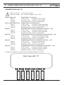
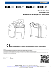
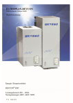
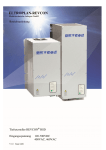
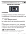
k
LANDANSCHLUSS-UMSCHALTEINHEIT LAE 111
EINBAUANLEITUNG / OWNERS MANUAL
Verwendungszweck
Die Landanschluss-Umschalteinheit LAE 111 dient zur Absicherung, Umschaltung und Überwachung
des 230V- Anschlusses (Land-Generator oder Land-Wechselrichter). 2 Netzkontroll-Leuchten zeigen
Wechselspannungsanschluss, das Voltmeter (250 V) die Bordspannung. Über die 4 zweipoligen
Schutzschalter (10 A) lassen sich die einzelnen Verbraucher schalten.
Der elektrische Anschluss erfolgt über Durchführungsklemmen, die sich an der Unterseite des Gehäuses
befinden.
Bitte beachten Sie:
Arbeiten an Anlagenteilen für Netzspannung 230V/50Hz dürfen nur durch
zugelassene Elektrofachkräfte ausgeführt werden.
Die vorliegende Montageanleitung ist Bestandteil der Komponentenlieferung. Sie muss - wichtig für
spätere Wartungsarbeiten - gut aufbewahrt und an eventuelle Folgebesitzer weitergegeben werden.
Purpose
The combined shore/generator or shore/inverter power unit LAE 111 ensures a safe and problem-free
power-supply for AC-power 230V / 50 Hz. Two power-indicationlights are showing correct power
connection either of the mains or the generator/inverter and the voltmeter (250 V) the on-board voltage.
Four consumers as water heater, battery charger, sockets and air condition can be switched by 4 double
pole thermal circuit breakers (10 A) .
The electrical connection is carried out via through lead clamps on the bottom side of the housing.
Please note that all works on plant components for shore power 230V/50 Hz must be
carried out by licensed electrical engineers.
This manual is a component of the shore power unit. It must be kept (for reference) importantly:
-for later maintenance work - and for the use of subsequent owners of the equipment.
philippi elektrische systeme gmbh
Neckaraue 19
D-71686 Remseck am Neckar
V1.4 - AUG 2013
www.philippi-online.de
[email protected]
Telefon: +49 (0)7146/ 8744-0, Fax -22
k
LANDANSCHLUSS-UMSCHALTEINHEIT LAE 111
ANSCHLUSS LAE 111
Kabelquerschnitt
Kabelquerschnitt
Netz-Zugang Land
Klemme 11
Klemme 12
Klemme PE
Netz-Zugang Bordgerät
Klemme 21
Klemme 22
Klemme PE
Ausgang A
Klemme 31
Klemme 32
Klemme PE
Ausgang B
Klemme 41
Klemme 42
Klemme PE
Ausgang C
Klemme 51
Klemme 52
Klemme PE
Ausgang D
Klemme 61
Klemme 62
Klemme PE
4 mm² für Netz-Zugang
min. 1,5 mm² für Ausgang A, B, C und D
230 Volt / 50 Hz - Netzspannung Land
L1 (Phase - schwarz) Anschluss des Landstroms
N (Nullleiter - blau) Anschluss des Landstroms
PE ( Schutzleiter - grün/gelb)
230 Volt / 50 Hz - Netzspannung Generator/Wechselrichter
L1 (Phase - schwarz) Anschluss des Generators/Wechselrichters
N (Nullleiter - blau) Anschluss des Generators/Wechselrichters
PE ( Schutzleiter - grün/gelb)
geschaltet über Überstromschutzschalter “Hot Water” - 10 A
L1 (Phase - schwarz) Anschluss des Boilers
N (Nullleiter - blau) Anschluss des Boilers
PE ( Schutzleiter - grün/gelb)
geschaltet über Überstromschutzschalter “Battery Charger” - 10 A
L1 (Phase - schwarz) Anschluss des Ladegerätes
N (Nullleiter - blau) Anschluss des Ladegerätes
PE ( Schutzleiter - grün/gelb)
geschaltet über Überstromschutzschalter “Sockets” - 10 A
L1 (Phase - schwarz) Anschluss der Steckdosen
N (Nullleiter - blau) Anschluss der Steckdosen
PE ( Schutzleiter - grün/gelb)
geschaltet über Überstromschutzschalter “Air Condition” - 10 A
L1 (Phase - schwarz) Anschluss der Klimaanlage
N (Nullleiter - blau) Anschluss der Klimaanlage
PE ( Schutzleiter - grün/gelb)
alle Ausgänge sind über den Fehlerstromschutzschalter RCBo 25 A (30 mA) abgesichert.
Rückansicht LAE 111
Seite 2
Land
3 x 4 mm²
Generat./Wandler
3 x 4 mm²
min. 3 x 1,5 mm²
Hot Water
min. 3 x 1,5 mm²
Battery Charger
min. 3 x 1,5 mm²
Sockets
Air Condition
min. 3 x 1,5 mm²
PE 62 61 PE 52 51 PE 42 41 PE 32 31 PE 22 21 PE 12 11
V1.4 - AUG 2013
k
SHORE POWER SWITCH OVER UNIT LAE 111
CONNECTION LAE 111
Wire cross section
Wire cross section
Power supply mains
clamp 11
clamp 12
clamp PE
Power supply onboard unit
clamp 11
clamp 12
clamp PE
Output A
clamp 21
clamp 22
clamp PE
Output B
clamp 31
clamp 32
clamp PE
Output A
clamp 21
clamp 22
clamp PE
Output B
clamp 31
clamp 32
clamp PE
4 mm² for power supply
min. 1,5 mm² for outputs A, B, C and D
230 Volt / 50 Hz - shore power
L1 (life - black)
Connection of shore power
N (neutral - blue)
Connection of shore power
PE (protective earth conductor - green/yellow)
230 Volt / 50 Hz - generator/inverter
L1 (life - black)
Connection of generator/inverter
N (neutral - blue)
Connection of generator/inverter
PE (protective earth conductor - green/yellow)
switched through thermal circuit breaker “Hot Water” - 10 A
L1 (life - black)
Connection of the water heater
N (neutral - blue)
Connection of the water heater
PE (protective earth conductor - green/yellow)
switched through thermal circuit breaker “Battery Charger” - 10 A
L1 (life - black)
Connection of the battery charger
N (neutral - blue)
Connection of the battery charger
PE (protective earth conductor - green/yellow)
switched through thermal circuit breaker “Sockets” - 10 A
L1 (life - black)
Connection of the sockets
N (neutral - blue)
Connection of the sockets
PE (protective earth conductor - green/yellow)
switched through thermal circuit breaker “Air Condition” - 10 A
L1 (life - black)
Connection of the air condition
N (neutral - blue)
Connection of the air condition
PE (protective earth conductor - green/yellow)
all outputs are protected by a fault-current circuit breaker RCBo 25 A (30 mA)
Rear View LAE 111
V1.4 - AUG 2013
Shore
3 x 4 mm²
Generat./Inverter
3 x 4 mm²
min. 3 x 1,5 mm²
Hot Water
min. 3 x 1,5 mm²
Battery Charger
min. 3 x 1,5 mm²
Sockets
Air Condition
min. 3 x 1,5 mm²
PE 62 61 PE 52 51 PE 42 41 PE 32 31 PE 22 21 PE 12 11
Page 3
k
SHORE POWER SWITCH OVER UNIT LAE 111
TECHNISCHE DATEN / TECHNICAL DATA
LAE 111
Versorgungsspannung
Absicherung
Ausgang A & B & C & D
Abmessungen
Einbauausschnitt
230 Volt / 50 Hz Wechselspannung
RCBo 25A, 30 mA
Überstromschutzschalter 10A; RCBO 30 mA
B 260 x H 185 x T 100
B 235 x H 160 (Mindesttiefe 97 mm)
LAE 111
Supply voltage
Protection
Output A & B & C & D
Dimensions
Installation dimensions
230 Volt / 50 Hz AC-Voltage
RCBo 25A, 30 mA
Thermal circuit breaker 10 A; RCBO 30 mA
W 260 x H 185 x D 100
W 235 x H 160 (minimum depth 97 mm)
CE-KONFORMITÄTSERKLÄRUNG
Dieses Produkt erfüllt die Anforderungen der EU - Richtlinien:
2004/108/EG "Elektromagnetische Verträglichkeit"
Störfestigkeit EN 61000-6-1
Störaussendung EN 61000-6-3
2006/95/EG "Elektrische Betriebsmittel zur Verwendung innerhalb bestimmter
Spannungsgrenzen"
Die Konformität des Gerätes mit den o.g. Richtinien wird durch das CE-Kennzeichen bestätigt.
DECLARATION OF CONFORMITY
This device fulfills the requirements of the European regulations:
2004/108/EG “ElectroMagnetic Compatibilit”
Immunity
EN 61000-6-1
Emission
EN 61000-6-3
2006/95/EG “Electrical equipment designed for use within certain voltage limits”
The conformity to this regulations is certified by the CE - sign.
ENTSORGUNGSHINWEISE / DISPOSAL NOTE
Beachten Sie bei der Entsorgung dieses Gerätes die geltenden örtlichen Vorschriften und
nutzen Sie die Sammeldienste/-stellen für Elektro-/Elektronik-Altgeräte.
Please take care of your local directives on waste electrical and electronic equipment.
Please use collection points for waste electrical and electronic equipment.
Seite /Page 4
V1.4 - AUG 2013