1
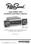
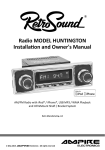
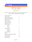
[ Ins t all at io n& O w n er s - M anual ]
M O D E L
LOC200
Contents
Introduction................................................................... 5
Installation into the vehicle......................................... 7
• LOC200 installation into the vehicle................................. 7
CAR SECURITY I CAR AUDIO I CAR MEDIA
Installation example................................................... 10
• GPS locator installation into the vehicle........................ 10
• Connection of external car alarm................................... 11
Configuration.............................................................. 13
• Entering of authorized phone numbers for
alarm SMS and controlling of „GPS higher
level protection“ mode................................................... 13
• Switch relay configuration at alarm activation.............. 15
• STOP function (relay switching)...................................... 16
• Setting of time period for sending a current
position information at GPS alarm activation................ 17
• Configuration of SMS text sent at GPS alarm
activation.......................................................................... 18
• Configuration of SMS text sent at INPUT
alarm activation............................................................... 19
• Setting of alert call in case of alarm activation............. 20
• Way of sending GPS coordinates in SMS’s...................... 21
• Setting of confirmation message for
SMS commands................................................................ 22
• Reset – renewal of factory default setting..................... 23
• Configuration identification........................................... 24
© May 2015 ampire Electronics - All rights reserved
3
User’s functions........................................................... 25
• Thief protection............................................................... 25
• GPS protection......................................................... 25
• GPS higher level protection (GPSS)......................... 28
• INPUT protection...................................................... 29
• Position SMS request....................................................... 30
• Relay switching for unlimited time................................. 32
• Relay switching for preset time...................................... 32
• Relay switching for time preset by
command RELAY.............................................................. 33
• Request for remaining credit in pay as you
go SIM card used in the LOC200..................................... 33
• Setting the LOC200 in STAND BY mode......................... 34
Finding a vehicle position...........................................36
• Finding a vehicle position on server
SATMAPS.NET................................................................... 36
Troubleshooting...........................................................37
Introduction
Dear customer,
thank you for purchasing our product. It is a modern and
technologically advanced LOC200. This product will help
you to secure and protect your vehicle (car, truck, motorcycle, caravan, construction machine, agricultural machine,
motorboat etc.). In case the guarded vehicle is stolen the
LOC200 will send you a current position to your mobile
phone. Via mobile phone you can easily view the current
map with vehicle position on the display. This service of a
displaying on a map is completely free of charge. You can
also view the position of a guarded vehicle via PC and website http://www.satmaps.net free of charge.
The system consists of a LOC200 unit and a satellite GPS antenna. The LOC200 unit is usually placed in a hidden and a
difficult to approach place (e.g. under a car dashboard). SIM
card of the GSM mobile operator is placed inside the LOC200
unit (the LOC200 has its own telephone number).
Technical Data...............................................................39
It is possible to use a contract or a pay as you go SIM cards.
In case you decide to use a pay as you go SIM card, you can
check its remaining credit using your mobile phone. Charging of the pay as you go SIM card can be done from your
mobile phone or for example using ATM (check possible options for a remote pay as you go SIM card charging with
your GSM operator).
The system will communicate with you using SMS’s, therefore
it is essential to pay attention to rates for SMS services while
choosing your mobile operator. We recommend you to acti-
4
© May 2015 ampire Electronics - All rights reserved
© May 2015 ampire Electronics - All rights reserved
5
vate roaming on the SIM card just in case of localization of
the vehicle abroad. The LOC200 unit connects to a vehicle
onboard power 12V DC. We recommend you to connect the
unit to a backup battery just in case the main power source is
stolen or inactivated. The LOC200 allows other functions,
which are described in details in this user’s manual.
Installation
LOC200 installation into the vehicle
Pin 1
Brown
Pin 2
Pin 3
Pin 4
Pin 5
Pin 6
Pin 10
Pin 11
Pin 12
Green
Blue
White
Yellow
Orange
2x black
Red
Red-white
Switching relay – common contact
(COM)
Switching relay – opening contact (NO)
Switching relay – closing contact (NC)
External alarm input (A0)
Input – ignition
External alarm input (A1)
Frame (-), - 12V backup power source
+ 12V
+ 12V backup power source
The LOC200 is intended either for separate connection or as
an addition to a car alarm.
1. Push the releasing button and slide out the SIM card holder.
Insert the SIM card in the holder and slide back in the
LOC200 together with the SIM card.
6
© May 2015 ampire Electronics - All rights reserved
© May 2015 ampire Electronics - All rights reserved
7
Note!
Note!
At first the SIM card needs to have PIN code protection deactivated. The PIN code protection can be deactivated for example in a mobile phone.
The LOC200 allows connection of backup battery to the
cable connector wires (black and red-white wire). Charging of the backup battery is done automatically while
driving. We recommend to use gel battery 12V/1,3Ah. The
battery endurance is 30 to 60 hours depending on momentary operating mode of the LOC200.
2. Connect particular wires from cable as seen on the right.
The cable connector must be disconnected from the LOC200
during wire connecting process.
Red LED – indicates GSM
Yellow, red and black wires must be always connected. Connection
of remaining wires is optional. In case particular wires are not connected relevant functions of the system will not be active.
The output of external alarm can be connected to input of
the LOC200 using white or orange cable.
• A0 (white cable) - INPUT alarm is activated by signal 0V
• A1 (orange cable) - INPUT alarm is activated by signal +12V
The maximum current carrying capacity of the switching
relay is 12V DC/5A. While controlling an appliance with a
higher current load use an auxiliary relay with appropriate
technical parameters.
3. Connect the GPS antenna and the cable connector to the
unit. GPS antenna must be placed horizontally and must not
be obstructed from the top by metal parts.
LED blinking quickly
(1x per second)
The device is connecting to GSM network
LED blinking slowly
(1x per 3 seconds)
The device is connected to GSM network
LED is not blinking
The device is switched OFF
Green LED – indicates GPS
LED blinking quickly
(1x per second)
The device is trying to receive GPS data
LED blinking slowly
(1x per 3 seconds)
The device receives actual GPS data
LED is not blinking
GPS module is switched OFF
4. Switch car ignition ON and OFF. The unit is ON now. Wait
approximately 2 minutes for the unit initialization completion. The unit is ready to receive configuration SMS
commands after that time.
8
© May 2015 ampire Electronics - All rights reserved
© May 2015 ampire Electronics - All rights reserved
9
YELLOW
Installation example
GPS locator installation into the vehicle
EXTERNAL
CAR ALARM
INPUT A1 (+12V)
ORANGE
OR INPUT A0 (0V)
WHITE
+12V
It is recommended to place the
GPS locator for example under
the dashboard. Remove the necessary covers of the dash-board
and choose a suitable place for
GPS locator and backup battery.
GPS
LOCATOR
BROWN
BLUE
NC
COM
GREEN
NO
+12V
GND
RED
BLACK
RED-WHITE
Basic connection of GPS locator
can be done via three wires (red,
black and yellow). During the
wires connection the cable connector must be disconnected from
the GPS locator!
• Red wire connect to +12V power
supply. Power supply must be continuous and must not be interrupted
even if the vehicle is parked!
• Black wire connect to a car frame
(-).
• Yellow wire connect to contact 15
(circuit which is powered +12V
when the ignition is ON).
Connection of external car alarm
The output of external alarm can be connected to input of
the GPS locator using white or orange cable.
Pin 1 Braun
Pin 2 Grün
Pin 3 Blau
Pin 4 Weiß
Pin 5 Gelb
Pin 6 Orange
Pin 10 2x Schwarz
Pin 11 Rot
Pin 12 Rot-Weiß
Relais– gemeinsamer Kontact (COM) 30
Relais – normal offen (NO) 87
Relais – normal geschlossen (NC) 87a
Externer Alarm Eingang (A0) Masse
Eingang – Zündung
Externer Alarm Eingang (A1) +12Volt
Masse
+ 12V Dauerplus
+12V Backup-Batterie
• A0 (white cable) - INPUT alarm is activated by signal 0V,
which must be longer than 0,8s
• A1 (orange cable) - INPUT alarm is activated by signal +12V,
which must be longer than 0,8s
Connect the backup battery (gel battery 12V/1,3Ah) to black
(-) and red-white (+) cable fitted with faston connector.
Beware of the polarity of battery contact!
Connection of other wires from
the cable harness is optional!
10
© May 2015 ampire Electronics - All rights reserved
© May 2015 ampire Electronics - All rights reserved
11
Schema GPS locator connection into the the vehicle with
onboard power 24V:
INPUT IGNITION
YELLOW
REPLAY
CONVERTOR
24/12V
GPS
LOCATOR
RED
BLACK
24V
CAR
Configuration
The LOC200 configuration is performed using instructions sent
as an SMS from your mobile phone to the phone number of the
LOC200. Command is always sent together with PIN code which
defines authorized user(s). The PIN code is a fourdigit number
which can be changed. The PIN code is set by manufacturer to
value 4321 (symbols **** are used instead of PIN code in the
text below). The commands can be typed both in regular or
capital letters. In case the command is not sent in a correct form,
the LOC200 will send SMS with the text COMMAND ERROR. In
case the command is sent with incorrectly entered parameters,
the LOC200 will send SMS with the text key word ERROR.
Entering of authorized phone numbers for
alarm SMS and controlling of „GPS higher
level protection“ mode
Command format: **** PHONE +aaaz +bbbz +cccz
+aaa – first authorized number in international format
+bbb – second authorized number in international format
+ccc – third authorized number in international format
z–
12
© May 2015 ampire Electronics - All rights reserved
determines whether alarm SMS to this phone
number will be sent during INPUT alarm or GPS
alarm
z = I – INPUT alarm SMS will be sent to this number only
z = G – GPS alarm SMS will be sent to this number only
© May 2015 ampire Electronics - All rights reserved
13
Switch relay configuration at alarm activation
Command format: **** RELAY xy z
4321 PHONE +42077720
0333 +420602666888G
Parameter z is optional. If this phone number is entered
without this parameter, it means that SMS‘s will be sent to
this phone number from both INPUT alarm and GPS alarm
(the value IG is set automatically).
Up to 3 telephone numbers can be as signed. All entered
(authorized) numbers can control GPS higher level protection mode by ringing the LOC200 number (see below). The
telephone numbers must be entered in international format, so the number must always begin with the symbol +.
time for which the relay stays switched (0 to 240)
y–
time unit of the number entered by parameter x
y = s – seconds
y = m – minutes
z–
determines under what circumstances the relay will
be switched
z = I – relay will be switched when INPUT alarm is
activated
z = G – relay will be switched when GPS alarm is activated
z = IG – relay will be switched when both INPUT
and GPS alarm are activated
Default setting: 1s IG
Note!
Authorized telephone numbers must have identification
of calling number CLIP activated. In case this function is
not active, function of GPS higher level protection cannot
be controlled and it is not possible to control the LOC200
by ringing.
The first authorized number set by command PHONE is
called in case of INPUT alarm or GPS alarm activation. Condition for calling the first authorized number is activation of
this function by a command CALL.
14
x–
© May 2015 ampire Electronics - All rights reserved
4321 RELAY xy z
Parameter z is optional. If the command RELAY is entered without paramter z the relay will be switched in both INPUT alarm
and GPS alarm activation (the value IG is set automatically).
This command sets the time for which the relay will be
© May 2015 ampire Electronics - All rights reserved
15
switched at alarm activation or while sending the command
SWITCH without parameter.
STOP function (relay switching)
Setting of time period for sending a current
position information at GPS alarm activation
Command format: **** PERIOD xy Nz
x–
determines whether next alarm SMS will be sent
after a certain time or distance covered
x = D – (Distance) after distance covered (Km)
x = T – (Time) after a certain time (minutes)
y–
determines the number of kilometers or minutes
(y = 1 to 60)
z–
determines the number of alarm SMS within one
activated GPS alarm (z = 1 to 30). This parameter
is optional and will be automatically set to value
N10 in case the parameter was not entered.
Command format: **** STOP n
n = 1 switches the relay for 240 minutes after the
vehicle has stopped
n = 0 immediately sets the relay to a normal contact position
4321 STOP 1
Example: Switch the relay for 240
minutes after the vehicle
has stopped.
Default setting: T5 N10
Command STOP 1 switches the relay in GPS locator for 240
minutes if speed of the vehicle is 0 Km/h. In case of sending
command while current speed of the vehicle is higher than 0
Km/h the relay will switch after the vehicle has stopped. After
the command execution (relay switch) the unit sends SMS
with exact location where the relay switched.
4321 PERIOD D4 N5
Note!
By sending command STOP 1 repeatedly the relay switched
time can be extended. Device ETLOC-30 is not an immobilization device and mustn’t be used to immobilize a vehicle.
16
© May 2015 ampire Electronics - All rights reserved
First alarm SMS is sent immediately after GPS alarm activation and next alarm SMS’s are sent every time after either
set distance in kilometers is covered or set time in minutes.
Number of sent alarm SMS’s within one activated GPS alarm
© May 2015 ampire Electronics - All rights reserved
17
is determined by parameter Nz. The GPS alarm is automatically deactivated when all SMS‘s are sent. However, the set
mode of protection is still active. If the vehicle keeps moving, new GPS alarm is activated.
Configuration of SMS text sent at GPS alarm
activation
Configuration of SMS text sent at INPUT
alarm activation
Command format: **** ITEXT xxxxx
xxxxx – your text of the message (max. 74 symbols)
Default setting: Alarm! Your car was attacked.
Command format: **** GTEXT xxxxx
xxxxx – your text of the message (max. 74 symbols)
Default setting: Alarm! Position and speed of your car:
4321 ITEXT Car alarm is
activated!
The SMS with ITEXT will be sent to a preset telephone numbers after INPUT alarm is activated. In case the ITEXT ends
with symbol „:“, the GPS data will follow after the ITEXT in
the alarm SMS.
4321 GTEXT They are
stealing your car:
The SMS with GTEXT will be sent to a preset telephone numbers after GPS alarm activation. The GPS data will follow
after this text in the alarm SMS.
Configuration of SMS text sent as a response
to a position request
Command format: **** PTEXT xxxxx
xxxxx – your text of the message (max. 74 symbols)
Default setting: Position and speed of your car:
18
© May 2015 ampire Electronics - All rights reserved
© May 2015 ampire Electronics - All rights reserved
19
alert call is only warning the user about activated alarm. We
recommend not to accept the call, the locator does not dispose of any voice functions.
4321 PTEXT Your car is
right here:
Way of sending GPS coordinates in SMS‘s
Command format: **** LINK x
The SMS with PTEXT is sent as a response to a vehicle position request (see below for the command POSITION) to the
telephone number used for sending the request. This text
will be in SMS always followed by GPS data.
Setting of alert call in case of alarm activation
x=
x=
0 – sending GPS coordinates in the text form
1 – sending GPS coordinates in the form of a link,
which shows the vehicle position on the internet
Default setting: 0
Command format: **** CALL x
x=
0 – call function is OFF
x=
1 – call function is ON
4321 LINK 1
Default setting: 0
If this function is ON, the LOC200 sends a message with GPS
coordinates in form with a link. Now the user can just click
on the link contained in SMS and view the position of the
vehicle on internet maps.
4321 CALL 1
If the function is ON, the first set authorized telephone
number is automatically called after alarm activation. This
20
© May 2015 ampire Electronics - All rights reserved
© May 2015 ampire Electronics - All rights reserved
21
Reset – renewal of factory default setting
Note!
If you want to use this function your mobile phone must be
connected to the internet and must support the web browser function. The service of displaying a vehicle position on
the map is completely free of charge.
Setting of confirmation message for
SMS commands
Command format: **** CONFIRM x
x=
x=
0 – confirmation messages OFF
1 – confirmation messages ON
Default setting: 1
Command format: **** RESET
4321 RESET
The function resets all parameters to factory default setting.
After the command is sent, initialization of the LOC200 will be
done and it is necessary to wait at least 2 minutes before the
LOC200 is ready to process next commands.
This function does not affect assigned PIN code.
4321 CONFIRM 1
If the confirmation message function is ON, after successful
command processing, the LOC200 sends SMS with the text
command OK to the telephone number sending original
command. The confirmation SMS is not sent at the commands where there is a different SMS response.
22
© May 2015 ampire Electronics - All rights reserved
© May 2015 ampire Electronics - All rights reserved
23
Configuration identification
User's function
Command format: **** CONFIG
The LOC200 sends SMS with current configuration as a response to CONFIG command.
Authorized number – INPUT
and GPS alarm are sent (IG)
Authorized number – GPS alarm
is sent (G)
Authorized number – INPUT
alarm is sent (I)
Relay configuration
Setting of period for sending
SMS’s at GPS alarm
Thief protection
Setting of confirmation for processed SMS‘s – 1 is ON GPS
Call in case of alarm activation
– 1 is ON
Sending coordinates in the form
of a link – 1 is ON
Current relay mode – 0 relay is
unswitched
Mode of GPS protection – 0 is
OFF
Mode of GPS higher level protection – 1 is ON
24
User’s functions of the LOC200 are controlled by commands
sent as an SMS from your mobile phone to the LOC200 telephone number. Command is always sent together with PIN
code which defines authorized user(s). The PIN code is a fourdigit number which can be changed. The PIN code is set by
manufacturer to value 4321 (symbols **** are used instead
of PIN code in the text below).
The commands can be typed both in regular or capital letters.
In case the command is not sent in a correct form, the LOC200
will send SMS with the text COMMAND ERROR. In case the
command is sent with incorrectly entered parameters, the
LOC200 will send SMS with the text key word ERROR.
© May 2015 ampire Electronics - All rights reserved
The LOC200 can be used for protection either separately or
together with external alarm. Modes "GPS" protection" and
"GPS higher level protection" can be used if the LOC200 is
used without car alarm. Mode "INPUT protection" can be
used in addition to the two above mentioned modes if external car alarm is connected to the LOC200.
GPS protection
The GPS protection activates alarm if the vehicle starts moving while the car ignition is OFF. This is protection against
towing the car away. We recommend to keep this kind of
protection permanently ON. This protection does not need
© May 2015 ampire Electronics - All rights reserved
25
to be deactivated before driving. The GPS protection sets
itself automatically OFF for the time of driving after car ignition is set ON.
4321 GPS 1
• Activation of protection: The GPS protection is activated using command **** GPS 1. If the protection is activated, the
car will be automatically protected every time after ignition is
set OFF.
Default setting: 1
• GPS alarm activation: GPS alarm is activated when the vehicle starts moving while car igntion is OFF (e.g. towing).
• Reaction to alarm: Alarm SMS’s with a car position data are
being sent during the whole alarm duration. The total number of alarm SMS’s depends on a momentary configuration
(see configuration command PERIOD). The activated GPS
alarm can be deactivated by ringing the telephone number
of LOC200 from authorized telephone number (alarm deactivation is confirmed by immediate rejection of the call by
LOC200). Function of GPS protection stays active until deactivated by command **** GPS 0.
Default text setting (change is
possible by command GTEXT)
GPS coordinates
• Deactivation of protection: The GPS protection can be deactivated using command **** GPS 0. There is no need to deactivate protection using any command before every single driving, since protection is deactivated automatically after car
ignition is set ON.
Speed of the vehicle
Date
GMT and time correction (see
the note below)
Alarm! Position and
speed of your car:
50d11.2842N
015d49.7743E
20km/h
10.09.10
10:02:04GMT +02:00h
4321 GPS 0
26
© May 2015 ampire Electronics - All rights reserved
© May 2015 ampire Electronics - All rights reserved
27
Note!
The LOC200 shows GMT in the SMS’s. The GMT is a part of
the GPS info. Some GSM operators provide local time correction in relation to GMT. If your GSM operator supports
such service, the LOC200 adds time correction info to the
SMS (e.g. 10:02:04GMT +02:00h), if not only GMT time is
shown (e.g. 10:02:04GMT).
GPS higher level protection (GPSS)
This mode is identical with GPS protection mode, but does
not evaluate car ignition status. GPS alarm gets activated
every time when the vehicle starts moving.
• Activation of protection: GPS higher level protection is activated by ringing the LOC200 telephone number from authorized telephone number (the LOC200 rings 2x and then rejects the call). • Deactivation of protection: GPS higher level protection is also
deactivated by ringing the LOC200 from authorized telephone
number (alarm deactivation is confirmed by immediate rejection of the call by LOC200). Deactivation must be done prior to
any drive.
• GPS alarm activation: GPS alarm is activated when the vehicle starts moving.
• Reaction to alarm: Alarm SMS’s with the car position data are
being sent during the whole alarm duration. The total number
of alarm SMS’s depends on a momentary configuration (see
28
© May 2015 ampire Electronics - All rights reserved
configuration command PERIOD). The activated GPS alarm can
be deactivated by ringing the telephone number of LOC200
from authorized telephone number (alarm deactivation is confirmed by immediate rejection of the call by LOC200). By ringing you also deactivate the mode of GPS protection.
Alarm! Position and
speed of your car:
50d11.2842N
015d49.7743E
20km/h
10.09.10
10:02:04GMT +02:00h
INPUT protection
To be able to utilize INPUT protection mode it is necessary to
have ex-ternal car alarm installed which output is connected to
input contact of the LOC200. INPUT protection sends SMS to
authorized telephone number in case that the condition for
INPUT alarm activation on input contact of the LOC200 is met.
Note!
We recommend to have the external alarm connection
done by a professional service.
• Activation of protection: INPUT protection is permanently
© May 2015 ampire Electronics - All rights reserved
29
active (considering proper installation and connection of external car alarm with the LOC200 was done).
• Deactivation of protection: INPUT protection can be deactivated by disconnecting external alarm from input contact of
the LOC200.
• INPUT alarm activation: INPUT alarm is activated when external car alarm gets activated. In case the GPS alarm was
already activated, the INPUT alarm will not be activated
(protection against cyclic communication with external car
alarm).
• Reaction to alarm: One alarm SMS informing about car attact is sent after INPUT alarm is activated. Such SMS may
contain also information about a position of a car.
Note!
The user can send the command POSITION request independently on the state of protections and on the state of
activated alarms.
In case of setting the function LINK to value 1 (function is
switched ON), the LOC200 sends SMS with GPS coordinates
in the form of a link to display the vehicle position on the
internet.
Default text setting (change is
possible by command PTEXT)
Alarm! Your car was
attacked.
GPS coordinates (displaying
coordinates in the text form)
Position SMS request
Command format: **** POSITION
The LOC200 responds to POSITION command with one SMS
30
containing GPS data. The time in which the device responds,
depends on the fact if the GPS module is momentarily switched
ON (at least one GPS protection is ON or the car engine is ON)
and it can also depend on the strength of GPS signal reception.
In case the locator does not manage to detect valid GPS data
within 5 minutes after receiving the request, the device sends
SMS with last known data marked as *OLD* (in case this position was detected after the device is switched ON).
© May 2015 ampire Electronics - All rights reserved
Speed of the vehicle
Date
GMT and time correction
© May 2015 ampire Electronics - All rights reserved
Position and speed
of your car:
50d11.2842N
015d49.7743E
0km/h
10.09.10
10:02:04GMT +02:00h
31
y = s – seconds
y = m – minutes
Position and speed
of your car:
http://satmap.net/?q=
50d12.5759N+015d04
8.9452E
0km/h
10.09.10
10:08:02GMT +02:00h
The relay in the LOC200 can be switched using command
SWITCH with parameter xy, so that particular devices can be
remotely switched ON or OFF for limited time.
Relay switching for time preset by command RELAY
Command format: **** SWITCH
GPS coordinates (displaying coordinates in the form of a link)
Relay switching for unlimited time
Command format: **** SWITCH n
n=
0 – unswitched relay
n=
1 – switched relay
In case you enter command SWITCH without any para-meters,
the data preset by command RELAY are automatically accepted.
Request for remaining credit in pay as you
go SIM card used in the LOC200
Command format: **** CREDIT xxxxx
The relay in the LOC200 can be switched using command SWITCH
with parameter n, so that particular devices in the vehicle can be
remotely switched ON or OFF for unlimited time (e.g. alarm sound).
xxxxx – dialed number for info about remaining credit in
the pay as you go SIM card. Contact your GSM
operator for the information.
Relay switching for preset time
Command format: **** SWITCH xy
x–
y–
32
time for which the relay stays switched (from 0 to 240)
time unit of the number entered by parameter x
© May 2015 ampire Electronics - All rights reserved
4321 CREDIT *100#
© May 2015 ampire Electronics - All rights reserved
33
The system will respond by message from your operator
containing info about current credit in the SIM card. This
function is applicable only if a pay as you go card is used.
Setting the LOC200 in STAND BY mode
Command format: **** OFF
In STAND BY mode the LOC200 does not respond to SMS
commands and ringing. The LOC200 can be “woken up”
from this mode by either switching car ignition ON or by
signal on external input (external alarm activation). Under
such conditions the protection mode set before STAND BY
mode activation remains active. The only limitation will be
during protection against car towing away (without either
alarm activation or switching ignition ON).
In STAND BY mode the LOC200 is switched OFF and its power consumption is 0 mA. STAND BY mode is recommended
to be used for long time car parking (e.g. in winter time).
Mode
Description
Power consumption
Ready
The device is ON
and responds to all
SMS commands. GPS
protection and GPS
higher level protection are OFF.
Max. 20mA*
Recommended maximum time for not
using (driving) the car
is 6 weeks.
GPS
protection
The device is ON and
responds to all SMS
commands. At least
one GPS protection
is ON.
Max. 40mA*
Recommended maximum time for not
using (driving) the car
is 2 weeks.
Standby
The device is OFF and
does not respond to
any SMS commands.
0mA
Empfohlen bei sehr
langer Parkzeit.
The power consumption will be temporarily increased by
20mA when the relay is in the switched mode.
34
© May 2015 ampire Electronics - All rights reserved
© May 2015 ampire Electronics - All rights reserved
35
Finding a vehicle position
Troubleshooting
Finding a vehicle position on server SATMAPS.NET
Problem
Solution
The device does
not switch ON
Check the connection of power supply wires
and wire “input – ignition“ and switch car
ignition ON.
The device does not
log in GSM network
– red LED is blinking in interval
1x per second
Check whether the SIM card is properly
inserted. Check availability of GSM operator
signal. Check whether inserted SIM card has
disabled PIN code protection.
After successful logging the red LED must
blink in interval 1x per 3 seconds
The device does
not respond to SMS
commands
Check whether the device is switched ON and
logged in GSM network. The logging in the
GSM can be also verified by ringing the device.
Make sure that commands are entered in
correct format with valid PIN code.
In case you use a pay as you go SIM card, make
sure that the SIM is still active and that there is
enough credit for sending SMS‘s.
After the device is switched ON it is necessary
to wait for device initialization completion (it
can last up to 2 minutes) before first command
can be sent.
Previous SMS command must be processed
before next SMS command can be sent.
The device responds
to SMS commands,
but does not
respond to ringing
from authorized
telephone number
Check the validity of entered authorized telephone number (including a country code) by
using command CONFIG.
Verify whether the authorized telephone number has CLIP service activated (identification of
a calling
number).
1. Enter internet address www.satmaps.net to your internet browser.
2. Type the GPS coordinates received by SMS in Latitude and
Longitude fields.
3. Click the button „Show position“ and wait for showing the
position of your vehicle on a map
Position and speed
of your car:
45d36.1935N
009d27.9519E
0km/h
10.09.10
10:08:02GMT +02:00h
36
© May 2015 ampire Electronics - All rights reserved
© May 2015 ampire Electronics - All rights reserved
37
Problem
Solution
The device does
not activate GPS
alarm
Check whether appropriate GPS protection
was activated (GPS 1, GPSS 1).
Check whether the GPS antenna is properly
connected and placed.
Check whether entered telephone numbers
for sending alarm SMS‘s are correct.
False GPS alarm
Check whether the GPS antenna is placed
horizontally and is not obstructed from the
top by metal parts of the vehicle.
The device dispose of a sophisticated algorithm for activation of GPS alarms. In very
rare cases an activation of false alarm may
occur which does not have to be caused by
defect of the device or wrong installation.
This situation might happen in garages and
close to high buildings where the device can
receive for longer time bad or reflected GPS
signal.
Forgotten PIN code
of the device
Please contact your dealer, the device can be set
to its default factory setting including the PIN
only by a manufacturer.
Technical Data
GSM-Modul
• Quad-Band GSM 850/900/1800/1900MHz
• Compliant to GSM phase 2/2+:
- Class 4 (2 Watt @ GSM850/900MHz)
- Class 1 (1 Watt @ GSM1800/1900MHz)
• Modern integrated GSM antenna 900/1800/1900 MHz
GPS-Modul
• Receiver 20 channels, L1 1575.42 MHz, C/A code 1,023 MHz
chip rate
• Accuracy Position 2.5 m CEP
• Chip set SiRF star III GSC3f
• Hot start < 1 s, average, open sky
• Warm start: 35 s, average, open sky
• Cold start: 35 s, average, open sky
• Support AGPS
• Low power consumption 160mW at 3.3 V (full power)
• Protocols
• NMEA-0183
• SiRF binary
• RTCM SC-104
• Crystal oscillator (TCXO), temperature compensated with
frequency stability of ±0.5 ppm
Stromversorgung / Stromverbrauch
Das Gerät
antwortet auf
SMS-Befehle, aber
nicht auf Anrufe
von autorisierten
Telefonnummern
38
Überprüfen Sie die Gültigkeit der autorisierten
Telefonnummern (einschließlich der Ländervorwahl), indem Sie den Befehl CONFIG benutzen.
Überprüfen Sie, ob die autorisierten Nummern
den CLIP Service aktiviert haben.
(Identifizierung einer Anrufnummer)
© May 2015 ampire Electronics - All rights reserved
• Vehicle onboard power (12V DC)
• Ready: The device is ON and responds to all SMS commands
(GPS protection is OFF) — max. 20mA.
• GPS protection: The device is ON and responds to all SMS
commands (at least one GPS protection is ON) — max. 40mA.
• STAND BY: The device is OFF and does not respond to any
SMS commands — 0mA.
© May 2015 ampire Electronics - All rights reserved
39
Backup battery
We recommend gel battery 12V/1,3Ah. The battery endurance is 30 to
60 hours (depending on momentary operating mode of the LOC200).
Charging of the backup battery is done automatically while driving
(yellow wire).
Functions / Construction
• Inserting the SIM card via side-drawer
(no need to open the device)
• LEDs indicating the GSM and GPS status are integrated in
the device
• The maximum current carrying capacity of the switching
relay is 12V DC/5A
• Highly improved remote control of integrated switching relay
• Possibility to control remotely particular vehicle devices via
your mobile phone (e.g. heater remote control)
• Input for external car alarm with a possibility to use GPS
locator also as GSM pager (input is activated by signal 0V or 12V)
• Function CALL at alarm activation enables automatic call to
preset telephone number – better alert in case of alarm activation
• Displaying the vehicle current position on the map directly on
your mobile phone display (this service is without any additional
fees – completely free of charge)
• Simplified searching of the vehicle position on internet via portal
satmaps.net (this service is without any additional fees –
completely free of charge)
• Possibility to edit embedded texts of alert and information SMS‘s
• LOC200 setting is done using mobile phone
• 4 digit PIN code to guarantee security
Weight / Dimensions
• 72g
• 68 x 20 x 60mm
40
© May 2015 ampire Electronics - All rights reserved
ampire
ELECTRONICS
Langwadener Straße 60
D-41516 Grevenbroich
Email: [email protected]
Technical Support:
Phone.: +49-2181-81955-0
Email: [email protected]
www.ampire.de
© 2015 AMPIRE ELECTRONICS. All rights reserved. Reprint is only permitted with a written authorization.