1
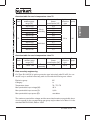
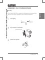
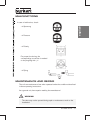
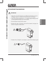
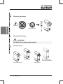
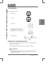
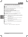
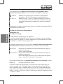
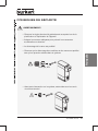
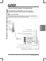
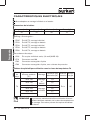
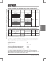
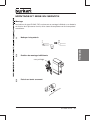
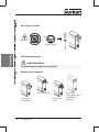
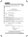
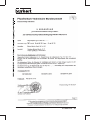
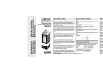
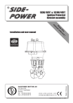
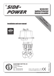
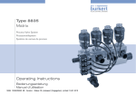
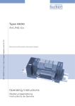
PTB 01 ATEX2173
Example/Beispiel/Exemple
Type 6104
Device with II 2G Ex i-approval
Geräte mit II 2G Ex i-Zulassung
Appareils avec mode de protection II 2G Ex i
Operating Instructions
Bedienungsanleitung
Instructions de Service
GB
ATEX Approval
Since 01.07.2003, the new EC Guideline 94/9/EC (ATEX 100a) is being applied.
The present Bürkert product complies with the requirements of this Guideline. Compared with the previous approval, only the marking has changed; the devices are
technically identical.
The markings will change
as follows:
D
new
PTB Ex-95.D.2159
PTB 01 ATEX 2173
EEx ia IIC T6
II 2 G Ex ia IIC T5 or T6
CE
CE0102
ATEX-Zulassung
Seit dem 01. 07. 2003 wird die neue EG-Richtlinie 94/9/EG (ATEX 100a) angewendet. Das vorliegende Bürkert-Produkt entspricht den Anforderungen dieser Richtlinie.
Im Vergleich zur bisherigen Zulassung hat sich nur die Kennzeichnung geändert, technisch sind die Geräte identisch.
Die Kennzeichnungen
unterscheiden sich wie folgt:
F
old
alt
neu
PTB Ex-95.D.2159
PTB 01 ATEX 2173
EEx ia IIC T6
II 2 G Ex ia IIC T5 oder T6
CE
CE0102
Homologation ATEX
Depuis le 01. 07. 2003 la nouvelle directive CE 94/9/CE (ATEX 100a) est appliquée.
Le présent produit Bürkert correspond aux exigences de cette directive. Comparé à
l‘homologation existante jusqu‘à maintenant, seul le marquage a changé, les appareils
sont techniquement identiques. Les identification se
différencient comme suit:
ancien
nouveau
PTB Ex-95.D.2159
PTB 01 ATEX 2173
EEx ia IIC T6
II 2 G Ex ia IIC T5 ou T6
CE
CE0102
We reserve the right to make technical changes without notice.
Technische Änderungen vorbehalten.
Sous resérve de modification techniques.
© 2002 - 2007 Bürkert Werke GmbH & Co. KG
Operating Instructions 0711/11_EU-ML_00804545
EC DECLARATION OF CONFORMITY...................................................................................... 4
Intended use.................................................................................................................................... 8
Safety notes.................................................................................................................................... 9
OPERATING CONDITIONS OF THE COILS.........................................................................10
Technical data.............................................................................................................................11
General notes on the technical data of the device...................................................11
Electrical data...........................................................................................................................12
ASSEMBLY AND COMMISSIONING.......................................................................................15
Malfunctions................................................................................................................................17
Maintenance and repair.....................................................................................................17
Annex....................................................................................................................................................51
EC Design Test Certificate ..................................................................................................52
01 ATEX 2173 - english
Devices with II 2G Ex i approval
PTB 01 ATEX 2173
EC DECLARATION OF CONFORMITY
We hereby declare that the products with the designation
english
Type 6104
satisfy the requirements which are specified in the Council Directives to approximate
the laws of the member states:
• Low Voltage Directive (LVD) (2006/95/EC)
• Electromagnetic compatibility (Directive 89/336/EWG)
• Pressure Equipment Directive (97/23/EG)
• ATEX-Directive (94/9/EC)
The following standards were used to assess the products concerning complaince
with the Low Voltage Directive (2006/95/EG):
EN 50178
Electronic equipment for use in power installations
EN 60730-1 Automatic electrical controls for household and similar use Part 1: General requirements
EN 60664-1 IInsulation coordination for equipment within low-voltage systems Part 1: Principles, requirements and tests
EN 60204-1 Safety of machinery – Electrical equipment of machines
Part 1: General requirements
EN 60529
Degrees of protection provided by enclosures (IP code).
Additional requirements for solenoid valves:
DIN VDE 0580
Electromagnetic devices and components General specifications.
- 01 ATEX 2173
The following standards were used to assess the products concerning the
Directive on Electromagnetic Compatibility (89/336/EEC):
EN 61000-3-2 Electromagnetic compatibility (EMC)
Part 3-2: Limits - Limits for harmonic current emissions
(equipment input current <= 16 A per phase)
EN 61000-3-3 Electromagnetic compatibility (EMC)
Part 3-3: Limits - Limitation of voltage changes, voltage fluctuations and flicker in public low-voltage supply systems, for equipment with rated current <=16 A per phase and not subject to
conditional connection.
EN 61000-6-2 Electromagnetic compatibility (EMC)
Part 6-2: Generic standards - Immunity for industrial environments
EN 61000-6-4 Electromagnetic compatibility (EMC)
Part 6-4: Generic standards - Emission standard for industrial
environments.
For the assessment of the products according to the ATEX directive (94/9/EC)
one or several of the following standards were used. The used standards are listed
in the EC Type Examination Certificate.
EN 60079-0
Electrical apparatus for explosive gas atmospheres
Part 0: General requirements
EN 60079-1
Electrical apparatus for explosive gas atmospheres
Part 1: Flameproof enclosures „d“
EN 60079-7
Explosive atmospheres
Part 7: Equipment protection by increased safety „e“
EN 60079-11
Explosive atmospheres
Part 11: Equipment protection by intrinsic safety „i“
EN 60079-15
Electrical apparatus for explosive gas atmospheres
Part 15: Construction,test and marking of type of protection „n“
electrical apparatus
EN 60079-18
Electrical apparatus for explosive gas atmospheres
Part 18: Construction, test and marking of type of protection
encapsulation „m“ electrical apparatus
EN 61241-0
Electrical apparatus for use in the presence of combustible dust
Part 0: General requirements
EN 61241-1
Electrical apparatus for use in the presence of combustible dust
Part 1: Protection by enclosures „tD“.
01 ATEX 2173 - english
english
The following standards were also used to assess non-electrical equipment and
equipment in the filling station area:
EN 13463-1
Non-electrical equipment for potentially explosive atmospheres
Part 1: Basic method and requirements
EN 13617-1
Petrol filling stations
Part 1: Safety requirements for construction and performance of
metering pumps, dispensers and remote pumping units.
The production of electrical equipment, for which an EC-type examination certificate
is available, is monitored by;
Physikalisch Technischen Bundesanstalt
Bundesallee 100
38116 Braunschweig
Such units are labeled with CE0102.
The EC-type examination certificate comes with the operations manual, where the
number can also be found. As a general rule, the standards found in the EC-type
examination certificate are valid.
The following standards have been used to assess the products with respect to
Pressure Equipment Directive (97/23/EG):
EN 60730-1
Automatic electrical controls for household and similar use
Part 1: General requirements
EN 60730-2-8
Automatic electrical controls for household and similar use
Part 2-8: Particular requirements for electrically operated water
valves, including mechanical requirements.
The products have been subjected to the following conformity assessment
procedure:
Modules A
Internal production control.
The Pressure Equipment Directive for products with a nominal voltage < 50V is
applied to the CE mark only for equipment which has a nominal width > 25 mm
and controls gases belonging to Group 1 or vapour or controls gases belonging to
Group 2 and the product is within the range > 1,500 and < 3,500 for the calculation nominal pressure x nominal width > 1,500 and < 3,500.
- 01 ATEX 2173
The manufacturer is responsible for this declaration which was prepared on
29. 10. 2007 by the
for
Undersigned:
Sonja Drolshagen, Certifications Engineer
Manufacturer:
Bürkert Werke GmbH & Co.KG
Address:
Christian-Bürkert-Straße 13-17
City:
74653 Ingelfingen
01 ATEX 2173 - english
The products with a nominal voltage >= 50V with respect to Pressure Equipment
Directive (97/23/EC) are assessed in Article 1 Paragraph 3.6 of this directive, according to which the equipment is measured by the Low Voltage Directive and
therefore does not drop below the scope of the Pressure Equipment Directive.
Intended use
english
Please observe the notes in these operating instructions as well as the
conditions of use and permitted data specified on the data sheet of the device in use, in order that the device will function perfectly and have a long
service life.
• On non-observance of these notes and unauthorized interference with the
device, we will refuse all liability and the guarantee on device and accessories will become void!
• The device serves exclusively as a solenoid valve for the media stated in
the data sheet and for use in Explosion Group II, Category 2 G and
-approval plate).
Temperature Class T4, T5 or T6 (see data on the
• The type of protection used is inherent safety Ex i for coils with circular
connectors, rectangular connectors with and without protective collars as
well as connection via single impressed wires.
• Any other use or use exceeding the specific scope is considered to be
non-intended use. Bürkert will not be liable for any damage resulting therefrom. The risk will be borne by the user.
- 01 ATEX 2173
Warning!
• Keep to generally recognized technical safety rules in planning the use of
and operating the device.
• Take suitable precautions to prevent inadvertent operation or damage by
unauthorized action.
• The valve may not be disassembled!
• Note that in systems under pressure, piping and valves may not be
loosened.
0 bar, psi, kPa
• Before interfering with the system, always switch off the voltage!
01 ATEX 2173 - english
Safety notes
OPERATING CONDITIONS OF THE COILS
english
1. Individual assembly / Block assembly
The solenoids Type G1 642735 are suitable for individual and block assembly
(see „Electrical data“).
2. Operating temperature range
Observe the operating temperature range for each type given in „Electrical data“!
10 - 01 ATEX 2173
Technical data
Warning!
XXXXXXX
PTB 01 ATEX 2173
II 2 G Ex ia IIC T6
IEC Ex PTB 06.0101
Ex ia IIC T6 6104
P, U, I see manual
S/N XXXXX CE0102
W2YLT
The technical data given on the rating plate of each device shall not be
exceeded!
M
Ex designation
IEC Ex certification No.
Ex designation
Mode of protection/temperature code
Example
Made in Germany
PTB certification No.
PTB 01 ATEX 2173
II 2 G Ex ia IIC T6
IEC Ex PTB 06.0101
Ex ia IIC T6 6104
P, U, I see manual
S/N XXXXX CE0102
XXXXXXX
W2YLT
Ident. no / date of production
Serial no. of the coil /CE designation
Voltage (±10 %) - power rating
(see manual)
01 ATEX 2173 - 11
english
General notes on the technical data of the
device
ad
e
in
G er
m
an
y
Electrical data
english
Coils suitable for individual and block assembly.
Coil dimensions
Lenght (mm)
Width (mm)
Height (mm)
Mass (g)
18
10
22
10
Approval code:
PD87
Ex ia IIC T6, assembly as individual device
PD91
Ex ia IIC T6, in block assembly
PE33
Ex ia IIC T5, assembly as individual device
PE34
Ex ia IIC T5, in block assembly
PE89
Ex ia IIC T4, in block assembly
Electrical connection:
JC09
Impressed single wires 0.2 mm2 (AWG 24)
JF79
Circular connector M8
JF80
Rectangular connector 2-pole
JF82
Rectangular connector 2-pole without protective collar
Overview table for use in temperature class T6
Temp.
class
Max.permissible
ambient temp.
range [°C]
-40 to +45
-40 to +40
Max. permissible
Ignition
GasAssembly power consump- protection
group
tion [W]
type
Block
assembly
-40 to +55
T6
-40 to +50
-40 to +45
-40 to +40
NOTE
12 - 01 ATEX 2173
0,4
0,5
0,4
Individual
0,5
Ex ia
IIC
0,7
0,8
The max. permissible power consumption depends on the max.
ambient temperature, the temperature class and the type of
assembly. These values can be taken from the above table.
Overview table for use in temperature class T5
T5
Max. permissible
ambient temp.
range [°C]
-40 to +60
-40 to +55
-40 to +50
-40 to +45
-40 to +40
-40 to +70
-40 to +65
-40 to +60
-40 to +55
-40 to +50
Assembly
Block
assembly
Individual
-40 to +45
Max. permissible
power
consumption [W]
0,4
0,5
0,6
0,7
0,8
0,4
0,5
0,7
0,8
1
Ignition
protection
type
Gasgroup
Ex ia
IIC
english
Temp.
class
1,1
Overview table for use in temperature class T4
Temp.
class
Max. permissible
ambient temp.
range [°C]]
T4
-40 to +60
Assembly
Block
assembly
Max. permissible
power
consumption [W]
Ignition
Gasprotection group
type
0,9
Ex ia
IIC
Data on safety engineering
Coil Type G1 642735 in ignition protection type intrinsically safe Ex ia IIC, for connection only to certified intrinsically safe circuits with the following max. values:
Explosion group:
IIC
Category:
ia
Temperature class:
T4 / T5 / T6
Max. permissible input voltage (Ui):
35 V
Max. permissible input current (Ii):
0,9 A
Max. permissible input power (Pi):
see tables
The maximum permissible voltages and the associated maximum permissible shortcircuit currents for the corresponding gas group may be taken from Table A1 in the
standard DIN EN 50020, Edition 1994.
01 ATEX 2173 - 13
As an example, some pairs of values for the ignition protection type Ex ia are given
for the gas group IIC.
english
Coil Type G1 642 735 in ignition protection type intrinsically safe Ex ia IIC.
Voltage value [V] = Ui
Current value [A] = li
15
0.9
18
0.44
20
22
25
28
0.309 0.224 0.158 0.12
30
35
0.101 0.073
Data on technical function
Coils of Type G1 642 735 are available in 2 versions:
1) Version for use with supply modules 300 Ω (300 Ω barrier).
2) High resistance version for use with other approved supply modules (e.g. 8-fold
remote I/O from Company Stahl).
Version
Resistor
R20 [W]
Min. terminal
voltage [V]
Min. current
[mA]
Distinction
code
Versionor use with
300 W supply
module
320
9,3
29
01
510
11,7
23
02
125
6,1
49
03
High resistance
version
Version for type
8650
The maximum voltage and current values are determined by the permissible electrical equipment.
Permissible ambient temperature range
The maximum permissible ambient temperature depends on the input power, temperature class and the type of assembly. The relevant values should be taken from
the above tables.
Type of protection
At least IP 20 to EN 60529 (DIN VDE 0470 Part 1).
14 - 01 ATEX 2173
ASSEMBLY AND COMMISSIONING
Coils of Type G1 642 735 are suitable for individual and block assembly, depending on the input power, temperature class and ambient temperature.
Clean piping
Any orientation of installation
preffered direction
Attach filter upstream
on
cti
w
flo
e
dir
01 ATEX 2173 - 15
english
Assembly
english
Fluidic connection
0 bar, psi, kpa
Assembly/Disassembly
Warning!
The device may not be disassembled!
Types of connection
2 individual wires
Rectangular plug
connector
16 - 01 ATEX 2173
Circular plug
connector
Rectangular plug
connector without
protective collar
Malfunctions
In case of malfunction, check:
english
→ Spannung
→ Pressure
bar, psi, kPa
→ Polarity
For proper functioning, the
corresponding connection is marked
on the plug flag with „+“.
→ Piping
Maintenance and repair
The coils are maintenance free when operated under the conditions described
in these operating instructions.
As a general rule, have repairs made by the manufacturer!
Warning!
The valve may not be opened during repair or maintenance work on the
installation!
01 ATEX 2173 - 17
english
18 - 01 ATEX 2173
Geräte mit II 2G Ex i-Zulassung
PTB 01 ATEX 2173
EG - Konformitätserklärung.........................................................................................20
Sicherheitshinweise..............................................................................................................25
Einsatzbedingungen der Spulen...............................................................................26
Technische Daten.....................................................................................................................27
Allgemeine Hinweise zu den technischen Daten des Gerätes..........................27
Elektrische Daten....................................................................................................................28
Montage und Inbetriebnahme.......................................................................................31
Störungen.......................................................................................................................................33
Wartung und Reparatur.....................................................................................................33
Anhang................................................................................................................................................51
EG-Baumusterprüfbescheinigung ................................................................................ 57
01 ATEX 2173 - 19
deutsch
Bestimmungsgemässe Verwendung........................................................................24
EG - Konformitätserklärung
Hiermit erklären wir, dass die Erzeugnisse mit der Bezeichnung
Typ 6104
den Anforderungen entsprechen, die in den Richtlinien des Rates zur Angleichung
der Rechtsvorschriften der Mitgliedstaaten festgelegt sind:
• Niederspannungsrichtlinie (2006/95/EG)
deutsch
• Richtlinie über die elektromagnetische Verträglichkeit
(89/336/EWG)
• Druckgeräterichtlinie (97/23/EG)
• ATEX-Richtlinie (94/9/EG)
Zur Beurteilung der Erzeugnisse hinsichtlich Einhaltung der Niederspannungsrichtlinie (2006/95/EG) wurden folgende Normen herangezogen:
EN 50178
Ausrüstung von Starkstromanlagen mit elektronischen Betriebsmitteln
EN 60730-1 Automatische elektrische Regel- und Steuergeräte für den Hausgebrauch und ähnliche Anwendungen
– Teil 1: Allgemeine Anforderungen
EN 60664-1 Isolationskoordination für elektrische Betriebsmittel in
Niederspannungsanlagen
– Teil 1: Grundsätze, Anforderungen und Prüfungen
EN 60204-1 Sicherheit von Maschinen - Elektrische Ausrüstung von Maschinen
– Teil 1: Allgemeine Anforderungen
EN 60529
Schutzarten durch Gehäuse (IP-Code).
zusätzlich für Magnetventile:
DIN VDE 0580
Elektromagnetische Geräte und Komponenten - Allgemeine
Bestimmungen.
20 - 01 ATEX 2173
Zur Beurteilung der Erzeugnisse hinsichtlich der Richtlinie zur elektromagnetischen Verträglichkeit (89/336/EWG) wurden folgende
Normen herangezogen:
EN 61000-3-3 Elektromagnetische Verträglichkeit (EMV)
– Teil 3-3: Grenzwerte - Begrenzung von Spannungsänderungen,
Spannungsschwankungen und Flicker in öffentlichen Niederspannungs-Versorgungsnetzen für Geräte mit einem Bemessungsstrom <=16 A je Leiter, die keiner Sonderanschlussbedingung
unterliegen
EN 61000-6-2 Elektromagnetische Verträglichkeit (EMV)
– Teil 6-2: Fachgrundnormen - Störfestigkeit für Industriebereiche
EN 61000-6-4 Elektromagnetische Verträglichkeit (EMV)
– Teil 6-4: Fachgrundnormen; Fachgrundnorm Störaussendung
für Industriebereich.
Zur Beurteilung der Erzeugnisse hinsichtlich der ATEX - Richtlinie (94/9/EG)
wurden entsprechend der Baumusterprüfbescheinigung, eine oder mehrere der
folgenden Normen herangezogen:
EN 60079-0
Elektrische Betriebsmittel für gasexplosionsgefährdete Bereiche
– Teil 0: Allgemeine Anforderungen
EN 60079-1
Elektrische Betriebsmittel für gasexplosionsgefährdete Bereiche
– Teil 1: Druckfeste Kapselung „d“
EN 60079-7
Explosionsfähige Atmosphäre – Teil 7: Geräteschutz durch
erhöhte Sicherheit „e“
EN 60079-11
Explosionsfähige Atmosphäre – Teil 11: Geräteschutz durch
Eigensicherheit „i“
EN 60079-15
Elektrische Betriebsmittel für gasexplosionsgefährdete Bereiche
– Teil 15: Konstruktion, Prüfung und Kennzeichnung von elektrischen Betriebsmitteln der Zündschutzart „n“
EN 60079-18
Elektrische Betriebsmittel für gasexplosionsgefährdete Bereiche
– Teil 18: Konstruktion, Prüfung und Kennzeichnung elektrischer
Betriebsmittel mit der Schutzart Vergusskapselung „m“
EN 61241-0
Elektrische Betriebsmittel zur Verwendung in Bereichen mit
brennbarem Staub – Teil 0: Allgemeine Anforderungen
EN 61241-1
Elektrische Betriebsmittel zur Verwendung in Bereichen mit
brennbarem Staub – Teil 1: Schutz durch Gehäuse „tD“.
01 ATEX 2173 - 21
deutsch
EN 61000-3-2 Elektromagnetische Verträglichkeit (EMV)
– Teil 3-2: Grenzwerte - Grenzwerte für Oberschwingungsströme
(Geräte-Eingangsstrom <= 16 A je Leiter)
deutsch
Zur Beurteilung nicht-elektrischer Geräte und der Geräte im Tankstellenbereich
wurde zusätzlich folgende Norm herangezogen:
EN 13463-1
Nicht-elektrische Geräte für den Einsatz in explosionsgefährdeten Bereichen – Teil 1: Grundlagen und Anforderungen
EN 13617-1
Tankstellen – Teil 1: Sicherheitstechnische Anforderungen an
Bau- und Arbeitsweise von Zapfsäulen, druckversorgten Zapfsäulen und Fernpumpen.
Die Fertigung der elektrischen Betriebsmittel, für die eine EG Baumusterprüfbescheinigungen vorliegt, wird überwacht von der
Physikalisch Technischen Bundesanstalt
Bundesallee 100
38116 Braunschweig
Die Kennzeichnung CE0102 wird auf diese Geräte aufgebracht.
Die EG-Baumusterprüfbescheinigung liegt der Bedienungsanleitung bei, aus der
auch die Nummer entnommen werden kann.
Zur Beurteilung der Erzeugnisse hinsichtlich Druckgeräterichtlinie (97/23/EG)
wurden folgende Normen herangezogen:
EN 60730-1
Automatische elektrische Regel- und Steuergeräte für den
Hausgebrauch und ähnliche Anwendungen
– Teil 1: Allgemeine Anforderungen
EN 60730-2-8
Automatische elektrische Regel- und Steuergeräte für den
Hausgebrauch und ähnliche Anwendungen
– Teil 2-8: Besondere Anforderungen an elektrisch betriebene
Wasserventile, einschließlich mechanischer Anforderungen.
Die Erzeugnisse wurden folgenden Konformitätsbewertungsverfahren unterzogen:
Module A
Interne Fertigungskontrolle.
Die Druckgeräterichtlinie für Erzeugnisse mit Nennspannung < 50V wird für die
CE Kennzeichnung nur angewandt bei Geräten mit einer Nennweite > 25 mm,
die Gase der Gruppe 1 oder Dampf steuern oder die Gase der Gruppe 2 steuern
und das Produkt im Bereich > 1500 und < 3500 für die Berechnung Nenndruck x
Nennweite > 1500 und < 3500 liegt.
22 - 01 ATEX 2173
Zur Beurteilung der Erzeugnisse mit Nennspannung >= 50V hinsichtlich Druckgeräterichtlinie (97/23/EG) greift Artikel 1 Absatz 3.6 dieser Richtlinie, nach der die
Geräte von der Niederspannungsrichtlinie erfasst werden und somit nicht unter den
Geltungsbereich der Druckgeräterichtlinie fallen.
i. A.
Unterzeichner:
Sonja Drolshagen, Certifications Engineer
Hersteller:
Bürkert Werke GmbH & Co.KG
Adresse:
Christian-Bürkert-Straße 13-17
Ort:
74653 Ingelfingen
01 ATEX 2173 - 23
deutsch
Diese Erklärung wird verantwortlich für den Hersteller abgegeben am 29. 10. 2007
durch
Bestimmungsgemässe Verwendung
Bitte beachten Sie die Hinweise dieser Betriebsanleitung sowie die Einsatzbedingungen und zulässigen Daten gemäß Datenblatt des eingesetzten
Gerätes, damit es einwandfrei funktioniert und lange einsatzfähig bleibt.
deutsch
• Bei Nichtbeachtung dieser Hinweise sowie bei unzulässigen Eingriffen in
das Gerät entfällt jegliche Haftung unsererseits, ebenso erlischt die Garantie auf Geräte u. Zubehörteile!
• Das Gerät dient ausschließlich als Magnetventil für die laut Datenblatt
zulässigen Medien und für den Einsatz in Explosionsgruppe II, Kategorie 2
G und Temperaturklasse T4, T5 oder T6
(siehe Angaben auf dem
-Zulassungsschild).
• Die angewandte Schutzart ist die Eigensicherheit Ex i für Spulen mit Rundsteckeranschluss, Rechtecksteckeranschluss mit und ohne Schutzkragen
sowie Anschluss über eingepresste Einzellitzen.
• Eine andere oder darüber hinausgehende Benutzung gilt als nicht bestimmungsgemäß. Für hieraus resultierende Schäden haftet Bürkert
nicht. Das Risiko trägt allein der Anwender.
24 - 01 ATEX 2173
Sicherheitshinweise
Warnung!
• Treffen Sie geeignete Maßnahmen, um unbeabsichtigtes Betätigen oder
unzulässige Beeinträchtigungen auszuschließen.
• Das Ventil darf nicht demontiert werden !
• Beachten Sie, dass in Systemen, die unter Druck stehen, Leitungen und
Ventile nicht gelöst werden dürfen.
0 bar, psi, kPa
• Schalten Sie vor Eingriffen in das System in jedem Fall die Spannung ab!
01 ATEX 2173 - 25
deutsch
• Halten Sie sich bei Einsatzplanung und Betrieb des Gerätes an die einschlägigen allgemein anerkannten sicherheitstechnischen Regeln.
Einsatzbedingungen der Spulen
1. Einzelmontage / Blockmontage
Die Magnetspulen Typ G1 642735 sind für Einzel- und Blockmontage geeignet
(siehe "Elektrische Daten").
deutsch
2.Einsatztemperaturbereich
Beachten Sie für jeden Typ den bei den „Elektrischen Daten“ aufgeführten Einsatztemperaturbereich!
26 - 01 ATEX 2173
Technische Daten
Allgemeine Hinweise zu den technischen Daten
des Gerätes
Warnung!
XXXXXXX
PTB 01 ATEX 2173
II 2 G Ex ia IIC T6
IEC Ex PTB 06.0101
Ex ia IIC T6 6104
P, U, I see manual
S/N XXXXX CE0102
W2YLT
deutsch
Die auf dem Typschild des jeweiligen Gerätes angegebenen technischen
Daten dürfen nicht überschritten werden!
M
Ex-Kennzeichnung
IEC-Ex-Zulassungsnummer
Ex-Kennzeichnung, Temperaturklasse
Beispiel
Made in Germany
PTB-Zulassungsnummer
PTB 01 ATEX 2173
II 2 G Ex ia IIC T6
IEC Ex PTB 06.0101
Ex ia IIC T6 6104
P, U, I see manual
S/N XXXXX CE0102
XXXXXXX
W2YLT
Ident-Nr. der Spule - Herstelldaten
Serien-Nr. der Spule - CE-Kennzeichnung
Spannung (±10 %) - Leistung
(siehe Bedienungsanleitung)
01 ATEX 2173 - 27
ad
e
in
G er
m
an
y
Elektrische Daten
Für Einzel-und Blockmontage geeignete Spulen.
deutsch
Abmessungen der Spule
Länge (mm)
Breite (mm)
Höhe (mm)
Masse (g)
18
10
22
10
Verschlüsselung der Zulassung:
PD87
Ex ia IIC T6, Aufbau als Einzelgerät
PD91
Ex ia IIC T6, Aufbau in Blockmontage
PE33
Ex ia IIC T5, Aufbau als Einzelgerät
PE34
Ex ia IIC T5, Aufbau in Blockmontage
PE89
Ex ia IIC T4, Aufbau in Blockmontage
Elektrischer Anschluss:
JC09
Eingepresste Einzellitzen 0,2 mm² (AWG 24)
JF79 Rundsteckeranschluss M8
JF80 Rechtecksteckeranschluss 2-polig
JF82 Rechtecksteckeranschluss 2-polig ohne Schutzkragen
Tabellarische Übersicht für Einsatz in Temperaturklasse T6
Temp. Max. zul. UmgebungsMax. zul. Leistung ZündGasMontage
Klasse
temperatur [°C]
[W]
schutzart gruppe
-40 bis +45
-40 bis +40
T6
Blockmontage
-40 bis +55
-40 bis +50
-40 bis +45
-40 bis +40
HINWEIS
28 - 01 ATEX 2173
0,4
0,5
0,4
Einzelventil
0,5
Ex ia
IIC
0,7
0,8
Die maximal zulässige Leistung ist von der max. Umgebungstemperatur, der Temperaturklasse und der Montage abhängig.
Diese Werte können aus obiger Tabelle entnommen werden.
Temp.- Max. zul. Umgebungs- Montage Max. zul. Leistung ZündGasKlasse temperaturbereich [°C]
[W]
schutzart gruppe
-40 bis +60
0,4
-40 bis +55
0,5
Block-40 bis +50
0,6
montage
-40 bis +45
0,7
-40 bis +40
0,8
-40
bis
+70
0,4
T5
Ex ia
IIC
-40 bis +65
0,5
-40 bis +60
0,7
Einzel-40 bis +55
0,8
ventil
-40 bis +50
1
-40 bis +45
1,1
Tabellarische Übersicht für Einsatz in Temperaturklasse T4
Temp.- Max. zul. Umgebungs- Montage Max. zul. Leistung ZündGasKlasse temperaturbereich [°C]
[W]
schutzart gruppe
BlockT4
-40 bis +60
0,9
Ex ia
IIC
montage
Sicherheitstechnische Daten
Spule Typ G1 642735 in Zündschutzart Eigensicherheit Ex ia IIC, nur zum Anschluss an bescheinigte eigensichere Stromkreise mit folgenden Höchstwerten:
Explosionsgruppe:
IIC
Kategorie:
ia
Temperaturklasse:
T4 / T5 / T6
Maximal zulässige Eingangsspannung (Ui):
35 V
Maximal zulässiger Eingangsstrom (Ii):
0,9 A
Maximal zulässige Eingangsleistung (Pi):
Siehe Tabellen
Die maximal zulässigen Spannungen und die dazugehörigen maximal zulässigen
Kurzschlussströme können für die entsprechende Gasgruppe, der Tabelle A1 in der
Norm DIN EN 50020, Ausgabe 1994 entnommen werden.
01 ATEX 2173 - 29
deutsch
Tabellarische Übersicht für Einsatz in Temperaturklasse T5
Beispielhaft sind für die Zündschutzart Ex ia einige Wertepaare für die Gasgruppe
IIC aufgeführt.
Spule Typ G1 642 735 in Zündschutzart Eigensicherheit Ex ia IIC.
Spannungswert [V] = Ui 15
Stromwert [A] = li
0.9
18
0.44
20
22
25
28
0.309 0.224 0.158 0.12
30
35
0.101 0.073
deutsch
Funktionstechnische Daten
Die Spulen des Typs G1 642 735 sind in 2 Versionen lieferbar:
1) Version für Einsatz mit Versorgungsbaustein 300 Ω (300 Ω Barriere).
2) Hochohmige Version für Einsatz mit anderen zugelassenen Versorgungsbau steinen (z.B. 8-fach Remote I/O der Fa. STAHL).
Version
WiderMindestklemmen- Mindest- Unterscheidungsstand
spannung [V]
strom [mA]
kennziffer
R20 [W]
Version für Einsatz
mit 300 W Versorgungsbaustein
320
9,3
29
01
Hochohmige
Version
510
11,7
23
02
Version für Typ
8650
125
6,1
49
03
Die maximalen Spannungs- und Stromwerte werden durch die zulässigen elektrischen Betriebsmittel vorgegeben.
Zulässiger Umgebungstemperaturbereich
Die maximal zulässige Umgebungstemperatur ist abhängig von der eingespeisten
Leistung, der Temperaturklasse und der Montage. Die entsprechenden Werte sind
obigen Tabellen zu entnehmen.
Schutzart
Mindestens IP 20 nach EN 60529 (DIN VDE 0470 Teil 1).
30 - 01 ATEX 2173
Montage und Inbetriebnahme
Montage
Die Magnetspulen des Typs G1 642 735 sind abhängig von der eingespeisten
Leistung, der Temperaturklasse und der Umgebungstemperatur, für Einzel- und
Blockmontage geeignet.
deutsch
Rohrleitungen reinigen
Einbaulage beliebig
Vorzugsrichtung
Filter vorschalten
g
tun
us
hfl
rc
Du
ch
sri
01 ATEX 2173 - 31
deutsch
Fluidischer Anschluss
0 bar, psi, kpa
Montage/Demontage
Warnung!
Das Gerät darf nicht demontiert werden!
Anschlussarten
2 Einzellitzen
Rechteckstecker
32 - 01 ATEX 2173
Rechteckstecker
ohne Schutzkragen
Rundstecker
Störungen
Prüfen Sie bei Störungen:
→ Spannung
deutsch
→ Druck
bar, psi, kPa
→ Polarität
Zur einwandfreien Funktion ist der
entsprechende Anschluss an der
Steckerfahne mit "+" gekennzeichnet.
→ Rohrleitungen
Wartung und Reparatur
Die Spulen sind beim Betrieb unter den in dieser Anleitung beschriebenen
Bedingungen wartungsfrei.
Lassen Sie Reparaturen grundsätzlich vom Hersteller durchführen!
Warnung!
Bei Reparatur- oder Wartungsarbeiten an der Anlage darf das Ventil
nicht geöffnet werden!
01 ATEX 2173 - 33
deutsch
34 - 01 ATEX 2173
Appareils avec mode de protection II 2G Ex i
PTB 01 ATEX 2173
Déclaration de Conformité CE....................................................................................36
Utilisation conforme aux prescriptions.........................................................40
Consignes de sécurité........................................................................................................41
CONDITIONS D‘UTILISATION DES BOBINES...................................................................42
Informations gênêrales concernant les caractéristiques techniques de
l‘apparail...........................................................................................................................................43
Caractéristiques électriques....................................................................................44
MONTAGE ET MISE EN SERVICE............................................................................................47
Pannes.................................................................................................................................................49
Maintenance et reparation.............................................................................................49
Annexe.................................................................................................................................................51
Certificat d’essai de modèle Ce ..................................................................................... 52
01 ATEX 2173 - 35
français
CARACTERISTIQUES TECHNIQUES.....................................................................................43
Déclaration de Conformité CE
Par la présente nous déclarons que les produits portant la désignation
Type 6104
satisfont aux exigences stipulées dans les directives du Conseil relatives à l‘uniformisation des prescriptions légales des Etats membres
• Directive Basse Tension (2006/95/EG
• Compatibilité électromagnétique (89/336/CEE)
• Directive relative aux équipements sous pression (97/23/CE)
• DirectiveATEX (94/9/CE)
Pour l‘appréciation des produits concernant la Directive Basse Tension
(2006/95/CE), les normes suivantes ont été appliquées :
français
EN 50178
Equipement électronique utilisé dans les installations de puissance
EN 60730-1 Dispositifs de commande électrique automatiques à usage domestique et analogue
Partie 1: Règles générales
EN 60664-1 Coordination de l‘isolement des matériels dans les systèmes (réseaux) à basse tension
Partie 1: Principes, prescriptions et essais
EN 60204-1 Sécurité des machines - Equipement électrique des machines
Partie 1: Règles générales
EN 60529
Degrés de protection procurés par les enveloppes (Code IP).
en plus, pour les électrovannes:
DIN VDE 0580
Appareils électromagnétiques - Règles générales.
36 - 01 ATEX 2173
L’appréciation des produits concernant la directive relative à la compatibilité électromagnétique (89/336/CEE) a été effectuée en application des normes suivantes :
EN 61000-3-2 Compatibilité électromagnétique (CEM)
Partie 3-2: Limites - Limites pour les émissions de courant harmonique (courant appelé par les appareils <= 16 A par phase)
EN 61000-3-3 Compatibilité électromagnétique (CEM)
Partie 3-3: Limites - Limitation des variations de tension, des fluctuations de tension et du papillotement dans les réseaux publics
d‘alimentation basse tension, pour les matériels ayant un courant
assigné <=16 A par phase et non soumis à un raccordement
conditionnel
EN 61000-6-4 Compatibilité électromagnétique (CEM)
Partie 6-4: Normes génériques; Norme sur l‘émission pour les
environnements industriels.
Pour l’appréciation des produits concernant la directive ATEX (94/9/CE), une ou
plusieurs des normes suivantes ont été appliquées. Les normes en vigueur sont
énumérées dans le certificat des modèles de construction de la CE :
EN 60079-0
Matériel électrique pour atmosphères explosives gazeuses
Partie 0: Règles générales
EN 60079-1
Matériel électrique pour atmosphères explosives gazeuses
Partie 1: Enveloppes antidéflagrantes ‚d
EN 60079-7
Atmosphères explosives
Partie 7: Protection de l‘équipement par sécurité augmentée „e“
EN 60079-11
Atmosphères explosives - Partie 11: Protection de l‘équipement par sécurité intrinsèque „i“
EN 60079-15
Matériel électrique pour atmosphères explosives gazeuses
Partie 15: Construction, essais et marquage des matériels
électriques du mode de protection „n“
EN 60079-18
Matériel électrique pour atmosphères explosives gazeuses
Partie 18: Construction, essais et marquage des matériels électriques du type de protection par encapsulage „m“
EN 61241-0
ériels électriques pour utilisation en présence de poussières
combustibles - Partie 0: Exigences générales
EN 61241-1
Matériels électriques pour utilisation en présence de poussières combustibles - Partie 1: Protection par enveloppes „tD“.
01 ATEX 2173 - 37
français
EN 61000-6-2 Compatibilité électromagnétique (CEM)
Partie 6-2: Normes génériques - Immunité pour les environnements industriels
Pour l’appréciation des appareils non électriques et des appareils dans le
domaine des stations-service, la norme suivante a été également appliquée:
EN 13463-1
Matériels non électriques pour utilisation en atmospheres
explosibles – Partie 1: Prescriptions et méthode de base
EN 13617-1
Stations-service. – Partie 1 : exigences relatives à la construction et aux performances de sécurité des distributeurs à pompe
immergée, distributeurs de carburants et unités de pompage à
distance.
La fabrication du matériel électrique pour lequel un certificat d’homologation CE est
disponible est surveillée par le
Physikalisch Technischen Bundesanstalt
Bundesallee 100
français
38116 Braunschweig
Le label CE0102 est apposé sur ces appareils.
Le certificat d’homologation CE est joint à la notice d’utilisation qui reprend également le numéro. En général, les normes valables sont celles indiquées avec la date
de validité sur le certificat d’homologation CE.
L’évaluation des produits en ce qui concerne la directive relative aux équipements
sous pression (97/23/CE) a été effectuée sur la base des normes suivantes :
EN 60730-1
Dispositifs de commande électrique automatiques à usage domestique et analogue
Partie 1: Règles générales
EN 60730-2-8
Dispositifs de commande électrique automatiques à usage domestique et analogue
Partie 2-8: Règles particulières pour les électrovannes hydrauliques, y compris les prescriptions mécaniques.
Les produits ont été soumis à la procédure d’évaluation de la conformité suivante :
Module A
Contrôle de production interne.
La directive relative aux équipements sous pression pour les produits avec une
tension nominale < 50 V n’est appliquée en vue de l’obtention du label CE que
pour les appareils avec un diamètre nominal > 25 mm qui commandent des gaz
du groupe 1, de la vapeur ou des gaz du groupe 2 et si le produit se situe dans la
plage > 1 500 et < 3 500 pour le calcul de la pression nominale x diamètre nominal
> 1 500 et < 3 500.
38 - 01 ATEX 2173
Pour l’évaluation des produits avec tension nominale >= 50 V en ce qui concerne
la directive relative aux équipements sous pression (97/23/CE), l’article 1, par. 3.6
de cette directive s’applique selon lequel les appareils sont concernés par la directive basse tension et ne tombent donc pas sous le domaine d’application de la
directive des équipements sous pression.
Cette déclaration est remise le 29. 10. 2007 sous la responsabilité du fabricant par
p. o.
Sonja Drolshagen, Certifications Engineer
Soussigné :
Bürkert Werke GmbH & Co.KG
Adresse:
Christian-Bürkert-Straße 13-17
Lieu:
74653 Ingelfingen
français
Soussigné :
01 ATEX 2173 - 39
Utilisation conforme aux
prescriptions
Prière d’observer les prescriptions de ces instructions de service, ainsi que
les conditions de service et les caractéristiques admissibles selon la fiche
technique de l’appareil concerné, afin d’assurer son bon fonctionnement et
sa durabilité.
français
• Nous déclinons toute responsabilité en cas d’inobservation de ces recommandations et d’intervention non autorisée à l’intérieur de l’appareil.
Par ailleurs, la garantie sur l’appareil et ses accessoires s’en trouverait
invalidée!
• L’appareil est utilisable exclusivement comme électrovanne avec les fluides
admissibles spécifiés dans la fiche technique, et pour le service dans le
groupe d’explosion II, catégorie 2 G et classe de température T4, T5 ou T6
(voir indications sur la plaquette d’homologation
).
• Le degré de protection mis en oeuvre correspond à la sécurité intrinsèque
Ex i pour les bobines raccordées par connecteur rond, par connecteur
rectangulaire avec ou sans collerette de protection, ou raccordées par
l’intermédiaire de fils souples sertis.
• Tout utilisation différente ou sortant du cadre spécifié est considérée
comme non conforme. Bürkert décline toute responsabilité concernant
les dommages qui pourraient en résulter. Les risques sont alors supportés
exclusivement par l’utilisateur.
40 - 01 ATEX 2173
Consignes de sécurité
Avertissement !
• Observer les règles de sécurité généralement acceptées lors de la
planification et l’exploitation de l’appareil.
• Adopter les mesures adéquates pour prévenir les manoeuvres
accidentelles ou abusives.
• Le démontage de la vanne est prohibé !
français
• Observer que le démontage des conduites et des vannes est prohibé
tant qu’une pression subsiste dans le système.
0 bar, psi, kPa
• Avant toute intervention sur le système, mettre dans tous les cas le
circuit hors tension !
01 ATEX 2173 - 41
CONDITIONS D‘UTILISATION DES BOBINES
1. Montage individuel / Montage en batterie
Les bobines d’électro-aimants type G1 642735 sont prévues pour le montage
individuel et le montage en batterie (voir «Caractéristiques électriques»).
2.Plage de température de service
français
Observer pour chaque type de bobine la plage de température de service indiquée
dans les «Caractéristiques techniques» !
42 - 01 ATEX 2173
CARACTERISTIQUES TECHNIQUES
Informations gênêrales concernant les
caractéristiques techniques de l‘apparail
Avertissement !
XXXXXXX
français
PTB 01 ATEX 2173
II 2 G Ex ia IIC T6
IEC Ex PTB 06.0101
Ex ia IIC T6 6104
P, U, I see manual
S/N XXXXX CE0102
W2YLT
Les caractéristiques techniques figurant sur la plaquette signalétique de
l’appareil ne doivent en aucun cas être dépassées !
M
Identification Ex
N° d‘homologation IEC Ex
Identification Ex, Température ambiante
Exemple
Made in Germany
N° d‘homologation PTB
PTB 01 ATEX 2173
II 2 G Ex ia IIC T6
IEC Ex PTB 06.0101
Ex ia IIC T6 6104
P, U, I see manual
S/N XXXXX CE0102
XXXXXXX
W2YLT
N° d‘identification - date de production
N° de série de la bobine - Identification CE
Tension (±10 %) - Puissance
(voir Instructions de Service)
01 ATEX 2173 - 43
ad
e
in
G er
m
an
y
Caractéristiques électriques
Bobines adaptées au montage individuel et en batterie.
Dimensions de la bobine
Longueur (mm)
Largeur (mm)
Hauteur (mm)
Masse (g)
18
10
22
10
Chiffrage d‘homologation :
français
PD87
Ex ia IIC T6, montage individuel
PD91
Ex ia IIC T6, montage en batterie
PE33
Ex ia IIC T5, montage individuel
PE34
Ex ia IIC T5, montage en batterie
PE89
Ex ia IIC T4, montage en batterie
Raccordement électrique :
JC09
Fils souples individuels sertis, 0,2 mm2 (AWG 24)
JF79 Connecteur rond M8
JF80 Connecteur rectangulaire 2 pôles
JF82 Connecteur rectangulaire 2 pôles, sans collerette de protection
Tableau récapitulatif pour utilisation cans la classe de température T6
Classe Plage max. admissible
de
de temp. ambiante
temp.
[°C]
-40 à +45
-40 à +40
T6
Montage
Montage
en
batterie
-40 à +55
-40 à +50
-40 à +45
-40 à +40
REMARQUE
44 - 01 ATEX 2173
Puissance max. Mode de Groupe
admissible [W] protection de gaz
0,4
0,5
0,4
Montage
individuel
0,5
Ex ia
IIC
0,7
0,8
La puissance maximale admissible est tributaire de la température ambiante maximale, de la classe de température et
du montage. Ces valeurs peuvent être reprises du tableau
ci-dessus.
Tableau récapitulatif pour utilisation dans la classe de température T5
-40 à +45
1,1
Tableau récapitulatif pour utilisation dans la classe de température T4
Classe Plage max. admissible
de
de temp. ambiante
temp.
[°C]
T4
-40 à +60
Montage
Puissance max. Mode de Groupe
admissible [W] protection de gaz
Montage
en batterie
0,9
Ex ia
IIC
Caractéristiques techniques de sécurité
Les bobines du type G1 642735 du mode de protection à sécurité intrinsèque Ex ia
IIC, sont exclusivement destinées au raccordement à des circuits à sécurité intrinsèque agréés, avec les valeurs maximales suivantes :
Groupe d’explosion :
IIC
Catégorie :
ia
Classe de température :
T4 / T5 / T6
Tension d’entrée maximale admissible (Ui) :
35 V
Courant d’entrée maximal admissible (Ii) :
0,9 A
Puissance d’entrée maximale admissible (Pi) :
voir tableau
Les tensions maximales admissibles, et les courants de court-circuit maximaux
admissible respectifs, peuvent être repris, pour le groupe de gaz correspondant, du
tableau A1 de la norme DIN EN 50020, édition 1994.
01 ATEX 2173 - 45
français
Classe Plage max. admissible Montage Puissance max. Mode de Groupe
de
de temp. ambiante
admissible [W] protection de gaz
temp.
[°C]
-40 à +60
0,4
-40 à +55
0,5
Montage
-40 à +50
0,6
en batterie
-40 à +45
0,7
-40 à +40
0,8
-40
à
+70
0,4
T5
Ex ia
IIC
-40 à +65
0,5
-40 à +60
0,7
Montage
-40 à +55
0,8
individuel
-40 à +50
1
A titre d’exemple, quelques jeux de valeurs pour le mode de protection Ex ia et le
groupe de gaz IIC sont présentés ci-dessous.
Bobine type G1 642 735, mode de protection à sécurité intrinsèque Ex ia IIC.
Valeur de tension [V] = Ui 15 18
Valeur de courant [A] = li 0.9 0.44
20
22
25
28
0.309 0.224 0.158 0.12
30
35
0.101 0.073
Caractéristiques techniques fonctionnelles
Les bobines du type G1 642 735 sont livrables en 2 versions :
1) Version utilisable avec module d’alimentation 300 Ω (barrière 300 Ω).
français
2) Version à haute impédance utilisable avec d’autres modules d’alimentation
agréés (par ex. Remote I/O à 8 canaux de la société STAHL).
Version
Résistance Tension min.
R20 [W]
aux bornes [V]
Courant
min. [mA]
Code
d‘identification
Version utilisable
avec module d‘alimentation 300 W
320
9,3
29
01
Version à haute
impédance
510
11,7
23
02
Version pour le
type 8650
125
6,1
49
03
Les valeurs maximales de tension et de courant sont imposées par le matériel
électrique agréé.
Plage de température admissible
La température maximale admissible dépend de la puissance fournie, de la classe
de température et du montage. Les valeurs respectives peuvent être prises dans les
tableaux ci-dessus.
Degré de protection
Minimum IP 20 selon EN 60529 (DIN VDE 0470 section 1).
46 - 01 ATEX 2173
MONTAGE ET MISE EN SERVICE
Montage
Les bobines du type G1 642 735 conviennent au montage individuel ou en batterie,
en fonction de la puissance fournie, de la classe de température et de la température ambiante.
français
Nettoyer la tuyauterie
Position de montage indifférente
sens privilégié
Prévoir un tamis en amont
nt
me
s
en
le
ou
c
d‘é
s
01 ATEX 2173 - 47
Raccorder les fluides
français
0 bar, psi, kpa
Montage/Démontage
Avertissement !
Le démontage de l’appareil est prohibé !
Modes de raccordement
2 Fils individuels
Connecteur
rectangulaire
48 - 01 ATEX 2173
Connecteur
rond
Connecteur
rectangulaire sans
collerette de
protection
Pannes
En cas de panne, vérifier les points suivants :
→ Tension
→ Pression
bar, psi, kPa
français
→ Polarité
Afin d’assurer le bon fonctionnement,
la connexion correspondante est
identifiée par un «+» sur le boîtier du
connecteur.
→ Tuyauterie
Maintenance et reparation
En service dans les conditions énoncées dans ces instructions, les bobines
ne nécessitent aucune maintenance.
D’une manière générale, confier les réparations éventuelles au fabricant !
Avertissement !
Lors d’interventions de réparation ou de maintenance, la vanne ne doit
pas être ouverte !
01 ATEX 2173 - 49
français
50 - 01 ATEX 2173
Annex / Anhang / Annexe
PTB 01 ATEX 2173
EC Design Test Certificate ........................................................................................... 52
EG-Baumusterprüfbescheinigung ...................................................................... 57
Certificat d’essai de modèle Ce .............................................................................. 52
01 ATEX 2173 - 51
52 - 01 ATEX 2173
01 ATEX 2173 - 53
54 - 01 ATEX 2173
01 ATEX 2173 - 55
56 - 01 ATEX 2173
01 ATEX 2173 - 57
58 - 01 ATEX 2173
01 ATEX 2173 - 59
60 - 01 ATEX 2173
01 ATEX 2173 - 61
62 - 01 ATEX 2173
www.burkert.com