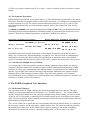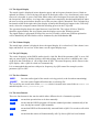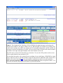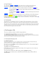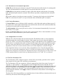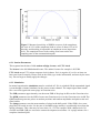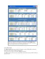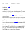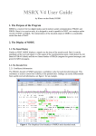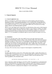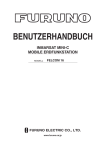
1
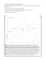
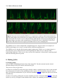
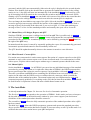
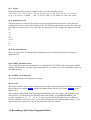
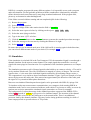
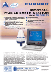
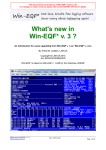
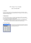
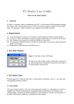
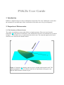
PSK2k User Guide
1. Introduction
PSK2k is a digital mode for scatter at underdense meteortrails. The term "underdense" means that
the ionization is not sufficient to allow a reflection of the radio waves of a given frequency.
2. Properties of Meteorscatter
2.1. The Geometry of Meteor Scatter
The scatter at underdense meteor trails follows a simple geometry. The wave trace from the
transmitter A to the meteor trail defines a cone with the meteor trail as it's rotational axis as shown
in figure 1. The incident wave is scattered into the whole cone. The scattered signal can be heard
where the cone intersects the Earth's surface.
Figure 1. Geometry of scattering radio waves at a weakly ionized meteor trail. The
signal transmitted at A can be heard on the line of intersection of the green cone
with the Earth's surface colored in cyan.
2.2. The Scattered Signal as a Function of Time
Besides the position of the meteor trail there are several factors which influence the actual signal as
a function of time:
(1) Where are the geometrical ends of the ionized trail?
(2) What is the speed of the meteor while it is building up the meteor trail?
(3) What is the time-constant of ionization decay?
An example is shown in figure 2.
Figure 2. A simulated meteor scatter signal as a function of time. The trail starts at 0.06 s
relatively near to the point of geometrically optimal reflection. This leads to a small leading
oscillation. When the trail reaches the first Fresnel zone the signal has it's maximum. After this
maximum, the signal oscillates while the meteor trail is extended outside the first Fresnel zone.
This oscillation may lead to total fade-out as at 0.22 s because the signal coming from the first
Fresnel zone is already decaying while the trail extends further. The signal phase typically is free
of disturbations in it's central part (first Fresnel zone). Therefore PSK is a useful modulation for
meteor scatter. Slight modifications of the simulation parameters (starting point, meteor speed,
decay) lead to considerably different figures. The first Fresnel zone on the meteor trail has a
length between 2.5 km and 15 km, and the meteor needs 40 ... 400 ms to fly through this zone
(144 MHz). The figure shows a fast meteor flying perpendicular to the radio path.
3. Demands for a Digital Meteorscatter Mode
The very short pings and their occurance at random prohibit from using an explicit change-over.
Therefore a fixed timing is used aligned at full minutes of UTC. Usual half-periods are 30 s
(FSK441) or 60 s (HSCW). PSK2k supports 30 s, 15 s, and 2.5 s. 15 s is good in effective
showers. 2.5 s can be used when accurate time synchronization is guaranteed, and if long bursts
occur frequently. In order to minimize QRM, the calling frequency 144.370 MHz is fixed to 30 s.
The information communicated via a meteor scatter ping is small, and often the interpretation is
ambiguous. Therefore, it is convenient to follow a generally accepted standard QSO-procedure.
There are two standard procedures in use:
European Standard Procedure
CQ AAAAA
AAAAA BBBBB 27
BBBBB AAAAA R27
AAAAA BBBBB RRR
BBBBB AAAAA 73
North-American Standard Procedure
CQ AAAAA
AAAAA BBBBB
BBBBB AAAAA 27
AAAAA BBBBB R27
BBBBB AAAAA RRR
AAAAA BBBBB 73
The report 27 varies, and in FSK441 it usually is repeated two times. The same is true with the RRR
and the 73. If the QSO is established then one of the callsigns may be omitted.
4. Properties of the PSK2k Mode
4.1. Modulation
PSK2k uses binary Phase-Shift-Keying at a rate of 2000 bits/s. The pulse shape is a sinc-function.
The result is a minimum-energy modulation, not a constant-amplitude modulation.
4.2. Signal Spectrum
As a consequence of the sinc-pulse, the spectrum of the transmitted signal has a rectangular shape
of 2000 Hz width.
4.3. Code Words
Every code word of PSK2k has 258 bits. Since the Baudrate is 2000 bits/s a code word is
transmitted in 129 ms. Identical code words are transmitted continuously.
4.4. Synchronization
Every sixth bit of a code word (bits 1, 7, 13, 19, ... , 247, 253) belongs to a synchronization pattern
The synchronization pattern is a Hadamard code of 43 bits:
0100101001110111110001011100000100011010110.
Another part of the packet is the binary address. There are two types of addresses:
The general address used for all transmissions addressed to everybody, i.e. CQ calls, QRZ calls,
and QSTs. The general address has the binary pattern
1101010000001111100110011011011011011011011011011.
The private address is used to address a target callsign. It is unique for every callsign. The address
for DJ5HG for example is
0000111101011001010101101010011100100011101010101.
The encoding of the private address is specified in the PSK2k documentation (7.1. and 7.2).
If the synchronization records a hit then the two addresses are correlated with the corresponding bits
of the packet and the best fitting address is taken. Then the carrier phase is detected from the bits of
the synchronization pattern and the bits of the address, and the phase then is interpolated to the
remaining data bits of the code word. This yields 166 soft bits for the decoding process.
4.5. Code Formats
In all cases three nested codes are used. The outer convolutional code (the channel code) is for error
correction. The inner code is for detection of remaining errors. It is mainly this code that prevents
from display of garbage. The third code is the source code which translates the bit arrays into
displayed text output. There is a plausibility check at this stage which refuses the display of
callsigns that do not comply with the syntax of callsigns.
There are several coding schemes for different message types:
4.5.1. CQ, QRZ, QST, CQ qtf
These four messages communicate (a) a callsign of 10 characters in case of CQ or QRZ or some
general message of 10 characters in case of a QST or a callsign of less than 10 characters plus the
QTF in a resolution of 30° pus the chosen period and (b) the selection 'CQ', 'QRZ', 'QST', or CQ qtf.
The selection is encoded by two bits. Callsigns and general messages are restricted to text of 10
characters of the PSK2k-alphabet. They are translated into binary patterns of 54 bits. So with the
two selection bits we have a total of 56 source information bits. If a callsign has less than 10
characters, the last character is used to transport the information on the QTF and the period.
The inner code adds 15 check bits for final error detection resulting in 71 bits. The channel code
encodes the 71 bits by a rate-1/2-convolutional code of constraint length 13 (tail ended). As a result
there are 166 bits. These bits are interleaved with the synchronization pattern and the address as
mentioned above giving the total of 258 channel bits.
After the receiver recorded a hit with the general synchronization pattern, the 166 soft bits are
decoded by the Viterbi algorithm resulting in a binary pattern of 71 bits. The first 56 bits are used to
generate the 15 check bits. If any of these generated check bits differs from the received check bits
(bits 57...71) then the message is discarded. The probability to get correct check bits by random is
1/32749. To get the rate of displayed false decodes the rate 1/ 32749 has to be multiplied with the
rate of false hits which is less than 0.01. So the amount of displayed garbage is very small.
The codes used in PSK2k are unmodified linear codes. Therefore, the all-zeroes word is a correct
codeword. It would decode to QST: //////////. This special output is caught and never
displayed. It only occurs at random if heavy birdies are present and not blanked out by the
birdieblanker.
4.5.2. ToCall de MyCall with or without Report
Instead of the selection of the CQ-message here the two following bits encode the report:
00 = no report; 01 = 0dB; 10 = 3dB; 11 = 6dB.
MyCall is encoded the same way as in a CQ. But the 15 check bits are generated from the 56 source
bits plus the address pattern bits. This ensures that the address correlation is included in the check.
This is important because active callsigns may be very similar. Then the address correlation often
will show hits from similar callsigns. These hits are discarded after the check.
4.5.3. ToCall de MyCall plus Personal Message
A ten-character message is translated into a 54-Bit binary pattern. Then 17 check bits are generated
from the 54 bits plus the address pattern. The channel code is the same as above.
4.5.4. ToCall de MyCall plus Roger and Report or 73
The source information is only three bits encoding the 5 different messages
R 0dB,
R 3dB,
R 6dB,
RRR, TNX 73.
15 check bits are generated from these 3 bits plus ToCall and MyCall. The pattern of 18 bits is
encoded by a rate-1/9-convolutional code of constraint length 10 (tail biting). The result is a code
word of 162 bits.
4.5.5. Contest Format
It is a severe drawback of meteor scatter QSOs until now that the communicated information is
limited to the basic QSO-information by practical reasons. PSK2k offers the option of a contest
message format that contains: SNR-report + #decodes-report + roger + Maidenhead locator +
contest number + QTF + TX-PWR + antenna gain. The restrictions are:
(1) only three SNR-reports are possible: 0dB, 3dB, 6dB.
(2) only five reports for number-of-decodes are possible: 1, <4, <8, <16, >15
(3) full Maidenhead locator like 'JO53IM' (18*18*10*10*24*24 = 18662400 possibilities).
(4) the absolut maximum contest number is 1416, usually it is restricted to 1...1000.
(5) the QTF is rounded to values in steps of 5°. So only values 0°, 5°, 10°, 15°, ... are possible.
(5) only 8 TX-powers are allowed:
10W, 25W, 50W, 100W, 250W, 500W, 1kW, 2kW.
(6) only 8 antenna gains are allowed: 0dB, 3dB, 6dB, 9dB, 12dB, 15dB, 18dB, 21dB.
The full information has 3756320096256000 possibilities which corresponds to 51.74 bits. So the
information is encoded into a source code of 52 bits. 17 check bits are added which guarantee an
extremely low false-decode rate of 1/131071 times the rate of false synchronization hits. The same
convolutional code as in 4.5.1-3 is used. Therefore the sensitivity of the PSK2k receiver for such a
message is exactly the same as for a CQ-call or a reply to a CQ.
The contest format communicates the addressed callsign only in the synchronization pattern which
is used for correlation but not for transmission of information. Both callsigns additionally are
contained in the 17 check bits which effectively work as a lossy compression. Therefore, it is
necessary to run the North-American standard procedure with the reply to a CQ simply containing
the callsigns and no report (message 4.5.2.). Receiving such a message without a report should
generally be interpreted such that the caller wants to get the full information of the contest format
even if there is no contest running. This is done automatically in all AutoModes.
The additional costs of the contest mode are:
(1) An additional message transfer of the North-American standard procedure.
(2) The very sensitive transmission 4.5.4. of roger + report is replaced by the less sensitive contest
format.
4.6. The Standard Procedures
PSK2k differs from FSK441 in two major aspects: (1) The information is protected by code and by
check bits. Therefore a repetition within a code word is nonesense. (2) Callsigns are communicated
by three different ways: (a) The explicit and uncompressed transport via a CQ or a call. (b) The
uncompressed transmission in a synchronization pattern. And (c) the compressed form in some
check bits.
Let AAAAA and BBBBB be the protected callsigns and let HA and HB be the synchronization patterns
containing the full callsign information. Information which is compressed into check bits is set in
brackets. Then the two standard procedures as realized by PSK2k are as follows:
European Standard Procedure
North-American Standard Procedure
CQ AAAAA (CQ A)
CQ AAAAA (CQ A)
HA BBBBB 27 (B A 27)
HA BBBBB (B A)
HB R27 (A B R27)
HB 27 (A B 27)
HA RRR (B A RRR)
HA R27 (B A R27)
HB 73 (A B 73)
HB RRR (A B RRR)
HA 73 (B A 73)
It should be noted that decoded information is immediately discarded if any of the check bits
differs. As a consequence, displayed garbage is extremely rare. The protection of communicated
information is so powerful, that a station can run PSK2k in an automatic mode, where PSK2k
replies to incoming calls and runs the QSOs to the final 73 without any interaction by the operator.
4.7. Code Division Multiple Access (CDMA)
As a consequence of the meteorscatter geometry, stations at distances larger than a few km see a
completely different situation on the same frequency. PSK2k additionally introduces the CDMAtechnique to reduce the computational effort and the display of unwanted decodes. PSK2k only
displays CQ and QRZ calls, and QST-messages and messages addressed to the stations callsign.
Running QSOs of other stations remain invisible. This is the same situation as in Frequency
Division Multiple Access (FDMA) where different QSOs run on different frequencies, and only one
frequency is actually in use by the amateur.
5. The PSK2k Graphical User Interface
5.1. The Decoder Windows
The upper half of the GUI figure displays the decoded messages into four windows. The upper
window is for messages addressed to all listeners, i.e. CQ, QRZ, QST etc.. The second window
displays all messages addressed to the operator's callsign as long as the sending call is not selected
as the "to call" for a possible or running QSO. The third window shows all messages of the actual
QSO. The lowest decoder window displays all messages sent by the last two QSO-partners after the
QSOs had been stopped at this end.
The "to call" either can be typed into the corresponding edit field (in manual mode) or a callsign in
the two upper windows can be selected by a double mouse click. The latter immediately generates
the standard procedure texts. If this is done while a QSO is running, a non-modal warndialog
demands for a user decision between "abort the running QSO" or "do not start a new QSO".
5.2. The Signal Display
The actual signal is displayed in time domain (upper) and in frequency domain (lower). Both are
updated in realtime. A received ping will appear in the display after a very short latency at the same
time as it is decoded. A green vertical bar marks where the actual signal overwrites the display of
the last period. If the latency is so large that a signal is not completely decoded and displayed when
the next receiving period starts, then the rest of the previous signal is discarded. This is marked by a
horizontal red bar at the right end of the display. Actually this should only happen in the "RX Only"
mode, where the computer cannot finish the decoding process in the TX-period.
The spectrum display shows the signal between 0 and 3000 Hz. The region of 500 to 2500 Hz
should be approximately flat. At program start the displays start at the following period.
The signal display is generated in front of the receiver. Possibly visible non-Gaussian pulsenoise
will be blanked by the NB. Birdies will be eliminated by the birdieblanker BB.
5.3. The Volume Display
The actual input volume is displayed above the signal display. It is colored red, if the volume is too
high, and black if it is too low. In the latter case the signal display stops.
5.4. The QSY Display
The carrier frequency of the PSK2k audio signal is 1496 Hz. But if the parameter QSY is set to ON
and you start a QSO by double-clicking a decoded callsign, then the carrier is shifted by the value
of the df in the clicked line (if |df| is larger than 45 HZ). The actual frequency shift is shown in the
QSY display. After a QSO it returns to 0 automatically.
It is recommended that stations with precise frequency (by QPS-control for example) set the
parameter QSY to OFF.
5.3. The Save Buttons
audio :
Save the audio signal of the actual receiving period (or the last when transmitting)
graphic :
Save the actual GraphicalUserInterface as a bitmap file
The saved files are stored in the folder records which is located in the same folder as PSK2k.exe
and this helpfile PSK2k_UserGuide.pdf.
5.4. The Auto Buttons
There are four buttons in the auto bar which allow different levels of automatic operation:
manual
means that operation has to de done manually.
QSO
means that the PSK2k program will run the standard procedure automatically if the
user already has started a QSO manually.
reply
means that PSK2k will automatically start and finish a QSO if it records a call to this
station.
CQ
means that this station will automatically call CQ after a QSO has been finished.
Figure 3. The Graphical User Interface (GUI) of PSK2k. Decoded messages are displayed in
four decoder windows: The upper window for CQ, QRZ and QST, the window for pending calls
to this station waiting for a QSO, the window for received QSO-information, and the window for
messages sent after confirmation of a QSO. The lower half of the GUI shows the actual standard
procedure to the right, and signal displays and control buttons to the left.
The GUI can be resized. The fonts then are resized too. To save the GUI-position on the screen
click an apply button in the parameter-GUI.
The messages shown here are replayed from recordings of tests with Roger, GW4WND. A single
mouse-click on a line in a decoder window copies the line into the clipboard. In the actual case, a
double-click on the decoded CQ-line generated the standard procedure texts and started the
QSO. Since the AutoMode CQ is on, the QSO ran automatically. After reception of either 73 or
CQ from GW4WND, the program will start a CQ from this station.
5.5. The TX-Buttons
The TX-buttons TX 1st and TX 2nd define which of the two half-periods should be the
transmission period. Be sure to use the right one if you are on the calling frequency.
RX only
is for (1) monitoring a frequency without intention to run QSOs (in manual ) or
(2) with AutoMode reply to wait for calls in either period (never use it on the calling
frequency!) or
(3) with AutoMode reply1st or reply2nd to wait for calls and reply in the selected
period only.
TX only
is for continuous test transmissions. Never use this button on the calling frequency!
Pushing the STOP TX button while a transmission is running stops the actual transmission.
Pushing it again (now it is the SEND -button) resumes the transmission. This button is labeled RX
in the RX-periods and disabeled then.
5.6. The Menu Bar
The menu bar is self-explaining. The file / Exit option of the menu guarantees a clean exit from
PSK2k, but it may take a while because it stops all concurrent processes in an ordered sequence.
The option file / show decoded calls opens an edit window which displays all up to now decoded
callsigns with dates of last decode and of last QSO. If there are false decodes, please delete those
lines. Then delete the figure to store the entries.
6. The Parameter GUIs
There are two different windows available to input parameters:
The Standard Parameter Window is the usual window to set PSK2k parameters.
The Test Parameter Window additionally allows ping-simulation and a fast switch between three
different station callsigns with different parameter settings.
6.1. The Standard Parameter GUI
6.1.1. Basic Parameters
Some basic parameters are set via a parameter-GUI. It is shown in figure 4. If this GUI is not
already open then select "options" in the menu bar of the main GUI.
Here enter your actual callsign, possibly including guest prefix or /P etc. The maximum length of
the callsign is 10 characters.
The locator is the full Maidenhead locator.
UTC-clock means UTC minus computer clock in hours. So it is negative if you live at least one
hour east from Greenwich.
You can select the COM-port for TRX-control with the COM-port parameter.
The PTT parameter offers the choice of the DTR or the RTS lines (choose /DTR or /RTS for
inverted levels).
Figure 4. Window with standard parameters. Some
parameters may be entered as an editable text (callsign and
QSO number for example), others may be selected in a
pulldown menu. Parameters shown on light-green
backgroud may be changed within a running QSO.
There is a pulldown menu for the soundcard ID for both, input and output. These IDs are not the
same as in other programs which use the soundcard. You have to try it out.
Options for the (half-)period are 2.5s, 15s, and 30s. The period 30s was introduced by FSK441, and
it probably should also be the standard of PSK2k. If the rate of useful pings is as high that more
than one ping is decoded within a period of 30s then 15s surely is the better choice.
TX-delay sets the gap between the edge of the PTT signal to switch the TX on and the start of the
audio signal to modulate the TX (in milli seconds).
The CW-ID is sent by keying the PSK2k signal. This is not a clear-tone CW-signal, but the PSK2kreceiver can well decode pings of this signal. So the time while the ID is sent is not lost for a QSO.
You can transmit the CW-ID: ever / every 10 minutes / every 20 minutes / never.
The options of SAVE are none, auto, and all. auto means saving of usefully decoded signals. The
save audio button in the main GUI is colored audio , when the actual recording will be saved. All
audio recordings are *.WAV files at sample rate 8000 and mono with 8 bits per sample.
6.1.2. Parameters for Automatic Operation
STOP TX sets the timeout in minutes to stop the TX after the last useful decode of a running QSO.
The TX will automatically be started again if a new decode has been received.
STOP QSO sets the timeout in minutes to abort a QSO after the last useful decode of a running
QSO. An aborted QSO cannot be resumed. This timeout especially is implemented for automatic
operation.
#73 sets the number of periods you want to send the 73-message after having received the final
RRR. It is convenient to send 73 or CQ to inform the other end that the QSO is complete.
6.1.3 Contest Parameters
If Contest Mode is set to ON then a QSO is started by a call of the other station without report. If
one station runs contest mode and the other runs normal mode, then the other station automatically
is enforced to run the QSO in contest mode too.
The QSO-number for the next QSO can be set here. It is incremented automatically. So you need
not to enter it every QSO.
Power and Antenna Gain can be selected for the contest format. These values should be set in any
case, because a call could enforce you to run in contest mode.
6.1.4. Sample Rate Correction
While the PC-clock determines the start and end of the TX and RX periods, it is the samplerate
which determines the actual length of a packet. If the sample rate is correct, then the length of a
packet is 0.12900 s. It is shorter if the samplerate is larger. If the difference of the samplerates used
at both ends of a communication path is so large that the length of the packet sent differs by about
one bit or more from what the receiver defines as it's packet length, then decoding degrades. The
dependence of the rate of correct decodes on the error of the samplerates is shown in Figure 5.
If the samplerate factors are set correctly, then no degradation occurs. Also the detected offset
values df are corrected (a samplerate error of 1% leads to a frequency offset of 15Hz). But the
output carrier frequency is not corrected. This therefore may be wrong by up to 10 Hz or more even
if GPS-synchronization is used for the rig. Ratefactors between 0.95 and 1.05 are allowed.
6.2. The Test Parameter GUI
The Test Parameter GUI is shown in figure 5. If this GUI is not already open then select "options"
in the menu bar of the main GUI and choose test parameters.
The Test Parameter GUI has 6 segments. All these segments have three lines named "operator 1",
"operator 2", and "operator 3". The parameters can be changed interactively. But they are not
applied immediately to the running PSK2k program. In order to guarantee consistent parameter sets
you have to push the corresponding check box in the apply column. Then all parameters of all six
segments of that line are activated. If you edit somewhere in the lines of the currently selected
operator then the checkbox in the apply column is deselected to notify that the recent changes are
are not applied.
The three lines offer the possibility to set standard values for three different situations which can be
selected by one mouse click in the apply column.
Figure 5. Measured sensitivity of PSK2k on errors of the samplerate.
An error of 0.2% of the samplerate leads to a loss of about 15% of all
decodes, and decoding is impossible at samplerate errors larger than
0.6%. The samplerate factor is the scaling error between the two
rampling rates of the communication path.
6.2.1. Station Parameters
This segment has the three fields station callsign, locator, and UTC-clock.
The locator is the full Maidenhead locator. The author's locator for example is JO53IM.
UTC-clock means UTC minus computer clock in hours. So it is negative if you live at least one
hour east from Greenwich. Please click on the fields, type in the information, and enter by the enter
key. Do not forget to finally apply the changes.
6.2.3. Simulation
In normal operation the simulation must be switched off. If it is switched ON the transmitted signal
is sent through a channel simulator for the meteor scatter channel. The output signal then sounds
like a received signal with some pings in Gaussian noise.
The SNR parameter approximately sets the mean SNR of the pings in dB over the Gaussian noise.
The QRM parameter sets the SNR of some non-Gaussian noise over the Gaussian noise in dB. The
QRM simulator generates pulses at random positions and random amplitudes and pulse trains and
some birdies.
The #pings parameter sets the mean number of pings in the half-period. If the SNR is low, some
pings may be buried in noise. So the rate of decodable pings usually is considerably lower than the
#pings parameter. This value may be lower than 1.0, 0.25 for example. With a halfperiod of 30
seconds and SNR=3dB two crosswise connected computers need about 10 / #pings minutes for a
complete simulated QSO.
Figure 5. The Test Parameter GUI. Parameters may be edited at any time.
Changes are applied by selecting one of the operators via the apply check
boxes. Only parameters for Simulation, Operating, and Automatic Operation
are directly applied without use of the apply check box.
6.2.4. TRX-Control
The TRX-Control works on the old RS-232 interface or with a USB-to-RS-232 interface.
Otherwise use the VOX to trigger the transmission.
You can select the COM-port with the COM-port parameter.
The PTT parameter offers the choice of the DTR or the RTS lines (choose /DTR or /RTS for
inverted levels).
6.2.5. Soundcard Parameters
The samplerate may be chosen as 8000, 16000, 32000, and 48000. The computational effort
increases with the samplerate. On the other hand, PSK2k uses 2000 Baud, so a bit is only 4 samples
long, if the samplerate 8000 is selected. The bit-synchronization is better at higher samplerates. But
there is no diffrence in sensitivity when 32000 or 48000 are used.
There is a pulldown menu for the soundcard ID for both, input and output.
Input mode and output mode may be chosen as real, complex, or dual. real means the usual audio
signal from and to an SSB-transceiver. complex means that the PSK2k program interpretes the left
and right audio input as the real and imaginary part of an analytic signal. Correspondingly, the
output signal is generated the same way. The option dual is not implemented until now. It is
intended to run the PSK2k program independently on the left and right audio channels to allow
running two transceivers at two antennas (with QTF differing by 90°).
6.2.6. Operating Parameters
The CW-ID is sent by keying the PSK2k signal. This is not a clear-tone CW-signal, but the PSK2kreceiver can well decode pings of this signal. So the time while the ID is sent is not lost for a QSO.
Options for the (half-)period are 15s, 30s, and 60s. 30s were introduced by FSK441, and probably
should also be the standard of PSK2k. If the rate of useful pings is as high that more than one ping
is decoded within a period of 30s then 15s surely is the better choice.
NB and BB define the default for the activation of the noise blanker and the birdie blanker.
If the edit field for QRG is not blank then CQ calls will direct the repliers to that QRG. Be sure
your receiver listenes on that QRG. Otherwise blank this field.
The options of SAVE are none, auto, and all. auto means saving of usefully decoded signals. The
save audio button in the main GUI is colored audio , when the actual recording will be saved.
6.2.7. Automatic Operation
The Auto Mode defines the default of the auto buttons.
Repeat QSO sets the minimum time difference in days between automatically started QSOs. In
simulations it should be set to zero to enable repetition of QSOs with the same callsigns
STOP TX sets the timeout in minutes to stop the TX after the last useful decode of a running QSO.
The TX will automatically be started again if a new decode has been received.
STOP QSO sets the timeout in minutes to abort a QSO after the last useful decode of a running
QSO. An aborted QSO cannot be resumed. This timeout especially is implemented for automatic
operation.
#73 sets the number of periods you want to send the 73-message after having received the final
RRR. It is convenient to send 73 or CQ to inform the other end that the QSO is complete.
6.2.8. Contest Parameters
If the contest check box is selected then then a QSO is started by a call of the other station without
report. If one station runs contest mode and the other runs normal mode, then the other station
automatically is enforced to run the QSO in contest mode too.
The QSO-number for the next QSO can be set here. It is incremented automatically.
Power and Antenna Gain can be selected for the contest format.
7. Checking the Interaction of PSK2k with the TRX Hardware
7.1. Parameters
Set the parameters Standard Parameter GUI according to chapter 6.1.
Choose the right soundcard ID (see 6.1.1.)
Set the AutoMode to manual .
7.2. Computer Clock
Check the computer clock. The difference to the UTC-minutes should be as low as possible because
any difference to the clock of the other station is lost time for the communication. If you are on the
calling frequency this time interval even will be stolen from all amateurs which hear your signal as
QRM within their reveiving (half-)period. If synchronization of the computer clock with internet
time is used check it's precision. The difference of internet time to UTC often is too large.
7.3. Test Received Audio
Set the TRX-buttons of the PSk2k-GUI to RX Only . Switch your rig on and adjust the volume such
that the value of the input volume display in the PSK2k-GUI is between -10 dB and +10 dB
(background not black or red).
If the spectrum display shows one or more peaks (birdies) change the frequency of your receiver by
about 500 Hz. The birdies in the spectrum should move then by the same frequency difference, but
with inverse direction. No matter of birdies, go back to the frequency of your choice. PSK2k is very
robust against birdies.
7.4. Test Signal Output
Connect your earphones to the sound output of your computer. Select the standard message "QRZ
de YourCall" by the button to it's right and choose TX 1st or TX 2nd and check wheather PSK2k
switches the output signal ON and OFF correctly.
7.5. Test TRX Control
Connect the PTT of your TRX with the RS-232 interface. Choose the appropriate values for COMport and PTT in the Parameter-Gui and apply these values by selecting the apply check box in the
first columns of the Stations Parameters. Choose TX 1st or TX 2nd and select a message to be
sent, for example "QRZ de YourCall". The TX should go on air now in the chosen half-periods
sending the generated signal of the soundcard output.
The PSK2k signal does not have a constant-amplitude. The TX-output power therefore must be
adjusted to an SSB-level if the PA is peak-power limited (most solid-state PAs).
7.6. Check of Processor Load
Figure 6. Processor load caused by PSK2k. It is a squarewave with low load in the transmission
periods and a higher mean load in the receiving periods plus peak loads in case of detected pings.
The mean load level of the receiver without the ping load depends on the chosen sampling rate.
The upper figure was taken with a sampling rate of 16000, the lower with 48000. If your load
looks more like that in the lower figure you should choose a lower sampling rate .
The PSK2k receiver needs considerable computational power. Figure 6 shows an examples of
PSK2k with change-over every15 seconds and two different sampling rates.
The PSK2k receiver decodes the incoming signal continuously. If there are very many pings or a
burst then the receiver falls back in the receiving halfperiod. But it tries to catch up in the
transmitting halfperiod. If the receiver does not succeed completely it discards the remaining signal
and starts decoding the next period.
8. Making QSOs
8.1 Starting QSOs
Select TX1st or TX2nd in the bottom line of the main GUI. Turn the antenna into the desired
direction and type this QTF into the edit field for QTF.
There are two ways to get active:
(a) Wait for a decoded CQ-call in the upper decoder window. A double-mouse-click on the decoded
line will generate all entries of the standard procedure and it will automatically select the reply to
this CQ as the next transmission. If you select the AutoMode QSO or higher the QSO now will run
automatically.
(b) Start a CQ-call by pushing the CQ in the standard procedure. If the AutoMode reply is selected,
replies to your CQ will appear in the third decoder window, the standard procedure is automatically
generated, and the QSO runs automatically. Otherwise the reply is displayed in the second decoder
window. Here double click on the decoded line to generate the standard procedure for the calling
station. As in (1) the QSO will now run automatically if the AutoMode QSO is selected. In a pileup all incoming calls will remain in the second decoder window until the QSOs are made. While
running a QSO in AutoMode reply , you can double click on one of the lines in the second decoder
window to select the callsign you want to work next after the current QSO is completed.
You can change the AutoMode at any stage of the QSO. Select the AutoMode manual if you want
to send a special private message edited in the last line of the standard procedure section. Such a
message will only be decoded at the other end, if you are in a QSO, i.e. if the other station got a
message of line 3 or line 4 of the standard procedure and actually runs your call as it's tocall.
8.2. Manual Entry of Callsigns, Report, and QTF
Similar to FSK441 you can enter a callsign into the field to call. This is possible only in manual
mode. Pressing the normal button or the contest button will generate the corresponding standard
procedure for the entered call. A standard procedure can be deleted by pressing the clear button to
the right of the QTF entry.
In manual mode the report is entered by repeatedly pushing the report. It is automatically generated
in automatic operation and cannot be altered manually in that case.
The QTF should be updated manually whenever the antenna is turned to a new direction.
8.3. Mixed Normal / Contest QSOs
If a station runs contest mode it sends contest reports. Reception of a contest report forces the QSOautomatic to reply with a contest report even if it runs in normal mode. If a contest station is called
with a report, it replies with a contest report without roger. A manual operator should do the same.
8.4. Manual QSOs
Set the AutoMode to manual . As in FSK441 you can select any individual message of the standard
procedure by pressing the button to it's right side. Other than in FSK441, the PSK2k-program does
not accept messages that violate the correct sequence if an AutoMode is selected ( QSO and more).
Therefore you cannot send RRR before something like R 3dB has been received from the other
station. At the other end, the PSK2k receiver would not decode a message which is outside the
defined order of the standard procedure. The manual option only was implemented to cope with
computer/program/rig problems. If everything works well, then at least the AutoMode QSO should
be used because it's operation is faster and more reliable than a human can be.
9. The AutoMode
As already mentioned in Chapter 5.4. there are five levels of automatic operation.
The first level manual corresponds to the operation of FSK441. In this mode you have to interpret
the decoded information of the third decoder window by your own to support your decision on
which line of the standard procedure should be sent next.
The second level QSO allows the fully automatic operation of the standard procedure after a QSO
has been started.
The third level reply allows the PSK2k-program to generate and operate the standard procedure
after a specific call to this station had been recorded. It is not necessary to call CQ in this mode. It is
sufficient that some other station knows your QRG and period.
In the fourth level CQ PSK2k will call CQ whenever it is not in a QSO. Replies to the CQ will
automatically lead to automatic operation of the corresponding standard procedures. If replies to
your CQ are recorded from more than one station in the same period then the sequence of QSOs
will be determined by the editable priority list (see 11.4).
10. Automatic Setting of Period and TX1st / TX2nd
If a station is in ReceiveOnly mode, it listenes in both half periods 1st and 2nd. If a decoded CQ
call is double-clicked, then the received information about the period is used to reset the local
setting to that of the CQ-call, and the correct TX1st or TX2nd will also be chosen if the received
ping is sufficiently far away from the changeover region (1.5 seconds). The previous settings are
restored after the QSO
If a station is in both, ReceiveOnly and reply mode, it must be called in the correct period length
of that station. It is recommended to use periods of 30 seconds generally in that case. But it can be
called in either halfperiod TX1st or TX2nd . If the station in ReceiveOnly mode wants to
monitor both halfperiods, but only reply to calls in TX1st , then the reply button can be clicked to
reply1st or reply2nd or back to reply . This is especially useful on the calling frequency 144.370
MHz, where only TX2nd should be used in central Europe.
11. Files
All files used and generated by PSK2k are located in the same folder. The location depends on the
system you use. Usually it is something like ... "your private folder"\documents\MATLAB\PSK2k .
The pathes to all files are printed into the DOS-window at program start.
10.1. PSK2k.exe
This is the PSK2k program to be executed on your computer. At it's first start it will be unpacked
internally which may take a while, please be patient.
10.2. decodedtext.txt
This text file prints all messages which are decoded by the PSK2k program in chronological order.
The line format is as follows (# means number of successful decodings of the same message in the
last 10 minutes):
time
#
Δf
dB
address
de
call
12:26:25
2
+37
-1
DJ5HG
de SM2CEW
report
nr. locator QTF
PWR
ANT
R 6dB <8 017 KP15CR 210° 500W 15dB
is in UTC. # is the number of decodes of the displayed text within the last 10 minutes. Δf is
the deviation between the frequency of the decoded signal and your RX frequency. dB is the SNR
of the received codeword. The received report consists of the R and the SNR in dB. In contest mode
the number of decodes at the other end is added.
time
10.3. log.txt
PSK2k automatically gererates a logfile with lines of the following format:
startconnect conf
stop callsign
14:22 14:25 14:29 14:30 GW4WND
rptsent sent QTF rptrcvd rcvd locatr QTF
0dB
<4 022 240° R6dB
pwr
ant distance
<8 136 IO82KM 210° 500W 15dB
932km
10.4. prefixpriority.txt
This text file may be edited by the operator prior to operation in the auto mode. It lists the mostwanted prefixes line-by-line in descending order. The PSK2k-program only uses this file if there are
more than one replies to your CQ in the same receiving period. For example, the author's list could
be:
5A
7X
3V
OJ0
OH0M
C3
HV
T7
10.5. decodedcalls.mat
This is an internal file for managing all callsigns that were recently decoded. Do not change or
delete this file.
10.6. PSK2k_parameters.mat
This is used to save the actual parameters. If you delete this file, PSK2k will start using the default
settings. If PSK2k does not start, please delete this file (or rename it for later restauration) and try to
start PSK2k again.
10.7. PSK2k_UserGuide.pdf
This is the document you currently are reading.
10.8 records
This folder contains all wave files automatically recorded (Operating Parameter SAVE) or manually
taken with the save button audio , and all screenshots taken with the save button graphic of the
PSK2k-GUI.
All records are taken mono with samplingrate 8000 and one byte per sample. The filenames start
with 'PSK2k_rec' followed by the ISO 8601 date in the format 'yyyymmddTHHMMSS' and
possibly extended by '_G', '_C', '_Q', or '_P' if the record could be decoded. In case of different
decodes within the same record, the '_Q' for QSO-information supercedes the others, and a '_C' for
call to this station supercedes a decode for the general decoder window.
12. Resuming a QSO after Program Failure
PSK2k is a complex program with many different options. It is impossible to test such a program
under all situations. Several probable problems with the soundcard are eliminated by automatic
failure detection and restart. But surely, many bugs remained undetected. If the program fails,
please try to characterize what had happened.
If the failure occured within a running and not completed QSO do the following:
(1) Restart the program
(2) Select manual operation
(3) Type the callsign of the other station into the field of to call:
(4) Select the same report as before by clicking on the report: 0dB
3dB
6dB
(5) Select the same #pings as before
(6) Type in the same QTF as before
(7) Click the normal button or the contest button to generate the standard procedure messages
(8) Select the message to be sent next by clicking the button to it's right
(9) Select TX 1st or TX2nd
Be aware that you are in manual mode now. If the QSO traffic is running again in both directions,
you can select a different auto mode of your choice, for example QSO .
13. Simulation
If the simulation is switched ON in the Test Parameter GUI, the transmitted signal is sent through a
channel simulator for the meteor scatter channel. The output signal then sounds like a received
signal with some pings in Gaussian noise. For explanation of the simulation parameters see Chapter
5.2.
The simulation generates a trail of charged particles that builds up at a meteor velocity v. The trail is
cut by random at both ends. The effect of diffusion is mapped to a decay of charges. The received
signal at time t is the sum of the individual signals scattered by all remaining charges at time t .
The computation is very similar to that of an antenna simulator. Figure 2 gives an example of a fast
meteor flying across the radio path. If the meteor has approximately the direction of the radio path
the signal is very smooth without phase distortions.
Burst are not simulated. But adequate burst signals can be generated with SNR=20, #pings=300.
To simulate reality-near meteorscatter communication, two computers, both running PSK2k in
simulation mode, can be cross-connected with two audio cables. Even nearer to reality, two near-by
stations can crosswise transmit the simulated signal (somewhere on 70cm for example).
The background of a selected message in the standard procedure segment of the PSK2k-GUI is
colored red instead of yellow to give notice of a simulated output. The insertion of the channel
simulator and this color are the only differences to the normal mode. There is an additional
processor load by the channel simulator. This may lead to timing problems resulting in a shift of
some output periods or sporadic misses of TX periods.
14. The Rate of False Decodes
PSK2k does not search for pings or bursts by some sort of pattern recognition. In contrast, the audio
input signal is continuously decoded. This way PSK2k in principle can decode about 7 received
packets per second. This is nearly one million potential decodes per day. This huge number is
reduced by an internal significance level of the synchronization to about 100000 sync hits per day in
pure Gaussian noise. None-Gaussian noise can increase the number of hits. All these hits would
lead to false decodes in the display if there would not be the check bits and the plausibility checks.
Extensive tests over many weeks of continuous operation showed zero false decodes at both ends.
Even running PSK2k on a heavily used QRG in an SSB-contest over 24 hours gave no decodes.
Nevertheless, there still is a small probability of getting syntactically correct false decodes in the
display. And the probability will be increased, if many stations are active on the same frequency.
14.1. Non-Fatal False Decodes
The most probable false decodes are of the type
TOCALL de MYCALL : free text of 10 characters
In the automode they have no relevance. In manual mode such messages also have no relevance
because it is extremely improbable that they display senseful text.
Also false QSTs like
QST: L7NCD6ADRF
can occur. QSTs are messages to all operators. They do not carry any QSO information, and they
are simply displayed by the PSK2k program without notice of their contents. A QST message will
not be displayed, if the SNR is less than 0dB. But it is stored for later comparison. If it occurs once
more then it is displayed independently of it's SNR.
False decodes of the types
CQ de CALLSIGN or QRZ de CALLSIGN
can occur. Most of them violate the syntax of amateur callsigns. The plausibility check usually
prevents their display.
Strong birdies can lead to the all-zeros codeword, which is decoded to
QST: //////////
This message is forbidden and never displayed.
False decodes of the type
mycall de falsecall
with a correct mycall but false calling call with or without report also can occur. Automatic reply
requires at least two decodes of the same callsign if the SNR is less than 0dB. That guarantees
sufficient security against QSOs with aliens.
14.2. Fatal False Decodes
A fatal decode is a decode which leads to an invalid QSO. Such false decodes in principle can
occur, but they should be extremely rare.