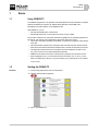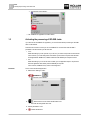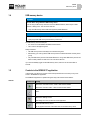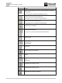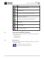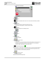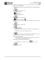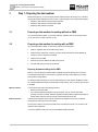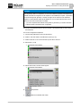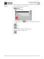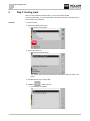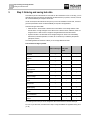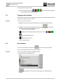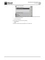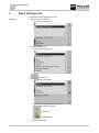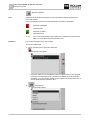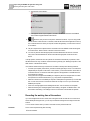
1
Operating Instructions for BASIC-Terminal, TRACK-Guide II ISOBUS-TC Version: V2.20141016 30302436-02-EN Read and follow these operating instructions. Keep these operating instructions in a safe place for later reference. Company details Document Operating Instructions for BASIC-Terminal, TRACK-Guide II Product: ISOBUS-TC Document number: 30302436-02-EN From software version: 04.10.04 Original language: German Copyright © Müller-Elektronik GmbH & Co.KG Franz-Kleine-Straße 18 33154 Salzkotten Germany Phone: ++49 (0) 5258 / 9834 - 0 Fax: ++49 (0) 5258 / 9834 - 90 Email: [email protected] Homepage: http://www.mueller-elektronik.de Table of contents Table of contents 1 Basics 5 1.1 Using ISOBUS-TC 5 1.2 Starting the ISOBUS-TC 5 1.3 Activating the processing of ISO-XML tasks 6 1.4 USB memory device 7 1.5 Controls in the ISOBUS-TC application 7 1.6 Screen layout in the ISOBUS-TC application 9 1.6.1 1.6.2 1.6.3 Master data screen Task list screen Task data screen 9 10 12 1.7 Taking care of your ISO-XML master data 12 1.8 Exiting the ISOBUS-TC application 14 2 Quick instructions 15 2.1 Quick guide for FMIS users 15 2.2 Quick guide for users with no FMIS 15 3 Step 1: Preparing the data medium 18 3.1 Preparing a data medium for working without an FMIS 18 3.2 Preparing a data medium for working with an FMIS 18 3.2.1 Exporting implement settings for the FMIS 18 3.3 Preparing a data medium for farmpilot 20 3.4 Creating the "taskdata" folder 20 4 Step 2: Creating a task 22 5 Step 3: Entering and saving task data 24 5.1 Entering task data in a new task 25 5.2 Terminaling the Task Data 25 5.3 Changing static task data 26 5.4 Save task data 26 6 Step 4: Starting a task 28 7 Step 5: Using the ISOBUS-TC application during work 30 7.1 Entering target rates 30 7.2 Selecting the implements 31 7.3 Configuring the list of connections 33 7.4 Recording the working time of the workers 34 7.5 Selecting the task processing phase 35 7.6 Counters on the ISOBUS job computer 36 7.7 Documenting filling and emptying 37 30302436-02-EN V2.20141016 3 Table of contents 7.8 Navigating to the Field 39 8 Step 6: Stopping work 40 8.1 Stopping a task 40 8.2 Pausing a task 40 9 Step 7: Finishing the documentation 42 9.1 Transferring tasks using a USB memory device 42 9.2 Upload a set of tasks to the farmpilot portal 42 9.3 Using text files 43 9.4 Printing the results 43 10 Important files stored on the USB memory device 44 11 Notes 45 4 30302436-02-EN V2.20141016 Basics Using ISOBUS-TC 1 1 Basics 1.1 Using ISOBUS-TC The ISOBUS-TC application is an application from Mueller-Electronics which establishes an interface between the ISOBUS job computer, the TRACK-Leader application and the FMIS (Farm Management Information System) on the ISOBUS terminal. With ISOBUS-TC, you can: ▪ Plan and edit ISO-XML tasks on the terminal, ▪ Edit ISO-XML tasks which you have planned on the PC using your FMIS. All information contained in the order will be transferred by ISOBUS-TC to specialized applications of the terminal. This means that each application is doing exactly what it can do best: ▪ The position of the field is transferred to FIELD-Nav. It can therefore navigate the vehicle directly to the field. ▪ The field boundaries, guidance lines, prescription maps and other information about processed fields stored in the task are transferred to TRACK-Leader. The field can be therefore processed. ▪ The target rates are transferred from a prescription map to the ISOBUS job computer. In this way, you do not have to worry about inputting the target rates. ▪ ISOBUS-TC documents work duration, and the persons, implements and resources involved. ▪ After completing the work, you can transmit all of the work results to a PC. To do so, you can either use a USB memory device [➙ 42] or the farmpilot [➙ 42] Internet portal - if it is available in your country. 1.2 Starting the ISOBUS-TC Procedure 1. Insert an empty USB memory device into the terminal. 2. Open the "Selection Menu" application: ⇨ The following screen appears: 3. Click on line "ISOBUS-TC". 30302436-02-EN V2.20141016 5 1 Basics Activating the processing of ISO-XML tasks ⇨ The following screen appears: 1.3 ⇨ The "ISOBUS-TC" application has been started. Activating the processing of ISO-XML tasks If you want to use the ISOBUS-TC application, you must first activate the processing of ISO-XML tasks on the terminal. There are two scenarios in which you can use ISOBUS-TC. Use the "Work with ISO-XML?" parameter to set the scenario you will work with: ▪ "Yes" Select this setting if you set up tasks on your PC or if you want to set up tasks on the terminal. In this instance, you must always start a task before you start work. Only then does the data exchange between ISOBUS-TC, TRACK-Leader and the ISOBUS-job computer function. ▪ "No" Select this setting if you do not use tasks. Instead, you use application maps in shp format or enter the application rates directly into the ISOBUS-job computer. In this instance, ISOBUS-TC only works in the background. Procedure This is how to activate the application: 1. Switch to the "Settings" screen: | ISOBUS-TC | ⇨ The following screen appears: 2. - Select and click on the "Work with ISO-XML?" line. ⇨ The mode will change with each click. 3. Set the parameter to "Yes". 4. 6 - Restart the terminal. 30302436-02-EN V2.20141016 Basics USB memory device 1.4 1 USB memory device NOTICE Data loss when using a different USB memory device If you are using a USB memory device that is not from Müller-Elektronik, there may be contact problems or writing errors. This can lead to data loss. ◦ Only use USB memory devices that were supplied by Müller-Elektronik. NOTICE Data loss when removing the USB memory device prematurely ◦ Always logout the USB memory device before you take it out. The USB memory device has two jobs: ▪ It is used to move data between the FMIS and the terminal. ▪ This is used for storage during work. Always remember: ▪ The USB memory device must always be connected during work. ▪ After working, you must log out the USB memory device so that the data will be correctly saved. [➙ 42] ▪ Only use USB memory devices from Mueller-Electronics. Using other USB memory devices can lead to contact problems or write errors. This can lead to data loss. If you have accidentally logged out the USB memory device, remove it and re-insert it after 10 seconds. 1.5 Controls in the ISOBUS-TC application In this chapter, you will find an overview of the most important function icons that you may come across in the ISOBUS-TC application. The ISOBUS-TC application is operated using the rotary knob and the function buttons. Controls Function icon Meaning Switch to the "Task data" screen – When a task has been started. Switch to the "Task list" screen – When no task has been started. Return Switch to the "Settings" screen Enter settings as to how you want to use the application. Remove the USB memory device Will only appear if the folder "Task data" exists on the USB memory device. 30302436-02-EN V2.20141016 7 1 Basics Controls in the ISOBUS-TC application Function icon Meaning Prepare an empty USB memory device for use with the ISOBUS-TC application without farmpilot. The "Task data" folder is created on the USB memory device. Download a set of tasks from the farmpilot portal Will only appear if you are connected to the farmpilot portal Upload a set of tasks to the farmpilot portal Will only appear if you are connected to the farmpilot portal Search for a task or master data Terminal the field in FIELD-Nav The function icon is grey when the function has been deactivated. Create a new task Copy existing task Split stopped task Starting a task Opens the TRACK-Leader application Stop task Confirm Save task data Start working time recording for worker Stop working time recording for worker Start working time recording for implements 8 30302436-02-EN V2.20141016 Basics Screen layout in the ISOBUS-TC application 1 Function icon Meaning Stop working time recording for implements Start navigation to field The function icon is grey when the function has been deactivated. Start navigation to unloading location Only appears if your terminal has the "Slave" status within a group of vehicles. The function icon is grey when the function has been deactivated. Enter filled capacity Enter emptied capacity Configuring the list of connections 1.6 Screen layout in the ISOBUS-TC application There are three important screens in the "ISOBUS-TC" application which you need to get to know: ▪ Master data screen [➙ 9] ▪ Task list screen [➙ 10] ▪ Task data screen [➙ 12] 1.6.1 Master data screen The "Master data" screen is the start screen for the ISOBUS-TC application. From this screen you can access all other screens. You can identify the "Master data" screen by this icon. You will find the icon in the upper section of the screen. 30302436-02-EN V2.20141016 9 1 Basics Screen layout in the ISOBUS-TC application Master data screen In the main section of this screen, you will see folders which contain the data stored in the FMIS. If you move the cursor right down to the bottom using the rotary knob, you will be able to see additional folders containing master data. 1.6.2 Task list screen The "Task list" screen contains the names of all tasks stored on the USB memory device. You can identify the "Task list" screen by this icon. You will find the icon in the upper section of the screen. Task list screen Beneath the task list you will find the background information about the respective task you selected. You can identify the status of the task by the color of the icon preceding the name of the task. Tasks whose names are preceded by an asterisk are copies of other tasks. The following table contains an overview of all icons used to mark the different types of tasks. Icons 10 Icon Icon colour Meaning light yellow Tasks that have not been started yet dark yellow Paused tasks green Started tasks 30302436-02-EN V2.20141016 Basics Screen layout in the ISOBUS-TC application Icon Icon colour Meaning red Stopped tasks 1 Tasks processed by the "Master" Tasks that have not been started yet Tasks that have not been started yet are those that have never been started. These tasks may include: ▪ Newly created tasks ▪ Copies of existing tasks – if the name of the task is preceded by an asterisk ▪ Tasks imported via the farmpilot portal or the FMIS which have not yet been started. Paused tasks Paused tasks are tasks which have been interrupted and not fully completed. A task will be paused automatically if another task is started while the first task is still in progress. Paused tasks are terminaled in the farmpilot portal as not yet completed. Started tasks Started tasks are tasks that have been started and are currently being processed. Stopped tasks Stopped tasks are tasks that have been stopped. As a rule, these are tasks which have been completed. However, the system is not capable of verifying whether the tasks have been fully completed. Therefore, only stop a task if you have completed it. Stopped tasks are terminaled as completed tasks in the farmpilot portal. Tasks processed by the Master Appears only in cooperation with the farmpilot portal. All tasks processed by the fleet leader (Master) will be labeled as such. Every time the Master starts to process a new task, you will be notified by a pop-up window. 30302436-02-EN V2.20141016 11 1 1.6.3 Basics Taking care of your ISO-XML master data Task data screen The "Task Data" screen contains all information about the task you selected. The "Task data" screen will be terminaled when you select or create a task on the "Task list" screen. You can identify the "Task data" screen by this icon. You will find the icon in the upper section of the screen. The colour of the icon will vary depending on whether the task has been started or newly created. Green – the task terminaled has been started. Yellow – the task terminaled has not been started. Task data screen Name and number of the task Serial task number. TSK means TASK . Cursor Selects a line that can be clicked on with the rotary knob. Task processing stage Indicates what stage of completion the task is at [➙ 35]. Function icons section Icons that can be pressed on this screen. Task data section Contains detailed information about the selected task Counter section Only appears when you start the task. The task data section may also contain the following icon: This means that the task data also contain an application map. The icon is used for information purposes only. 1.7 Taking care of your ISO-XML master data We define master data as data that is on the USB memory device and is needed to specify tasks more precisely. To access the master data on the USB memory device: ▪ From the FMIS - You can save the master data from the FMIS to the USB memory device. 12 30302436-02-EN V2.20141016 Basics Taking care of your ISO-XML master data 1 ▪ You can set up the master data on the terminal and save it to the USB memory device. The disadvantage with this method is that the data cannot be read with any external program. You cannot delete it either. NOTICE Data loss ◦ Create the master data only at one spot: either in the FMIS or on the terminal. ◦ Do not change the method. NOTICE Non-compatible FMIS Not every FMIS is capable of importing modified master data. ◦ Before starting to change or create master data, check whether you can import your FMIS tasks with changed data. You do not have to maintain the master data in all of the categories. The selection depends on the farm size and on the intended use. Possible master data Icon Data Contains Customers* Lists with customers. Farms* Lists with farms. Farm equipment Lists with connected ISOBUS job computers and with other implements equipment for which the working time can be recorded. Product groups* Lists with products, fertilizers, pesticides, etc. Fields* Field name, areas, prescription maps**, GPS coordinates of: field boundaries, obstacles, guidance lines and more. Useful for people working with TRACK-Leader or FIELD-Nav and working on the same field over and over again. Worker* Lists with workers * - Optional master data. ** - Can only be imported through the FMIS. The categories "Customers", "Farms" and "Fields" are linked hierarchically. This means that you must always assign a farm to a customer, a field to a farm or a customer, etc. Procedure To create new master data on the terminal: A USB memory device with the "Taskdata" folder is inserted in the terminal. 1. Open the ISOBUS-TC application. 30302436-02-EN V2.20141016 13 1 Basics Exiting the ISOBUS-TC application 2. Select a folder with the master data: "Fields", "Farms", "Customers", "Workers" or "Products". 3. - Create a new data set. ⇨ A form appears. 4. Fill in the fields. Once you have saved the entry, you can no longer change the data. 5. 1.8 - Save the entry. Exiting the ISOBUS-TC application You can exit the ISOBUS-TC application at any time. This will neither finish nor cancel the tasks. Procedure 1. - Call up the "Selection menu" application. ⇨ The selection menu appears. 2. Open the desired application. 14 30302436-02-EN V2.20141016 Quick instructions Quick guide for FMIS users 2 2 Quick instructions 2.1 Procedure Quick guide for FMIS users The USB memory device contains an ISO-XML task that you created with an FMIS. You have created the task using implement data that you previously transferred from the terminal. [➙ 18] You have set the "Work with ISO-XML?" parameter to "Yes". 1. Insert the USB memory device into the terminal. 2. Open the application start screen: | ISOBUS-TC | 3. 4. - Press. ⇨ The task list appears. - Click on the desired task. ⇨ The "Task data" screen appears. 5. ⇨ ⇨ ⇨ ⇨ 6. 2.2 - Start the task. The task will be started. The ISOBUS job computers connected to the terminal will be automatically added to the task. The target rates are transmitted to the ISOBUS job computer. Field boundaries, prescription maps and other field data will be transferred to TRACKLeader. - As soon as you have reached the field, switch over to TRACK-Leader to perform the work. (It may be necessary to previously configure TRACK-Leader.) Quick guide for users with no FMIS If you are working without a FMIS, you have to enter the master data, such as the field name or customer name directly on the terminal. Procedure 1. Insert the USB memory device into the terminal. 2. Call up the ISOBUS-TC application: | ISOBUS-TC | 30302436-02-EN V2.20141016 15 2 Quick instructions Quick guide for users with no FMIS ⇨ The following screen appears: 3. 4. 5. 6. 7. - Press. - Make sure that the answer is set to "Yes" for the "Work with ISO-XML?" parameter. - Press. ⇨ The "Task data" folder is created on the USB memory device. ⇨ The following message appears: "The folder has been created" - Confirm. ⇨ A function icon appears on the "Settings" screen: - Press. 8. - Press. ⇨ The task list appears. 9. - Create a new task ⇨ A form appears. ⇨ In this form, you can perform all settings for the task. When starting up for the first time, it is especially important to enter the field name and the target rate. For more information, please read: Step 3: Entering and saving task data [➙ 24] 10. - Activate the following line: 11. Because there is no master data on the USB memory device yet, create a new data set with the field name and area. By doing this, you can reuse the field boundaries and guidance lines for new tasks on this field. For more information, please read: 12. - Create a new field. ⇨ A "PFD" form appears. 13. Enter the field name on the topmost line. 16 30302436-02-EN V2.20141016 Quick instructions Quick guide for users with no FMIS 2 14. Enter the area on the "0.00 ha" line. 15. NOTICE! Be precise here. Once you have saved the data, you can no longer change the field size. 16. 17. 18. 19. - Press to confirm the entries. ⇨ A list of fields appears. - Select the field. ⇨ Field name appears in the task. - Press to confirm the entries. - Activate the following line: 20. Here, you must enter the quantity per hectare and the units of the product to be applied by the implement. 21. - Press to confirm the entries. 22. - Start the task. ⇨ The task will be started. ⇨ The ISOBUS job computers connected to the terminal will be automatically added to the task. ⇨ The target rate is transmitted to the ISOBUS job computer. 23. - As soon as you have reached the field, switch over to TRACK-Leader to perform the work. (It may be necessary to previously configure TRACK-Leader.) 24. Process field in TRACK-Leader. ⇨ All field data that is created during processing is saved by ISOBUS-TC in the task: Field boundaries, guidance lines, transmitted target rates, etc. 25. After working, open the ISOBUS-TC application again. ⇨ A screen with the active task appears. If not, press 26. 30302436-02-EN V2.20141016 on the start screen. - Finish the task. 17 3 3 Step 1: Preparing the data medium Preparing a data medium for working without an FMIS Step 1: Preparing the data medium Before starting to work, you have to prepare the data medium that you will be using on your terminal. The procedure differs depending on how you work. Continue reading in one of the following chapters: ▪ Preparing a data medium for working without an FMIS ▪ Preparing a data medium for working with an FMIS ▪ Preparing a data medium for farmpilot 3.1 Preparing a data medium for working without an FMIS If you are working without FMIS, you must first create the "Taskdata" folder on the storage medium. [➙ 20] Then you can create a new task. [➙ 22] 3.2 Preparing a data medium for working with an FMIS If you are working with an FMIS, you first have to perform the following steps: 3.2.1 1. Create a "Taskdata" folder on the USB memory device 2. Create and start a blank task. In this way, all of the relevant information from the ISOBUS job computer is saved to transmit it to the FMIS. 3. Create a task in the FMIS. 4. Save the task from the FMIS to the USB memory device. 5. Insert the USB memory device into the terminal. Exporting implement settings for the FMIS Before you can plan with tasks with the FMIS for ISOBUS implements, the FMIS has to know the current implement description. This includes, for example: Geometry of the implement, ID number, working width, holding capacity. To deliver this data to the FMIS, you need to create a blank task on the terminal. ISOBUS-TC writes the complete implement description in the taskdata.xml with the task. Then you have to open this task in the FMIS. When to perform? You must perform this step in the following instances: ▪ Before you plan the first task. ▪ If you change implement parameters in the job computer. This can include: Work width, geometry or number of nozzles. When the application identifies that the implement description in the task differs from that in the job computer, it will not allow the task to start. Mode of operation In this step, all parameters stored in the job computer of the implement are saved in an XML file. These data is provided with a unique ID number. The unique ID number is also the serial number of the connected jobcomputer. You can find it in the "Selection menu" application. You have to repeat this step once more for each ISOBUS-capable implement. 18 30302436-02-EN V2.20141016 Step 1: Preparing the data medium Preparing a data medium for working with an FMIS 3 NOTICE If you are planing a task for an implement, you must ensure that the properties of the implement in the FMIS match with the configuration of the implement in the ISOBUS job computer. If parameters such as the working width, geometry or number of hoppers do not match, the work data will be assigned to a new implement created by the ISOBUS-TC. You can still continue to work, but you will have to correct the counters later in the FMIS. ◦ If you use an implement with different working widths or geometries, you create an individual implement profile in the FMIS for each configuration. Procedure You have connected the terminal to the job computer of the implement that you wish to add to the master data. You have configured the implement. 1. Insert an empty USB memory device into the terminal. 2. Create a "Task data" folder on the USB memory device [➙ 20] 3. Create a new task You do not need to enter any task data for this task. 4. Start the task. [➙ 28] ⇨ The following screen appears: 5. Wait several minutes, until the counters appear. ⇨ The following screen appears: 30302436-02-EN V2.20141016 6. - Stop the task. 7. Switch to the "Master data" screen. 19 3 Step 1: Preparing the data medium Preparing a data medium for farmpilot 8. - Write the task data to the USB memory device. ⇨ The implement data is saved to the "Taskdata.xml" file located in the "Taskdata" directory on the USB memory device. 9. Wait until the data have been written and read. ⇨ The function icon will be hidden. 10. Remove the USB memory device from the terminal. 3.3 ⇨ You have transferred the implement parameters to the USB memory device. Preparing a data medium for farmpilot You will receive data from the portal if they are sent by a dispatcher. The dispatcher will always send the data as sets of tasks that consist of one or more tasks. Procedure You will receive the set of tasks from the dispatcher as follows: You have opened the ISOBUS-TC application. You have inserted a USB memory device into the terminal. NOTE! The USB memory device must not contain a folder named "TASKDATA". If this folder does exist, you must save [➙ 42] the existing data to the USB memory device. 1. The dispatcher will send you the task data. ⇨ The following notification appears: “New task data available“ 2. - Confirm. ⇨ The data is not on the terminal yet, but is ready to be downloaded. 3. - Load data from the portal. (The arrow on the icon must point downwards) ⇨ The following message appears: "Start downloading task data?" 4. - Confirm. ⇨ The data is being loaded. 5. Open the "Task list" screen. ⇨ All tasks from the set of tasks will appear on the "Task list" screen. ⇨ You have received a set of tasks from the dispatcher. You can process the tasks from the set of tasks. 3.4 Creating the "taskdata" folder The Taskdata folder serves as the storage location for all ISOBUS-TC-relevant files: ▪ File with all tasks and master data: taskdata.xml ▪ Prescription maps: bin files If you insert an empty USB memory device into the terminal, you can create the folder directly on the terminal. 20 30302436-02-EN V2.20141016 Step 1: Preparing the data medium Creating the "taskdata" folder Procedure 3 1. Insert an empty USB memory device into the terminal. 2. Call up the ISOBUS-TC application: | ISOBUS-TC | ⇨ The following screen appears: ⇨ If the following function icon created. 3. 4. appears on this screen, the folder has already been - Press. - Press. ⇨ The "Task data" folder is created on the USB memory device. ⇨ A function icon appears on the "Settings" screen: 30302436-02-EN V2.20141016 21 4 Step 2: Creating a task 4 Step 2: Creating a task When you have prepared the storage medium, you must now create a new task. If you are using farmpilot, you cannot create tasks on the terminal. Instead you must wait until you receive a task from the dispatcher. Procedure To create a new task: 1. Switch to the "Master data" screen. ⇨ The following screen appears: 2. Click on the "Tasks" line. ⇨ The following screen will appear: The "Task list" screen may show tasks that have already been created, as shown in the picture. 3. Now there are two ways to create a task: - Create a new task 4. Option a: ⇨ The following screen appears: 22 30302436-02-EN V2.20141016 Step 2: Creating a task 4 ⇨ The new task was named by the terminal with the current date and time. The task has not been saved yet. - Copy selected task. In the copied task, you can adopt or change all of 5. Option b: the task data from the original task and then process it as a new task. ⇨ The following screen appears: ⇨ The new task will be added to the list and marked as a copy with an asterisk. ⇨ You have created a new task. You now have the following options: ▪ You can fill the task with task data. [➙ 24] ▪ You can start the task. [➙ 28] ▪ You can save the task. [➙ 26] 30302436-02-EN V2.20141016 23 5 5 Step 3: Entering and saving task data Creating the "taskdata" folder Step 3: Entering and saving task data Task data are precise characteristics of a task that can be summarized in a form. In this way, you can describe each task more precisely and therefore document the work you perform, for whom, and how the connected ISOBUS job computer should react. On the one hand, the task data serves to improve your own documentation. On the other, it serves to give work specifications to the connected ISOBUS job computers and applications. There are two types of task data: ▪ Static task data – this task data is entered once in the FMIS or on the storage medium of the terminal and is no longer changed. This is data such as customer names, addresses, fields. It is assigned once to a task and can no longer be changed after the task has been started. ▪ Dynamic task data – this task data can be changed during work. Some of it is automatically determined (connected implements, counters, list of connections) or entered by the operator (task phase, worker) The following table shows the times at which you can change different task data. Time at which a change is possible Parameter Task is new and Task has alwas not saved yet ready been saved Task is started. Designator + - - Customer + - - Farm + - - Field + - - Farm equipment + + + Target rates + + + Person in charge + - - Worker + + + Work process + - - Filling/Emptying - - + Counter - - + List of connections - + + Sensors - + + The following sections tell you how to change task data in tasks that have not been started yet. As soon as you start a task, read this section: Step 5: Using the ISOBUS-TC application during work [➙ 30] 24 30302436-02-EN V2.20141016 Step 3: Entering and saving task data Entering task data in a new task 5.1 Procedure 5 Entering task data in a new task You have created a new task, but have not yet saved it. The "Task data" screen appears. 1. - Select the line with the date. ⇨ The data input screen appears. ⇨ If you cannot see the first line, it can be because the task has already been saved in the past. In this case, you must create a new task. 2. Enter a name for the task. 3. If you want to document what you do on which field and for whom, tap one of the following Customer , Farm, Field. However, this is not mandatory. categories: ⇨ A list with the customers, farms and fields saved in the master data appears. ⇨ If the list is empty, it means that the master data is empty. In this case, read this section: Taking care of your ISO-XML master data [➙ 12] 4. Select the information from the list that match your task. 5. Ignore the category "Target rates" in this step. When starting the task, the terminal automatically recognizes which ISOBUS job computers are connected. Then you can also enter the target rates. 6. In the category, you can select a work process, if it is a category that is supported by your Farm Management Information System. 7. - Exit the form. ⇨ The following message appears: "Do you want to save your changes?" 8. Confirm. 5.2 ⇨ You have entered the task data and saved the task. Terminaling the Task Data It does not matter whether you have created the task on the terminal or in the FMIS. You can always view the details. Procedure To display more information on the task data: The "Task data" screen has been called up. 30302436-02-EN V2.20141016 25 5 Step 3: Entering and saving task data Changing static task data The task has already been saved. 5.3 1. Click on the line with the task data: , , , ⇨ A form appears with more detailed information. . The line must contain data for this. Changing static task data In this section, you will learn how to change the static task data for a task that has been saved but not yet started. For example, for the copy of a task. Procedure The "Tasks" screen is called up. 1. Option a: If the task has never been started before, click on the task with the rotary knob. 2. Option b: If the task has been started before in the past, press Then click on the copy of the task with the rotary knob. ⇨ The screen with the task data appears. 3. 4. 5.4 to copy the task. - Click on one of the following lines and hold for two seconds: , , , ⇨ A list of available data will appear. - Select data from the list. ⇨ You have changed the task. Save task data You can only save the task if the function icon appears on the "Task data" screen. Once saved, most of the task data can no longer be changed. Procedure You have created a new task and entered the task data. You are presently on the following screen: 1. 26 possible. - Save task data. This function icon will only appear if saving the task data is 30302436-02-EN V2.20141016 Step 3: Entering and saving task data Save task data 5 ⇨ The following screen appears: The saved task appears on the "Task list" screen. The name consists of the date and time when the task was created. ⇨ You have saved the task. The "Task data" screen will terminal new parameters: ▪ Farm equipment ▪ Worker You will only be able to alter these parameters once you start the task. 30302436-02-EN V2.20141016 27 6 Step 4: Starting a task 6 Step 4: Starting a task You can start every task regardless of its status. Procedure 1. Switch to the "Task List" screen. ⇨ The following screen appears: 2. Click on the desired task. ⇨ The following screen appears: 3. - Start the task. ⇨ The following screen appears: ⇨ The task has a new status: Green – task started. ⇨ The following function icons appear: - Stop the task. - Navigate to field. ⇨ You have started the task. 28 30302436-02-EN V2.20141016 Step 4: Starting a task 6 You now have the following options: ▪ You can select farm equipment used for the task. [➙ 31] ▪ You can select workers. ▪ You can let the application navigate you to the field. [➙ 39] (Only if FIELD-Nav has been activated.) To learn how to do this, read the FIELD-Nav operating instructions. ▪ You can stop the task. [➙ 40] 30302436-02-EN V2.20141016 29 7 7 7.1 Step 5: Using the ISOBUS-TC application during work Entering target rates Step 5: Using the ISOBUS-TC application during work Entering target rates If you want to define a target rate for the ISOBUS job computer, you can do so through a task. The target rate tells the ISOBUS job computer how much product should be applied by the metering units of the implement. To doing so, you have the following options: ▪ You can enter a target rate in the "Target rates" field of the task. This value is transmitted to the ISOBUS job computer, so that the job computer works according to this definition until the task is completed. ▪ For implements with more than one metering unit, you can enter a target rate for each metering unit. ▪ You can add a prescription map to the task in the FMIS and then start the task on the terminal. In this case, pay attention to the following: – The terminal sends only those target rates to the job computer that are required at the current GPS position. – If you are working with prescription maps, only the average target rate appears under the "Target rates" parameter. You cannot change the individual target rates of the prescription map. – If supported by the ISOBUS job computer, you can use up to four prescription maps. Every prescription map then contains target rates for one metering unit of the implement. The following picture shows an overview of the input fields: Overview of the input fields Line for the target rate These rates are transmitted to the ISOBUS job computer. Product quantity Implement part Measurement unit Products If the applied product is a mixture, in this area you can enter which products are contained in the mixture. Product type Area for a second target rate You will see the following icons on the screen: Mixture Name of the mixture to be applied 30 30302436-02-EN V2.20141016 Step 5: Using the ISOBUS-TC application during work 7 Selecting the implements Implement part If the implement has more than one hopper or metering system, here you can assign the target value to an implement part. Product If the mixture consists of several products, you can specify the individual products here. There are three input fields to the right of each icon, each of which can be selected and clicked on with the cursor. You can use the input fields to specify the mixture to be applied, the quantity and the product composition. The application will not check whether the quantities of the individual products total the target rate of the mixture. Procedure The task is started. 1. On the "Task data" screen, click on the following line: ⇨ A list of target rates appears. 2. Click on the first field beside the icon. 3. Enter the first target rate. 4. To the right, select the unit and the product (optional). 5. Click on the field beside this icon: ⇨ A list of connected ISOBUS job computers appears. 6. Select the job computer. ⇨ A list of implement parts to which you can assign a target rate appears. Their type and designator depend on the ISOBUS job computer. 7. - Select the implement part to which you want to assign a target rate. ⇨ A list of target rates appears. The selected implement now appears beside the ⇨ You have assigned a target rate to an implement part. icon. 8. Repeat these steps for the next target rate. To do so, use the remaining empty fields. 9. 7.2 - Confirm input and save. ⇨ The ISOBUS job computer adopts the target rate. Selecting the implements This step requires that you select the implements needed for the task. You can add any number of implements and farm equipment. The terminal records the work time. It don't have to be Implements with an ISOBUS job computer. You can also add other equipment to count the time. Controls Add implement Reactivate deactivated implement (press and hold) 30302436-02-EN V2.20141016 31 7 Step 5: Using the ISOBUS-TC application during work Selecting the implements Deactivate implement Icons Implements can be activated or deactivated. For each implement the terminal calculates time for which it was activated. The icon preceding the implement name indicates whether it is activated or deactivated. Implement is deactivated (red background) Implement is activated (green background) no icon Procedure 1 If you are processing the task using an implement not intended for this purpose in the FMIS, no icon will appear before the implement's name. You can select an implement from a list as follows You have started a task. 1. On the "Task data" screen, click on the following line: ⇨ The following screen appears: ⇨ The screen contains a list of all implements and farm equipment which you have assigned to this task. If the planed implement is connected to the ISOBUS, then it will be activated immediately. If you are processing the task using an implement not assigned to this task, no icon will appear before the implement's name. 2. 32 - Add implement. ⇨ A list of equipment appears: 30302436-02-EN V2.20141016 Step 5: Using the ISOBUS-TC application during work Configuring the list of connections 7 3. Click on the desired implement or equipment on the list. For instance, a tractor with which you want to pull a sprayer. ⇨ The following screen appears: ⇨ You will find the following information below the name of the implement: - For activated implements: Date and time of activation - For deactivated implements: Date and time of deactivation 4. Add more implement if you need. Procedure 2 ⇨ You have selected an implement. To activate a deactivated implement: 1. On the "Task data" screen, click on the following line: 2. Select a deactivated implement from the list. 3. 7.3 - Press and hold for 3 seconds. ⇨ Implement will be activated. Configuring the list of connections The list of connections indicates the ISOBUS job computers from which the terminal will load the geometries of the connected implements. This geometry is required in order to calculate the position of all implement components on the basis of the GPS signal. Only in this way are precise parallel driving and section switching possible. Procedure If you are using the ISOBUS-TC application, you can configure the list of connections as follows: All ISOBUS job computers required for a task are connected. The task is started. 1. Open the task data. 2. 30302436-02-EN V2.20141016 – Open the screen with the list of connections. 33 7 Step 5: Using the ISOBUS-TC application during work Recording the working time of the workers ⇨ The following screen appears: ⇨ A list appears with all of job computers, controllers and ECUs connected to the ISOBUS. The connectors appear between these devices. 3. - Press the rotary knob on the top line to select the first device. If you are using an ME terminal to which a GPS receiver is connected, insert the ME-Tractor-ECU application in the top line. If another terminal or tractor job computer contains the geometry, it can be used for the list of connections. 4. The job computer of the implement that is connected to the rear ISOBUS socket should appear on the second line. Select a device in the line for the second device. 5. You now only need to select the appropriate connector between the two devices. Press the rotary knob in the line between two devices and select the appropriate connector for each device. In simple systems, the terminal can set up the list of connections automatically. In particular, when the ME terminal is the only unit which contains the tractor geometry (see: Entering the position of the GPS receiver. in the terminals manual) It can however still be necessary to set the list of connection manually in the following instances: ▪ If a tractor job computer (Tractor-ECU), in which the tractor geometry is saved, is mounted as an independent job computer on the tractor. In this instance, you must decide which Tractor-ECU is connected in the list of connections with other equipment: the application on the ME terminal or on the tractor job computer. ▪ If the system cannot organize the ISOBUS job computer by itself. For example when more than one implement is connected to the tractor (e.g.: slurry tanker and planter/seeder). ▪ When the connection to an ISOBUS job computer is interrupted during the start-up of a ISO-XML task. In most cases, the list of connections will be set correctly as soon as you reconnect the ISOBUS job computer. ▪ If this error message appears when starting the terminal: "List of connection is incomplete." ▪ When the following error message appears when starting a navigation in TRACK-Leader: "The device data is still loading." The settings in the list of connections can eliminate this problem. 7.4 Recording the working time of the workers If you have assigned the task to a worker, their working time will be recorded as soon as the task is started. While performing the work, you can stop and start the working time recording and add new workers. You can use this function when you want to document who has performed the work. Procedure This is how to stop the working time recording: A task is started. 34 30302436-02-EN V2.20141016 Step 5: Using the ISOBUS-TC application during work Selecting the task processing phase 7 1. Open the current task. 2. On the "Task data" screen, click on the following line: 3. Mark the name of the worker who is finishing work. 4. Procedure - Stop the working time recording. ⇨ The icon beside the worker's name turns red. ⇨ The working time will no longer be recorded. This is how to start the working time recording: A task is started. 1. Open the current task. 2. On the "Task data" screen, click on the following line: 3. Mark the name of the worker who is starting work. Procedure 4. Press and hold the button to restart the working time recording. ⇨ The icon beside the worker's name turns green. ⇨ The working time will be recorded. 5. - Press briefly on the button to add a new worker. ⇨ A list of names of available workers appears. ⇨ The worker will be added to the task. ⇨ The working time will be recorded. This is how to add a new worker: A task is started. 1. Open the current task. 2. On the "Task data" screen, click on the following line: 3. 7.5 - Press briefly on the button to add a new worker. ⇨ A list of names of available workers appears. ⇨ The worker will be added to the task. ⇨ The working time will be recorded. Selecting the task processing phase Setting the task processing phase allows you to calculate the tasks more accurately. The following phases exist: ▪ Driving time ▪ Preparation 30302436-02-EN V2.20141016 35 7 Step 5: Using the ISOBUS-TC application during work Counters on the ISOBUS job computer ▪ Working time ▪ Break ▪ Repair time Procedure 1. On the "Task data" screen, click on the following line: TSK-(task number) ⇨ The following screen appears: 2. Click on the desired phase of task processing. 7.6 ⇨ The new phase is visible on the "Task data" screen. Counters on the ISOBUS job computer The ISO 11783 standard defines several types of counters that can be transmitted by the ISOBUS job computers to the ISOBUS-TC. The texts of the counters are not the same for all manufacturers and job computers. The determined values are generally transmitted in decimal units. ISOBUS-TC does not correct anything. This means, for example, that a working time of 0.33 hours corresponds to 20 minutes. Counting always takes place from the start to the end of a task. 36 Type of counter Unit Total applied quantity. L, kg, piece Total yield L, kg, piece Applied area ha, m2 Driven distance in working position km, m, mm Notes This is generally the applied distance. 30302436-02-EN V2.20141016 Step 5: Using the ISOBUS-TC application during work Documenting filling and emptying Type of counter Unit Driven distance not in working position km, m, mm Time in working position Hours, Minutes, Seconds Time not in working position Hours, Minutes, Seconds 7 Notes The counter will appear on the "Task data" screen. Task data screen with counter Procedure This is how to select the implement for which the counter should be terminaled: A task is started. 1. Click on the line 2. Click on the implement for which the counter should be terminaled. 7.7 Documenting filling and emptying With ISOBUS-TC you can document filling and emptying. The data entered in this procedure will not be exchanged between the ISOBUS job computer and the application. You can evaluate the documented values in the farmpilot portal. Example 1 After weighing a tipper truck, the driver can enter that he has loaded 20 tonnes of maize. Example 2 After spreading 5000 litres of manure with a non-ISO manure truck, the driver can enter the quantity spread as 'emptying'. Controls Function icon Function Enter filled capacity Enter emptied capacity Procedure Thus you can document the filling or emptying of a container for non-ISO implements. You have started a task. 30302436-02-EN V2.20141016 37 7 Step 5: Using the ISOBUS-TC application during work Documenting filling and emptying 1. Open the "Task list" screen. 2. Click on the following line: Filling/Emptying ⇨ The following screen appears: 3. Press the desired function key. - Enter filled capacity - Enter emptied capacity ⇨ The following screen appears: ⇨ You can identify whether you are entering the filled capacity or the emptied capacity by the icon in the upper left hand corner. 4. The screen consists of three columns, in which you can enter data: In the left hand column: Enter quantity. In the middle column: Enter the unit. l = litres t = tons In the right column: Select from a list the product to be filled or emptied. 5. - Leave screen. 6. The following notification will appear: “Save changes?“ 7. Click "Yes" to confirm. ⇨ The "Task data" screen appears. 38 30302436-02-EN V2.20141016 Step 5: Using the ISOBUS-TC application during work Navigating to the Field 7.8 7 Navigating to the Field When starting a task, you can let the computer navigate you directly to the field. To be able to use this function, you require: ▪ An activated license for FIELD-Nav ▪ Activated map material for FIELD-Nav ▪ A field with field boundaries in the master data Procedure FIELD-Nav with map material is activated on the terminal. The map material is on the USB memory device. The target field is saved in the master data with field boundaries. 1. Create a new task. 2. In the task data, select the field to which you want to be navigated. 3. Start the task. 4. - Start the navigation to the field. ⇨ A FIELD-Nav application window appears. 5. Use the application as described in the FIELD-Nav instructions. 30302436-02-EN V2.20141016 39 8 Step 6: Stopping work Stopping a task 8 Step 6: Stopping work You can stop a task at any time. You must decide yourself whether this task has been fully processed or must be processed further. If you stop the work, you must decide what should happen to the task. Depending on whether the task was fully processed or must be processed further, you have the following options: ▪ Stopping a task ▪ Pausing a task 8.1 Stopping a task When you stop a task, farmpilot will consider this task to be fully completed. Therefore, you should only stop tasks if they have been completed. Procedure 1. Switch to the "Task data" screen. 2. 8.2 - Stop the task. ⇨ The task will be stopped. ⇨ The task will be marked red on the "Task List" screen. Pausing a task You can pause a task if you need to interrupt your work, but have not yet completed the task. A task will only be paused if you start another task. Procedure You have started a task and are on the "Task data" screen: 1. Switch to the "Task list" screen while the task is started. 40 30302436-02-EN V2.20141016 Step 6: Stopping work Pausing a task 8 ⇨ The following screen appears: The active task is marked in green. 2. Click on any task, preferably one that has been stopped. ⇨ The following screen appears: 3. - Start the task ⇨ The active task will be paused and the task you have selected will be started. 4. - Stop the task. ⇨ The task will be stopped. ⇨ The original task will be marked in yellow on the "Task List" screen. ⇨ The paused task is now marked in yellow. 30302436-02-EN V2.20141016 41 9 Step 7: Finishing the documentation Transferring tasks using a USB memory device 9 Step 7: Finishing the documentation If you have finished a task or set of tasks, you can export the results. The following options are available to you: ▪ Transfer tasks to the FMIS using a USB memory device ▪ You can transfer the work results to the PC as a text file. ▪ You can print the results. 9.1 Procedure Transferring tasks using a USB memory device You have completed all tasks. All tasks are marked red on the task list. 1. Open the "Master data" screen. 2. - Write the task data to the USB memory device. ⇨ Wait until the flashing. icon disappears and the LED on the USB memory device stops 3. Remove the USB memory device. 4. Connect the USB memory device to the farm computer. 5. Import and process data with the FMIS. 9.2 Procedure Upload a set of tasks to the farmpilot portal You have received the tasks through farmpilot. You have completed all tasks. All tasks are marked in red on the task list. 1. Open the "Master data" screen. ⇨ The following screen appears: 42 2. - Upload a set of tasks to the farmpilot portal ⇨ The following notification will appear: “Start uploading task data?“ 3. - Confirm. ⇨ The data is being loaded. 30302436-02-EN V2.20141016 Step 7: Finishing the documentation Using text files 9 ⇨ The transmitted task data will no longer be displayed on the terminal. ⇨ A new folder is being created on the USB memory device: "TaskData_work(serial number)". Backup copies of the tasks sent to the farmpilot portal will be created in this folder. 9.3 ⇨ You have uploaded a set of tasks to the portal. Using text files Each time you finish a task, a text file is created on the storage medium. You can open this file on your PC with any text editor. From the top, the following information can appear in the record: ▪ Task designator ▪ Customer ▪ Farm ▪ Field ▪ Person in charge ▪ Start and stop times ▪ Task duration, of which: – Working time – Driving time – Preparation – Break – Repairs – Offloading time ▪ ▪ ▪ ▪ Involved worker Used implements Target rates Creation date, creation time The information appearing in your documentation always depends on how precisely you have entered the data into the task and which information was transmitted by the ISOBUS job computer to the ISOBUS-TC app. 9.4 Printing the results If an ISO printer sold by ME is connected to the terminal, you can print the results of any finished task as a record. The record can show the same information as in a text file that is automatically created. See section: Using text files [➙ 43] Procedure The ISO printer is connected to the terminal and activated. You have finished the work. 1. Stop the task. 2. Open the task data. 3. 30302436-02-EN V2.20141016 - Start printing. 43 10 10 Important files stored on the USB memory device Important files stored on the USB memory device All task data, field data and implement data will be saved on the USB memory device. This makes it possible to transfer these data between the terminal and the FMIS. All files have standardized names which may not be altered. The folders that must be stored on the USB memory device vary depending on whether you are using the terminal in conjunction with the farmpilot portal or transfering the data from the Farm Management Information System using a USB memory device. Important files: The files specified here may appear in various folders. TASKDATA.xml – A file containing all task data stored in the Farm Management Information System. The file will be saved from the FMIS either onto the hard drive of the farm computer or onto a USB memory device. If you use the farmpilot portal, the file will be created automatically in the directory named "TaskData_work". If working without the farmpilot portal, you must copy the file from the hard drive to the directory "TASKDATA" stored on the USB memory device. The Taskdata.xml file must not be larger than 2 MB. Files that are too large may cause problems during data transfer and slow down the terminal considerably. GRD{number}.bin – A file containing the prescription map for a field. If you wish to use the ISOBUSTC in combination with prescription map, you must transfer this file to the terminal as well. Important folders: TaskData – A folder containing all tasks of a set of tasks that are currently being processed. This folder will only be required if you use the ISOBUS-TC application without farmpilot. Also read the chapter: Creating the "taskdata" folder [➙ 20] TaskData_work – A folder containing all tasks of a set of tasks that are currently being processed. This folder will be created automatically when the USB memory device is inserted into the terminal. It will then replace the task data folder until the task data is written to the USB memory device It means until you press the key . TaskData(number) – Backup copies of the tasks sent to the farmpilot portal will be created in this folder. The folder will be automatically created on the USB memory device when using the FarmPilot portal. This requires that the USB memory device be inserted into the terminal. 44 30302436-02-EN V2.20141016 Notes 11 11 Notes 30302436-02-EN V2.20141016 45