1
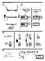
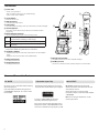
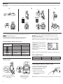
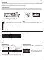
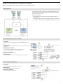
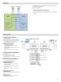
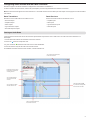
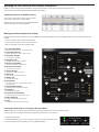
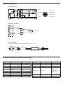
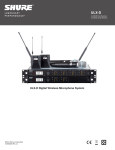
ULX-D ULXD4D Dual Receiver ULXD4Q Quad Receiver ULX-D Digital Wireless Microphone System ©2012 Shure Incorporated 27A20228 (Rev. 1) General Description Shure ULX-D™ Digital Wireless offers uncompromising 24-bit audio quality and RF performance, with intelligent, encryption-enabled hardware, flexible receiver options, and advanced rechargeability options for professional sound reinforcement. A breakthrough in wireless audio quality, Shure digital processing enables ULX-D to deliver the purest reproduction of source material ever available in a wireless system, with a wide selection of trusted Shure microphones to choose from. Extended 20 Hz – 20 kHz frequency range and flat response captures every detail with clarity, presence, and incredibly accurate low end and transient response. With greater than 120 dB, ULX-D delivers wide dynamic range for excellent signal-to-noise performance. Optimized for any input source, ULX-D eliminates the need for transmitter gain adjustments. ULX-D sets a new and unprecedented standard for spectral efficiency and signal stability. The intermodulation performance of ULX-D is an incredible advancement in wireless performance, enabling a dramatic increase in the number of simultaneous active transmitters on one TV channel. Rock-solid RF signal with zero audio artifacts extends over the entire range. For applications where secure wireless transmission is required, ULX-D offers Advanced Encryption Standard (AES) 256-bit encrypted signal for unbreakable privacy. For scalability and modular flexibility, ULX-D receivers come in single, dual, and even quad channel versions. The dual and quad channel receivers offer conveniences such as RF cascade, internal power supply, bodypack frequency diversity, audio output channel summing, and Dante™ digital networking for multi-channel audio over Ethernet. All receivers offer High-Density mode for applications where high channel counts are needed, greatly increasing the amount of simultaneous channels possible over one frequency band. Advanced Lithium-ion rechargeability provides extended transmitter battery life over alkaline batteries, battery life metering in hours and minutes accurate to within 15 minutes, and detailed tracking of battery health status. Generations ahead of any other available system in its class, ULX-D brings a new level of performance to professional sound reinforcement. Features Uncompromising Digital Wireless Audio Scalable, Intelligent Hardware • 24-bit/48 kHz digital audio that delivers incredibly clear and accurate reproduction of the source material • Single (half-rack), Dual and Quad (full-rack) receiver form factors for any size installation • Greater than 120 dB dynamic range through the analog outputs • Ethernet networking for streamlined setup across multiple receivers • 20 Hz – 20 kHz frequency range with flat response • Built-in limiter circuitry prevents digital audio clipping from excessive signal levels. • 130 dB dynamic range (typical) using Dante™ digital networked audio • 60 dB of adjustable system gain easily accessible from the receiver front panel • No transmitter gain adjustments needed - optimized for any input source • Wide selection of trusted Shure Microphones Extremely Efficient and Reliable RF Performance • Up to 72 MHz overall tuning range (region dependent) • Up to 17 active transmitters in one 6 MHz TV channel (22 on an 8 MHz TV channel) • High Density mode enables up to 47 active transmitters in one 6 MHz TV channel (63 in one 8 MHz TV channel), with no audio quality degradation • Rock-solid signal stability with no audio artifacts over the entire 100 meter line-of-sight range using standard supplied ½ wave antennas • Selectable 1, 10, and 20 mW transmitter RF output power • Optimized scanning automatically finds, prioritizes, and selects the cleanest frequencies available • AES 256-bit encryption on all channels • Wireless Workbench® 6 software compatible for advanced frequency coordination, monitoring, and control • AMX/Crestron control • AXT600 Axient™ Spectrum Manager compatibility • Rugged metal housing on both transmitters and receiver • Dual and Quad receivers additionally feature: • RF cascade ports, internal power supply, and dual Ethernet ports • Dante™ digital networked audio over Ethernet • Bodypack Frequency Diversity ensures uninterrupted audio for mission-critical applications • Audio summing routes audio signal to multiple outputs Shure Advanced Power Management • Adapted from industry-leading Axient™ rechargeable technology • Lithium-Ion chemistry and intelligent Shure battery circuitry results in rechargeable batteries with zero memory effect and precision metering • Provides ULX-D transmitters with unmatched 11+ hours of performance time • Transmitters and receivers display remaining battery life in hours and minutes accurate to within 15 minutes • AA backwards compatibility Dual and Quad Receiver Models The ULXD4 receiver is available in dual channel and quad channel models. Both models share the same feature set and functionality, but differ in the number of channels available and the number of audio outputs. The descriptions and procedures in this guide are applicable to either the dual or the quad receiver. 3 Quickstart Instructions 1 2 b a a 45° 150 mA line line line line mic mic mic mic 1-G: 01CH:03 2-G: 01CH:06 3-G: 01CH:08 4-G: 01CH:12 A TxOn TxOn TxOn TxOn sync EXIT control RF audio A B gain OL OL ENTER control SCAN SCAN GROUP SCAN push c 3 SCAN COMPLETE GROUP: 01 OPEN FREQ: 70 RX CHAN FOUND: 4 SCAN EXIT line line mic mic a b on Deploy Completed 4 of 4 Channels Set SYNC TX NOW SCAN CHANNEL SCAN CROUP SCAN 95A15842 c on on ULXD2 ULXD2 ULXD2 on AA SB900 ULXD1 ULXD1 65A15224 4 a control ULXD4Q Digital Wireless Receiver b RX1 RF audio A B OL ENTER OL gain RX2 RF audio A B gain RX3 OL OL RF audio A B gain RX4 OL RX1 RF audio A B gain SCAN OL push OL OL ULXD2 sync on <15 cm (8 in.) ULXD4 Digital Wireless Receiver 4 RF audio A B OL OL EXIT sync gain power on !! ! !! ! mic ! ! ! ! ! !!! !! ! ! ! ! ! ! line mic !! ! line mic Select RX TO SCAN 1 Receiver 2 Receiver 3 Receiver !!! line mic mic push EXIT line mic EXIT power b line gain OL ENTER SCAN sync line RF audio A B OL EXIT Receiver 6 1 ULXD4Q RX1 RF audio A B RX2 gain OL ENTER Digital Wireless Receiver 10 12 8 control SEL RF audio A B RX3 gain OL SEL OL SEL OL RF audio A B RX4 gain OL RF audio A B gain power OL SEL OL OL EXIT sync SCAN IR 3 2 5 4 sync sync sync push 9 7 11 13 14 Front Panel ⑪ RF Signal Strength LEDs ① Infrared (IR) Sync Window Indicate the RF signal strength from the transmitter: Sends IR signal to the transmitter for sync. • Amber = Normal (-90 to -70 dBm) • Red = Overload (greater than -25 dBm) ② Network Icon Illuminates when the receiver is connected with other Shure devices on the network. IP Address must be valid to enable networked control. ⑫ Audio LEDs ③ Encryption Icon Indicate average and peak audio levels: Illuminates when AES-256 encryption is activated. LED Audio Signal Level Red (6) -0.1 dBFS Yellow (5) -6 dBFS Yellow (4) -12 dBFS Use to navigate and select parameter menus. Green (3) -20 dBFS Green (2) -30 dBFS • Push to select a channel or menu item • Turn to scroll through menu items or to edit a parameter value Green (1) -40 dBFS ④ LCD Panel Displays settings and parameters. ⑤ Scan Button Press to find the best channel or group. ⑥ Menu Navigation Buttons ⑦ Control Wheel ⑧ Channel Select Button Description Overload/ limiter Normal peaks Signal Present Note: In Frequency Diversity mode, simultaneous blinking of the red and yellow audio LEDs indicates that diversity audio has been routed to this channel. Press to select a channel. ⑨ Sync Button Press the sync button while the receiver and transmitter IR windows are aligned to transfer settings from the receiver to the transmitter. ⑬ Gain Buttons ⑩ RF Diversity LEDs Press the ▲▼ gain buttons on the front of the receiver to incrementally adjust gain from -18 to +42 dB. Indicate antenna status: ⑭ Power Switch • Blue = normal RF signal between the receiver and transmitter • Red = interference detected • Off = No RF connection between the receiver and transmitter Powers the unit on or off. Note: the receiver will not output audio unless one blue LED is illuminated. B output 4 output 3 output 2 Secondary 1 2 line line line line mic mic mic mic 3 4 5 4 5 6 7 A output 1 Primary 8 9 4 5 4 5 3 2 Back Panel ① AC Power Input IEC Connector, 100 - 240 V AC. ② RF Antenna Diversity Input Jack (2) For antenna A and antenna B. ③ RF Cascade Jack (2) Passes the RF signal from Antenna A and Antenna B to one additional receiver. ④ Mic/Line Switch (one per channel) Applies a 30 dB pad in mic position. ⑤ Balanced XLR Audio Output (one per channel) Connect to a mic or line level input. ⑥ Network Status LED (Green) One per network port. • Off = no link • On = network link • Flashing = network link active ⑦ Ethernet/Dante Network Secondary Port Connect to an Ethernet network to enable remote device control via WWB6 software. Also carries Dante digital audio and control signals for audio distribution, monitoring, and recording - see Dante Network topic. ⑧ Network Speed LED (Amber) One per network port. • Off = 10/100 Mbps • On = 1 Gbps ⑨ Ethernet/Dante Network Primary Port Connect to an Ethernet network to enable remote device control via WWB6 software. Also carries Dante digital audio and control signals for audio distribution, monitoring, and recording - see Dante Network topic. 5 Transmitters ① Power LED • Green = unit is powered on • Red = low battery or battery error (see Troubleshooting) • Amber = power switch is disabled ⑪ ② On/Off Switch Powers the unit on or off. ③ SMA Connector ⑫ ①② Connection point for RF antenna. ④ LCD Display: ⑨ View menu screens and settings. Press any control button to activate the backlight. ⑤ Infrared (IR) Port Align with the receiver IR port during an IR Sync for automated transmitter programming. ULXD1 ④ ⑤ ⑥ ⑥ Menu Navigation Buttons Use to navigate through parameter menus and change values. exit Acts as a 'back' button to return to previous menus or parameters without confirming a value change enter Enters menu screens and confirms parameter changes ▼▲ Use to scroll through menu screens and to change parameter values ⑦ ⑦ Battery Compartment ⑧ Requires Shure SB900 rechargeable battery or 2 AA batteries. ⑧ AA Battery Adapter • Handheld: rotate and store in the battery compartment to use a Shure SB900 battery • Bodypack: remove to accommodate a Shure SB900 battery ⑨ Bodypack Antenna For RF signal transmission. ⑩ Integrated Antenna For RF signal transmission. ③ ④ ⑤ ② ⑥ ULXD2 on ⑦ ⑧ ⑩ ⑪ Microphone Cartridge See Optional Accessories for a list of compatible cartridges. ⑫ TA4M Input Jack Connects to a 4-Pin Mini Connector (TA4F) microphone or instrument cable. Advanced Transmitter Features RF MUTE Use this to turn on a transmitter without interfering with the RF spectrum. Press and hold the exit button during power-on until RF MUTED is displayed. To un-mute, restart the transmitter. Transmitter Input Clip The following warning displays on the receiver LCD panel when the transmitter input is clipped: Tx OVERLOAD To correct, set MIC.OFFSET to 0 dB and if necessary, attenuate the signal source. If the source cannot be attenuated while using a bodypack transmitter, select INPUT PAD from the main menu to attenuate the input signal by 12 dB. 6 MIC.OFFSET MIC.OFFSET compensates for signal level differences between transmitters that share the same receiver channel. Set the offset gain on a low signal level transmitter to match a louder transmitter: UTILITY > MIC.OFFSET Note: For normal gain adjustments, use the receiver gain buttons. Menu Screens 7 8 1 6 1 7 5 6 6dB 2 3 2 4 3 Receiver Channel Transmitter ①Receiver Information ①Transmitter Information ②Gain Setting ②Power Lock Indicator ③Mic. Offset Indicator ③Battery Runtime Indicator Use DEVICE UTILITIES > HOME INFO to change the home screen display. −18 to +42 dB, or Mute. Indicates offset gain is added to the transmitter. ④Transmitter Settings The following information cycles when a transmitter is tuned to the receiver's frequency: • Transmitter Type • Input Pad (Bodypack only) • RF Power Level • Transmitter Lock Status ⑤Battery Runtime Indicator Shure SB900 battery: runtime is displayed in minutes remaining. AA batteries: runtime is displayed with a 5-bar indicator. ⑥TV Channel Displays the TV channel that contains the tuned frequency. ⑦High Density Mode Icon 4 5 Scroll ▲▼ at the home screen to change the display. Indicates power switch is disabled. Shure SB900 battery: runtime is displayed in minutes remaining. AA Batteries: runtime is displayed with a 5-bar indicator. ④Menu Lock Indicator Indicates menu navigation buttons are disabled. ⑤Mic. Offset Displays microphone offset gain value. ⑥RF Power Displays RF power setting or High Density mode icon (if enabled). ⑦Bodypack Input Pad The input signal is attenuated 12 dB. ⑧Encryption Icon Indicates encryption is enabled on the receiver and has been transferred to the transmitter from a sync. Displayed when High Density mode is enabled. Transmitter Setting Icons Display Icon Transmitter Setting Bodypack input is attenuated 12 dB Offset gain is added to the transmitter Lo 1 mW RF power level Nm 10 mW RF power level Hi 20 mW RF power level M Menu is locked P Power is locked -No Tx- No RF connection between a receiver and transmitter or transmitter OFF Receiver Home Screen The home screen displays the following information for each receiver channel: • Group and Channel • Transmitter Status: NoTx or TxOn, battery icon/remaining battery life Press the SEL button to access a channel menu screen. 1 G:01 2 G:01 3 G:01 4 G:01 CH:01 CH:02 CH:03 CH:04 TxOn TxOn >11 TxOn TxOn Home Screen Display Options Receiver Transmitter The HOME INFO menu provides options to change the information shown on the receiver home screen: Home Screen: Press the ▲▼ arrows at the home menu to display one of the following screens: DEVICE UTILITIES > HOME INFO Use the control wheel to select one of the following screen displays. 6dB 7 push control RF audio A B gain power OL ULXD4 OL ENTER Digital Wireless Receiver EXIT sync SCAN push Batteries The transmitter runs on two AA batteries or the Shure SB900 rechargeable battery. Use the included AA battery adapter when using batteries other than the Shure SB900. 3 a b on c 95A15842 on on ULXD2 ULXD2 ULXD2 on on AA SB900 ULXD1 ULXD1 65A15224 4 AA Batteries Shure SB900 Rechargeable Battery a b A 5-segment icon on the receiver and transmitter menu screens indicates battery charge. When using an SB900 rechargeable battery, the receiver and transmitter home screens display the number of hours and minutes remaining. For accurate battery runtime monitoring, set the transmitter to the appropriate battery type: UTILITY > BATTERY > SET.AA.TYPE. !! ! ! ! ! ! on sync RF Power Setting Battery Indicator !!! AA Alkaline Battery Runtime Chart (h:mm) ! ! ! ! ! !! Detailed information for the SB900 is displayed in the receiver BATTERY control RF audio gain power INFO menu and the transmitter menu: UTILITY > BATTERY > BATT. STATS !!! ! ULXD2 sync 8 in cm ( 5 1 < 1/10 mW 20 mW 11:00 to 9:35 5:30 to 4:55 9:35 to 7:15 4:55 to 4:00 7:15 to 4:45 4:00 to 2:30 4:45 to 2:25 2:30 to 1:45 2:25 to 00:45 1:45 to 0:25 00:45 to 00:20 00:25 to 00:10 AA Battery Adapter .) ULXD4 control ENTER EXIT RF audio gain power ENTER EXIT Digital Wireless Receiver SCAN HEALTH : Displays battery sync SCANhealth as a push push percentage of the charge capacity of a new battery. CHARGE: Percentage of a full charge sync CYCLES: Number of times the battery has been charged TEMP: Battery temperature in Celsius and Fahrenheit Note: For additional rechargeable battery information, visit www.shure.com. Shure SB900 Runtime 1 mW 10 mW 20 mW >11 hours >11 hours >7 hour on Installing the Battery Contact Cover Install the included battery contact cover (65A15947) on the handheld transmitter to prevent light reflection in broadcast and performance situations. 1.Align the cover as shown. 2.Slide the cover over the battery contacts until it is flush with the transmitter body. Handheld: Rotate and store the adapter in battery door when using Shure SB900 8 Bodypack: Remove the adapter when using the Shure SB900 Note: Slide the cover off before inserting the transmitter in the battery charger. Setting Gain Adjust gain at the receiver so that the average signal levels are solid green and yellow with peaks that occasionally trigger the red overload LED. Attenuate the gain if the signal overloads repeatedly. Set the XLR output to line-level when possible to optimize sound system noise performance. System Gain Control The gain control on the receiver sets the audio signal level for the entire system. This allows adjustments to be made during a live performance. It is not necessary to change the gain on the transmitter (mic offset) to optimize the gain structure. Any required changes to gain should be made from the receiver. Adjusting Gain control Large Gain Adjustments RF audio A B gain OL ULXD4Q OL ENTER Digital Wireless Receiver RF audio AB power gain power RF audio A B OL gain OL L OL control ULXD4 Digital Wireless Receiver or EXIT IR SCAN sync push Press and hold a gain button Press the ▲▼ gain buttons on the front of the receiver to incrementally adjust gain from -18 to +42 dB. Reading the Audio Meter RF audio A B OL OL Audio peaks illuminate the LEDs for 1 second hold time. The RMS signal is displayed in real time. gain power OL (Overload) LED: Illuminates red when the internal limiter is OL ENTER EXIT SCAN push Use the control wheel in the AUDIO menu Mute To mute the audio, use Shure Wireless Workbench® software or a thirdparty control device. engaged, preventing digital clipping. Receiver Output Level The following table describes the typical total system gain from the audio input to the receiver outputs: Output Jack System Gain (gain control = 0dB) XLR (line setting) +24 dB XLR (mic setting) -6 dB* *This setting matches a typical wired SM58 audio signal level. RF Transmitter RF Power Interference Detection Reference the following table for setting RF Power: Interference Detection monitors the RF environment for potential sources of interference which can cause audio dropouts. RF Power Setting System Range Application 1 mW 33 m (100 ft.) For increased channel reuse at close distances 10 mW 100 m (330 ft.) Typical setups 20 mW >100 m (330 ft.) For hostile RF environments or long-distance applications When interference is identified, the RF LEDs illuminate red and the following warning displays on the receiver LCD panel. If the warning display persists or the audio drops out repeatedly, perform a Scan and Sync at the first opportunity to find a clear frequency. Note: Using the 20 mW setting decreases the transmitter battery runtime and reduces the number of compatible systems. 9 Scan and Sync Use this procedure to tune a receiver and transmitter to the best open channel. 1 control ULXD4Q Important! Before you begin: RX1 ENTER Digital Wireless Receiver RF audio A B RX2 gain RF audio A B OL SEL RX3 gain RF audio A B OL OL OL OL OL EXIT SCAN Turn off all transmitters for the systems you are setting up. (This prevents them from interfering with the frequency scan.) push Turn on the following potential sources of interference so they are operating as they would be during the presentation or performance (the scan will detect and avoid any interference they generate). • Other wireless systems or devices • Computers • CD players 2 • Large LED panels Channel Scan Group Scan • Effects processors 3 EXIT EXIT Group Scan SCAN SCAN SCANNING 1.Press the SEL button to select a channel. 2.Perform a channel scan on the receiver: SCAN > GROUP SCAN. 4 5 ULXD2 SCAN COMPLETE !! ! 6.Press the sync button on the receiver. ! ! ! ! ! !!! !! ! ! ! ! ! ! 5.Power on the ULXD transmitter. !! ! G:01 CH:21 485.775 MHz Rssi: -118 dBm ULXD2 !!! 4.After the scan completes, the receiver displays the group with the most available frequencies. Press the flashing ENTER button to deploy frequencies to each receiver channel. on on !! ! 3.Press SCAN to start the scan. SCANNING appears on the LCD during the scan. 7.Align the IR windows until the receiver IR port illuminates red. 8.When complete, SYNC SUCCESS! appears. The transmitter and receiver are now tuned to the same frequency. Manual Frequency Selection To manually adjust group, channel, or frequency: 6 RX1 RF audio A B 7 gain OL OL control ULXD4Q RX1 RF audio A B OL ENTER Digital Wireless Receiver OL gain RX2 RF audio A B OL OL gain RX3 RF audio A B OL OL gain RX4 RF audio A B gain power OL OL EXIT SCAN sync 1.Press SEL to choose a receiver channel and navigate to the RADIO menu. ULXD2 on push <15 cm (8 in.) 2.Use the control wheel to adjust the group, channel, or frequency. 3.Press ENTER to save changes. Multiple System Setup A setup using networked receivers is the fastest and easiest way to distribute the best open channel to each system. See Networking ULX-D Receivers for networking details. Note: Networked receivers must all be within the same frequency band. Networked Receivers Non-networked Receivers 1.Turn on all receivers. 1.Turn on all receivers. 2.Conduct a group scan on the first receiver to find available frequencies in each group: SCAN > GROUP SCAN. 2.Conduct a group scan on the first receiver to find available frequencies in each group: SCAN > SCAN > GROUP SCAN > SCAN 3.Press ENTER to accept the group number and automatically assign the next best channel to each receiver on the network. The receiver LEDs will flash when a frequency has been assigned. 3.When the scan is complete, use the control wheel to scroll through each group. Press ENTER to select a group that has enough available frequencies for all channels in the system. 4.Turn on a transmitter and sync to the receiver. 4.Sync a transmitter to each receiver channel. Important! Leave the transmitter on and repeat this step for each additional system. Important! Leave all transmitters on use the following steps to set up additional receiver channels: 1.Set each additional receiver channel to the same group as the first receiver: RADIO > G: 2.Conduct a channel scan to find available frequencies within the group: SCAN > SCAN > CHANNEL SCAN > SCAN 3.When the scan is complete, press ENTER to assign frequencies to each receiver channel. 10 4.Sync a transmitter to each receiver channel. High Density Mode High Density mode creates additional bandwidth for more channels in crowded RF environments. Frequency efficiency is optimized by running at 1 mW RF transmit power and narrowing the modulation bandwidth, allowing for the channel spacing to be reduced from 350 kHz to 125 kHz. Transmitters can be positioned on adjacent channels with unsubstantial intermodulation distortion (IMD). High Density mode is ideal for applications where many channels are needed in a confined area, transmission distances are short, and the number of available frequencies is limited. Up to 30 meters of range is available in High Density mode. Setting the Receiver to High Density Mode Frequency Diversity Frequency Diversity is an advanced ULX-D receiver feature that safeguards against loss of audio signal caused by RF interference or by power loss in a transmitter. In Frequency Diversity mode, the signals from two transmitters from a common audio source are routed to the outputs of 2 receiver channels. In the event of interference or power loss, the audio from the good channel is switched to both outputs to preserve the audio signal. Switching between channels is seamless and inaudible. When the receiver senses that the signal quality has improved, audio routing is restored without interrupting the audio signal. Note: WWB6 software offers an option to selectively lock the diversity audio source to a specific transmitter (see Wireless Workbench 6 section). To set the receiver to High Density mode: DEVICE UTILITIES > ADVANCED RF > HIGH DENSITY Best Practices for Frequency Diversity Use the control wheel to set HIGH DENSITY to ON. When prompted, sync the transmitter and receiver to enable HIGH DENSITY mode. Note: When the receiver is in HIGH DENSITY mode, the following indicators are shown on the receiver display: • The HD icon will appear on the receiver display • The receiver band name will be shown with an "HD" added. (example: The G50 band will appear as G50HD) • The transmitter group and channel are assigned letters instead of numbers (example: G:AA CH:AA) • Use the same microphone type and model for each transmitter • Place microphones within close proximity to the source • Use the gain controls to match the output levels for each receiver channel • If Audio Summing is active, use a Y-cable (Shure AXT652) to connect the bodypacks to a single audio source to prevent comb filtering Choosing Diversity Output Routing The following receiver channel routing output options are available: • 1 + 2 • 3 + 4 (quad only) • 1 + 2 / 3 + 4 (quad only) Best Practices for High Density Mode • When band planning, position ULX-D High Density channels in a range of frequencies separated from other devices. • Use a separate RF zone for ULX-D High Density channels to prevent intermodulation distortion from other devices. • During High Density channel scanning, turn on all other transmitters and move them to their intended position. • Perform a walk test to verify transmitter range • If using custom groups, the groups loaded into the receiver must be compatible with High Density mode To enable Frequency Diversity and select a routing option: DEVICE UTILITIES > FREQ DIVERSITY Use the control wheel to choose a routing option, and then press ENTER. Note: Choose OFF to disable Frequency Diversity. Frequency Diversity and Encryption Enabling Encryption while in Frequency Diversity mode provides an additional layer of protection by only passing audio from the most recently synced encrypted transmitter for each receiver channel. Audio Summing Audio summing allows the dual and quad receivers to function as a 2 or 4 channel mixer, respectively. All XLR outputs of the selected channels provide the summed audio. For example, when 1 + 2 is selected (see diagram), the XLR outputs of channels 1 and 2 supply the summed audio of the two channels. Choosing an Audio Summing Mode The following Audio Summing mode options are available: 3+4 1+2 1+2+3+4 1+2/3+4 1 1 +2 1 1 2 1 +2 2 2 3 3 3 4 4 4 1 1+2 2 1+2 3+4 3 3+4 3+4 4 3+4 1 1+2+3+4 2 1+2+3+4 3 1+2+3+4 4 1+2+3+4 To select an Audio Summing mode: Adjusting Gain for Summed Outputs 1.Menu: DEVICE UTILITIES > AUDIO SUMMING Use the gain controls for each channel to create the overall mix balance. The front panel LEDs indicate the audio level for each channel. If an overload occurs, the red LEDs will illuminate indicating that the internal limiter is active and the display will show an overload message. To correct, adjust the overall gain balance. 2.Use the control wheel to select an option, and then press Enter. Note: When set to OFF, Audio Summing is disabled. 11 Firmware Firmware is embedded software in each component that controls functionality. Periodically, new versions of firmware are developed to incorporate additional features and enhancements. To take advantage of design improvements, new versions of the firmware can be uploaded and installed using the Firmware Update Manager tool available in Shure's Wireless Workbench® 6 (WWB6) software. Software is available for download from http://www.shure.com/wwb. Firmware Versioning When updating receiver firmware, update transmitters to the same firmware version to ensure consistent operation. The firmware of all ULX-D devices has the form of MAJOR.MINOR.PATCH (e.g., 1.2.14). At a minimum, all ULX-D devices on the network (including transmitters), must have the same MAJOR and MINOR firmware version numbers (e.g., 1.2.x). Updating the Receiver CAUTION! Ensure that receiver power and network connections are maintained during a firmware update. Do not turn off the receiver until the update is complete. Once the download is complete, the receiver automatically begins the firmware update, which overwrites the existing firmware. 1.From Shure Wireless Workbench software, open the Firmware Update Manager: Tools > Firmware Update Manager. 2.Click Check Now to view new versions available for download. 3.Select the updates and click download. 4.Connect the receiver and computer to the same network. 5.Download the latest firmware to the receiver. Updating the Transmitter 1.To upload the firmware to the transmitter, go to DEVICE UTILITIES > TX FW UPDATE on the receiver. 2.Place the transmitter on its side and align the IR ports. 3.Press ENTER on the receiver to begin the download to the transmitter. IR ports must be aligned for the entire download, which can take 50 seconds or longer. Transmitter Presets Use the TX SYNC SETUP menu to configure transmitter settings on the receiver to transfer to the transmitter during a sync. Each parameter has the default value KEEP, which leaves that setting unaffected by a sync. Creating a System Preset System Presets allow a current receiver setup to be saved and restored. Presets store all receiver settings to provide a quick way to configure a receiver or switch between several different setups. Up to 4 presets can be stored in receiver memory. Feature Setting BP PAD 0 dB, -12 dB To save the current receiver setup as a new preset: DEVICE UTILITIES > SYSTEM RESET > SAVE > CREATE NEW PRESET LOCK Power, Menu, All, None Use the control wheel to name the preset, and then press Enter to save. RF POWER 10mW=Nm, 1mW=Lo, 20mW=Hi To recall a saved preset: DEVICE UTILITIES > SYSTEM RESET > RESTORE BATT Alkaline, NiMH, Lithium Use the control wheel to select the preset name, and then press Enter. BP OFFSET 0 dB to +21 dB (in 3 dB increments) HH OFFSET 0 dB to +21 dB (in 3 dB increments) Cust. Group OFF, ON Note: When Cust. Group is set to ON, it may take up to 30 seconds to complete an IR sync. Select OFF if Custom Groups are not in use for faster IR sync. 12 Locking Controls and Settings Use the LOCK feature to prevent accidental or unauthorized changes to the hardware. Receiver Custom Groups Use this feature to create and export up to 6 groups of manually selected frequencies to networked receivers prior to a group scan to simplify system set up. Menu path: DEVICE UTILITIES > LOCK Tip: Use Wireless Workbench or Wireless Frequency Finder to select the best compatible frequencies. See www.shure.com for more information. Use the control wheel to select and lock any of the following receiver functions. To create a custom group: DEVICE UTILITIES > ADVANCED RF > CUSTOM GROUPS > SETUP • MENU: All menu paths are inaccessible Use the control wheel to choose group, channel and frequency values. Press ENTER to save. • POWER: Power switch is disabled Prior to performing a group scan, export a custom group to networked receivers: • GAIN: Gain adjustment is locked • SCN/SYC: Cannot perform a Scan and Sync Tip: To unlock, press the EXIT button, turn the control wheel to select UNLOCKED, and then press ENTER to save. Transmitter Menu path: UTILITY > LOCK Use the transmitter controls to select and lock any of the following transmitter functions. • MENU LOCK: All menu paths are inaccessible. • POWER LOCK: Power switch is disabled Quick-Lock Option: To turn on the transmitter with its power and menu navigation buttons locked, press and hold the ▲ button during power-on until the locked message is displayed. Tip: To unlock the MENU LOCK, press the ENTER button 4 times to pass through the following screens: UTILITY > LOCK > MENU UNLOCK 1.Go to DEVICE UTILITIES > ADVANCED RF > CUSTOM GROUPS > EXPORT 2.Press the flashing ENTER button to export all custom groups to all receivers on the network. Note: Use the CLEAR ALL option to remove all custom group settings. System Reset System Reset clears the current receiver settings and restores the factory default settings. To restore factory default settings: 1.Go to DEVICE UTILITIES > SYSTEM RESET > RESTORE. 2.Scroll to the DEFAULT SETTINGS option and press ENTER. 3.Press the flashing ENTER button to return the receiver to the default settings. To unlock the POWER LOCK, set the power switch to the off position, then press and hold the ▲ button while resetting the power switch to the on position. RF Cascade Ports Encryption ULX-D features Advanced Encryption Standard (AES-256) to ensure that only the receiver that is keyed to the transmitter can monitor the audio content. The receiver has 2 RF cascade ports on the rear panel to share the signal from the antennas with 1 additional receiver. Use a shielded coaxial cable to connect the RF cascade ports from the first receiver to the antenna inputs of the second receiver. Important! The frequency band must be the same for both receivers. Note: When enabled, encryption is applied to all receiver channels. Encryption does not affect Dante audio signals, audio quality, or channel spacing. 1.Enable encryption on the receiver: DEVICE UTILITIES > ENCRYPTION. The encryption symbol illuminates and the LCD displays SYNC NOW FOR ENCRYPTION. 2.Sync the transmitter to the receiver. The encryption symbol displays on the transmitter. Note: Any change to the encryption status on the receiver such as enabling/ disabling encryption or requesting a new encryption key, requires a sync to send the settings to the transmitter. ENCRYPTION MISMATCH warning will display on the receiver LCD panel if the transmitter and receiver do not share the same encryption key. Antenna Bias Antenna ports A and B provide a DC bias to power active antennas. Set the DC power to off when using passive (non-powered) antennas. To turn bias off: DEVICE UTILITIES > ADVANCED RF > ANTENNA BIAS > OFF 13 Receiver Menu Descriptions Channel Home Screen RADIO Displays Group, Channel, Frequency, and TV information. Use the control wheel to edit values RADIO G: CH: FREQUENCY TV AUDIO GAIN EDIT NAME G: Group for the selected frequency CH: Channel for the selected frequency FREQUENCY Selected frequency (MHz) TV: Displays the TV channel for the selected frequency AUDIO TX SYNC SETUP BP PAD LOCK RF POWER BATT GAIN Use the control wheel or gain buttons to adjust the channel gain from -18 to 42 dB, in 1 dB increments. EDIT NAME Use the control wheel to assign and edit the selected receiver channel name. BP OFFSET HH OFFSET Cust. Group BATTERY INFO HEALTH CHARGE CYCLES TEMP DEVICE ULTILITES FREQUENCY DIVERSITY AUDIO SUMMING ENCRYPTION ADVANCED RF LOCK HOME INFO DISPLAY NETWORK TX FW UPDATE 14 TX SYNC SETUP BP PAD Sets the audio input attenuation options: KEEP, 0, -12. LOCK Sets the lock options: KEEP, Power, Menu, All, None RF POWER Sets the transmitter RF power level: KEEP, 10mW=Nm, 1mW=Lo, 20mW=Hi. BATT Sets the transmitter battery type to ensure accurate metering: KEEP, Alkaline, NiMH, Lithium BP OFFSET Adjustable gain to compensate for signal level difference between transmitters: KEEP, 0 to 21 dB in 3 dB increments HH OFFSET Adjustable gain to compensate for signal level difference between transmitters: KEEP, 0 to 21 dB in 3 dB increments Cust. Group Create Custom Groups of up to 6 frequencies and export to networked receivers BATTERY INFO HEALTH Percentage of charge capacity compared to a new battery CHARGE Percentage of charge capacity SYSTEM RESET CYCLES Number of charge cycles logged by the battery VERSION TEMP Battery temperature: °C/°F DEVICE UTILITIES FREQ DIVERSITY • OFF (default) • 1 + 2 • 3 + 4 (quad only) • 1 + 2 / 3 + 4 (quad only) AUDIO SUMMING • OFF (default) • 1 + 2 • 3 + 4 (quad only) • 1 + 2 / 3 + 4 (quad only) • 1 + 2 + 3 + 4 (quad only) ENCRYPTION Set encryption: ON/OFF ADVANCED RF • HIGH DENSITY: ON/OFF • CUSTOM GROUPS: SETUP/EXPORT/CLEAR • ANTENNA BIAS: ON/OFF • SWITCH BAND (Japan AB band only) LOCK • MENU: LOCKED/UNLOCKED • GAIN: LOCKED/UNLOCKED • POWER: LOCKED/UNLOCKED • SCN/SYC: LOCKED/UNLOCKED HOME INFO Select screen options for Home Menu. DISPLAY • CONTRAST • BRIGHTNESS: LOW/MEDIUM/HIGH NETWORK • CONFIGURATION: SWITCHED/REDUNDANT AUDIO/SPLIT • SHURE CONTROL: DEVICE ID, Network Mode, Set IP and Subnet values for Ethernet network • DANTE: DANTE DEVICE ID, AUDIO & CNTRL, REDUNDANT AUDIO, Set IP and Subnet values for Dante™ network Note: Additional information can be accessed from the selected networking option. TX FW UPDATE IR DOWNLOAD, Tx Firmware Version SYSTEM RESET • RESTORE: Default Settings, Presets • SAVE: Create New Preset • DELETE: Delete Preset VERSION • Model • Band • S/N (serial number) • Ver • Mcu • FPGA • Boot Networking ULX-D Receivers ULX-D Dual and Quad receivers feature a Dante dual-port network interface. Dante technology provides an integrated solution to distribute digital audio, manage control signals, and carry Shure Control (WWB and AMX/Crestron) signals. Dante uses standard IP over Ethernet and safely coexists on the same network as IT and control data. Selectable Dante networking modes route port signals for flexible network set up. Network Control Software The ULX-D receivers can be controlled by Shure Control (WWB6) for remote management and monitoring and the Dante Controller to manage digital audio routing. Signals for AMX and Crestron controllers are carried on the same network as Shure Control. Shure Control Dante Wireless Workbench 6 (WWB6) software provides comprehensive control for wireless audio systems. Wireless Workbench enables live remote adjustments to networked receivers for real-time changes to gain, frequency, RF power, and control locks. A familiar channel strip interface displays audio meters, transmitter parameters, frequency settings and network status. The Dante controller is a free software program created by Audinate™ to configure and manage a network of Dante enabled devices. Use the controller to create audio routes between networked components and to monitor the status of online devices. Visit www.audinate.com for download and installation instructions. Wireless Workbench 6 is available for Windows or Mac and can be downloaded at: www.shure.com/wwb IP Address Configuration An IP address must be assigned to each device in the network to ensure communication and control between components. Valid IP addresses can assigned automatically using a DHCP server or manually from a list of valid IP addresses. If using Dante audio, a separate Dante IP address must also be assigned to the receiver. Automatic IP Addressing Manual IP Addressing 1.If using a DHCP capable Ethernet switch, set the DHCP switch to ON. 1.Connect the receivers to an Ethernet switch. 2.Set the IP Mode to Automatic for all receivers: DEVICE UTILITIES > NETWORK > SHURE CONTROL > NETWORK 2.Set the IP Mode to Manual for all devices: DEVICE UTILITIES > NETWORK > SHURE CONTROL > NETWORK 3.Use the control wheel to set the mode to Automatic, press ENTER to save. 3.Use the control wheel to set the mode to Manual. Note: Use only one DHCP server per network. 4.Set valid IP addresses and subnet values for all devices, press ENTER to save. ON OFF DHCP Dante IP Addressing IP addresses for a Dante network can assigned automatically using a DHCP server or manually from a list of valid IP addresses control ULXD4 Digital Wireless Receiver RX1 RF audio A B gain RX2 RF audio A B gain RX3 OL OL ENTER OL RF audio A B gain RX4 OL RF audio A B gain power gain power gain power OL OL OL OL EXIT SCAN push control ULXD4 Digital Wireless Receiver RX1 RF audio A B gain RX2 RF audio A B gain RX3 OL OL ENTER OL RF audio A B gain RX4 OL RF audio A B OL OL OL OL EXIT SCAN push control ULXD4 Digital Wireless Receiver RX1 RF audio A B OL ENTER OL gain RX2 RF audio A B OL OL gain RX3 RF audio A B OL OL gain RX4 RF audio A B To select the Dante IP addressing mode (Automatic or Manual): DEVICE UTILITIES > NETWORK > DANTE > AUDIO & CNTRL Use the control wheel to select the mode, and then press ENTER to save. OL OL EXIT SCAN push Networking Acronyms DHCP: Dynamic Host Configuration Protocol LAN: Local Area Network MCU: Micro Controller Unit RJ45: Ethernet Connection RX: Receiver TX: Transmitter WWB6: Wireless Workbench 6 Software VLAN: Virtual Local Area Network MAC: Machine Access Code 15 Overview of Dante Network Modes The Dante network interface has two ports (Primary and Secondary) to provide flexible routing and configuration options for network signals. Three selectable Dante network modes are available to control signal routing from the receiver ports to the Dante network. Network Mode Port Function and Signals Secondary Primary SWITCHED Shure Control Dante Audio and Control Shure Control Dante Audio and Control REDUNDANT AUDIO Dante Redundant Audio Shure Control Dante Audio and Control SPLIT Dante Audio and Control Shure Control Application For single network Installations of star or daisy-chained networks. Primary and Secondary ports are configured are 2 separate networks. The Secondary port carries a backup copy of the Primary digital audio signal. Primary and Secondary ports are configured are 2 separate networks to provide isolation between control signals and audio signals. Setting the Dante Networking Mode Select a Dante mode to configure network signal routing on the Primary and Secondary ports. Set all receivers on the network to the same mode. Note: Remove network connections from the receiver before changing the mode. 1.From the receiver menu: DEVICE UTILITIES > NETWORK > CONFIGURATION 2.Use the control wheel to select a mode (SWITCHED, REDUNDANT AUDIO, SPLIT) 3.Press ENTER to save. 4.Cycle receiver power to enable the mode change. 16 CONFIGURATION SWITCHED (default) Network Connection and Configuration Examples Note: Use shielded Cat5e cable for network connections to ensure reliable performance. Switched Mode Switched mode is typically used for single network installations of star or daisy-chained networks. Switched mode is recommended for installations that don't require Dante audio. Network Characteristics: • Dante Audio and Shure Control are present on both the Primary and Secondary ports • The Dante IP address and the Shure Control IP address must be on the same subnet. The computer running WWB6 must also be on this subnet. Network Example (Dante Audio + WWB6) ① Computer Connect the computer running the Dante controller and WWB6 to the Primary port. ① ② DHCP Server ② Can be configured with or without a DHCP server. Do not route audio through the server. ③ Gigabit Ethernet Switch • Do not connect both network ports to the same Ethernet switch • Use a star network topology to minimize audio latency ④ Receiver Connection Note: Dante controller (AXT620, Wi-Fi router, etc...) ③ does not support Wi-Fi network connections. Connect receivers to the Primary port ⑤ Dante Receiver Connect Dante receivers (mixers, recorders, amplifiers) to the Primary port. (mixers, recorders, amplifiers, etc...) ④ ⑤ Network Example (WWB6 Only) ① Computer Connect the computer running WWB6 to the Primary port. ② DHCP Server ① Can be configured with or without a DHCP server. ③ Receiver Connection ② (AXT620, Wi-Fi router, etc...) Connect receivers to the Primary port ③ 17 Redundant Audio Mode Use Redundant mode to carry a backup copy of the Dante audio on the Secondary network in case the audio on the primary network is interrupted. Network Characteristics: • Dante Primary Audio and Shure Control are present on the Primary port • Backup Dante audio is present on the Secondary port • The Primary Dante IP address and the Shure Control IP address must be on the same subnet. The computer running WWB6 must also be on this subnet. • The Secondary Dante IP Address must be set to a different subnet Note: Devices connected to the Redundant network must be compatible with Redundant audio. Network Example ① Computer Connect the computer running the Dante controller and WWB6 to the Primary port. ② DHCP Server ① Can be configured with or without a DHCP server. Do not route audio through the server. ③ Gigabit Ethernet Switches • Use dedicated switches for the Primary and Secondary networks • Do not connect both network ports to the same Ethernet switch • Use a star network topology to minimize audio latency ④ Receiver Connection Connect Primary and Secondary ports to dedicated switches. ② Note: Dante controller does not support Wi-Fi network connections. ③ ④ Note: The Secondary port only supports manual IP or automatic Link-Local configuration. The Link-Local Dante Secondary address subnet is preset to 172.31.x.x (255.255.0.0) ⑤ Dante Receiver Connect Dante receivers (mixers, recorders, amplifiers) to the Primary or Secondary ports. (mixers, recorders, amplifiers, etc...) 18 (AXT620, Wi-Fi router, etc...) ⑤ ③ Split Mode Use Split Mode to isolate control signals from audio signals by placing them on two separate networks. Network Characteristics: • Shure Control is present on the Primary port • Dante Audio is present on the Secondary port • The IP addresses for Dante and Shure Control must be on different subnets Network Example ① Computer (Dante Controller) Connect the computer running the Dante controller to the Secondary port. ② DHCP Server (Secondary Network) Can be configured with or without a DHCP server. Do not route audio through the server. ③ Gigabit Ethernet Switch (Secondary Network) • Use dedicated switches for the Primary and Secondary networks • Do not connect both network ports to the same Ethernet switch • Use a star network topology to minimize audio latency Note: Dante controller does not support Wi-Fi network connections. ① ② (AXT620, Wi-Fi router, etc...) ③ (AXT620, Wi-Fi router, etc...) ⑧ ④ ④ Receiver Connections (Dante Audio) Connect the Secondary ports to the Secondary network switch. ⑤ ⑥ ⑦ ⑤ Computer (Shure Control) Connect the computer running the Shure Control to the Primary port. ⑥ DHCP Server (Primary Network) Can be configured with or without a DHCP server. Do not route audio through the server. ⑦ Gigabit Ethernet Switch (Primary Network) • Use dedicated switches for the Primary and Secondary networks • Do not connect both network ports to the same Ethernet switch • Use a star network topology to minimize audio latency (mixers, recorders, amplifiers, etc...) ⑨ ⑧ Receiver Connections (Shure Control) Connect the Primary ports to the Primary network switch. ⑨ Dante Receiver Connect Dante receivers (mixers, recorders, amplifiers) to the Primary port. 19 Assigning Network Device IDs for Shure Control and Dante Control When using the receiver in a network with Shure Control (WWB6) and a Dante Controller, two Device IDs are required: one for Shure Control and one for Dante Control. Device IDs are used to identify devices on the network and for creating Dante digital audio routes. Best Practices Using the following best practices will help to organize network setup and ease troubleshooting. • For consistency, convenience, and easy troubleshooting, use the same device ID for both WWB6 (Shure Control) and for the Dante network. • The Dante network requires unique Dante device IDs to prevent a loss of audio signal routing. Any duplicate IDs on the network will be tagged with a number such as -1, -2, -3, etc.... and must be changed to a unique value. • WWB6 (Shure Control) does not require unique device IDs and duplicates do not affect the Dante network; however, a best practice is to use unique device IDs. Setting the Shure Control Device ID Viewing Dante Device IDs in the Dante Controller Dante device IDs are displayed in the Network View window in the Dante Controller. 1.Launch WWB6. 2.Open the Inventory View. 1.Launch the Dante controller and open the Network View window. 2.Verify that the Dante device IDs match the IDs entered in the receiver. 3.Click on the Device ID to enable editing. Tip: Click on the device icon next to the channel name to identify the receiver using the Flash function. Optionally, the Shure Control Device ID can be entered from the receiver front panel: 1.From the receiver menu: DEVICE UTILITIES > NETWORK > SHURE CONTROL > Dev. ID 2.Use the control wheel to edit the ID. 3.Press ENTER to save. Setting the Dante Device ID The Dante ID can be set from the ULXD receiver menu or from the Dante controller. Note: Changing the Dante ID will cause a loss of audio signal. After an ID has been changed, use the Dante controller to restore audio route subscriptions using the new ID. From the receiver menu: 1.DEVICE UTILITIES > NETWORK > DANTE > Dev. ID DANTE DEVICE ID ULXD-RX1 2.Use the control wheel to enter a unique ID. 3.Press ENTER to save. From the Dante controller: 1.Open the Device View and select the receiver from the pulldown menu. 2.Click on the Device Config tab. 3.Enter the ID in the Rename Device box and press ENTER. 20 Identify Device Feature The Dante controller's Identify Device feature flashes the front panel LEDs of a selected receiver to provide identification when multiple receivers are in use. Open the Device View in the Dante controller and click on the identify icon (eye). The front panel LEDs of the selected receiver will respond by flashing. Configuring Audio Routes with the Dante Controller Devices that appear in the Dante controller are categorized as "Transmitters" and "Receivers" In order for audio to flow in the network, audio routes (subscriptions) must be configured between transmitters and receivers. Note: ULX-D receivers will appear in the Dante controller as a Transmitter. Devices that have both inputs and outputs commonly appear as both transmitters and receivers. Dante Transmitters Dante Receivers Devices that send or add audio into the network such as: Devices that receive audio from the network such as: • Receiver Outputs • Amplifier Inputs • Mixer Outputs • Signal Processor Inputs • Amplifier Outputs • Mixer Inputs • Signal Processor Outputs • Recorder Inputs • Recorder Playback Outputs Forming an Audio Route Launch the Dante Controller and click on the intersection point between components to form an audio route. The audio route is also referred to as a Subscription. 1.Find the intersection between the transmitter and receiver channels. 2.Click on the + where the components meet. 3.A green checkmark indicates that the audio route has been established. 4.Check the audio to verify that the audio route has been formed. For additional information about the Dante controller, visit www.audinate.com. Click to expand this Dante device to view its Tx channels Enter text to show only those Dante devices and channels containing that text Click to expand all Dante devices and view all Rx channels Click while holding the Ctrl key to subscribe to all possible channels at the same time. Click to collapse the Dante device Rx channel view Click to expand all Dante device and view all Tx channels 21 Restoring Dante Factory Settings The receiver and the Dante network card can be reset to restore factory Dante settings. Performing a reset is helpful for clearing existing data before setting up a system. Caution! Performing a reset on either the Dante network card or on the ULX-D receiver will interrupt the Dante audio. Tip: Prior to performing a factory reset, note the current Dante network mode and IP settings. After a reset, the Dante network mode reverts to SWITCHED, and the IP address mode revert to AUTO. Restoring Receiver and Dante Card Factory Settings Restoring the Dante Network Card Factory Settings Performing a reset from the receiver restores the factory settings and configures the Shure Control and Dante IP address mode to AUTO. The Factory Reset option within the Dante controller restores the Dante card to the factory settings and configures the Dante IP address mode to AUTO. 1.From the receiver menu: DEVICE UTILITIES > SYSTEM RESET > RESTORE 1.From the Dante controller, select a receiver and open the Network Config tab. 2.Press ENTER to complete the reset. 2.Click on Factory Reset. DEFAULT SETTINGS RESTORE DEFAULT SETTINGS RESTORE DEFAULTS OVERWRITE CURRENT SETTINGS WITH DEFAULT SETTINGS? 3.Allow the Dante controller to refresh before making any additional changes. Connecting to an AMX or Crestron System The ULX-D receiver connects to an AMX or Crestron control system via the Ethernet, using on the same cables used to carry Shure Control (WWB6). Use only one controller per system to avoid messaging conflicts. • Connection: Ethernet (TCP/IP; ULX-D receiver is the client) • Port: 2202 For a comprehensive list of ULX-D command strings, visit: http://shure.custhelp.com/app/answers/detail/a_id/4976 Network Troubleshooting • Use only one DHCP server per network • All devices must share the same subnet mask • All receivers must have the same level of firmware revision installed • Look for the illuminated network icon on the front panel of each device: If the icon is not illuminated, check the cable connection and the LEDs on the network jack. If the LEDs are not on and the cable is plugged in, replace the cable and recheck the LEDs and network icon. To check connectivity of WWB6 to the network: 1.Start WWB6 software and use Inventory view to see devices connected to the network. 2.If not, find the IP address from one of the devices on the network (such as a ULX-D receiver) and see if you can ping it from the computer running WWB6. 3.From a WINDOWS/MAC command prompt, type ‘ping IPADDRESS’ of the device (e.g. "ping 192.168.1.100"). 4.If the ping returns success (no packet loss), then the computer can see the device on the network. If the ping returns failure (100% packet loss), then check the IP address of the computer to ensure it’s on the same subnet. 5.If the pings are successful and the devices still do not show up in the WWB6 inventory, check to ensure all firewalls are either disabled or allow the WWB network traffic to pass to the application. Check that firewall settings are not blocking network access. 22 Managing the ULXD Receiver with Wireless Workbench 6 Adding a computer running Wireless Workbench® 6 to the network allows for remote control and monitoring of the receiver. Visit: www.shure.com/wwb to download Wireless Workbench 6 software. Viewing the Receiver in WWB6 Inventory Click on the Inventory tab to view the receiver channels. Double-click on parameters to enable editing. Tip: Clicking on the receiver Icon next to the Model flashes the front panel LEDs for remote identification. Managing and Monitoring Receiver Settings Manage and monitor receiver settings by opening the Monitor tab in Wireless Workbench. Click on the Settings button to show or hide the full Properties window. 1.Click on the Monitor tab to view the Device Chooser. 2.From the Device Chooser, click on a channel to select. 3.Click on Properties to open the Properties window. ① RF and Audio Meters Displays: current levels, band, TV, and TX Overload ② Transmitter Settings Displays: RF Power, Tx Type, Tx Offset, Tx Lock ③ Frequency Settings Use drop-down to edit value 1 2 ④ Encryption Icon Illuminates when Encryption is enabled 6 ⑤ Receiver Output Mute Click on the mute button to enable mute 3 ⑥ Receiver Gain Setting Use drop-down to edit value 5 ⑦ Custom Groups Click to enter custom group settings 4 ⑧ IR Presets Click to configure transmitter IR presets 10 ⑨ Utilities Tab Accesses Utility settings ⑩ Network Tab Set network mode, view: IP address, Subnet, MAC, Firmware version 11 7 8 15 9 ⑪ Advanced RF Settings Enable High Density mode or Antenna Bias ⑫ Encryption Enable/Disable Encryption ⑬ Frequency Diversity Mode 12 13 Enable and Select Frequency Diversity mode ⑭ Audio Summing Enable and Select Audio Summing mode 14 ⑮ Locks Lock/Unlock: Menu, Gain, Power, Scan/Sync Locking the Audio Source in Frequency Diversity Mode WWB6 software offers an option to selectively lock the Frequency Diversity audio source to a specific transmitter. Lock the audio source to select the best audio if a problem develops with one of the channels. 1.Open the monitoring tab. 2.Under FD Audio Source, click on "Lock to" option to select a transmitter as the audio source. To restore Frequency Diversity switching, click on the Auto Switch option. 23 Troubleshooting Issue See Solution... No Sound Power, Cables, Radio Frequency, or Encryption Mismatch Faint sound or distortion Gain Lack of range, unwanted noise bursts, or dropouts RF Cannot turn transmitter off or change frequency settings, or can't program receiver Interface locks Encryption Mismatch message Encryption Mismatch Firmware Mismatch message Firmware Mismatch Antenna Fault message RF Power Make sure that the receiver and transmitter are receiving sufficient voltage. Check the battery indicators and replace the transmitter batteries if necessary. Gain Adjust the system gain on the front of the receiver. Ensure the output level (XLR output only) on the back of the receiver corresponds to the input of the mixing console, amplifier, or DSP. Cables Check that all cables and connectors are working correctly. Interface Locks The transmitter and the receiver can be locked to prevent accidental or unauthorized changes. A locked feature or button will produce the Locked screen on the LCD panel. Encryption Mismatch Re-sync all receivers and transmitters after enabling or disabling encryption. Firmware Mismatch Reducing Interference • Perform a group or channel scan to find the best open frequency. Perform a sync to transfer the setting to the transmitter. • For multiple systems, check that all systems are set to channels in the same group (systems in different bands do not need to be set to the same group). • Maintain a line of sight between transmitter and receiver antennas. • Move receiver antennas away from metal objects or other sources of RF interference (such as CD players, computers, digital effects, network switches, network cables and Personal Stereo Monitor (PSM) wireless systems). • Eliminate RF overload (see below). Increasing Range If the transmitter is more than 6 to 60 m (20 to 200 ft) from the receiver antenna, you may be able to increase range by doing one of the following: • Reduce interference (see above). • Increase transmitter RF power level. • Use Normal mode instead of High Density mode. • Use an active directional antenna, antenna distribution system, or other antenna accessory to increase RF range. Eliminating RF Overload If you see the red RF LED on a receiver, try the following: Paired transmitters and receivers must have the same firmware version installed to ensure consistent operation. See Firmware topic for firmware update procedure. • Reduce the transmitter RF power level Radio Frequency (RF) • Use omnidirectional antennas RF LEDs If neither blue RF Diversity LED is illuminated, then the receiver is not detecting the presence of a transmitter. The amber RF Signal Strength LEDs indicate the amount of RF power being received. This signal could be from the transmitter, or it could be from an interfering source, such as a television broadcast. If more than one or two of the amber RF LEDs are still illuminated while the transmitter is off, then that channel has too much interference, and you should try a different channel. The red RF LED indicates RF overload. This will usually not cause a problem unless you are using more than one system at the same time, in which case, it can cause interference in the other system. Compatibility • Perform a Scan and Sync to ensure the transmitter and receiver are set to the same group and channel. • Look at the label on the transmitter and receiver to make sure they are in the same band (G50, J50, L50, etc...). 24 • Move the transmitter further away from the receiver—at least 6 m (20 ft) • If you are using active antennas, reduce antenna or amplifier gain. Antenna Faults The Antenna Fault message indicates a short circuit condition at an antenna port. • Check antennas and cables for damage • Ensure that antenna ports are not overloaded • Check antenna bias voltage setting. Turn off voltage if using passive antennas. ULX-D Specifications RF Carrier Frequency Range 470–932 MHz, varies by region (See Frequency Range and Ouput Power table) Working Range 100 m (330 ft) Note: Actual range depends on RF signal absorption, reflection and interference. RF Tuning Step Size 25 kHz, varies by region Image Rejection >70 dB, typical RF Sensitivity −98 dBm at 10-5 BER Latency <2.9 ms Audio Frequency Response ULXD1 20 – 20 kHz (±1 dB) ULXD2 Note: Dependent on microphone type Audio Dynamic Range A-weighted, typical, System Gain @ +10 XLR Analog Output >120 dB Dante Digital Output 130 dB Total Harmonic Distortion −12 dBFS input, System Gain @ +10 <0.1% System Audio Polarity Positive pressure on microphone diaphragm produces positive voltage on pin 2 (with respect to pin 3 of XLR output) and the tip of the 6.35 mm (1/4inch) output. Operating Temperature Range -18°C (0°F) to 50°C (122°F) Note: Battery characteristics may limit this range. Storage Temperature Range -29°C (-20°F) to 74°C (165°F) Note: Battery characteristics may limit this range. ULXD4D & ULXD4Q Dimensions 44 x 482 x 274 mmH x W x D Weight ULXD4D 3.36 kg (7.4 lbs), without antennas ULXD4Q 3.45 kg (7.6 lbs), without antennas Housing steel; Extruded Aluminum ULXD4 Power Requirements ULXD4D 100 to 240 V AC, 50-60 Hz, 0.26 A max. ULXD4Q 100 to 240 V AC, 50-60 Hz, 0.32 A max. Audio Output Gain Adjustment Range −18 to +42 dB in 1 dB steps (plus Mute setting) Configuration XLR balanced (1=ground, 2=audio +, 3=audio −) Impedance 100 Ω Full Scale Output LINE setting +18 dBV MIC setting −12 dBV RF Input Mic/Line Switch 30 dB pad Spurious Rejection >80 dB, typical Phantom Power Protection Yes Connector Type BNC Impedance 50 Ω Networking Bias Voltage 12 to 13 V DC, 150 mA maximum, per antenna Network Interface Dual Port Ethernet 10/100 Mbps, 1Gbps, Dante Digital Audio switchable on/off Cascade Output Connector Type BNC Network Addressing Capability DHCP or Manual IP address Maximum Cable Length 100 m (328 ft) Note: For connection of one additional receiver in the same band Configuration Unbalanced, passive Impedance 50 Ω Insertion Loss 0 dB 25 ULXD1 ULXD2 MIc Offset Range 0 to 21 dB (in 3 dB steps) Mic Offset Range 0 to 21 dB (in 3 dB steps) Battery Type Shure SB900 Rechargeable Li-Ion or LR6 AA batteries 1.5 V Battery Type Shure SB900 Rechargeable Li-Ion or LR6 AA batteries 1.5 V Battery Runtime @ 10 mW Battery Runtime @ 10 mW Shure SB900 >11 hours Shure SB900 >11 hours alkaline 11 hours alkaline 11 hours See Battery Runtime Chart See Battery Runtime Chart Dimensions 86 mm x 66 mm x 23 mm (3.4 in. x 2.6 in. x 0.9 in.) H x W x D Dimensions 256 mm x 51 mm (10.1 in. x 2.0 in.) L x Dia. Weight 142 g (5.0 oz.), without batteries Weight 340 g (12.0 oz.), without batteries Housing Cast aluminum Housing Machined aluminum Audio Input Audio Input Connector 4-Pin male mini connector (TA4M), See drawing for details Configuration Unbalanced Configuration Unbalanced Maximum Input Level 1 kHz at 1% THD 145 dB SPL (SM58), typical Impedance 1 MΩ, See drawing for details Maximum Input Level 1 kHz at 1% THD Pad Off 8.5 dBV (7.5 Vpp) Pad On 20.5 dBV (30 Vpp) Preamplifier Equivalent Input Noise (EIN) System Gain Setting ≥ +20 -120 dBV, A-weighted, typical RF Output Connector SMA Note: Dependent on microphone type RF Output Antenna Type Integrated Single Band Helical Occupied Bandwidth <200 kHz Modulation Type Shure proprietary digital Power 1 mW, 10 mW, 20 mW See Frequency Range and Ouput Power table, varies by region Antenna Type 1/4 wave Impedance 50 Ω Occupied Bandwidth <200 kHz Modulation Type Shure proprietary digital Power 1 mW, 10 mW, 20 mW See Frequency Range and Ouput Power table, varies by region 26 Battery Runtime Battery Type 1 mW 10 mW 20 mW SB900 >11 hours >11 hours >7 hours Alkaline <11 hours <11 hours <5.5 hours NiMH <11 hours <11 hours <8 hours Li-primary 12.5-18 hours 12.5-18 hours 9.5-12 hours The values in this table are typical of fresh, high quality batteries. Battery runtime varies depending on the manufacturer and age of the battery. Tables and Diagrams TA4M Connector 500 Ω 1µF 910k Ω Z 5 V DC 500 Ω Active Load 100 µF 440 pF Pad 12dB Audio Input ① Ground ② Bias Voltage ③ Audio Input Ground ④ Active Load XLR Receiver Output 50 Ω 22 µF -30 dB 50 Ω 22 µF mic/ line XLR to ¼ Output Use the following wiring diagram to convert the XLR output to a ¼ output. 2 2 3 1 * 1 * No Connection Frequency Range and Transmitter Output Power Band Frequency Range ( MHz) Power (mW) Band Frequency Range ( MHz) Power (mW) G50 470 to 534 1/10/20 P51 710 to 782 1/10/20 G51 470 to 534 1/10/20 R51 800 to 810 1/10/20 G52 479 to 534 1/10 JB (Tx only) 806 to 810 1/10 H51 534 to 598 1/10/20 H52 534 to 565 1/10 J50 572 to 636 1/10/20 K51 606 to 670 1/10 L50 632 to 696 1/10/20 L51 632 to 696 1/10/20 "A" band (770.250805.750): 1/10/20 AB (Rx and Tx) 770 to 810 "B" band (806.125809.750): 1/10 Q51 794 to 806 1/10/20 X50 925 to 932 1/10 27 Furnished Accessories All Systems Bodypack System Receiver ULXD4D (Dual Receiver), ULXD4Q (Quad Receiver) Bodypack Transmitter ULXD1 1/2-Wave Antenna (2) Varies by band (see Antennas table for band-specific part numbers) 1/4-Wave Antenna Varies by band (see Antennas table for band-specific part numbers) Hardware Kit (1) 90XN1371 Zipper Bag 95A2313 2' BNC Cable (2) 95K2035 AA Alkaline batteries (2) 80B8201 BNC Bulkhead Adapters (2) 95A8994 3' Ethernet Cable (1) 95B15103 Handheld Systems Handheld Transmitter ULXD2 Cartridge see options below Microphone Clip 95T9279 Zipper Bag 95B2313 AA Alkaline batteries (2) 80B8201 Battery Contact Cover 65A15947 Choice of one (1) of the following: SM58 RPW112 SM86 RPW114 SM87A RPW116 Beta 58A RPW118 Beta 87A RPW120 Beta 87C RPW122 Choice of one (1) of the following: Instrument cable WA302 Instrument Clip-on microphone Beta 98H/C Lavalier microphone MX150, MX153, WL183, WL184, WL185 Headset microphone WH30TQG Antennas Band 1/2-Wave Receiver Antennas 1/4-Wave Transmitter Antennas G50 95AA9279 95G9043 (Yellow) G51 95AA9279 95G9043 (Yellow) G52 95AA9279 95G9043 (Yellow) H51 95AL9279 95D9043 (Gray) H52 95AL9279 95D9043 (Gray) J50 95AK9279 95E9043 (Black) K51 95AJ9279 95E9043 (Black) L50 95AD9279 95E9043 (Black) L51 95AD9279 95E9043 (Black) P51 95AF9279 95F9043 (Blue) R51 95M9279 95F9043 (Blue) AB 95M9279 N/A Q51 95M9279 N/A X50 95V9279 95H9043 (Red) Optional Accessories Shure Rechargeable Battery SB900 UHF Powered Directional Antenna UA874WB 8-Bay Battery Charger SBC800 Passive Directional Antenna PA805SWB Dual Docking Battery Charger SBC200 Carrying Case WA610 Coaxial Cable, BNC-BNC, RG58C/U type, 50 Ohm, 2 ft length (0.6 m) UA802 Y-Cable for Bodypack Transmitters AXT652 UA806 Active Antenna Spitter UA845SWB Coaxial Cable, BNC-BNC, RG58C/U type, 50 Ohm, 6 ft length (2 m) Passive Antenna Splitter/Combiner Kit UA221 UA825 UHF Line Amplifier UA830WB Coaxial Cable, BNC-BNC, RG8X/U type, 50 Ohm, 25 ft length (7.5 m) UHF Antenna Power Distribution Amplifier (U.S.A.) UA844SWB Coaxial Cable, BNC-BNC, RG8X/U type, 50 Ohm, 50 ft length (15 m) UA850 UHF Antenna Power Distribution Amplifier (Europe) UA844SE Coaxial Cable, BNC-BNC, RG213/U Type, 50 Ohm, 100 ft length (30 m) UA8100 Front Mount Antenna Kit (Includes 2 cables and 2 bulkhead UA600 Remote Antenna Bracket with BNC Bulkhead Adapter UA505 28 Certifications This Class B digital apparatus complies with Canadian ICES-003. Cet appareil numérique de la classe B est conforme à la norme NMB-003 du Canada. ULXD1, ULXD2, ULXD4D, ULXD4Q This product meets the Essential Requirements of all relevant European directives and is eligible for CE marking. Meets requirements of the following standards: EN 300 422 Parts 1 and 2, EN 301 489 Parts 1 and 9. ULXD1, ULXD2 LICENSING INFORMATION Licensing: A ministerial license to operate this equipment may be required in certain areas. Consult your national authority for possible requirements. Changes or modifications not expressly approved by Shure Incorporated could void your authority to operate the equipment. Licensing of Shure wireless microphone equipment is the user’s responsibility, and licensability depends on the user’s classification and application, and on the selected frequency. Shure strongly urges the user to contact the appropriate telecommunications authority concerning proper licensing, and before choosing and ordering frequencies. Information to the user ULXD4D, ULXD4Q This equipment has been tested and found to comply with the limits for a Class B digital device, pursuant to Part 15 of the FCC Rules. These limits are designed to provide reasonable protection against harmful interference in a residential installation. This equipment generates uses and can radiate radio frequency energy and, if not installed and used in accordance with the instructions, may cause harmful interference to radio communications. However, there is no guarantee that interference will not occur in a particular installation. If this equipment does cause harmful interference to radio or television reception, which can be determined by turning the equipment off and on, the user is encouraged to try to correct the interference by one or more of the following measures: Approved under the Declaration of Conformity (DoC) provision of FCC Part 15. • Reorient or relocate the receiving antenna. • Increase the separation between the equipment and the receiver. Certified in Canada by IC to RSS-123. • Connect the equipment to an outlet on a circuit different from that to which the receiver is connected. Certified under FCC Part 74. Certified by IC in Canada under RSS-123 and RSS-102. IC: 616A-ULXD1 G50, 616A-ULXD1 J50, 616A-ULXD1 L50; 616A-ULXD2 G50, 616A-ULXD2 J50, 616A-ULXD2 L50. FCC: DD4ULXD1G50, DD4ULXD1J50, DD4ULXD1L50; DD4ULXD2G50, DD4ULXD2J50, DD4ULXD2L50. IC: 616A-ULXD4D G50, 616A-ULXD4D J50, 616A-ULXD4D L50; 616A-ULXD4Q G50, 616A-ULXD4Q J50, 616A-ULXD4Q L50. Conforms to electrical safety requirements based on IEC 60065. This device complies with Industry Canada licence-exempt RSS standard(s). Operation of this device is subject to the following two conditions: (1) this device may not cause interference, and (2) this device must accept any interference, including interference that may cause undesired operation of the device. Le présent appareil est conforme aux CNR d'Industrie Canada applicables aux appareils radio exempts de licence. L'exploitation est autorisée aux deux conditions suivantes : (1) l'appareil ne doit pas produire de brouillage, et (2) l'utilisateur de l'appareil doit accepter tout brouillage radioélectrique subi, même si le brouillage est susceptible d'en compromettre le fonctionnement. Note: EMC conformance testing is based on the use of supplied and recommended cable types. The use of other cable types may degrade EMC performance. The CE Declaration of Conformity can be obtained from Shure Incorporated or any of its European representatives. For contact information please visit www.shure.com The CE Declaration of Conformity can be obtained from: www.shure.com/ europe/compliance • Consult the dealer or an experienced radio/TV technician for help. WARNING: Danger of explosion if battery incorrectly replaced. Operate only with Shure compatible batteries. Note: Use this receiver only with the included power supply or a Shureapproved equivalent. WARNING • Battery packs may explode or release toxic materials. Risk of fire or burns. Do not open, crush, modify, disassemble, heat above 140°F (60°C), or incinerate • Follow instructions from manufacturer • Never put batteries in mouth. If swallowed, contact your physician or local poison control center • Do not short circuit; may cause burns or catch fire • Do not charge or use battery packs with other than specified Shure products • Dispose of battery packs properly. Check with local vendor for proper disposal of used battery packs • Batteries (battery pack or batteries installed) shall not be exposed to excessive heat such as sunshine, fire or the like Authorized European representative: Shure Europe GmbH Headquarters Europe, Middle East & Africa Department: EMEA Approval Jakob-Dieffenbacher-Str. 12 75031 Eppingen, Germany Phone: 49-7262-92 49 0 Fax: 49-7262-92 49 11 4 Email: [email protected] 29 FREQUENCIES FOR EUROPEAN COUNTRIES ULXD-G51 470 - 534 MHz, max. 20 mW Country Code Code de Pays Codice di paese Código de país Länder-Kürzel A, B, BG, CH, CY, CZ, D, EST F, GB, GR, H, I, IS, L, LT NL, P, PL, S, SK, SLO DK, FIN, M, N Frequency Range Gamme de frequences Gamme di frequenza Gama de frequencias Frequenzbereich 470 - 534 MHz * 470 - 534 MHz * 470 - 534 MHz * * All other countries * HR, E, IRL, LV, RO, TR * ULXD-H51 534 - 598 MHz, max. 20 mW Country Code Code de Pays Codice di paese Código de país Länder-Kürzel A, B, BG, CH, CY, CZ, D, EST F, GB, GR, H, I, IS, L, LT NL, P, PL, S, SK, SLO DK, FIN, M, N Frequency Range Gamme de frequences Gamme di frequenza Gama de frequencias Frequenzbereich 534 - 598 MHz * 534 - 598 MHz * 534 - 598 MHz * * All other countries * HR, E, IRL, LV, RO, TR * ULXD-P51 710 - 782 MHz, max. 20 mW Country Code Code de Pays Codice di paese Código de país Länder-Kürzel A, B, BG, CH, CY, CZ, D, EST, F, GB, GR, H, I, IS, L, LT, NL, P, PL, S, SK, SLO RO DK, E, FIN, HR, IRL, LV, M, N, TR all other countries Frequency Range Gamme de frequences Gamme di frequenza Gama de frequencias Frequenzbereich 710 - 782 MHz * 710 - 782 MHz * “718-719; 726-727; 734-743; 750-751; 758-759 MHz*” * * ULXD-R51 800 - 810 MHz, max. 20 mW Country Code Code de Pays Codice di paese Código de país Länder-Kürzel N A, B, BG, CH, CY, CZ, D, DK, E, EST F, FIN, GB, GR, H, HR, I, IRL, IS, L, LT LV, M, N, NL, P, PL, S, SK, SLO, TR All other countries Frequency Range Gamme de frequences Gamme di frequenza Gama de frequencias Frequenzbereich 800 - 810 MHz* * * * * ULXD-K51 606 - 670 MHz, max. 20 mW Country Code Code de Pays Codice di paese Código de país Länder-Kürzel A, B, BG, CH, CY, CZ, D, EST F, GB, GR, H, I, IS, L, LT NL, P, PL, S, SK, SLO RO Frequency Range Gamme de frequences Gamme di frequenza Gama de frequencias Frequenzbereich 606 - 670 MHz * 606 - 670 MHz * 606 - 670 MHz * 646-647;654-655;662-663 MHz* All other countries * DK, E, FIN, HR, IRL, LV, M, N, TR * * IMPORTANT NOTE: THIS EQUIPMENT MAY BE CAPABLE OF OPERATING ON SOME FREQUENCIES NOT AUTHORIZED IN YOUR REGION. PLEASE CONTACT YOUR NATIONAL AUTHORITY TO OBTAIN INFORMATION ON AUTHORIZED FREQUENCIES AND RF POWER LEVELS FOR WIRELESS MICROPHONE PRODUCTS IN YOUR REGION. A ministerial license may be required to operate this equipment in certain areas. Consult your national authority for possible requirements. * WICHTIG HINWEIS: DIESES GERÄT KANN MÖGLICHERWEISE AUF EINIGEN FREQUENZEN ARBEITEN, DIE IN IHREM GEBIET NICHT ZUGELASSEN SIND. WENDEN SIE SICH BITTE AN DIE ZUSTÄNDIGE BEHÖRDE, UM INFORMATIONEN ÜBER ZUGELASSENE FREQUENZEN UND ERLAUBTE SENDELEISTUNGEN FÜR DRAHTLOSE MIKROFONPRODUKTE IN IHREM GEBIET ZU ERHALTEN. Zulassung: In einigen Gebieten ist für den Betrieb dieses Geräts u.U. eine behördliche Zulassung erforderlich. Wenden Sie sich bitte an die zuständige Behörde, um Informationen über etwaige Anforderungen zu erhalten. *IMPORTANT REMARQUE: IL EST POSSIBLE QUE CE MATÉRIEL SOIT CAPABLE DE FONCTIONNER SUR CERTAINES FRÉQUENCES NON AUTORISÉES LOCALEMENT. SE METTRE EN RAPPORT AVEC LES AUTORITÉS COMPÉTENTES POUR OBTENIR LES INFORMATIONS SUR LES FRÉQUENCES ET NIVEAUX DE PUISSANCE HF AUTORISÉES POUR LES SYSTÈMES DE MICROPHONES SANS FIL LOCALEMENT. Autorisation d’utilisation : Une licence officielle d’utilisation de ce matériel peut être requise dans certains pays. Consulter les autorités compétentes pour les exigences possibles. *IMPORTANTE NOTA: QUESTO APPARECCHIO PUÒ ESSERE IN GRADO DI FUNZIONARE A FREQUENZE NON AUTORIZZATE NELLA REGIONE IN CUI SI TROVA L’UTENTE. RIVOLGERSI ALLE AUTORITÀ COMPETENTI PER OTTENERE LE INFORMAZIONI RELATIVE ALLE FREQUENZE ED AI LIVELLI DI POTENZA RF AUTORIZZATE NELLA PROPRIA REGIONE PER I PRODOTTI MICROFONICI SENZA FILI. Concessione della licenza all’uso: per usare questo apparecchio, in certe aree può essere necessaria una licenza ministeriale. Per i possibili requisiti, rivolgersi alle autorità competenti. *IMPORTANTE NOTA: ES POSIBLE QUE ESTE EQUIPO FUNCIONE EN ALGUNAS FRECUENCIAS NO AUTORIZADAS EN SU REGION. POR FAVOR CONTACTE A LA AUTORIDAD NACIONAL PARA OBTENER INFORMACION ACERCA DE LAS FRECUENCIAS AUTORIZADAS Y LOS NIVELES DE POTENCIA DE RADIOFRECUENCIA PARA PRODUCTOS CON MICROFONOS INALAMBRICOS EN SU ZONA. Licencia de uso: Se puede requerir una licencia ministerial para utilizar este equipo en algunas áreas. Consulte a la autoridad nacional sobre los posibles requisitos. 30 Europe, Middle East, Africa: Shure Europe GmbH Jakob-Dieffenbacher-Str. 12, 75031 Eppingen, Germany Phone: 49-7262-92490 Fax: 49-7262-9249114 Email: [email protected] PT. GOSHEN SWARA INDONESIA 2012 Shure Incorporated Kompleks Harco Mangga Dua Blok L No. 35 Jakarta Pusat I.16.GSI31.00501.0211 31