1
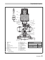
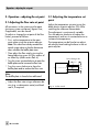
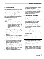
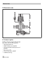
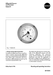
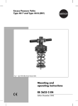
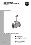
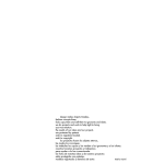
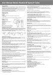
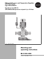
Differential Pressure and Temperature Regulator
with Flow Limiter
Type 2479/2430 K
Special version DN 15
with differential pressure set point ∆p = 0.5 bar
Fig. 1 ⋅ Type 2479/2430 K
Mounting and
operating instructions
EB 3132-4 EN
Edition November 2000
Design and principle of operation
1. Design and principle of operation
The regulator consists of a control valve
with restriction, seat and plug, a closing
actuator with operating diaphragm and a
thermostat with set point adjuster, capillary
tube and temperature sensor. The regulator
is designed to maintain the differential pressure and the temperature at the adjusted set
point. The flow limiter can be adjusted by
turning the adjusting screw (8.3) located in
the valve body. The valve closes when the
controlled value increases.
The process medium flows through the valve
in the direction indicated by the arrow. The
free area between the adjustable restriction
(baffle plate) (8.5) and the plug (3) determines the flow rate. The high pressure of the
plant (flow line) is transmitted to the lower
diaphragm chamber of the actuator via the
control line (7) provided by the customer.
The low pressure downstream of the restriction is applied to the low pressure side of the
operating diaphragm (6.1) through a bore in
the plug. The differential pressure created by
the restriction (baffle plate) is converted into
a positioning force acting on the operating
diaphragm. This force is used to move the
plug according to the force of the positioning spring (5).
In the sensor, the temperature of the medium produces a pressure which is transmitted to the operating bellows (23) via the capillary tube (24) and converted into a positioning force. This force is used to move the
baffle plate (8.5) via the coupling rod (9) according to the force of the spring (21) pretensioned by the set point adjuster (22). The
largest signal is always used to actuate the
valve.
Assembly, start-up and operation of the device may only be performed by
trained personnel familiar with this product.
According to these mounting and operating instructions, trained personnel
2
refers to individuals who are able to judge the work they are assigned to and
recognize potential hazards due to their specialized training, their knowledge
and experience as well as their knowledge of the applicable standards.
Any hazards which could be caused at the regulator by the process medium or
the operating pressure must be prevented by means of appropriate measures.
Moreover, it must be ensured that the control valve is only used in applications
where operating pressure and temperatures do not exceed the operating
values which are based on the valve sizing data submitted with the order.
Proper shipping and appropriate storage are assumed.
EB 3132-4 EN
Design and principle of operation
23
22
21
25
24
9
8
20
10
8.3
1
8.5
2
3
4
5
6.2 6.1
1
2
3
4
5
6
6.1
6.2
7
8
Valve body
Seat
Plug
Plug stem
Positioning spring
Actuator
Operating diaphragm with plates
Screws
Control line
Mounting part
8.3
8.5
9
10
20
21
22
23
24
25
7
6
Adjusting screw
Baffle plate (restriction)
Coupling rod
Connection nut
Control thermostat
Spring
Set point adjuster
Operating bellows
Capillary tube
Temperature sensor
Tightening torques
Pos. 10
Connection nut
20 Nm
Pos. 3
Plug
70 Nm
Pos. 6.2
Screws
8 Nm
Fig. 2 ⋅ Sectional drawing
EB 3132-4 EN
3
Installation
2. Installation
2.2 Control line
The regulator should generally be installed
into the low pressure line, e.g. the return
flow pipe. When used in district heating systems, the regulator must only be installed
into the return flow pipe.
The control line with a pipe diameter of
6 mm must be adapted and installed on
site. For the piping arrangement, refer to
the installation schematics, Fig. 3.
2.1 Mounting position
2.3 Strainer
Install the regulator in the horizontal
pipeline so that either the actuator or the
thermostat is vertically suspended. (Note
that the actuator must face upward and that
the thermostat must face downward if the
medium temperature exceeds a maximum
of 110°C).
Use the supplied screw joints with weld-on
fittings for standard connection.
The medium must flow through the valve in
the direction indicated by the arrow on the
valve body.
Since sealing particles, globules and other
impurities carried along by the process
medium could impair the proper functioning
of the valve, especially tight shut-off, a strainer (SAMSON Type 1NI) should be installed upstream of the regulator.
The strainer must be installed so that the
medium flows through it in the direction indicated by the arrow on the strainer body.
The filter insert must be vertically suspended. Make sure that ample space is available to remove the filter.
4
+
4
1
Fig. 3 ⋅ Installation schematics
4
EB 3132-4 EN
3
2
1
1
2
3
4
Shut-off valve
Strainer
Regulator
Pressure gauge
Installation
2.4 Additional installation instructions
We recommend that you install one handoperated shut-off valve upstream of the strainer and one downstream of the regulator.
This allows the plant to be shut down for
cleaning the strainer or maintaining the regulator.
To monitor the pressures prevailing in the
plant, install one pressure gauge upstream and
one downstream of the regulator. To monitor
the adjusted temperature set point, a thermometer must be installed and immersed in the
controlled medium near the sensor.
2.5 Installing the temperature sensor
For further details on the Type 2430 K
Thermostat, refer to the "Mounting and
operating instructions" EB 2430 EN.
For the Type 2430 (vapor pressure), refer to
EB 2430-3 EN.
The temperature sensor of the Type 2430 K
Thermostat may be mounted in any desired
position. It must be entirely immersed in the
controlled medium. The sensor should be installed in a location where overheating or
considerable idle times cannot occur.
A welding socket with a G 1/2 or G 3/4 female thread connection should be welded
to the position where the sensor is to be installed.
Seal the screw gland or thermowell into the
welding socket. Insert the sensor and fasten
it with the clamping screw.
CAUTION
To prevent damage caused by corrosion, it is important to make sure on
installing the sensor or thermowell
that only the same kind of materials
are used together. For instance, do
not use a sensor or thermowell
made of non-ferrous metal in a stainless steel heat exchanger. In this
case, the sensor should be used together with a stainless steel thermowell.
2.5.1 Capillary tube
The capillary tube should be routed such
that it cannot be damaged. The smallest
bending radius must be minimum 50 mm.
Any excess tube should be neatly coiled up.
The tube may not under any circumstances
be bent or shortened. The ambient temperature around the tube should fluctuate as little
as possible.
2.6 Assembling the valve and the
thermostat
Attach the thermostat to the mounting part
of the valve and screw it down by means of
a connection nut (10), tightening torque 20
Nm.
EB 3132-4 EN
5
Operation – adjusting the set point
3. Operation – adjusting the set point
3.1 Adjusting the flow rate set point
All consumers in the system must be open
(minimum system resistance). Bypass lines,
if applicable, must be closed.
To adjust or change the set point of the flow
limiter, proceed as follows:
First, set the temperature to the maximum value using the set point adjuster.
Note: This value must always exceed the
actual system value so that the thermostat
does not affect the baffle plate stem.
3.1 Adjusting the temperature set
point
Adjust the temperature set point using the
black plastic set point adjuster (22) while
watching the reference thermometer.
The adjustment is continuously variable.
Turn the adjuster clockwise to reduce the
temperature, and turn it counterclockwise to
increase the temperature.
The temperature can be fixed at an adjusted value by lead-sealing the bore in the set
point adjuster.
Then adjust the flow rate by turning the
19 mm hexagon bit
17
Ø 17
lateral adjusting screw (8.3) by means of
an Allen key (width across flats 4):
Turn the screw counterclockwise to open the
baffle plate and to increase the flow rate.
Turn the screw clockwise to close the
baffle plate and to reduce the flow rate.
Note:
The baffle plate is closed when delivered.
Adjust the flow rate using a reference device (e.g. a calorimetric meter) and leadseal it, if required.
6
EB 3132-4 EN
Fig. 4 ⋅ Socket wrench
Operation – adjusting the set point
4. Troubleshooting
If the valve does not close tightly, the cause
may be a contaminated seat or plug, or valve seat and plug no longer give tight shutoff because of wear and tear. If the flow
rate deviates considerably from the adjusted set point, e.g. rapidly increasing flow
rate, inspect the operating diaphragm for leaks and replace it, if necessary.
CAUTION
Always relieve the pressure from the
part of the plant to be worked on
and drain it prior to performing any
assembly work on the regulator. Remove the regulator from the
pipeline to perform any assembly
work.
4.1 Cleaning or replacing the plug
1. Unscrew the thermostat and the control
line, and remove the regulator from the
pipeline.
2. Loosen the screws (6.2) and remove the
lower diaphragm case with the diaphragm (6.1) and the diaphragm
plates.
3. Unscrew and remove the guide nipple
of the plug section (3) using a socket
wrench (Order No. 1280-3001).
This wrench can be made, for instance,
from a GEDORE screwdriver bit (IN 1919) by boring a 17-mm hole with a diameter of 17 mm into the 19-mm hexagon bit as shown in Fig. 4.
4. Clean the seat and plug thoroughly.
Should the plug be damaged, replace
the complete plug section.
5. Check the control line for any blockages.
6. To reassemble the regulator, proceed in
reverse order. Apply the tightening
torques according to Fig. 2.
4.2 Replacing the diaphragm
1. Unscrew the thermostat and the control
line (7).
2. Loosen the screws (6.2) and remove the
lower diaphragm case with the diaphragm and diaphragm plates.
3. Replace the complete diaphragm
section including the diaphragm plates.
4. To reassemble the regulator, proceed in
reverse order.
4.3 Replacing the baffle plate
1. Unscrew the coupling nut in order to remove the thermostat from the mounting
part of the valve.
CAUTION
Unscrew the adjusting screw (8.3) before
proceeding!
2. Unscrew the mounting part (8) including the baffle plate by means of a sokket wrench (see Fig. 4, Order No.
1280-3001) and pull it out of the valve
body.
3. Replace the parts. To reassemble the regulator, proceed in reverse order. Apply the tightening torques according to
Fig. 2.
EB 3132-4 EN
7
Dimensions in mm
85
167.5
5. Dimensions in mm
Ø116
6. Customer inquiries
Should you have any inquiries about the regulator, please submit the following details:
Type and nominal size
Model Number (see nameplate)
Upstream and downstream pressures of
8
the valve
Flow rate in m3/h
Has a strainer been installed?
Installation drawing
EB 3132-4 EN
EB 3132-4 EN
9
EB 3132-4 EN
S/C 2001-01
SAMSON AG ⋅ MESS- UND REGELTECHNIK
Weismüllerstraße 3 ⋅ D-60314 Frankfurt am Main
Phone (0 69) 4 00 90 ⋅ Telefax (0 69) 4 00 95 07
Internet: http://www.samson.de