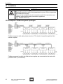
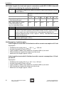
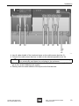
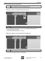
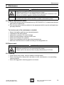
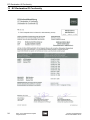
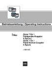
1
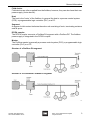
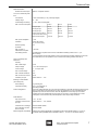
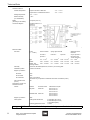
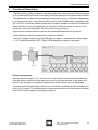
Operating Instructions Zone 1 Ex i Field Device Coupler 4 Spurs > 9411/21 Contents 1 Contents 1 2 3 4 5 6 7 8 9 10 11 12 13 14 2 Contents ................................................................................................................2 General Information ...............................................................................................2 General Safety Instructions ...................................................................................4 Technical Data ......................................................................................................6 Designated Use ...................................................................................................10 Functional Description .........................................................................................11 Device design ......................................................................................................12 Transport, Storage and Disposal .........................................................................12 Assembly .............................................................................................................13 Installation ...........................................................................................................14 Putting into Service .............................................................................................22 Maintenance ........................................................................................................23 EC-Declaration Of Conformity .............................................................................24 Certification Drawing ...........................................................................................25 General Information 2.1 Manufacturer R. STAHL Schaltgeräte GmbH Am Bahnhof 30 74638 Waldenburg Germany Phone: +49 7942 943-0 Fax: +49 7942 943-4333 Internet: www.stahl-ex.com 2.2 Operating Instructions Information ID-No.: 161935 / 941160310010 Publication Code: 2014-04-25·BA00·III·en·07 We reserve the right to make technical changes without notice. 2.3 Definitions of terms Trunk The trunk is the main bus line when describing fieldbus topology. Terminating resistor Both ends of the trunk are connected with a terminating resistor (100 ohms + 1 mF). Spur A spur connects the trunk with the field devices. Spurs can be further subdivided into additional branches. Fieldbus power supply The fieldbus power supply feeds DC power to field devices on the fieldbus and effects impedance adaptation between the fieldbus and the main power. Electrically, the host behaves the same as a field device. 2 Zone 1 Ex i Field Device Coupler 4 Spurs 9411/21 161935 / 941160310010 2014-04-25·BA00·III·en·07 General Information Field device Field devices are often supplied from the fieldbus, however, they can also have their own power supply (4-wire device). Host The host is the “brain“ of the fieldbus. In general the host is a process control system (PCS), a programmable logic controller (PLC) or a PC. Segment A segment in this context indicates the entire unit consisting of trunk, terminating resistors and all spurs. DP/PA coupler The DP/PA coupler connects a Profibus PA segment with a Profibus DP. The fieldbus power supply is integrated in the DP/PA coupler. Master The Profibus master is generally a process control system (PCS), a programmable logic controller (PLC) or a PC. Structur of a Profibus PA segment 11462E02 Structur of a Foundation Fieldbus H1 segment 11463E02 161935 / 941160310010 2014-04-25·BA00·III·en·07 Zone 1 Ex i Field Device Coupler 4 Spurs 9411/21 3 General Safety Instructions 3 General Safety Instructions 3.1 Safety Instructions for Assembly and Operating Personnel The operating instructions contain basic safety instructions which are to be observed during installation, operation and maintenance. Non-observance will endanger persons, plant and the environment. WARNING Danger due to unauthorised work being performed on the device! There is a risk of injury to persons and damage to equipment. Assembly, installation, commissioning, operation and maintenance must only be performed by personnel who are both authorised and suitably trained for this purpose. Before assembly/commissioning: Read through the operating instructions. Give adequate training to the assembly and operating personnel. Ensure that the contents of the operating instructions are fully understood by the personnel in charge. The national installation and assembly regulations (e.g. IEC/EN 60079-14) apply. When operating the devices: Ensure the operating instructions are made available on location at all times. Observe safety instructions. Observe national safety instructions and accident prevention regulations. Only run the device according to its performance data. Servicing/maintenance or repair work which are not described in the operating instructions must not be performed without prior agreement with the manufacturer. Any damage may render explosion protection of the device null and void. No changes to the device impairing their explosion protection are permitted. Install and use the device only if it is undamaged, dry and clean. If you have questions: Contact the manufacturer. 3.2 Warnings Warnings are sub-divided in these operating instructions according to the following scheme: WARNING Type and source of the danger! Possible consequences. Measures to avoid danger. They are always identified by the signalling word “WARNING“ and sometimes also have a symbol which is specific to the danger involved. 4 Zone 1 Ex i Field Device Coupler 4 Spurs 9411/21 161935 / 941160310010 2014-04-25·BA00·III·en·07 General Safety Instructions 3.3 Symbols Used X Action request: Describes actions to be carried out by the user. Reaction sign: Describes the results or the reactions to the actions taken. Bullet Sentinel: Describes the notes and recommendations. Warning sign; danger from energised parts! Warning sign: Danger due to an explosive atmosphere! 161935 / 941160310010 2014-04-25·BA00·III·en·07 Zone 1 Ex i Field Device Coupler 4 Spurs 9411/21 5 Technical Data 4 Technical Data Explosion protection Coupler mounted on DIN rail Gas explosion protection ATEX E II 2(1)G Ex mb eb ib [ia] IIC T4 IECEx Ex mb eb ib [ia] IIC T4 Dust explosion protection ATEX E II (1)D [Ex ia] IIIC IECEx [Ex ia] IIIC Coupler in the standard enclosure Gas explosion protection ATEX E II 2(1)G Ex mb eb ib [ia] IIC T4 IECEx Ex mb eb ib [ia] IIC T4 Dust explosion protection ATEX E II 2(1)D Ex tD A21 IP 6X T80°C [ia D] IECEx Ex tD A21 IP 6X T80°C [ia D] Certificates ATEX IECEx Installation BVS 06 ATEX E 004 X IECEx BVS 08.0057 X in Zones 1 and 2, Zones 21 and 22 (dust), Class I, Zones 1 and 2, Class I Division 2 and in the safe area suitable enclosure necessary e.g. R. STAHL Series 8146 (plastic) or 8125, 8150 (stainless steel) Safety data (CENELEC) per spur FISCO (IEC 60079-27) Max. voltage U0 15.7 V Max. current I0 245 mA Max. power P0 960 mW Max. connectable capacitance Co for IIC/IIB 476 nF / 2878 nF Max. connectable inductance Lo for IIC/IIB 0.58 mH / 2.9 mH Max. internal capacitance Ci 1.1 nF Max. internal inductance Li ~ 0 mH Insulation voltage Um 253 V Power supply not required, the Field Device Coupler is powered from the trunk Galvanic isolation Test voltage according to EN 50020 6 Ex i spurs to Ex e trunk 1.5 kV AC Ex i spur to Ex i spur No galvanic isolation Zone 1 Ex i Field Device Coupler 4 Spurs 9411/21 161935 / 941160310010 2014-04-25·BA00·III·en·07 Technical Data Data transmission between trunk and spurs passive, no repeater function Trunk, non-intrinsically safe / Ex e Connections 2 trunk connections (in, out), internally bridged Voltage range 16 ... 32 V Undervoltage monitoring U < 16 V, spurs de-energised Max. current consumption at 16 V at 24 V at 32 V 0 mA per spur 28 mA 24 mA 22 mA 20 mA per spur 120 mA 80 mA 65 mA 40 mA per spur 220 mA 140 mA 105 mA 3 spurs at 40 mA each, 235 mA 1 spur in the short-circuit 150 mA 105 mA Short-circuit all spurs < 60 mA < 50 mA < 80 mA Max. power dissipation 1.8 W Indication Green LED "PWR" (U ) 16 V from trunk) Reverse polarity protection yes Max. number of Field Device Couplers 4 per trunk Terminating resistor The field device couplers have a built-in, switchable terminating resistor 100 Ω + 1 μF (IEC 61158-2). A jumper between the terminals TERM 1 and 2 connects the terminating resistance to the trunk. As an alternative, it is also possible to use an external terminating resistor series 9418. Spurs, intrinsically safe FISCO Ex i Quantity 4 Max. cable length 120 m Output voltage ≥ 10 V at 40 mA per spur Current range 0 ... 41 mA per spur Min. no-load voltage 12 V Max. internal resistance 65 Ω Max. short-circuit current 50 mA Indication per spur Yellow LED "S1" ... "S4" Earthing of cable shields (trunk and spurs) Direct earthing on grounding bar Capacitive earthing via 4.7 nF at terminal „S“; (grounding bolt M6) Power management If the trunk voltage exceeds 16 V, the spurs are switched on one after the other to prevent a high start-up current due to the field devices. A short circuit detected on a spur will deactivate the respective spur until the short-circuit is removed. Regardless of how many spurs are shortcircuited, the trunk is loaded with max one short-circuit current. This minimises the current consumption of the trunk and the power dissipation under all operating conditions. Fault detection Spur short-circuit ≥ 42 ... 50 mA Indication of short-circuit per spur Yellow LED "S1" ... "S4", flashes Collective error message Red LED "ERR" flashes Error indication on field device coupler Red LED "ERR" Electromagnetic compatibility 161935 / 941160310010 2014-04-25·BA00·III·en·07 Tested to the following standards and regulations: EN 61326 (IEC/EN 61000-4-1...6 and 11; EN 55022 class B); NAMUR NE 21 (IEC/EN 61000-4-1...6, 8 and 11; EN 55022 class B) Zone 1 Ex i Field Device Coupler 4 Spurs 9411/21 7 Technical Data Ambient conditions Ambient temperature Coupler mounted on DIN rails: - 40 ... + 75 °C Coupler built in a standard enclosure: - 20 ... + 70 °C Storage temperature - 40 ... + 75 °C Relative humidity (no condensation) < 95 % MTBF (according to SN 29500) 109 years (at 40 °C) Connection diagram 10911E01 Mechanical data 3 pole (+, -, screen) Terminals rigid screw terminals spring cage terminals detachable screw terminals trunk Ex e spurs Ex i trunk Ex e only for spurs Ex i (trunk Ex e see “screw terminals“) 0.2 ... 4 mm2 spurs Ex i 0.5 ... 2.5 mm2 0.08 ... 2.5 mm2 2 2 0.25 ... 2.5 mm2 0.08 ... 1.5 mm2 0.25 ... 2.5 mm2 flexible 0.25 ... 2.5 mm 0.5 ... 2.5 mm flexible, end covering sleeves 0.25 ... 2.5 mm2 0.5 ... 1.5 mm2 2 0.08 ... 2.5 mm Assembly on DIN rail, EN 50022 (NS 35/15, NS 35/7.5) or mounting plate Installation position vertical or horizontal 0.2 ... 4 mm2 Degree of protection Enclosure IP30 Ex i terminals IP20 Ex e terminals IP30, cover closed (enclosure may be opened in hazardous area while connected to power) Fire protection class (UL-94) HB Field Device Coupler in a standard enclosure Version enclosure Series Field Device Coupler polyester 8146/.061 9411/21-211-31 9411/21-221-31 9411/21-231-31 stainless steel 8125/.061 9411/21-212-31 9411/21-222-31 9411/21-232-31 Degree of protection IP66 Cable glands cable glands Series 8161 4 x M20 blue (Ex i spurs) 2 x M20 black (Ex e trunk) 1 x M16 black (earth) breathing gland Series 8162 1 x M25 8 material Additional technical data for layout and designs: see the data sheet Zone 1 Ex i Field Device Coupler 4 Spurs 9411/21 161935 / 941160310010 2014-04-25·BA00·III·en·07 Technical Data 15 mm / 0.59 " 91 mm / 3.58 " 73,5 mm / 2.89 " 208,5 mm / 8.21 " 204 mm / 8.03 " 168 mm / 6.61 " ø 5,5 mm / 0.22 " 111 mm / 4.37 " 126 mm / 4.96 " 128 mm / 5.04 " m m 5 3, 4 " R 0.1 R 10944E00 10946E00 91 mm / 3.58 " 9411/21-2.1-41 Enclosure 8146/.S71 incl. Field Device Coupler 360 mm / 14.17 " 320 mm / 12.60 " ø 7 mm / 0.28 " 237 mm / 9.33 " 212,5 mm / 8.37 " 7 mm / 0.28 " 5,5 mm / 0.22 " 10 mm / 0.39 " 9411/21-2.0-41 Field Device Coupler without enclosure 2 mm / 0.08 " 7 mm / 0.28 " 5,5 mm / 0.22 " 340,5 mm / 13.41 " 322,5 mm / 12.7 " 199 mm / 7.83 " 118 mm / 4.65 " 82 mm / 3.23 " Dimensional Drawings (All Dimensions in mm / inches) - Subject to Alterations 10948E00 9411/21-2.2-41 Enclosure 8125/.071 incl. Field Device Coupler 161935 / 941160310010 2014-04-25·BA00·III·en·07 Zone 1 Ex i Field Device Coupler 4 Spurs 9411/21 9 Designated Use 5 Designated Use WARNING Use the device for its intended purpose only! Otherwise, the manufacturer’s liability and warranty expire. Only use the device under the operating conditions described in the operating instructions. The device must be used in areas subject to explosion hazards only according to these operating instructions. The series 9411/21 field device coupler is suitable for use in Zone 1, 2, 21 and 22 hazardous areas. It is used for connecting up to four intrinsically safe field devices to a non-intrinsically safe trunk. In so doing, the trunk and spurs are galvanically isolated. Intended use X For all fieldbuses with a IEC 61158-2 physical layer, e.g. Foundation Fieldbus H1 and Profibus PA. X For non-instrinsically safe trunks, Ex e connections. X For intrinsically safe spurs (Ex i and FISCO), to connect intrinsically safe field devices. Overview of explosion protection for field device coupler, trunk and spurs Field device coupler EX e / Ex i Zone 0 9411/21-211-31, 9411/21-220-31, 9411/21-230-31 with enclosure not permitted not 9411/21-211-31, permitted 9411/21-221-31, 9411/21-231-31 with polyester enclosure 8146/.61 Zone 1 Zone 2 Zone 21 Zone 22 non-hazardous area Ex e enclosure required Enclosure as per Enclosure as per IEC/EN 60079-14 IEC/EN 61241-1 required required Enclosure as per o.k. IEC/EN 61241-1 required o.k. o.k. o.k. o.k. o.k. 9411/21-212-31, 9411/21-222-31, 9411/21-232-31 with stainless steel enclosure 8125/.61 Trunk not permitted Ex i Ex nA o.k. o.k. o.k. Spurs Ex ia Ex ia Ex nL o.k. o.k. o.k. The R. STAHL enclosure series 8146 (polyester), 8125 (sheet steel or stainless steel), 8126 (stainless steel) meet the requirements. WARNING When mounting in an EX e enclosure: Affix an indication label (in accordance with IEC/EN 60079-7): “Non-intrinsically safe circuits protected by internal IP30 cover“ 10 Zone 1 Ex i Field Device Coupler 4 Spurs 9411/21 161935 / 941160310010 2014-04-25·BA00·III·en·07 Functional Description 6 Functional Description The field device coupler is used for connecting up to four intrinsically safe field devices to a non-instrinsically safe trunk. In so doing, the trunk and spurs are galvanically isolated. The field device coupler functions at the physical level only, e.g., it functions independently of the protocol used. It can therefore be used for every fieldbus that is compliant with IEC 61158-2. At this time, these include the Foundation Fieldbus H1 and the Profibus PA. Each field device can be supplied with a maximum of 40 mA current. As short circuit protection, each spur features a 50 mA current limiting function. A termination resistor is built-in and can be activated/deactivated via a jumper. Cable shield can either be capacitively or directly earthed. The trunk voltage connecting to the field device coupler is monitored for undervoltage (< 16 V) and indicated by a LED. Other LEDs indicate the status of the spurs. 11458E02 Power management As soon as the voltage of 16 V on the trunk is exceeded , the spurs are activated one after the other to prevent a high start-up current by the field devices. In the event of a short-circuit, the spur in question is deactivated until the short-circuit is eliminated. If several spurs are affected by a short-circuit, the trunk is loaded only with maximum one short-circuit current. This minimises the current consumption of the trunk and the power loss of the coupler under all operating conditions. 161935 / 941160310010 2014-04-25·BA00·III·en·07 Zone 1 Ex i Field Device Coupler 4 Spurs 9411/21 11 Device design 7 Device design 11455E00 1 2 3 4 5 6 7 8 8 Ex e area; The Ex e connection terminals for the trunk and the jumper for activating the terminating resistor are protected by a hinged cover (IP 30). Ex i area; Ex i connection terminals for spur 1 ... spur 4 Operation indicating LEDs for spur 1 ... spur 4 Operation indicating LEDs for PWR (power) and ERR (error) Cable screen bus bar for cable shields with slidable terminals Ground bolt for earthing Partition plate; guarantees prescribed spacing of lead wires between Ex e and Ex i connection terminals Park position for jumper Transport, Storage and Disposal Transport Shock-free in its original carton, do not drop, handle carefully. Storage Store in a dry place in its original packaging. Permitted temperature range for storage in original packaging: - 40 °C ... + 75 °C. 12 Zone 1 Ex i Field Device Coupler 4 Spurs 9411/21 161935 / 941160310010 2014-04-25·BA00·III·en·07 Assembly Disposal Ensure environmentally friendly disposal of all components according to the legal regulations. 9 Assembly WARNING Incorrectly installed components! Explosion protection cannot be guaranteed any more if the components are incorrectly installed. Carry out the assembly in strict accordance with the instructions and national safety and accident prevention regulations (e.g. IEC/EN 60079-14). Do not select a mounting location that necessitates the cable lengths that exceed the maximal permissible values (see chapter 10.3, Cable lengths). 9.1 Mounting with enclosure Relevant to field device couplers 9411/21-211-31, 9411/21-221-31 respectively 9411/21-231-31 in polyester enclosure 8146/.61 and 9411/21-211-31, 9411/21-221-31 respectively 9411/21-231-31 in stainless steel enclosure 8146/.71 Installation with screws (hole spacing: see chapter 4, Technical data) 9.2 Mounting without enclosure Relevant to field device couplers 9411/21-210-31, 9411/21-220-31 respectively 9411/21-230-31 Field device couplers without enclosures are always delivered ready for DIN rail mounting. X For installation in non-hazardous areas, e.g.g in normal switch cabinet or open rack. X For installation in an enclosure not mentioned above. 161935 / 941160310010 2014-04-25·BA00·III·en·07 Zone 1 Ex i Field Device Coupler 4 Spurs 9411/21 13 Installation 10 Installation WARNING Incorrectly installed components! Explosion protection cannot be guaranteed any more if the components are installed incorrectly. Carry out the installation in strict accordance with the instructions and national safety and accident prevention regulations (e.g. IEC/EN 60079-14). 10.1 Examples of fieldbus segment topologies 11460E02 Fieldbus segment with „daisy chain structure“. The trunk is looped through the field device couplers. 11461E02 Fieldbus segment in which the field device couplers are connected to the trunk with junction boxes (T-connectors). 14 Zone 1 Ex i Field Device Coupler 4 Spurs 9411/21 161935 / 941160310010 2014-04-25·BA00·III·en·07 Installation 11464E02 Fieldbus segment with star structure. 10.2 Proof of intrinsic safety Proof of intrinsic safety in accordance with FISCO A spur is intrinsically safe if: X the field device is certified in accordance with FISCO. X the conditions regarding cable values as per IEC 60079-27 are adhered to: RC 15 ...150 Ohm/km LC 0,4 ... 1mH/km CC 45 ... 200nF/km Proof of intrinsic safety in accordance with the classic „entity concept“ A spur is intrinsically safe if the safe maximum values for the field device and spur connections are met: Spur of field device coupler Field device U0 ( Ui I0 ( Ii P0 ( Pi C0 ) Ci + CCable L0 ) Li + LCable Whereby, CCable and LCable are the results of the total capacity, respectively, inductivity of the spur cable, which, in turn, depends on the cable length. 161935 / 941160310010 2014-04-25·BA00·III·en·07 Zone 1 Ex i Field Device Coupler 4 Spurs 9411/21 15 Installation 10.3 Cable lengths for trunk and spurs in accordance with IEC 61158-2, Annex B (without considering the explosion protection) The maximum length for all cables (all trunks, all spurs) per segment must not exceed 1900 m. Max. cable length for spurs, 1 field device per spur Max. cable length for spurs, 2 field devices per spur (e.g. for redundant hosts) Number of all field devices on the segment, including host(s) 1 ... 12 13 ... 14 15 ... 18 19 ... 24 25 ... 30 120 m 90 m 60 m 30 m 1m 90 m 60 m 30 m 1m 1m The actual trunk and spur lengths can be shorter due to voltage drop. The maximum length of an Ex i spur according to IEC 60079-27 (FISCO) is 30 / 60 m. From the viewpoint of the FISCO model, the Ex i spurs of a field device coupler are to be considered as a new segment (whereby the maximum segment length = trunk + spurs = 1000 m). The table above can be used for this purpose. The following generally applies: Spurs should be kept as short as possible. Maximum spur length = 120 m 10.4 Examples of cable lengths Cable lengths for trunk with 12 field devices with a current consumption of 15 mA: Assumption: X X X X Fieldbus power supply with Uout > 25 V / Iout > 350 mA. Current consuption of host is 20 mA. Type A fieldbus cables (loop resistance: 48 ohms/1000 m) are used. Three field device couplers lie at the end of the trunk. Maximum trunk length: approx. 600 m. Cable length for trunk with 16 field devices with a current consumption of 15 mA per device: Assumption: X X X X 16 Fieldbus power supply with Uout > 25 V / Iout > 350 mA. Current consumtion of host is 20 mA. Type A fieldbus cables (loop resistance: 48 ohms/1000 m) are used. Four field device couplers lie at the end of the trunk. Maximum trunk length: approx. 380 m Zone 1 Ex i Field Device Coupler 4 Spurs 9411/21 161935 / 941160310010 2014-04-25·BA00·III·en·07 Installation 10.5 Connection WARNING Laying of intrinsically safe and non-intrinsically safe cabling together: Explosion protection is not guaranteed any longer. Always lay intrinsically safe and non-intrinsically safe cables in separate paths. 11459E02 11452E00 Trunk WARNING Open cover on the non-intrinsically safe trunk: Explosion protection is not guaranteed any longer. The fieldbus must be deactivated before opening the cover. Secure the fieldbus against unauthorised activation. TRUNK IN and TRUNK OUT (+,-,S) are connected through internally in the field device coupler. Disconnect the fieldbus from the power supply. Open enclosure/cover. Insert leads in the corresponding terminals: TRUNK IN: Lead from host or fieldbus power supply. TRUNK OUT: If applicable, lead to the next field device coupler. Close/screw tight the terminals. Close cover/enclosure. 161935 / 941160310010 2014-04-25·BA00·III·en·07 Zone 1 Ex i Field Device Coupler 4 Spurs 9411/21 17 Installation Spur safe spur connections can be worked on while connected to Intrinsically power. Only one field device can be connected per spur connection. Open enclosure. Insert leads in the corresponding terminals. Close/screw tight the terminals. Close enclosure. 10.6 Earthing Field device coupler without enclosure The field device coupler is not required to be connected to earth because the intrinsically safe and non-intrinsically safe circuits are galvanically isolated from each other. If the cable shields are to be capacitively earthed (by connecting to the “S“ marked terminals): Connect the earthing bolt to the cable screen bus bar (delivery condition from factory). Connect the cable screen bus bar to earth. Field device coupler with metal enclosure Connect the enclosure to earth via the shortest possible route. 10.7 Earthing of cable shields There are many, and sometimes inconsistent, regulations regarding earthing of cable shielding: X IEC / EN 60079-14, section 12.2.2.3 X Profibus Technical Guideline „Profibus PA“ User and Installation Guideline, section 3.3.3 X Fieldbus Foundation „System Engineering Guidelines“ AG 181, section 6.2f If high-quality potential equalisation exists within the plant: 18 This shielding concept is recommended by R. STAHL. The direct earthing the cable shielding at both cable ends is the best solution in view of electromagnetic compatibility. The prerequisite for this is high-quality potential equalisation. Zone 1 Ex i Field Device Coupler 4 Spurs 9411/21 161935 / 941160310010 2014-04-25·BA00·III·en·07 Installation 11457E00 Lay all cable shields of the trunk and spurs on the cable screen bus bar (1). Connect the cable screen bus bar to earth via the shortest possible route (2). When installingdirectly (with screws) in metal enclosure 8125, the earthing bolt is electrically connected via mounting to the enclosure. Directly earth the cable shield of the trunk at the host/fieldbus power supply side (as a rule, at the fieldbus power supply). Directly earth the cable shields of the spurs at the field devices. 161935 / 941160310010 2014-04-25·BA00·III·en·07 Zone 1 Ex i Field Device Coupler 4 Spurs 9411/21 19 Installation If no high-quality potential equalisation exists within the plant: 11456E00 Connect the cable shields of the trunk to the “TRUNK IN S“ terminals and, if needed, to the “TRUNK OUT S“ (1). Connect the earthing bolt (2) with the cable screen bus bar so that good conductance is achieved (delivery condition from factory). Connect the cable screen bus bar to earth via the shortest possible route (3). In this way, the cable shield of the trunk is capacitively earthed. When installing directly (with screws) in metal enclosure 8125, the earting bolt is electrically connected via mounting to the enclosure. Lay the cable shields of the spurs on the cable screen bus bar. Directly earth the cable shield of the trunk at the host/fieldbus power supply side (as a rule, at the fieldbus power supply). Insulate the cable shields of the spurs connecting at the field devices. Do not earth them. 20 Zone 1 Ex i Field Device Coupler 4 Spurs 9411/21 161935 / 941160310010 2014-04-25·BA00·III·en·07 Installation 10.8 Terminating resistor (terminator) A terminating resistor is required at both ends of the trunk. Spurs are operated without terminating resistors. Field device coupler is located at the end of the trunk 11453E00 The terminals on the „TRUNK OUT“ terminal block are not to be used. Remove the factory-provided jumper from the park position (1). Insert the jumper in terminals „1“ and „2“ on the „TERM“ terminal block (2). Close/screw tight the terminals. The built-in terminating resistor is activated. Field device coupler is not located at the end of the trunk 11454E00 The terminals on the „TERM“ terminal block are not to be used. Insert the factory-provided jumper in the park position (1). The built-in terminating resistor is not activated. 161935 / 941160310010 2014-04-25·BA00·III·en·07 Zone 1 Ex i Field Device Coupler 4 Spurs 9411/21 21 Putting into Service 11 Putting into Service Before commissioning Test the components for correct operation and installation in accordance with the operating instructions and other applicable specifications. Check that cables and lines are clamped properly. Inspect housing for damage. Inspect housing for foreign bodies. Check whether all unused cableglands and holes are sealed off properly. The voltage on the trunk must be at least 16 V DC. The voltage to the connected field devices must be at least 9 V DC. Commissioning Observe the national regulations when commissioning. Follow the Directives in accordance with EN 60079-17 when conducting function inspections. LED indicators, functional description 11451E00 PWR, green ERR, red S (1 ... 4), yellow OFF ON OFF OFF OFF ON blinking blinking ON 22 Zone 1 Ex i Field Device Coupler 4 Spurs 9411/21 Description No voltage on the trunk Voltage on trunk o.k. U ) 16 V Open-circuit on the corresponding spur Spur not connected I ( 1 mA Corresponding spur connected to field device, 3 mA ( I ( 50 mA Short-circuit on the corresponding spur 40 mA ( I ( 50 mA Internal device fault 161935 / 941160310010 2014-04-25·BA00·III·en·07 Maintenance 12 Maintenance WARNING Danger from energised parts! Explosion protection is not guaranteed any longer. Switch off the power to the fieldbus before opening the enclosure cover. Secure the fieldbus against unauthorised activation. The enclosure may be opened while connected to power. Intrinsically safe spurs can be worked on while connected to power. 12.1 Regular Maintenance Work Consult the relevant national regulations (e.g. IEC/EN 60079-17) to determine the type and extent of inspections. Plan the intervals so that any defects in the equipment which may be anticipated are promptly detected. To check as part of the maintenance schedule: X X X X X X X Check that cables and lines are clamped properly. Tightness of the cable glands. Inspect the enclosure for visual damage. Check the seal between enclosure and cover. Check the enclosure for moisture Check the compliance with the permitted temperatures. Make sure that the device is used according to its designated use. 12.2 Repair work WARNING Danger due to improper maintenance/repairs Explosion protection is not guaranteed any longer. Repair work to the device must only be performed by R. STAHL. 12.3 Cleaning X Clean with a cloth, brush, vacuum cleaner or similar items. X When cleaning with a damp cloth use water or mild, non-abrasive, non-scratching cleaning agents. X Never use aggressive cleaning agents or solvents. 161935 / 941160310010 2014-04-25·BA00·III·en·07 Zone 1 Ex i Field Device Coupler 4 Spurs 9411/21 23 EC-Declaration Of Conformity 13 EC-Declaration Of Conformity 24 Zone 1 Ex i Field Device Coupler 4 Spurs 9411/21 161935 / 941160310010 2014-04-25·BA00·III·en·07 Certification Drawing 14 Certification Drawing 161935 / 941160310010 2014-04-25·BA00·III·en·07 Zone 1 Ex i Field Device Coupler 4 Spurs 9411/21 25