1
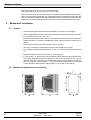
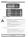
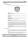
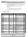
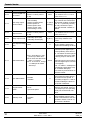
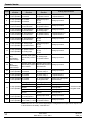
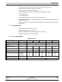
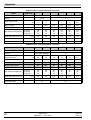
®
BERGES
User Guide
Smart Drive
Smart Wireless Drive+
Table of Contents
1
General. . . . . . . . . . . . . . . . . . . . . . . . . . . . . . . . . . . . . . . . . . . . . . . . . . . . . . . . . . . . . . . . . . . . . . . . . . . . . . . 1
1.1 Important safety information . . . . . . . . . . . . . . . . . . . . . . . . . . . . . . . . . . . . . . . . . . . . . . . . . . . . . . . . . . . 1
1.2 Electromagnetic compatibility (EMC) . . . . . . . . . . . . . . . . . . . . . . . . . . . . . . . . . . . . . . . . . . . . . . . . . . . . 1
2
Mechanical Installation. . . . . . . . . . . . . . . . . . . . . . . . . . . . . . . . . . . . . . . . . . . . . . . . . . . . . . . . . . . . . . . . . . 2
2.1 General . . . . . . . . . . . . . . . . . . . . . . . . . . . . . . . . . . . . . . . . . . . . . . . . . . . . . . . . . . . . . . . . . . . . . . . . . . . 2
2.2 Mechanical dimensions and mounting . . . . . . . . . . . . . . . . . . . . . . . . . . . . . . . . . . . . . . . . . . . . . . . . . . . 2
2.3 Enclosure mounting and dimensions . . . . . . . . . . . . . . . . . . . . . . . . . . . . . . . . . . . . . . . . . . . . . . . . . . . . 3
3
Electrical Installation . . . . . . . . . . . . . . . . . . . . . . . . . . . . . . . . . . . . . . . . . . . . . . . . . . . . . . . . . . . . . . . . . . . 4
3.1 Safety . . . . . . . . . . . . . . . . . . . . . . . . . . . . . . . . . . . . . . . . . . . . . . . . . . . . . . . . . . . . . . . . . . . . . . . . . . . . 4
3.2 Precautions . . . . . . . . . . . . . . . . . . . . . . . . . . . . . . . . . . . . . . . . . . . . . . . . . . . . . . . . . . . . . . . . . . . . . . . . 4
3.3 Drive and motor connection . . . . . . . . . . . . . . . . . . . . . . . . . . . . . . . . . . . . . . . . . . . . . . . . . . . . . . . . . . . 5
3.4 Control Terminal Connections . . . . . . . . . . . . . . . . . . . . . . . . . . . . . . . . . . . . . . . . . . . . . . . . . . . . . . . . . . 6
4
Operation . . . . . . . . . . . . . . . . . . . . . . . . . . . . . . . . . . . . . . . . . . . . . . . . . . . . . . . . . . . . . . . . . . . . . . . . . . . . . 7
4.1 Managing the keypad . . . . . . . . . . . . . . . . . . . . . . . . . . . . . . . . . . . . . . . . . . . . . . . . . . . . . . . . . . . . . . . . 7
4.2 Easy startup . . . . . . . . . . . . . . . . . . . . . . . . . . . . . . . . . . . . . . . . . . . . . . . . . . . . . . . . . . . . . . . . . . . . . . . 7
5
Parameter Overview . . . . . . . . . . . . . . . . . . . . . . . . . . . . . . . . . . . . . . . . . . . . . . . . . . . . . . . . . . . . . . . . . . . . 8
5.1 Basic Parameters . . . . . . . . . . . . . . . . . . . . . . . . . . . . . . . . . . . . . . . . . . . . . . . . . . . . . . . . . . . . . . . . . . . 8
5.2 Extended Parameters . . . . . . . . . . . . . . . . . . . . . . . . . . . . . . . . . . . . . . . . . . . . . . . . . . . . . . . . . . . . . . . . 9
5.3 User feedback control (PID control) . . . . . . . . . . . . . . . . . . . . . . . . . . . . . . . . . . . . . . . . . . . . . . . . . . . . 12
5.4 High performance Motor control . . . . . . . . . . . . . . . . . . . . . . . . . . . . . . . . . . . . . . . . . . . . . . . . . . . . . . . 13
5.5 Digital input configuration – terminal mode . . . . . . . . . . . . . . . . . . . . . . . . . . . . . . . . . . . . . . . . . . . . . . . 13
5.6 Digital input configuration – keypad mode . . . . . . . . . . . . . . . . . . . . . . . . . . . . . . . . . . . . . . . . . . . . . . . 15
5.7 Digital input configuration – User PID mode . . . . . . . . . . . . . . . . . . . . . . . . . . . . . . . . . . . . . . . . . . . . . . 15
5.8 Real-time monitoring parameters . . . . . . . . . . . . . . . . . . . . . . . . . . . . . . . . . . . . . . . . . . . . . . . . . . . . . . 16
6
Troubleshooting . . . . . . . . . . . . . . . . . . . . . . . . . . . . . . . . . . . . . . . . . . . . . . . . . . . . . . . . . . . . . . . . . . . . . . 17
6.1 Fault-finding chart . . . . . . . . . . . . . . . . . . . . . . . . . . . . . . . . . . . . . . . . . . . . . . . . . . . . . . . . . . . . . . . . . . 17
6.2 Fault messages . . . . . . . . . . . . . . . . . . . . . . . . . . . . . . . . . . . . . . . . . . . . . . . . . . . . . . . . . . . . . . . . . . . . 17
7
Technical data . . . . . . . . . . . . . . . . . . . . . . . . . . . . . . . . . . . . . . . . . . . . . . . . . . . . . . . . . . . . . . . . . . . . . . . . 18
7.1 User interface . . . . . . . . . . . . . . . . . . . . . . . . . . . . . . . . . . . . . . . . . . . . . . . . . . . . . . . . . . . . . . . . . . . . . 18
7.2 Power stage protection . . . . . . . . . . . . . . . . . . . . . . . . . . . . . . . . . . . . . . . . . . . . . . . . . . . . . . . . . . . . . . 18
7.3 Environmental . . . . . . . . . . . . . . . . . . . . . . . . . . . . . . . . . . . . . . . . . . . . . . . . . . . . . . . . . . . . . . . . . . . . . 19
7.4 Drive rating tables . . . . . . . . . . . . . . . . . . . . . . . . . . . . . . . . . . . . . . . . . . . . . . . . . . . . . . . . . . . . . . . . . . 19
7.5 General Technical Data. . . . . . . . . . . . . . . . . . . . . . . . . . . . . . . . . . . . . . . . . . . . . . . . . . . . . . . . . . . . . . 22
General
1
General
All rights reserved. No part of this User Guide may be reproduced or transmitted in any form
or by any means, electrical or mechanical including photocopying, recording or by any information storage or retrieval system without permission in writing from the publisher.
Copyright Berges electronic GmbH © 2004.
The manufacturer accepts no liability for any consequences resulting from inappropriate,
negligent or incorrect installation, or adjustment of the optional operating parameters of the
drive or from mismatching of the drive to the motor.
The contents of this User Guide are believed to be correct at the time of printing. In the interests of a commitment to a policy of continuous improvement, the manufacturer reserves
the right to change the specification of the product or its performance or the contents of the
User Guide without notice.
1.1
Important safety information
This variable speed drive product (SWP-Drive) is intended for professional incorporation into complete equipment or systems. If installed incorrectly it may present a safety hazard.
The SWP-Drive uses high voltages and currents, carries a high level of stored electrical energy, and is used to control mechanical plant that may cause injury. Close attention is required to system design and electrical installation to avoid hazards in either normal operation or in the event of equipment malfunction.
System design, installation, commissioning and maintenance must be carried out only by
personnel who have the necessary training and experience. They must carefully read this
safety information and the instructions in this Guide and follow all information regarding
transport, storage, installation and use of the SWP-Drive, including the specified environmental limitations. Please read the IMPORTANT SAFETY INFORMATION below, and all
Warning and Caution information elsewhere.
Safety of machinery, and safety-critical applications
The level of integrity offered by the SWP-Drive control functions – for example stop/start,
forward/reverse and maximum speed, is not sufficient for use in safety-critical applications
without independent channels of protection. All applications where malfunction could cause
injury or loss of life must be subject to a risk assessment and further protection provided
where needed. Within the European Union, all machinery in which this product is used must
comply with Directive 89/392/EEC, Safety of Machinery. In particular, the electrical equipment should comply with EN60204-1.
1.2
Electromagnetic compatibility (EMC)
SWP-Drive is designed to high standards of EMC. EMC data is provided in a separate EMC
Data Sheet, available on request. Under extreme conditions, the product might cause or
suffer disturbance due to electromagnetic interaction with other equipment. It is the responsibility of the installer to ensure that the equipment or system into which the product is incorporated complies with the EMC legislation of the country of use. Within the European
Union, equipment into which this product is incorporated must comply with 89/336/EEC,
Electromagnetic Compatibility.
When installed as recommended in this User Guide, the radiated emissions levels of all
SWP-Drives are less than those defined in the Generic radiated emissions standard
EN61000-6-4. Every SWP-Drive has a built-in filter to reduce conducted emissions. The
conducted emission levels are less than those defined in the Generic radiated emissions
standard EN61000-6-4 (class A) for the following cable lengths:
09.06.04
User Guide
SWP_G
SWP-Drive — 0.37–160.0
1
Mechanical Installation
SWP-Drive sizes #1 to #3: up to 5 m of screened cable.
SWP-Drive sizes #4 to #6: up to 25 m of screened cable.
SWP-Drive sizes #1 to #3 can be fitted with an optional external SW EMC Filter (HF filter).
When correctly fitted with this filter, the conducted emission levels are less than those defined in the Generic radiated emissions standard EN61000-6-3 (class B) for screened cable
lengths up to 5 m and with EN61000-6-4 (class A) for screened cable lengths up to 25 m.
2
Mechanical Installation
2.1
2.2
2
General
•
Carefully inspect the SWP-Drive before installation to ensure it is undamaged.
•
Store the SWP-Drive in its box until required. Storage should be clean and dry and within
the temperature range –40 °C to +60 °C.
•
Install the SWP-Drive on a flat, vertical, flame-resistant, vibration-free mounting within a
suitable enclosure, according to EN60529 if specific Ingress Protection ratings are required.
•
Flammable material should not be placed close to the drive.
•
The entry of conductive or flammable foreign bodies should be prevented.
•
Max. operational ambient temperature 50 °C, min. 0 °C. Refer to rating tables in section
7.4.
•
Relative humidity must be less than 95% (non-condensing).
•
In case of size 1...3, the SW-Drive can be installed side-by-side with their heatsink flanges touching. Beginning with size 4 make sure to have a vertical spacing of min. 100 mm
between each drive. If drives are mounted above another keep a distance of 300 mm
(size 1 & 2) and min. 500 mm (Size 3....). The enclosure should either be force ventilated
or large enough to allow natural cooling (allow 0.1 m3 per kW of drive rating).
Mechanical dimensions and mounting
User Guide
09.06.04
SWP-Drive — 0.37–160.0
SWP_G
Mechanical Installation
Size 1
Size 2
Size 3
Size 4
Size 5
Length/mm
155
260
260
520
[1]
Width/mm
80
100
171
340
Depth/mm
130
175
175
220
Weight/ kg
1.1
2.6
5.3
28
68
A/mm
105
210
210
420
945
B/mm
72
92
163
1045–1100
340
[1]
4
9.5
K/mm
25
50
2 × M4
Power Terminal
torque settings
1 Nm
1 Nm
4 × M4
1 Nm
220–330
332
J/mm
Fixings
Size 6
4 × M8
4 Nm
8 Nm
8 Nm
[1] 45 kW.
2.3
Enclosure mounting and dimensions
For applications that require a higher IP rating than the IP20 offered by the standard drive,
the drive must be mounted in an enclosure. The following guidelines should be observed
for these applications:
•
•
•
•
Enclosures should be made from a thermally conductive material, unless forced ventilation is used.
When vented enclosures are used, there should be venting above the drive and below
the drive to ensure good air circulation. Air should be drawn in below the drive and expelled above the drive.
If the external environment contains contamination particles (eg dust), a suitable particle
filter should be fitted to the vents and forced ventilation implemented. The filter must be
serviced/cleaned appropriately.
High moisture, salt or chemical content environments should use a suitably sealed (nonvented) enclosure.
Enclosure Front View
09.06.04
User Guide
SWP_G
SWP-Drive — 0.37–160.0
Enclosure Side View
3
Mechanical Installation
Non-Vented Enclosure Dimensions (mm)
Drive Power rating
L
W
D
G
Size 1
0.75 kW 230 V/400 V
300 250 200 50
Size 1
1.5 kW 230 V/400 V
400 300 250 75
Size 2
1.5 kW 230 V/2.2 kW 400 V
400 300 300 60
Size 2
2.2 kW 230 V/4 kW 400 V
600 450 300 100
Vented Enclosure Dimensions (mm)
Drive Power Rating
3
Free-Vented Unit
L
W
D
G
Force-Vented Unit
L
W
D
G
Air Flow
300 200 150 75 >15 m3/h
Size 1
(1.5 kW)
400 300 150 75
Size 2
(4 kW)
600 400 250 100 400 300 250 100 >45 m3/h
Size 3
(15 kW)
800 600 300 150 600 400 250 150 >80m3/h
Size 4
(22 kW)
1000 600 300 200 800 600 300 200 >300m3/h
Size 4
(37 kW)
–
–
–
–
800 600 300 200 >300m3/h
Size 5
(90 kW)
–
–
–
–
1600 800 300 200 >900m3/h
Size 6
(160 kW)
–
–
–
–
2000 800 300 200 >1000m3/h
Electrical Installation
3.1
Safety
Electric shock hazard! Disconnect and ISOLATE the SWP-Drive before attempting any
work on it. High voltages are present at the terminals and within the drive for up to 10 minutes after disconnection of the electrical supply.
3.2
4
•
SWP-Drives should be installed only by qualified electrical persons and in accordance
with local and national regulations and codes of practice.
•
The SWP-Drive has an Ingress Protection rating of IP20. For higher IP ratings, use a
suitable enclosure.
•
Where the electrical supply to the drive is through a plug and socket connector, do not
disconnect until 10 minutes have elapsed after turning off the supply.
•
Ensure correct earthing connections, see diagram below.
•
The earth cable must be sufficient to carry the maximum supply fault current which normally will be limited by the fuses or MCB.
Precautions
•
Ensure that the supply voltage, frequency and number of phases (single or three phase)
correspond to the rating of the SWP-Drive as delivered.
•
An isolator or similar should be installed between the power supply and the drive.
•
Never connect the mains power supply to the SWP-Drive output terminals U V W.
•
Protect the drive by using slow-blow HRC fuses or an MCB located in the mains supply
to the drive.
•
Do not install any type of automatic switchgear between the drive and the motor.
User Guide
09.06.04
SWP-Drive — 0.37–160.0
SWP_G
Mechanical Installation
•
Wherever control cabling is close to power cabling, maintain a minimum separation of
100 mm and arrange crossings at 90°.
•
Ensure that screening or armouring of power cables is effected in accordance with the
connections diagram below.
•
Ensure that all terminals are tightened to the appropriate torque (see table, left).
Connect drive according to the following diagram, ensuring that motor terminal box connections are correct. There are two connections in general: Star and Delta. It is essential to ensure that the motor is connected in accordance with the voltage at which it will be operated.
For more information, refer to the following diagram.
For recommended cabling and wiring sizing, refer to section 7.4.
It is recommended that the power cabling should be 3-core or 4-core PVC-insulated
screened cable, laid in accordance with local industrial regulations and codes of practice.
The ground terminal of each SWP-Drive should be individually connected DIRECTLY to the
site earth (ground) busbar (through the filter if installed) as shown. SWP-Drive ground connections should not loop from one drive to another, or to, or from any other equipment.
Ground loop impedance must conform to local industrial safety regulations. To meet UL
regulations, UL approved ring crimp terminals should be used for all earth wiring connections.
3.3
Drive and motor connection
Each drive star
connected to system
earth point
Earth
*
L1
L2
L3
To
other
drives
Isolator
If fitted, a filter should be mounted physically close to the Drive. For maximum effectiveness, the metal case of the filter and the heat sink of the drive
should be electrically connected, ie screw both to a metal back plate and
ensure metal-to-metal contact.
Motor terminal box connections
Most general purpose motors are wound for operation on dual voltage supplies. This is indicated on the nameplate of the motor.
Contactor,
mcb or
Fuses
This operational voltage is normally selected when installing the motor by selecting either STAR or DELTA connection.
Optional
Filter *
STAR always gives the higher of the two voltage ratings.
Typical ratings are:
L1 L2 L3
Help card
400/230 (
690/400 (
/
/
)
)
SW-Drive size 2
DELTA ( ) Connection
IR lens
Cable
management
tie-wrap
Optional
Braking
Resistor
U V W + BR
STAR ( ) Connection
Screened motor
cable connects to
motor frame earth
UVW
09.06.04
User Guide
SWP_G
SWP-Drive — 0.37–160.0
5
Mechanical Installation
3.4
Control Terminal Connections
The User Control terminals are available via an 11-way pluggable connector. All terminals
are galvanically isolated, allowing direct connection to other equipment.
Do not connect mains supply voltages to any terminals other than the User relay output.
Permanent damage will otherwise result.
All other inputs will withstand up to 30 VDC without damage.
The functionality of the inputs and outputs is user configurable. All operating modes are set
up via the parameter set.
Up to 100 mA can be sourced from the User +24 V output and up to 20 mA from the analog
output.
The control terminals are defined as follows:
1
+24 V, 100 mA output. Connected to terminal 5
2
Digital input, positive logic. Active when 8 V <Vin <30 V
3
Digital input, positive logic. Active when 8 V <Vin <30 V
4
Unipolar analog input, 10-bit (0.1%). 0...10 V, 0...20 mA, 4...20 mA.
Digital input, positive logic. Active when 8 V <Vin <30 V
5
+24 V, 100 mA output. Connected to terminal 1
6
Bipolar analog input, +/-12-bit (0.025%). 0...24 V, 0...10 V,−10 V...10 V
7
0 V (User GND). Connected to terminal 9
8
Analog output, 8-bit (0.25%). 0...10 V, 4...20 mA. Digital output: 0 / 24 V
9
0 V (User GND). Connected to terminal 7
10
User relay output. Potential free contacts. 30 VDC 5 A, 250 VAC 6 A
11
User relay output. Potential free contacts. 30 VDC 5 A, 250 VAC 6 A
Key control terminal information:
•
•
•
•
•
•
•
6
Maximum input voltage on any terminal 30 VDC.
All outputs short circuit proof.
Recommended potentiometer resistance 2k2…10 kOhm.
Digital input response time <8 ms.
Bipolar analog input response time <16 ms. Resolution ±12 bit (0.025%).
Second analog input response time <16 ms. Resolution +10-bit (0.1%).
Analog/Digital output response time <16 ms. Resolution 8-bit (0.25%).
User Guide
09.06.04
SWP-Drive — 0.37–160.0
SWP_G
Operation
4
Operation
4.1
Managing the keypad
The drive is configured and its operation monitored via the keypad and display.
H
50.0
NAVIGATE:
Used to display real-time information, to access and exit parameter edit mode and to
store parameter changes.
UP:
Used to increase speed in real-time mode or to increase parameter values in parameter edit mode.
DOWN:
Used to decrease speed in real-time mode or to decrease parameter values in parameter edit mode.
RESET/STOP:
Used to reset a tripped drive. When in Keypad mode (see below and P1-12 in the parameter section) is used to Stop a running drive.
START:
When in keypad mode, used to Start a stopped drive or to reverse the direction of rotation if bi-directional keypad mode is enable see P1-12 in the parameter section).
To change a parameter value press and hold the NAVIGATE key for >1 s whilst the drive
displays STOP. The display changes to P1-01, indicating parameter 01 in parameter group
1. Press and release the NAVIGATE key to display the value of this parameter. Change to
the required value using the UP and DOWN keys. Press and release the NAVIGATE key
once more to store the change. Press and hold the NAVIGATE key for >1 s to return to realtime mode. The display shows STOP if the drive is stopped or the real-time information (e.g.
speed) if the drive is running.
To change parameter group, ensure that extended menu access is enabled then press
NAVIGATE, simultaneously pressing and releasing the UP key until the required parameter
group is displayed.
4.2
Easy startup
To operate in keypad mode, change P1-12 to 1 (uni-directional) or 2 (bi-directional). Place
a wire link or switch between terminals 1 and 2 on the user terminal block to enable the
drive. Now press START. The drive enables at 0.0 Hz. Press the UP button to increase
speed.
To stop the drive, press the STOP button. If START is pressed once more, the drive will
return to its original speed, unless configured to start from zero speed (see P2-19). If bidirectional mode is enabled (P1-12 = 2), pressing START reverses direction.
09.06.04
User Guide
SWP_G
SWP-Drive — 0.37–160.0
7
Parameter Overview
The desired target speed can be preset by pressing STOP whilst the drive is stopped. When
the START key is subsequently pressed, drive will then ramp to this speed.
To operate in terminal mode (default setting), connect a switch between terminals 1 and
2 on the user terminal block. Connect a potentiometer (2k2 to 10k) between terminals 5, 6
and 7 with the wiper connected to pin 6.
Close the switch to enable the drive. Adjust speed with the potentiometer.
Key Parameters
5
Adjust the maximum/minimum speed limit using P1-01 and P1-02.
•
Adjust the acceleration and deceleration times using P1-03 and P1-04.
•
Set up the motor nameplate data in parameters P1-07 to P1-10.
Parameter Overview
5.1
Parameter
•
Basic Parameters
Description
Range
Default
Explanations
Set to
P1-01 Max speed limit
P1-02 to P1-09 × 5
(up to 2000 Hz
max)
50 Hz
Sets the maximum speed limit. Display of Hz or rpm dependent on P110. Maximum speed limit dependent
on switching frequenc: Max Limit =
P2-24/16.
P1-02 Min speed limit
0 to P1-01
50 Hz
Max speed limit. Hz or rpm display
depending on P1-10.
P1-03 Accel ramp time
0 to 3000 s
5.0 s
Time to ramp from 0 to rated frequency (P1-09).
P1-04 Decel ramp time
0 to 3000 s
5.0 s
Time to ramp from rated frequency
(P1-09) to 0.
P1-05 Stop mode select
0: Ramp to stop
1: Coast to stop
2: Ramp to stop
0
If the supply is lost and P1-05 = 0
then the drive will try to continue running by reducing the speed of the
load using the load as a generator. If
P-05 = 2, the drive ramps on 2nd decel ramp P2-25 to stop.
P1-06 Energy optimisation
0: Disable
1: Enable
0
Dynamically reduces motor power on
light load. Use for fan or similar loads.
P1-07 Motor rated voltage
20 V to 250 V
20 V to 500 V
P1-08 Motor rated current
20% to 100% of
Set to motor rated current from
Drive rating
drive rated current
nameplate (Amps).
230 V
400 V
(460 V)
P1-09 Motor rated frequency
25 to 2000 Hz
P1-10 Motor rated speed
0 to 60,000 rpm
8
Set to motor rated voltage from
nameplate. Range limited to 250 V
for 230 V drives.
50 Hz
(60 Hz)
Set to motor rated frequency from
nameplate (Hz). Maximum limit dependent on switching frequency: Max
Limit = P2-24/16.
0
When 0, drive operates in Hz. Upper
limit set to 60 × P1-09 (motor synchronous speed).
User Guide
09.06.04
SWP-Drive — 0.37–160.0
SWP_G
Parameter Overview
Parameter
Description
Range
Default
Explanations
50 Hz
(60 Hz)
Sets jog/preset speed at which drive
runs when preset speed 1 selected
via digital inputs (see also P2-01).
P1-11 Preset speed 1
P1-02 to P1-01
Terminal/Keypad control
P1-12
of drive
0: Terminal control
1: Keypad control
2: Keypad control
3: Enable User PID
0
Set to 1 for uni-direction keypad control. Set to 2 for bi-directional keypad
control. User PID (feedback control)
set in parameter group 3.
P1-13 Trip Log
Last 4 trips stored
–
Latest 4 trips stored. Most recent displayed first.
0
Permits access to extended menu
when P1-14 = P2-37. Default access
value = 101.
P1-14 Extended Menu Access code 0 to 9999
Set to
NOTE: Default parameter values for Horse Power rated drives are shown in brackets.
5.2
Parameter
P2-01
Extended Parameters
Description
Range
Digital input function
0 to 20
select
Default
Explanations
0
Defines the function of the digital
inputs. See section 5.5.
P2-02
Preset speed 2
P1-02 to P1-01
0 Hz
Sets jog/preset speed at which
drive runs when preset speed 2
selected via digital inputs (see
P2-01).
P2-03
Preset speed 3
P1-02 to P1-01
0 Hz
Sets jog/preset speed 3.
P2-04
Preset speed 4
P1-02 to P1-01
0 Hz
Sets jog/preset speed 4.
P2-05
Preset speed 5
P1-02 to P1-01
0 Hz
Sets jog/preset speed 5.
P2-06
Preset speed 6
P1-02 to P1-01
0 Hz
Sets jog/preset speed 6.
P2-07
Preset speed 7
P1-02 to P1-01
0 Hz
Sets jog/preset speed 7.
P2-08
Preset speed 8
P1-02 to P1-01
0 Hz
Sets jog/preset speed 8.
P2-09
Skip frequency
P1-02 to P1-01
0
P2-10
Skip frequency
band
P1-02 to P1-01
P2-11
Digital output mode:
0: Drive Enabled
1: Drive healthy
2: Motor at target speed
3: Motor speed >0
Analog output func- 4: Motor speed >limit
tion select
5: Motor current >limit
6: PID Analog in >limit
Analog output mode:
7: Motor speed
8: Motor current
9: Motor power (kW)
Set to
Centre point of skip frequency
band set up in conjunction with
P2-10.
Width of skip frequency band
0 (disable) centred on frequency set in P209.
7
09.06.04
User Guide
SWP_G
SWP-Drive — 0.37–160.0
For values 0 to 6, analog output
functions as a digital output (0 V
or 24 V). The limit used for settings 4, 5 and 6 is defined in P212.
For values between 7 and 9, the
output is analog, operating between 0–10 V or 4–20 mA (as
set in P2-36).
Full scale analog output results
at max speed, 2 × rated current
(P1-08) or rated power.
9
Parameter Overview
Parameter
P2-12
Description
Range
Speed, Power: 0–100%
Limit for digital outCurrent: 0–150% (100% =
put control
P1-08)
P2-13
User relay output
function select
0: Drive Enabled
1: Drive healthy
2: Motor at target speed
3: Motor speed >0
4: Motor speed >limit
5: Motor current >limit
6: PID Analog in >limit
P2-14
Limit for user relay
output control
Speed, Power: 0–100%
Current: 0–150% (100% =
P1-08)
P2-15
Relay output mode
0: Normally Open (NO)
1: Normally Closed (NC)
P2-16
Zero Speed holding
0–60 s
time
P2-17
P2-18
P2-19
P2-20
10
Start mode select
Spin Start Enable
Keypad restart
mode
Standby mode
Edgr-r: Close digi in 1 after
power up to start drive.
Auto-0: drive runs when Ever
digi in 1 is closed.
Auto-1..5: as Auto-0, except
1–5 attempts to restart
after a trip.
0: Enable
1: Disable
0: 0 Hz
1: previous speed
0: Disable
1–60 s
Default
Explanations
100%
Limit relates to speed if P2-11 =
4, to current if P2-11 = 5 or to
power if P2-11 = 6.
Set to
If P2-15 = 0 (Normally Open), the
relay contacts are closed when
the selected condition is fulfilled.
1: (Drive
If P2-15 = 1 (Normally Closed),
healthy)
the relay contacts are open
when the selected condition is
fulfilled.
100%
Limit relates to speed if P2-13 =
4, to current if P2-13 = 5 or to
power if P2-13 = 6.
The drive must be powered up
0 (N.O.) for the relay contacts to be
closed.
0
Determines the time for which
the zero speed is held on the
output before disabling the drive.
Auto-0
When set to Edge-r, if drive is
powered up with digital Input 1
closed (enabled), drive will not
run. The switch must be opened
& closed after power up or after
a clearing a trip for the drive to
run.
When set to Auto-0, drive will run
whenever digital input 1 is closed
(if not tripped).
Auto-1..4 makes 1–5 attempts to
automatically restart after a trip
(20 s between attempts).
Drive must be powered down to
reset the counter.
0
When enabled, drive detects
motor speed and starts driving
the motor from this speed. A
short delay of approx 1 s will result after enabling the drive before speed is detected.
1
If set to zero, drive will always
start from zero speed. If set to 1,
drive ramps up to the operating
speed prior to the STOP command.
0
If P2-20 >0, drive enters standby
mode (disables output) if zero
speed is maintained for the time
specified in P2-20. If P2-16 >0,
this function is disabled.
User Guide
09.06.04
SWP-Drive — 0.37–160.0
SWP_G
Parameter Overview
Parameter
Description
Range
P2-21
Display scaling fac0.000 to 30.000
tor
P2-22
Display scaling
source
P2-23
0: Disable
1: Enable + lo power
Brake circuit enable
2: Enable + hi power
3: Enable, no protection
P2-24
Effective switching
frequency
P2-25
Second deceleration ramp time
0: 2nd analog input
1: Speed
S1, 2S 230 V:
S2, S2 400 V:
S3 400V:
S4–S6 400 V:
4–32 kHz
4–32 kHz
4–32 kHz
4–16 kHz
0–3000 s
Default
Explanations
0.000
Disabled if zero. The variable selected in P2-22 is multiplied by
this factor and displayed as a real-time value on the drive, in addition to speed, current and power.
0
Selects the variable to be scaled
by the factor set in P2-21.
0
Activates the internal brake
chopper. Internal software overload protection when set to 1 and
2. See rating tables for resistor
sizing guidelines.
16 kHz
8 kHz
4 kHz
4 kHz
Effective power stage switching
frequency. Improved acoustic
noise and output current waveform occurs with increasing
switching frequency at the expense of increased losses within
the drive.
30 s
Selected automatically on mains
loss if P-05 = 0 or 2. Can also be
selected via digital inputs during
operation (see section 5.5).
P2-26
S-ramp accel/decel 0: Disabled
time
1–50 Hz s-2
0
Determines the rate of increase
of acceleration/deceleration.
Used to give smoother speed
transitions. When 2nd decel
ramp (P2-25) selected, automatically adjusts S-ramps to proportionally match the 1st decel: 2nd
decel ramp time ratio.
P2-27
Drive communication address
1
Distinct drive address used for
all drive serial communications.
0
When in Master mode, drive
transmits its operational status
via the communication link. Used
to control other (slave) drives via
the serial communication link.
100%
The speed reference input to the
drive is scaled by this factor. Operates on both analog and digital
references. Can be used as an
electronic gearbox for Master/
Slave applications.
0–24 V
Configures the analog input format to match that of the ref signal.
100%
Scales the analog input by this
factor. Set to 200% to give full
speed range control with 0–5 V
in.
P2-28
0: Disable
1–63
Master/Slave mode 0: Slave mode
select
1: Master mode
P2-29
Speed scaling factor 0…500%, steps of 0.1%
P2-30
Bipolar analog input
0–24 V, 0–10 V, –10...10 V
format
P2-31
Bipolar analog input
0–500%
scaling
09.06.04
User Guide
SWP_G
SWP-Drive — 0.37–160.0
Set to
11
Parameter Overview
Parameter
Description
Range
Default
Explanations
0%
Allows the input voltage at which
speed starts to ramp up to be offset from zero. Is a percentage of
the full scale input voltage.
P2-32
Bipolar analog input
0–50.0%
offset
P2-33
0/24 V (digital input)
2 analog input for0–10 V
mat
4–20 mA, 0–20 mA
0/24 V
Determines the format of the 2nd
analog input. Selecting 0/24 V
sets up the input as a digital input.
P2-34
2nd analog input
scaling
100%
Scales the 2nd analog input by
the factor set in this parameter.
0–10 V
Determines the analog output
format. Min load impedance in
voltage mode 1 kOhm. Max load
impedance in current mode 1
kOhm.
101
Defines the extended menu access code used in P1-14.
nd
0–500%
P2-36
Analog output format
P2-37
Extended menu ac0…9999
cess code define
P2-38
Parameter Lock
0: Unlocked
1: Locked
P2-39
Hours run clock
0 to 99999 hours
Indicates the number of hours
Read only the drive has been running since
new.
P2-40
Drive type/rating
“1 0.37”: 110 V 0.37 kW
“2 0.75”: 230 V 0.75 kW
“4 18.5”: 400 V 18.5 kW
Indicates the drive voltage and
Read only power rating. Fixed by the drive
hardware.
5.3
0–10 V, 4–20 mA
0
Set to
When locked, all parameter
changes are prevented.
User feedback control (PID control)
P3-01
User PID controller Pro0.1–10
prtional Gain
P3-02
User PID controller Integral Gain
P3-03
User PID controller Dif0.01–0.1 s
ferential Gain
0
Set to zero (disabled) for most applications.
P3-04
User PID controller op- 0: Direct
erating mode
1: Inverse
0
If an increasing feedback signal should increase the
speed of the motor, set to 'inverse' mode.
P3-05
User PID controller ref- 0: Digital
erence select
1: Analog
0
Sets the source for the regulator reference signal.
When set to 1, the bipolar analog input is used.
P3-06
User PID digital reference
0
Sets the preset reference used when P3-05 = 0.
P3-07
User PID controller out- P3-08 to 100% of
put high limit
control range
P3-08
User PID controller out0 to P3-07
put low limit
12
0.1–10 s
0–100%
2
Higher value used for high inertia. Too high a value
gives instability.
1s
Higher value gives slower, more damped response.
100%
Preset PID controller output upper (speed) limit. P1-01
= 100%.
0
Preset PID controller output lower (speed) limit. P1-01
= 100%.
User Guide
09.06.04
SWP-Drive — 0.37–160.0
SWP_G
Parameter Overview
5.4
High performance Motor control
0: Speed control (vector)
1: Torque control (vector)
2: Speed control (V/F)
P4-01 Control mode
Motor parameter auto- 0: Disable
P4-02
tune
1: Enable
P4-03
Speed controller Propr0–4096 (internal value)
tional Gain
P4-04
Speed controller Integral Gain
P4-05
Speed controller Differ0.001–0.100 s
ential Gain
P4-06
0: Preset value
Torque limit reference
1: Bipolar analog input
select
2: 2nd analog input
P4-07
Torque limit preset val0–100%
ue
P4-08
V/F characteristic adjustment frequency
P4-09
V/F characteristic adjustment factor
5.5
When selecting vector mode, ensure that an Auto-tune (P4-02) is carried out before operation.
0
When enabled, drive carries out a static (non-rotating) parameter measurement operation to configure the motor parameters when the next run
signal is applied.
100
Higher value used for high inertia. Too high a value gives instability.
0.04 s
Higher value gives slower, more damped response.
0.001 s Set to minimum for most applications.
0
Used when in vector speed control mode to set a
maximum torque limit.
100%
Preset value used when P4-06 = 0. 100% is rated
motor torque.
0–P1-09
0
Sets the frequency at which the gain factor (P409) is applied.
20–500%
100%
Adjusts the motor voltage by this factor at frequency set in P4-08.
Digital input configuration – terminal mode
Digi input 1
function
P2-01
0.000–1.000 s
2
Digi input 2
function
Digi input 3
function
Analog input function
0
O: Stop (Disable) O: Analog input
C: Run (Enable) C: Speed Preset 1
O: Speed Preset 1
C: Speed Preset 2
1
O: Stop (Disable) O: Speed Preset 1
C: Run (Enable) C: Speed Preset 2
O: Speed Preset 1, 2 O: Speed Preset 1, 2, 3
C: Speed Preset 3
C: Speed Preset 4
Digi input 1
2
Analog input value
Digi input 2
Analog input
Preset value
Open
Open
Open
Preset speed 1
Closed
Open
Open
Preset speed 2
Closed
Open
Preset speed 3
Open
O: Stop (Disable)
Closed
C: Run (Enable)
Open
Closed
Open
Preset speed 4
Open
Closed
Preset speed 5
Closed
Open
Closed
Preset speed 6
Open
Closed
Closed
Preset speed 7
Closed
Closed
Closed
Preset speed 8
3
O: Stop (Disable) O: Forward
C: Run (Enable) C: Reverse
O: Analog Input
C: Speed Preset 1
Analog input value
4
O: Stop (Disable) O: Forward
C: Run (Enable) C: Reverse
O: Speed Preset 1
C: Analog Input
Analog input value
09.06.04
User Guide
SWP_G
SWP-Drive — 0.37–160.0
13
Parameter Overview
P2-01
Digi input 1
function
Digi input 2
function
Digi input 3
function
Analog input function
5
O: Stop (Disable) O: Forward
C: Run (Enable) C: Reverse
O: Speed Preset 1
C: Speed Preset 2
O: Speed Preset 1, 2
C: Speed Preset 3
6
O: Stop (Disable) O: Forward
C: Run (Enable) C: Reverse
External trip input:
O: trip
C: OK
Analog input value
7
O: Stop (Disable) O: Stop (Disable)
C: Run Forward C: Run Reverse
O: Analog Input
C: Speed Preset 1
Analog input value
8
O: Stop (Disable) O: Stop (Disable)
C: Run Forward C: Run Reverse
O: Speed Preset 1
C: Analog Input
Analog input value
9
O: Stop (Disable) O: Stop (Disable)
C: Run Forward C: Run Reverse
O: Speed Preset 1
C: Speed Preset 2
O: Speed Preset 1, 2
C: Speed Preset 3
10
O: Stop (Disable) O: Stop (Disable)
C: Run Forward C: Run Reverse
External trip input:
O: trip
C: OK
Analog input value
11
O: Stop (Disable) O: Analog Input
C: Run (Enable) C: Speed Preset 1
External trip input:
O: trip
C: OK
Analog input value
12
O: Stop (Disable) O: Speed Preset 1
C: Run (Enable) C: Analog Input
External trip input:
O: trip
C: OK
Analog input value
13
Normally Closed
Normally Open (NO)
(NC)
O: Analog Input
Momentarily Close to
Momentarily
C: Speed Preset 1
Run
Open to Stop
Analog input value
14
Normally Closed
Normally Open (NO) Normally Open (NO)
(NC)
Momentarily Close to Momentarily Close to Analog input value
Momentarily
Run Forward
Run Reverse
Open to Stop
15
O: Stop (Disable) O: Forward
C: Run (Enable) C: Reverse
O: Decel ramp 1
C: Decel ramp 2
Analog input value
16
O: Stop (Disable) O: Forward
C: Run (Enable) C: Reverse
O: Decel ramp 1
C: Decel ramp 2
O: Speed Preset 1
C: Speed Preset 2
17
O: Stop (Disable) O: Forward
C: Run (Enable) C: Reverse
O: Terminal mode
C: Keypad mode
Analog input value (when
terminal mode)
Digi input 2
18
Open
O: Stop (Disable)
Closed
C: Run (Enable)
Open
Closed
Digi input 3
Preset value
Open
Preset speed 1
Open
Preset speed 2
Closed
Preset speed 3
Closed
Preset speed 4
19
O: Stop (Disable) O: Analog input 1
C: Run (Enable) C: Analog input 2
Analog input value
Analog input value
20
O: Analog Input
O: Stop (Disable) 2nd digital output:
C: Run (Enable) Drive healthy = +24 V C: Speed Preset 1
Analog input value
O: Terminal mode
C: Keypad mode
NOTE: When P2-01 = 20, the 2nd digital input is configured as an output, which outputs +24
V when the drive is healthy, otherwise 0 V.
14
User Guide
09.06.04
SWP-Drive — 0.37–160.0
SWP_G
Parameter Overview
5.6
Digital input configuration – keypad mode
The following table defines the function of the digital inputs when the drive is in keypad
mode (set using P1-12).
P2-01 Digi input 1 function Digi input 2 function Digi input 3 function
*
0
O: Stop (Disable)
C: Run (Enable)
*
1–10, O: Stop (Disable)
13, 14, C: Run (Enable)
16–20
Additional information
When drive is stopped, closing digi
Closed: Remote push- Closed: Remote pushinput 2 & 3 together starts drive. Anbutton UP
button DOWN
alog input has no effect.
When drive is stopped, closing digi
Closed: Remote push- Closed: Remote pushinput 2 & 3 together starts drive.
button UP
button DOWN
Analog input >5 V starts the drive
11
O: Stop (Disable)
C: Run (Enable)
O: Analog Input
C: Speed Preset 1
External trip input:
O: trip
C: OK
Allows connection of motor thermistor.Analog input >5 V reverses rotation.
12
O: Stop (Disable)
C: Run (Enable)
O: Speed Preset 1
C: Analog Input
External trip input:
O: trip
C: OK
Allows connection of motor thermistor.Analog input >5 V reverses rotation.
15
O: Stop (Disable)
C: Run (Enable)
O: Forward
C: Reverse
O: Decel ramp 1
C: Decel ramp 2
Analog input >5 V reverses rotation.
20
O: Stop (Disable)
C: Run (Enable)
2nd digital output:
Drive healthy = +24 V
O: Analog Input
C: Speed Preset 1
Analog input >5 V reverses rotation.
NOTE:
In addition to the speed being set using the pushbuttons on the front of the drive, the settings designated with “ * ” allow the speed to be controlled remotely using remote pushbuttons connected to digital inputs 2 and 3.
5.7
Digital input configuration – User PID mode
The following table defines the function of the digital inputs when the drive is in User PID
control mode (set using P1-12).
P2-01 Digi input 1 function Digi input 2 function Digi input 3 function
0–10,
O: Stop (Disable)
13, 14,
C: Run (Enable)
16–20
Additional information
No effect
No effect
Digital input 1 must be closed to enable
the drive.
11
O: Stop (Disable)
C: Run (Enable)
O: PID control
C: Speed Preset 1
External trip input:
O: trip
C: OK
Allows connection of motor thermistor.
12
O: Stop (Disable)
C: Run (Enable)
O: Speed Preset 1
C: PID control
External trip input:
O: trip
C: OK
Allows connection of motor thermistor.
20
O: Stop (Disable)
C: Run (Enable)
O: Analog Input
2nd digital output:
Drive healthy = +24 V C: Speed Preset 1
09.06.04
User Guide
SWP_G
SWP-Drive — 0.37–160.0
Preset speed overrides PID control.
15
Parameter Overview
5.8
Real-time monitoring parameters
Parameter group zero provides access to internal drive parameters for monitoring purposes. These parameters cannot be adjusted.
Parameter
Description
P0-01 Bipolar analog input value
P0-02 2
16
nd
analog input value
Display range
Explanation
–100%...100%
100% = max input voltage
0–100%
100% = max input voltage
P0-03 Speed controller reference –100%...100%
100% = max speed (P1-01)
P0-04 Digital speed ref (digi pot)
–100%...100%
100% = max speed (P1-01)
P0-05 Torque controller reference –200%...200%
100% = motor rated torque
P0-06 User PID ref input
0–100%
PID controller reference value
P0-07 User PID feedback
0–100%
PID controller feedback value
P0-08 User PID error input
0–100%
Reference – Feedback
P0-09 User PID P-term
0–100%
Proportional component
P0-10 User PID I-term
0–100%
Integral component
P0-11 User PID D-term
0–100%
Differential component
P0-12 User PID output
0–100%
Combined output
P0-13 Motor voltage
V rms, ph-ph
Motor terminal voltage, ph-ph
P0-14 Magnetising current
A rms
Magnetising current in A rms
P0-15 Rotor current
A rms
Rotor current in A rms
P0-16 Field strength
0–100%
Magnetic field strength
P0-17 Stator resistance
Ohm
Phase – Phase stator resistance
P0-18 Stator inductance
H
Stator inductance in Henry
P0-19 Rotor resistance
Ohm
Calculated rotor resistance
P0-20 DC bus voltage
VDC
Internal DC bus voltage
P0-21 Drive temperature
°C
Internal drive temperature
P0-22 Supply voltage L1 – L2
V rms, ph-ph
Phase – phase supply voltage
P0-23 Supply voltage L2 – L3
V rms, ph-ph
Phase – phase supply voltage
P0-24 Supply voltage L3 – L1
V rms, ph-ph
Phase – phase supply voltage
P0-25 Estimated Rotor speed
Hz or rpm
Applies to vector modes only
P0-26 kWh meter
0.0–999.9 kWh
Cumulative energy consumption
P0-27 MWh meter
0.0–60000 MWh
Cumulative energy consumption
P0-28 Software ID, IO processor
e.g. “1.00”, “493F” Version number and checksum
P0-29 Software ID, Motor control
e.g. “1.00”, “7A5C” Version number and checksum
P0-30 Drive serial number
000000–999999
00-000–99-999
Unique drive serial number
e.g. 980102/24/003
User Guide
09.06.04
SWP-Drive — 0.37–160.0
SWP_G
Troubleshooting
6
Troubleshooting
6.1
Fault-finding chart
Symptom
Cause and Solution
Check Star/Delta terminal connection in motor. Rated operOverload or over-current trip
ating voltage of drive and motor should match. The Delta
on unloaded motor during
connection always gives the lower voltage rating of a dual
acceleration
voltage motor.
Overload or over-current –
motor does not spin
Check for locked rotor. Check that the mechanical brake is
released (if fitted).
Drive will not enable – display remains on StoP
Check that the hardware enable signal is applied to digital input 1. Ensure that the User +24 V output voltage (terminal 1
or 5) is correct. If not, check wiring to user terminal strip.
Check P1-12 for terminal/keypad mode. If keypad mode selected, press the START button.Check that supply voltage is
within specification.
Ensure that the motor name plate data has been entered into
Drive runs incorrectly when P1-07, P1-08, P1-09 and that the parameter auto-tune funcin vector mode
tion has been carried out. Set P4-02 = 1 and enable the drive
to carry out auto-tune.
If the ambient temperature is less than –10 °C, the drive may
In very cold ambient condinot power up. Ensure that a local heating source keeps the
tions, drive will not power up
ambient above 0 °C in these conditions.
Speed limit or rated frequency parameters cannot
be set above 250 Hz, 500
Hz or 1000 Hz
The maximum output motor frequency is limited by the
switching frequency. Ensure that P2-24 is at least 16 × greater than the required motor output frequency before setting
the required maximum or rated output frequency parameters.
Ensure that P1-14 is set to the extended access code. This
Extended menus cannot be
is “101” unless the code in P2-37 has been changed by the
accessed
user.
6.2
Fault messages
Trip
message
Explanation
P-deF
Default parameters loaded, usually after pressing STOP, UP & DOWN keys for
1 s. Press STOP to reset the trip. Display then reads “StoP”.
O-I
Over-current on drive output to motor.
Trip on drive enable: check for wiring error or short circuit.
Trip on motor starting: check for stalled or jammed motor.
Trip during operation: check for sudden overload or malfunction.
I.t-trP
Drive overload trip, occurring when the drive has been delivering >100% rated
current (set in P1-08) for a period of time. The display flashes to indicate an
overload condition.
O-Uolt
Over-voltage on DC bus. Check supply voltage is within limits. If trip occurs on
deceleration, reduce deceleration time or fit braking resistor.
U-Uolt
Under-voltage trip. Happens routinely when drive powered down. If it occurs
whilst running, check supply voltage.
OI-b
Over current in the brake resistor circuit. Check cabling to brake resistor.
09.06.04
User Guide
SWP_G
SWP-Drive — 0.37–160.0
17
Technical data
Trip
message
7
OL-br
Brake resistor overload. Increase deceleration time, reduce load inertia or add
further brake resistors in parallel. Ensure minimum resistance values from ratings tables in section 7.4 are observed.
O-t
Over-temperature trip. Check drive cooling and possible enclosure dimensions.
U-t
Under-temperature trip. Trip occurs if ambient is less than 0 °C. Drive ambient
temperature must be raised above zero in order to start the drive.
PS-trP
Trip on drive enable: check for wiring error or short circuit.
Trip during operation: check for sudden overload or over-temperature.
dAtA-F
Occurs routinely after Flash upgrade. Reset using the STOP button or after a
power down cycle. All parameters set to default after an upgrade.
P-LOSS
If a drive intended for use with a 3-phase supply has one phase removed. Condition must persist for >15 s before a trip occurs.
Ph-Ib
Phase imbalance. Trips if the phase imbalance exceeds 3%. Condition must
persist for >30 s before a trip occurs.
SC-trP
Check SmartLink (communication link) integrity between drives interconnected
optically. Check that each drive in a network has a unique drive address (P227).
E-triP
External trip (connected to digital input 3). Check motor thermistor (if connected).
Technical data
7.1
7.2
18
Explanation
User interface
Bipolar Analog Input:
Resolution = ±12-bits (0.025%), 16 ms sampling time
Range settings: 0–10 V, 0–24 V, –10...10 V
Max input voltage = 30 VDC
2nd Analog input:
Resolution = +10-bits (0.1%), 16 ms sampling time
Range settings: 0–10 V, 4–20 mA, 0–20 mA
Max input voltage = 30 VDC
Digital inputs:
Positive logic only. Sampling interval: 8ms sampling time
“Logic 1” input voltage range: 8–30 VDC.
“Logic 0” input voltage range: 0–4 VDC.
User +24V output:
Output regulation ±2.5% over full load range.
Max output current = 100 mA total. Short circuit proof.
Analog output:
Resolution = 8-bits, 16 ms update cycle time
Output formats: 0…10 V, 4…20 mA. Max current = 20 mA.
Short circuit proof.
User relay:
Contact rating: 250 VAC, 5A; 30 VDC, 5A.
Power stage protection
•
Output short-circuit, phase-to-phase, phase-to-earth.
•
Output over-current. Trip set at 180% of rated drive current.
User Guide
09.06.04
SWP-Drive — 0.37–160.0
SWP_G
Technical data
7.3
7.4
•
Overload protection. Drive delivers 150% of rated motor current for 60 s.
•
Braking transistor protected against short-circuit.
•
Braking resistor overload (when enabled).
•
Over-voltage trip. Set at 123% of drive maximum rated supply voltage.
•
Under-voltage trip.
•
Over temperature trip.
•
Under temperature trip. (Drive will trip if enabled below 0 °C).
•
Supply Phase imbalance. A supply imbalance of >3% persisting for more than 30 s will
trip a running drive.
•
Supply Phase loss. If one phase of a 3-phase supply is lost for more than 15 s, a running
drive will trip.
Environmental
•
Operational temperature range: 0–50 °C.
•
Storage temperature range: –40...60 °C.
•
Maximum altitude 2000 m. Derate above 1000 m 1%/100 m.
•
Maximum humidity: 95%, non-condensing.
Drive rating tables
SWP-Drive Size 1
Model
Supply voltage
SWP-xxxxx
±10%
Phases
220–240
380–480
1 or 3
3
kW
HP
0.37
0.5
0.75
1.0
1.5
2.0
0.75
1.0
1.5
2.0
Output current
A
2.3
4.3
7.0
2.2
4.1
Fuse or MCB rating
A
10
10
20
5
10
50
50
50
50
40
30
50
40
30
50
40
30
50
40
30
Motor output rating
Max ambient temperature
Motor cable size, Cu 75 °C
Max motor cable length
°C 8 kHz
°C 16 kHz
°C 32 kHz
mm2
1.0
m
25
09.06.04
User Guide
SWP_G
SWP-Drive — 0.37–160.0
10
19
Technical data
SWP-Drive Size 2 (Integral Braking Transistor)
Model
Supply voltage
SWP-xxxxx
±10%
220–240
380–480
1 or 3
3
Phases
kW
HP
Motor output rating
1.5
2
2.2
3
0.75
1
1.5
2
2.2
3
4
5.5
Output current
A
7
10.5
2.2
4.1
5.8
9.5
Fuse or MCB rating
A
20
30
5
10
10
16
50
50
40
50
40
30
50
50
50
50
40
30
50
50
40
50
40
40
mm2
1.5
1.5
1.0
1.0
1.5
1.5
Max motor cable length
m
100
100
50
100
100
100
Min brake resistor
Ω
33
22
47
47
47
33
Max ambient temperature
°C 8 kHz
°C 16 kHz
°C 32 kHz
Motor cable size, Cu 75 °C
SWP-Drive Size 3 (Integral Braking Transistor)
Model
Supply voltage
SWP-xxxxx
±10%
Phases
220–240
380–480
3 (1φ 50% derating)
3
kW
HP
4.0
5.5
5.5
7.5
5.5
7.5
7.5
10
11
16
15
20
A
18
25
14
18
25
29.5
kW
5.5
7.5
7.5
11
15
–
Output Amps (HVAC)
A
25
29.5
18
25
29.5
–
Fuse or MCB rating
A
32
40
20
32
40
40
50
40
30
50
40
–
50
40
30
50
30
20
40
30
–
40
30
–
2.5
4.0
2.5
2.5
4.0
6.0
Motor output rating
(industrial 150%)
Output Amps (industrial)
Motor output (HVAC 110%)
Max ambient temperature
Motor cable size, Cu 75 °C
°C 8 kHz
°C 16 kHz
°C 32 kHz
mm2
Max motor cable length
m
Min brake resistor
Ω
20
100
15
22
User Guide
09.06.04
SWP-Drive — 0.37–160.0
SWP_G
Technical data
SWP-Drive Size 4 (Integral Line Choke, RFI Filter & Braking Transistor)
Model
SWP-xxxxx
±10%
Supply voltage
Phases
220–240
380–480
3 (1φ 50% derating)
3
kW
HP
7.5
10
11
16
15
20
18.5
25
18.5
25
22
30
30
40
37
50
A
39
46
61
72
39
46
61
72
kW
11
15
18.5
22
22
30
37
45
Output Amps (HVAC)
A
46
61
72
89
46
61
72
89
Fuse or MCB rating
A
50
60
80
100
50
60
80
100
50
40
50
30
50
–
40
–
50
40
50
30
50
–
40
–
10
10
16
16
10
10
16
16
Motor output rating
(industrial 150%)
Output Amps (industrial)
Motor output (HVAC 110%)
Max ambient temperature
°C 4 kHz
°C 8 kHz
mm2
Motor cable size, Cu 75 °C
Max motor cable length
m
Min brake resistor
Ω
100
6
12
SWP-Drive Size 5 (Integral Line Choke, RFI Filter & Braking Transistor)
Model
SWP-xxxxx
±10%
Supply voltage
Phases
220–240
380–480
3 (1φ 50% derating)
3
kW
HP
22
30
30
40
37
50
45
60
45
60
55
75
75
100
90
120
A
89
110
150
180
89
110
150
180
kW
30
37
45
–
55
75
90
–
Output Amps (HVAC)
A
110
150
180
–
110
150
180
–
Fuse or MCB rating
A
150
180
220
220
150
180
220
220
50
50
50
40
50
30
40
20
50
50
50
40
50
30
40
20
25
35
55
70
25
55
55
70
Motor output rating
(industrial 150%)
Output Amps (industrial)
Motor output (HVAC 110%)
Max ambient temperature
Motor cable size, Cu 75 °C
°C 4 kHz
°C 8 kHz
mm2
Max motor cable length
m
Min brake resistor
Ω
100
3
09.06.04
User Guide
SWP_G
SWP-Drive — 0.37–160.0
6
21
Technical data
SWP-Drive Size 6 (Integral Line Choke, RFI Filter & Braking Transistor)
Model
SWP-xxxxx
±10%
Supply voltage
Phases
220–240
380–480
3 (1φ 50% derating)
3
kW
HP
55
75
75
100
110
145
132
175
160
210
A
240
300
202
240
300
kW
75
–
132
160
–
Output Amps (HVAC)
A
300
–
240
300
–
Fuse or MCB rating
A
400
400
400
400
400
50
40
40
30
50
50
50
40
40
30
120
170
90
120
170
Motor output rating
(industrial 150%)
Output Amps (industrial)
Motor output (HVAC 110%)
Max ambient temperature
Motor cable size, Cu 75 °C
°C 4 kHz
°C 8 kHz
mm2
Max motor cable length
m
Min brake resistor
Ω
7.5
100
3
6
General Technical Data
•
•
•
•
•
•
•
•
•
•
Supply frequency 48 to 62 Hz.
Max. permissible 3-phase supply imbalance 3%.
Max. ambient temperature 50 °C.
Max. altitude 2000 m.
Derate above 1000 m, 1%/100 m.
Derate output current 5%/°C above max. ambient temp up to 55 °C.
I × t protection above 100% output current.
150% overload protection for 60 sec.
175% overload allowable for 2 sec.
Storage temperature –40 to +60 °C.
Further Information
Website: www.bergeselectronic.com
Additional filters in separate documentation.
22
User Guide
09.06.04
SWP-Drive — 0.37–160.0
SWP_G
®
BERGES
Berges electronic GmbH
Industriestraße 13
D–51709 Marienheide-Rodt
Postfach 1140 • D–51703 Marienheide
Tel. +49 (0)2264 17-17
Fax +49 (0)2264 17126
http://www.bergeselectronic.com
[email protected]
Berges electronic s.r.l.
Zona industriale, 11
I–39025 Naturno Italy
Tel. +39 0 473 671911
Fax +39 0 473 671909
http://www.bergeselectronic.com
[email protected]
Berges electronic s.r.l.
Via Monteverdi, 16
I–20090 Trezzano sul Naviglio (MI)
Tel. +39 0 2 48464206
Fax +39 0 2 48499911
http://www.bergeselectronic.com
[email protected]
TB Wood’s Incorporated
440 North Fifth Avenue
Chambersburg, Pennsylvania 17201-1778
Telephone: 888-TBWOODS or +1 717-264-7161
Fax: +1 717-264-6420
http://www.tbwoods.com
[email protected]