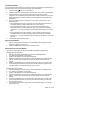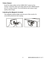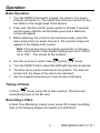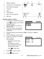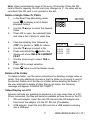
1
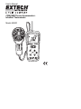
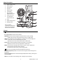
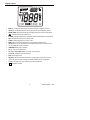
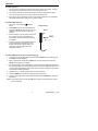
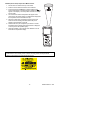
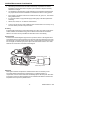
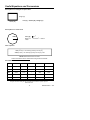
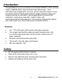
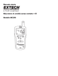
User's Guide
Pinless Moisture/Humidity Meter + IR
Model MO290
Introduction
Congratulations on your purchase of the Extech MO290 Pinless Moisture Meter with
Patented Built-in IR Thermometer. Monitor moisture in wood and other building materials with
no surface damage with the Pinless Moisture sensor (Pin-type Moisture Probe included).
Measure Humidity and Air Temperature with built-in probe plus non-contact InfraRed
Temperature with patented IR design. Advanced functions provide Grains per Pound, Dew
Point and Vapor Pressure calculations. This meter is shipped fully tested and calibrated and,
with proper use, will provide years of reliable service.
Meter Description
1.
2.
3.
4.
5.
6.
7.
8.
9.
10.
11.
12.
13.
14.
15.
16.
IR temperature sensor
Laser pointer
Humidity sensor
Temperature sensor
LCD display
Relative Humidity button
Mode/Zero Button
IR thermometer button
Alarm set button
Alarm adjust down button
ON/OFF power button
Remote pin probe input jack (bottom)
Battery compartment (rear)
Alarm adjust up button
Moisture/Relative button
Protective cap
16
1
2
3
4
5
15
14
13
12
6
7
8
9
10
11
LCD Display
1.
2.
3.
4.
5.
6.
7.
8.
9.
10.
11.
12.
13.
14.
15.
MIN MAX – Minimum and maximum value
HIGH LOW – Alarm limits
INT EXT – Internal/External probe
mBar – Vapor pressure
kPa – Vapor pressure
GPP – Grains per Pound
g/kg – Grains per kilogram
MOIST – Moisture mode
RH% - Relative Humidity mode
COND – Condensation mode
APO – Auto power off
DEW – Dew Point temperature
C/F – Temperature units
- Low battery
- Laser pointer On
2
MO290 V3.1 03/10
Safety
•
Use extreme caution when the laser pointer beam is on
•
Do not point the beam toward anyone's eye or allow the
beam to strike the eye from a reflective surface
•
Do not use the laser near explosive gases or in other
potentially explosive areas
Features
•
Quickly indicates the moisture content of materials with Pinless technology without
damaging the surface;
•
Optional remote Pin-type probe (MO290-P) allows for moisture readings at different
penetration levels (3ft/0.9m cable length);
•
Easy to read, large dual display with backlit feature;
•
Simultaneously displays % moisture of wood or material being tested and Air
Temperature, IR Temperature, or Humidity
•
Designed with patented IR design to measure non-contact surface temperature; 8:1
distance to spot ratio with 0.95 fixed emissivity
•
Built-in Humidity/Temperature probe measures Relative Humidity,
•
Air Temperature plus Grains Per Pound (GPP) and Dew Point (DP)
•
Automatic calculation of differential Temperature (IR - DP)
•
Min/Max and Data Hold
•
Auto power off and low battery indication
Battery Replacement
1.
Turn off the meter.
2.
Remove one Philips head screw and lift off the rear battery cover.
3.
Replace the 9V battery.
4.
Secure the rear battery cover.
3
MO290 V3.1 03/10
Operation
Powering the meter
1.
Remove the RH sensor protective cap before use.
2.
Press the power
3.
If the
button to turn the meter on.
symbol appears or the meter does not turn on, replace the battery.
Humidity (Dew point, GPP, g/kg) Measurements
1.
Press the power
2.
Press the RH button
button to turn the meter on.
3.
Relative Humidity will be displayed in the primary display and the temperature will be
displayed in the secondary display.
4.
Press the up or down arrow button to change the temperature units.
5.
Press the MODE button to display the DEW point.
6.
Press the MODE button to display GPP (°F) or g/kg (°C)
Pinless Moisture Measurements
1.
Press the power
2.
Press the MOIST button to select Moisture measurement.” MOIST”, and “INT”
(internal pinless sensor) will appear in the display.
button to turn the meter on.
3.
Hold the meter so that the rear sensor is away from any surface or your hand. The
reading should be near 0.0. If not, press and hold the ZERO button for more than 2
second and the ZERO icon appears.
4.
Place the rear sensor on the surface of the material to be tested and read the relative
moisture content.
Pin Type Moisture Measurements
1.
Connect the external pin probe to the jack on the bottom of the meter.
2.
Press the power
3.
Press the MOIST button twice to select Moisture measurement.” MOIST”, and “EXT”
(external pin probe) will appear in the display.
4.
Press the probe pins into the material and read the % moisture content in the display.
button to turn the meter on.
4
MO290 V3.1 03/10
Infrared Temperature Measurements
1.
Press the power
button to turn the meter on.
2.
Press the IRT button to enable the IR thermometer and the laser pointer. The laser
pointer icon will flash while the mode is active.
3.
Press the up or down arrow button to change the temperature units
4.
Aim the laser pointer at the surface to be measured and read the surface temperature
in the secondary display.
5.
Release the IRT button. The last temperature measured and the laser icon will remain
on the display for approximately 10 seconds before returning to ambient temperature
measurement.
IRT MAX MIN display:
The meter can be set to display only the maximum or minimum temperature measured
during an IR scan.
1.
With the meter in the IR hold mode, press the MODE button. “MIN” will appear in
the display.
2.
Press the IRT button to enable the IR thermometer. The meter will display the
minimum temperature measured and will update only when a lower temperature is
measured.
3.
Press the MODE button twice to enable the MAX mode and proceed as stated
above for the maximum temperature.
4.
The MAX or MIN temperature is not stored when the function is exited.
IR Field of View
Ensure that the desired target is larger than the spot size. As the distance from an object
increases, the spot size of the area measured by the meter becomes larger. The meter’s
field of view ratio is 8:1, meaning that if the meter is 8 inches (cm) from the target, the
diameter (spot) of the object under test must be at least 1 inch (cm). Refer below to the
field of view diagram.
2” @ 16”
1”
20mm
@ 8”
@ 160mm
40mm @ 320mm
WARNING: Do not directly view or direct the laser pointer at an eye. Low power
visible lasers do not normally present a hazard, but may present some potential for
hazard if viewed directly for extended periods of time.
5
MO290 V3.1 03/10
Condensation Mode
The Condensation feature alerts the used when the surface temperature as measured by the
IR thermometer is close to or has reached the Dew Point temperature.
1.
2.
3.
4.
5.
button to turn the meter on.
Press the power
Simultaneously press the MOIST/REL and RH buttons. The “COND” icon will appear.
Point the meter at a surface, press the IRT button to measure the surface
temperature. The small display will indicate the IR surface temperature and the large
display will indicate the difference between the IR temperature and the Dew Point
temperature.
The meter will then report the potential for condensation on that surface in the
following manner
• If the temperature of the IRT is more than 14°C (25°F) above the Dew Point, the
temperature difference shall be displayed, with no other warning.
• If the temperature of the IRT is 3-14°C (5-25°F) above the Dew Point, the
temperature difference shall be displayed, along with a standard Condensation
Indicator icon. The meter shall beep once to confirm that the reading is in the risk
area.
• If the temperature of the IRT is less than 3°C (5°F) above the Dew Point, the
temperature difference shall be displayed, along with a flashing Condensation
Indicator icon. The meter shall beep twice to confirm that the reading is in the highrisk area.
Press the RH button to exit the mode.
Vapor Pressure Mode
1.
2.
With the Condensation mode active, press the MODE button to display the Vapor
Pressure in mBAR (°F) or kPa (°C).
Press the MODE button to exit the Vapor Pressure mode.
Alarm High and Low Limit Setting
High and Low alarm points can be set for Humidity and Moisture measurements.
Humidity Alarm Set Procedure:
1. With RH% displayed, simultaneously press the RH and MODE buttons.
2. The “HIGH” icon will appear on the display.
3. Press the ▲or ▼button to set the high limit desired.
4. Press the ALARM SET button to save the value and proceed to the LOW set value.
5. With the “LOW” icon in the display, Press the ▲or ▼button to set the low limit
desired.
6. Press the ALARM SET button to save the value and to return to the normal mode.
7. If the humidity measurement is lower than the low alarm setting or higher than the
high alarm setting, the meter will beep once every second.
Moisture Alarm Set Procedure:
1. With MOIST displayed, simultaneously press the MOIST/REL and MODE buttons.
2. The “HIGH” icon will appear on the display.
3. Press the ▲or ▼button to set the high limit desired.
4. Press the ALARM SET button to save the value and proceed to the LOW set value.
5. With the “LOW” icon in the display, Press the ▲or ▼button to set the low limit
desired.
6. Press the ALARM SET button to save the value and to return to the normal mode..
7. If the moisture measurement is higher than the LOW alarm setting, the meter will
beep once every second
8. If the moisture measurement is higher than the HIGH alarm setting, the meter will
beep continuously.
6
MO290 V3.1 03/10
Auto Power Off
The meter will enter a sleep mode after 30 minutes of inactivity. The meter will emit a warning
beep 15 seconds before shutting down.
To disable the APO feature, press the MODE button when turning the meter ON. The “APO”
icon will not appear, indicating it is disabled.
Specifications
Function
Range
Accuracy
Pinless Moisture
0 to 99.9
Relative only
Ext. Pin Moisture
0 to 99.9
Relative only
Pinless Depth
Up to 0.75” (19mm)
RH Measurement
0 to 10%
± 3%RH
11 to 90%
± 2.5%RH
91 to 100%
± 3%RH
Air Temperature
-20 to 170°F (-29 to 77°C)
± 3.6°F (2.0°C)
IR Temp
-4 to 31°F
± 9°F
32°F
± 2°F
33 to 392°F
Greater of ±3.5% or ±9°F
-20 to-1°C
± 4.5°C
Display
Vapor Pressure
Dew Point
Mixing Ratio
Sample Rate
Backlight
Operating Temperature
Storage Temperature
Operating Humidity
Storage Humidity
Power Supply
Battery Life
Auto Power Off (APO)
APO Quiescent Current
Dimensions
Weight
0°C
± 1°C
1 to 200°C
Greater of ±3.5% or ± 4.5°C
3-digit primary display, 4-digit secondary display
0 to 20.0kPA
-22 to 199°F (-30 to 100°C)
0-999GPP (0 to 160g/kg)
2 per second
White LED
40 to 110°F (4 to 43°C)
-14 to 140°F (-30 to 60°C)
90%, 32-86°F (0-30°C), 75%, 86-104°F (30-40°C),
45%, 104-122°F (40-50°C)
90%
9V battery
6-8 weeks (4 hrs/day use), using alkaline batteries
After 30 minutes (nominal) inactivity. The APO function can be
disabled by the user.
50µA maximum
6.5x2.8x1.5’ (165x70x38mm)
7.4oz (210g)
7
MO290 V3.1 03/10
Warranty
EXTECH INSTRUMENTS CORPORATION (A FLIR COMPANY) warrants this instrument to
be free of defects in parts and workmanship for one year from date of shipment (a six
month limited warranty applies to sensors and cables). If it should become necessary to
return the instrument for service during or beyond the warranty period, contact the
Customer Service Department at (781) 890-7440 ext. 210 for authorization or visit our
website www.extech.com for contact information. A Return Authorization (RA) number
must be issued before any product is returned to Extech. The sender is responsible for
shipping charges, freight, insurance and proper packaging to prevent damage in transit.
This warranty does not apply to defects resulting from action of the user such as misuse,
improper wiring, operation outside of specification, improper maintenance or repair, or
unauthorized modification. Extech specifically disclaims any implied warranties or
merchantability or fitness for a specific purpose and will not be liable for any direct, indirect,
incidental or consequential damages. Extech's total liability is limited to repair or
replacement of the product. The warranty set forth above is inclusive and no other
warranty, whether written or oral, is expressed or implied.
Calibration and Repair Services
Extech offers repair and calibration services for the products we sell. Extech also
provides NIST certification for most products. Call the Customer Care Department for
information on calibration services available for this product. Extech recommends that
annual calibrations be performed to verify meter performance and accuracy.
Support line (781) 890-7440
Technical Support: Extension 200; E-mail: [email protected]
Repair & Returns: Extension 210; E-mail: [email protected]
Product specifications subject to change without notice
For the latest version of this User Guide, Software updates, and other
up-to-the-minute product information, visit our website: www.extech.com
Extech Instruments Corporation, 285 Bear Hill Road, Waltham, MA 02451
Copyright © 2009 Extech Instruments Corporation (a FLIR company)
All rights reserved including the right of reproduction in whole or in part in any form.
8
MO290 V3.1 03/10
User's Manual
CFM/CMM Thermo Anemometer +
InfraRed Thermometer
Model AN200
cf m/cmm
Anemometer
Thermometer
AN200
UNITS
NEXT
AREA
PROBE
TEMPERATURE
RECALL
Introduction
Congratulations on your purchase of the Extech AN200 CFM/CMM Thermo Anemometer
with InfraRed Thermometer. This instrument measures Air Velocity, Air Flow (volume),
Air Temperature (with probe) and Surface Temperature (with the InfraRed function). The
large, easy-to-read backlit LCD includes primary and secondary displays plus numerous
status indicators. The InfraRed feature includes a laser pointer for convenient targeting.
In addition, the meter can store 16 area setting dimension for easy recall. Proper use of
this meter will provide years of reliable service.
CAUTIONS
•
Improper use of this meter can cause damage, shock, injury or death. Read and
understand this user manual before operating the meter.
•
Inspect the condition of the probe and the meter itself for any damage before
operating the meter. Repair or replace any damage before use.
•
If the equipment is used in a manner not specified by the manufacturer, the protection
provided by the equipment may be impaired.
•
This device is not a toy and must not reach children’s hands. It contains hazardous
objects as well as small parts that the children could swallow. In case a child
swallows any of them, please contact a physician immediately
•
Do not leave batteries and packing material lying around unattended; they can be
dangerous for children if they use them as toys
•
In case the device is going to be unused for an extended period of time, remove the
batteries to prevent them from draining
•
Expired or damaged batteries can cause cauterization on contact with the skin.
Always, therefore, use suitable hand gloves in such cases
•
See that the batteries are not short-circuited. Do not throw batteries into the fire.
•
Do not directly view or direct the laser pointer at an eye. Low power visible lasers
do not normally present a hazard, but may present some potential for hazard if
viewed directly for extended periods of time
2
AN200-EU-ENG V2.1 3/08
Specifications
Air Velocity
Range
Resolution
Accuracy
m/s (meters per sec)
0.40 - 30.00 m/s
0.01 m/s
± (3%rdg + 0.20 m/s)
km/h (kilometers/hour)
1.4 - 108.0 km/h
0.1 km/h
± (3%rdg + 0.8 km/hr)
ft/min (feet per minute)
80 – 5900 ft/min
1 ft/min
± (3%rdg + 40 ft/m)
mph (miles per hour)
0.9 – 67.0 mph
0.1 mph
± (3%rdg + 0.4 MPH)
knots (nautical MPH)
0.8 to 58.0 knots
0.1 knots
± (3%rdg + 0.4 knots)
Range
Resolution
Area
.1
0 to 999.9m
Air Flow
CMM (cubic meters/min)
CFM (cubic ft/min)
Air Temperature
3
0-999999 m /min
3
0-999999 ft /min
Range
o
InfraRed Temperature
.1
o
0 to 999.9ft
2
2
Resolution
Accuracy
o
4.0 F (2.0 C)
o
o
14 - 140 F (-10 - 60 C)
0.1 F/C
Range
Resolution
Accuracy
o
±9.0 F (5.0 C)
1 F/C
±2% reading or ±4 F
o
(2 C) whichever is
greater
o
o
-58 to -4 F (-50 to -20 C)
o
o
-4 to 500 F (-20 to 260 C)
0.1 F/C
o
o
o
o
Circuit
Display
Sampling rate
Custom LSI microprocessor circuit
Dual function 0.5" (13 mm) 4-digit LCD
1 reading per second approx.
Sensors
Air velocity/flow sensor: Conventional angled vane arms with
low-friction ball bearing.
Temperature sensors: NTC-type precision thermistor and
InfraRed
6 to 14µm
0.95 fixed
8:1
2.5 readings per second approx.
Auto shut off after 20 minutes to preserve battery life
32°F to 122°F (0°C to 50°C)
o
o
14 to 140 F (-10 to 60 C)
<80% RH
<80% RH
2000 meters (7000ft) maximum
One 9 volt (NEDA 1604) battery
IR Spectral response
IR Emissivity
IR distance ratio
IR sampling rate
Automatic Power off
Operating Temperature
Storage Temperature
Operating Humidity
Storage Humidity
Operating Altitude
Battery
Battery life
Battery current
Weight
Dimensions
80 hours approx. (if Backlight and Laser are used continuously
the battery life is reduced to 2 to 3 hours approx.)
8.3 mA DC approx.
1.6 lbs. (725g) including battery & probe
Main instrument: 7.0 x 2.9 x1.2" (178 x 74 x 33mm)
Sensor Head: 2.75” (70mm) Diameter
3
AN200-EU-ENG V2.1 3/08
Meter Description
1.
Power ON/OFF button
2.
Probe input jack
3.
Laser pointer
4.
IR Sensor
5.
Rubber holster
6.
LCD Display
7.
IR thermometer
measurement button
8.
Airflow buttons (4)
9.
Air Temperature
function buttons (2)
10. Vane
11. Airflow Average button
12. Backlight button
Note: The battery
compartment, tilt stand and
tripod mount are located on
the rear of the instrument
Keypad
•
Press to turn the meter ON or OFF
• IR + Laser Pointer Press and hold to measure.
• MAX/MIN Record and store the highest and lowest airflow or velocity readings.
◄ (LEFT) also serves as change decimal point button in AREA mode
• UNITS Press to select the mode of operation. In FLOW mode, the meter displays air
volume. In VELOCITY mode, the meter displays air speed.
▲ (UP) also serves as increase number button in AREA mode.
• HOLD Press to freeze the displayed reading. Press again to unlock display.
►(RIGHT) also serves as change digit button in AREA mode.
• AREA Press and hold to manually enter the area of a duct in CFM or CMM mode.
Press and hold to scroll thru memory locations.
This button also clears memory in the Averaging mode.
•
Press to turn the backlight on/off. Hold to disable Auto Power Off.
• MAX/MIN (Temperature) Press to record and store the highest, lowest readings for air
temperature.
•
•
HOLD (Temperature) Press to freeze the displayed temperature reading. Press again to
unlock the display.
AVG Press and hold to enter averaging mode. Averages up to 20 readings.
4
AN200-EU-ENG V2.1 3/08
Display Layout
•
MAX (top of LCD): Max Hold function engaged for the Air Temperature function
•
HOLD (top of LCD): Data Hold function engaged for the Air Temperature function
•
PROBE TEMP: Reminder that the top LCD digits represent Air (Vane) Temperature
•
: Indicates that the laser pointer is on.
•
IR TEMP: Indicates that the larger LCD digits represent IR temperature measurement
•
VEL: indicates that meter is in air velocity mode
•
FLOW: indicates that meter is in air flow mode
•
MAX (bottom of LCD): Max Hold for the IR Temperature and RH function
•
HOLD (bottom of LCD): Data Hold for the IR Temperature function and RH function
•
o
•
CFM/CMM: airflow units of measure
•
Ft , m : units for area dimensions
•
m/s, ft/min, km/h, MPH, knots: air velocity units of measure
o
C / F: Temperature units of measure
2
2
•
X10, X100: multipliers for air flow readings
•
AVG: air averaging mode
•
RECORD: indicates that min/max function is running (top for temp, bottom for air)
•
Large LCD digits at center of display for Relative Humidity and IR Temperature
•
Smaller LCD digits at top, right of display for Probe Temperature
•
: Low battery indicator
5
AN200-EU-ENG V2.1 3/08
Operation
Connecting the Vane
1. The vane plug is inserted in the meter’s sensor jack at the top of the meter. The plug
and jack are keyed so that the plug can only fit in the jack one way.
2. Turn the plug carefully until it lines up with the jack and then firmly push the plug in
place. Do not apply undue force or try to twist the plug side-to-side.
3. If the vane is not connected to the meter or if the sensor is defective, the LCD display
will indicate dashed lines in place of an air velocity reading.
Air Velocity Measurements
1. Turn on the meter using the
button.
ON/OFF
2. Press UNITS button to select the desired unit
of measure. NOTE: At power up the meter will
display the last unit of measure previously
entered.
Side view of Vane
Arrow
3. Place the sensor in the air stream. Ensure that
the air enters the vane as indicated by the
arrow sticker placed inside the vane. Refer to
the diagram.
airflow
4. View the air velocity and temperature readings
on the LCD Display. The large main LCD
display shows the Air Velocity reading. The
upper right LCD sub-display shows the
temperature reading.
Air Velocity Measurements (Up to 20 Point averaging)
1. To enter 20 Point Averaging Mode, press and hold the AVG button until it beeps twice.
The AVG icon will be displayed.
2. Take a measurement and press the AVG button. A single beep will sound and the
HOLD icon will appear in the display.
3. The average reading will be displayed and number of readings measured will appear in
the upper right hand corner of the display. After 5 seconds, the display will return to the
current reading. (IMPORTANT: Please note that the average readings are only held for
5 seconds and cannot be recalled.)
4. Repeat steps 2 - 3 until all desired points have been measured.
5. Press the AREA button to clear the multipoint averaging memory.
6. To return to standard velocity measuring mode press and hold AVG button until meter
beeps twice.
Note: In AVG mode, press and hold the AVG button until the meter beeps twice to return
to normal operation.
6
AN200-EU-ENG V2.1 3/08
Air Flow Measurements (CMM / CFM)
1.
Turn on the meter using the
2.
Press the UNITS button to select the desired air
flow units: CMM (cubic meters per minute) or
CFM (cubic feet per minute). NOTE: At power up
the meter will display the last unit of measure
previously entered.
3.
4.
ON/OFF button
2
Side view of Vane
Arrow
2
To begin entering the area in m or ft , press and
hold the AREA button until it beeps twice. The
leftmost digit of the bottom display will begin to
flash.
airflow
Use the ▲ (UP) button to change the flashing
digit
Use the ◄ (LEFT) button to move the decimal
Use ► (RIGHT) button to select the other digits.
After all of the digits are entered, press and hold
the AREA button (until meter beeps twice) to
save the area into memory and return to CFM or CMM measuring mode.
5.
Place the sensor in the air stream. Ensure that the air enters the vane as indicated by
the arrow sticker placed inside the vane. Refer to the diagram.
The meter has 16 memory locations (8 for CFM and 8 for CMM) that can be used to storel
commonly used area sizes that you can recall at anytime.
1.
Press the AREA button until meter beeps twice. A memory location number will
appear in the top right of the display indicating the memory location.
2.
Push the AREA button to scroll thru and select the desired location. Once you have
selected the desired memory location enter your dimension
Use the ▲ (UP) button to change the flashing digit
Use the ◄ (LEFT) button to move the decimal
Use ► (RIGHT) button to select the other digits. After all of the digits are entered,
press and hold the AREA button (until it beeps twice) to save the area into memory
and return to CFM or CMM measuring mode.
To select and use a previously stored dimension, press and hold the AREA button until it
beeps twice.
Press AREA to scroll thru the 8 memory locations. Press and hold the AREA button until it
beeps twice. to return to CFM or CMM measuring mode.
Air Flow Measurements (Up to 20 Point averaging)
1. To enter 20 Point Averaging Mode, press and hold the AVG button until it beeps twice.
The AVG icon will be displayed.
2. Take a measurement and press the AVG button. A single beep will sound and the
HOLD icon will appear in the display.
3. The average reading will be displayed and number of readings measured will appear in
the upper right hand corner of the display. After 5 seconds, the display will return to the
current reading. (IMPORTANT: Please note that the average readings are only held for
5 seconds and cannot be recalled.)
4. Repeat steps 2 - 3 until all desired points have been measured.
5. Press the AREA button to clear the multipoint averaging memory.
6. To return to standard airflow measuring mode press and hold AVG button until meter
beeps twice.
AN200-EU-ENG V2.1 3/08
7
Data Hold (Air Velocity/Air Flow)
1. While taking measurements, press the HOLD button to freeze the air velocity/air flow
reading for later viewing.
2. The HOLD indicator will appear in the bottom of the LCD display.
3. Press HOLD again to return to normal operation.
MAX/MIN/AVG Record (Air Velocity/Air Flow)
This allows the user to record and view the highest (MAX), lowest (MIN) and average
(AVG) readings.
1. Press the button MAX/MIN button. The AVG indicator and RECORD indicator along
with the average reading will appear on the LCD display and the meter will begin
keeping track of the MAX, MIN and Average values.
2. Press the MAX/MIN button again. The MAX indicator will appear on the display and
display the Max reading.
3. Press the MAX/MIN button again to view the minimum reading. The MIN indicator
along with the minimum reading will appear on the LCD display and display the Min
reading.
4. Press the MAX/MIN button again to display current readings. NOTE: the meter will
keep recording MAX/MIN/AVG readings.
5. To clear and stop MAX/MIN/AVG recording and return to normal operation, press the
AREA button once when displaying the current reading.
8
AN200-EU-ENG V2.1 3/08
Temperature Units
1. Remove the meter’s rubber protective jacket and select the desired temperature units
using the °F/°C slide switch located in the battery compartment.
2. Replace the protective jacket and connect the sensor to the sensor input jack on top of
the meter.
Data Hold (Air Temperature)
1. While taking measurements, press the PROBE TEMPERATURE HOLD button to
freeze the air temperature reading.
2. The HOLD indicator will appear in the bottom of the LCD display.
3. Press PROBE TEMPERATURE HOLD again to return to normal operation.
Max/Min Record (Air Temperature)
This allows the user to record and view the highest (MAX), lowest (MIN) air temperature
readings.
1. Press the TEMPERATURE MAX/MIN button once. The MAX indicator will appear on
the display and the meter will begin keeping track of the MAX/MIN air temperature
values.
2. Press the button again to view the minimum reading. The MIN indicator along with the
minimum air temperature reading will appear on the LCD display.
3. Press the button again to return to normal operation.
Automatic Power OFF
To conserve battery life, the meter automatically turns off after 20 minutes. To override this
feature:
1. Turn the meter OFF.
2. Press and hold the
(Backlight) key while turning the meter ON.
3. “dis APO” will appear in the display. The AUTO POWER OFF feature will now be
disabled.
4. Note that AUTO POWER OFF is re-enabled each time the meter is turned on.
5. Also note that AUTO POWER OFF is disabled in CFM/CMM or Average mode.
9
AN200-EU-ENG V2.1 3/08
InfraRed (Non-Contact) Temperature Measurements
1. The IR sensor is located at the top of the meter.
2. Point the sensor toward the surface to be measured.
3. Press and hold the red IR button to begin measuring the
surface temperature of a desired target. IR TEMP and
will
appear on the display. The laser pointer will switch on to help
aim the meter.
4. The measured IR surface temperature will appear at the
center of the LCD (larger digits). The temperature displayed is
the temperature of the area within the spot.
5. When the red IR button is released, the laser pointer will
switch off and the reading will freeze (data hold) on the
display for approximately 3 seconds.
6. Note that the vane (Air Temperature) continues to monitor
temperature during IR tests and its temperature is displayed
on the top of the LCD (smaller digits).
7. After approximately 3 seconds the meter defaults to the Air
Flow and Air Temperature display.
WARNING: Do not directly view or direct the laser pointer at an eye. Low power
visible lasers do not normally present a hazard, but may present some potential for
hazard if viewed directly for extended periods of time.
10
AN200-EU-ENG V2.1 3/08
Battery Replacement
When
appears on the LCD, the 9V battery must be replaced.
1. Disconnect the vane.
2. Remove the meter’s rubber protective jacket
3. Use a flat blade screwdriver or a coin to open the rear battery compartment
4. Replace the 9V battery
5. Close the battery compartment and replace the meter’s protective jacket
You, as the end user, are legally bound (Battery ordinance) to return all used
batteries and accumulators; disposal in the household garbage is prohibited!
You can hand over your used batteries / accumulators, gratuitously, at the
collection points for our branches in your community or wherever batteries /
accumulators are sold!
Disposal
Follow the valid legal stipulations in respect of the disposal of the device at the
end of its lifecycle
11
AN200-EU-ENG V2.1 3/08
InfraRed Measurement Considerations
•
When taking IR measurements the meter automatically compensates for ambient
temperature changes. Note that it may take up to 30 minutes to adjust to extremely
wide ambient changes.
•
Low temperature measurements quickly followed by high temperature measurements
may require several minutes to stabilize as a result of the IR sensor cooling process.
•
If the surface of the object under test is covered with frost, oil, grime, etc., clean before
taking measurements.
•
If an object's surface is highly reflective apply masking tape or flat black paint before
measuring.
•
Steam, dust, smoke, etc. can obstruct measurements.
•
To find a hot spot, aim the meter outside the area of interest then scan across (in an up
and down motion) until the hot spot is located.
IR Theory
IR thermometers measure the surface temperature of an object. The meter’s optics sense
emitted, reflected, & transmitted energy that is collected and focused onto the meter’s
detector. The meter’s circuitry translates this information into an LCD reading.
IR Field of View
Ensure that the desired target is larger than the spot size as shown in the diagram below.
As the distance from an object increases, the spot size of the area measured by the meter
becomes larger. The meter’s field of view ratio is 8:1, meaning that if the meter is 8 inches
from the target, the diameter (spot) of the object under test must be at least 1 inch. Other
distances are shown below in the field of view diagram.
Distance to Object in inches
10”
8”
1”
1.25”
Diameter of Spot in inches
12”
1.5”
Emissivity
Most organic materials and painted or oxidized surfaces have an emissivity of 0.95.
Inaccurate readings will result when measuring shiny or polished surfaces. To
compensate, cover the surface under test with masking tape or flat black paint. Allow time
for the tape to reach the same temperature as the material underneath then measure the
temperature of the tape or the painted surface.
12
AN200-EU-ENG V2.1 3/08
Thermal Emissivity Table for Common Materials
Material
Emissivity
Cloth (black)
0.98
Asphalt
0.90 to 0.98
Human skin
0.98
Concrete
0.94
Leather
0.75 to 0.80
Cement
0.96
Charcoal (powder)
0.96
Sand
0.90
Lacquer
0.80 to 0.95
Earth
0.92 to 0.96
Lacquer (matt)
0.97
Water
0.67
Rubber (black)
0.94
Ice
0.96 to 0.98
Plastic
0.85 to 0.95
Snow
0.83
Timber
0.90
Glass
0.85 to 1.00
Paper
0.70 to 0.94
Ceramic
0.90 to 0.94
Chromium oxides
0.81
Marble
0.94
Copper Oxides
0.78
Plaster
0.80 to 0.90
Iron Oxides
0.78 to 0.82
Mortar
0.89 to 0.91
Textiles
0.90
Brick
0.93 to 0.96
13
AN200-EU-ENG V2.1 3/08
Useful Equations and Conversions
Area equation for rectangular or square ducts
Height (H)
Area (A) = Width (W) x Height (H)
Width (W)
Area equation for circular ducts
Area (A) = 6 x r2
Where 6 = 3.14 and r2 = radius x
radius
Radius
Cubic equations
CFM (ft3/min) = Air Velocity (ft/min) x Area (ft2)
CMM (m3/min) = Air Velocity (m/sec) x Area (m2) x 60
NOTE: Measurements made in inches
must be converted to feet or meters before using the above formulae.
Unit of Measure Conversion Table
m/s
ft/min
knots
km/h
MPH
1
196.87
1.944
3.6
2.24
1 ft/min
0.00508
1
0.00987
0.01829
0.01138
1 knot
0.5144
101.27
1
1.8519
1.1523
1 km/h
0.2778
54.69
0.54
1
0.6222
1 MPH
0.4464
87.89
0.8679
1.6071
1
1 m/s
Copyright © 2008 Extech Instruments Corporation
All rights reserved including the right of reproduction in whole or in part in any form.
www.extech.com
14
AN200-EU-ENG V2.1 3/08
User's Guide
Video Borescope
Models BR200 and BR250
Introduction
Congratulations on your purchase of this Extech BR200 (17mm camera
head) or BR250 (9mm camera head) Video Borescope. This
instrument was designed for use as a remote inspection device. It can
be used to peer into tight spots and then supply real-time video and
images that can be recorded. Typical applications include HVAC
inspection, automotive inspection, cable routing, and
automotive/boat/aircraft inspection. This meter is shipped fully tested
and, with proper use, will provide years of reliable service.
Features
•
•
•
•
•
3.5 '' TFT-LCD palm LCD monitor with high resolution
The image head and the cable are water resistant when the
unit is fully assembled (the monitor and the camera are not
water resistant)
Wireless and hard-wired functionality
The monitor records video and images
SD card capacity: 16G
Safety
•
•
•
•
Do not expose instrument to moisture
Shut off the instrument when not in use
Remove the batteries when cleaning the instrument
Replace all batteries at the same time
2
BR200-BR250-EU-EN-V7.0 5/11
Supplied Equipment
1.
Camera
2.
LCD Monitor
3.
Monitor Adaptor
4.
Adaptor cable
5.
Accessory Magnet / Hook / Mirror
6.
Magnetic mount
7.
Flex cable and camera head
8.
4 AA Batteries
1
2
4
5
7
8
3
3
6
BR200-BR250-EU-EN-V7.0 5/11
Description
1
Signal output
2
Power Indicator
3
Power On/Off, Dimmer
4
Flexible tube
5
Camera head and LED’s
6
OK
7
Up, video or jpg
8
Menu
9
1
2
3
4
Down. Channel select (4)
5
10 Power On/Off
6
7
8
9
11 Power Indicator
12 USB Socket
13 Video output
14 SD card socket
10
15 Power supply socket
16 Reset
11
17 Signal input
12
13
14
15
16
17
4
BR200-BR250-EU-EN-V7.0 5/11
Installation
Install the batteries into the instrument body, charge the monitor battery,
connect the camera and flexible tube to the body, insert the micro SD
card. Install any accessory as needed.
Battery Installation
Connect Monitor Power
The monitor has a rechargeable battery. Plug in the AC adaptor and
connect the cable to the DC5V socket on the monitor. The power
indicator will light in red (or the battery capacity icon on LCD of
monitor will blink, indicating that it is charging - and will turn off after
a full charge)
Connect the camera and flexible tube
Connect the camera tube to the instrument body; ensure that the keyed
ends are properly aligned. Once aligned, tighten the knurled knob to
hold the connection firmly in place.
5
BR200-BR250-EU-EN-V7.0 5/11
Warning. Permanent damage to the flex tube and loss of
operation will occur if the flex tube is subjected to
narrow radius or sharp angle bends.
Inserting the micro SD card
Insert card with arrow pointing toward slot. Gently apply pressure
until card locks into the spring loaded slot. To remove from unit,
gently push the card inward and then release to eject it from the card
slot.
Installing the accessory tools (BR200)
The included accessories (mirror, hook and magnet) all attach to the
camera in the same manner. Refer to the diagrams below:
6
BR200-BR250-EU-EN-V7.0 5/11
Installing the accessory tools (BR250)
Hook the attachment into the hole in the head and then slide the
rubber sleeve over the attachment shaft
Attaching the Monitor to the instrument body
Connect the USB Cable
Use the USB cable to connect the monitor to a PC. The USB
online icon will appear on the PC. Open My Computer on the
PC, and locate the Mobile Disk. The Mobile disk can be used
and accessed in the same manner as any external hard drive.
7
BR200-BR250-EU-EN-V7.0 5/11
Video Output
Insert the video cable into the VIDEO OUT socket on the
monitor. Insert the other end of the cable into the VIDEO IN jack
of a TV or other monitor. The LCD Monitor will output a high
quality video image.
Installing the Magnetic bracket
The magnetic bracket slides onto the rear of the monitor for
convenient placement and viewing.
8
BR200-BR250-EU-EN-V7.0 5/11
Operation
Basic Operation
1. Turn the ON/OFF dial switch to power the camera. The power
indicator will switch on. The switch then acts as a dimmer for the
two LEDs on the imager head of the camera.
2. Press and hold the monitor power switch for at least 2 seconds
and the power indicator will illuminate green and a Welcome
screen will appear.
3. Before attaching the monitor to the instrument body, press the
down arrow button to select channel 4. The real time image will
appear on the display LCD monitor.
Note. If the picture does not properly syncronize or has poor
color, check that the Video System Settings are set to “NTSC”,
not to ‘PAL” . This should fix the condition..
4. Use the up arrow to select video
or photo
mode.
5. Turn the ON/OFF dial to adjust the LED light intensity as desired.
6. The tube can be easily maneuvered into position. The tube can
be bent into the shape of the area to be examined.
7. Use the supplied accessories to help retrieve small items.
Taking a Picture
In Photo
mode, press OK to take a picture. The photo will
automatically save to the SD card.
Recording a Video
In Real-Time Monitoring (video) mode, press OK to begin recording;
refer to the following diagram for display icon definitions:
9
BR200-BR250-EU-EN-V7.0 5/11
1.
Battery capacity
2.
Function icon (video/photo)
3.
Recording in progress
4.
Channel
5.
Date
6.
Time Stamp
7.
REC Time remaining
8.
SD card
1
2
3
4
CH 4
2009/07/28
11:12:31
5
6
[0]
8
7
Viewing a Photo or Video
1.
2.
3.
4.
5.
6.
In the Real-Time Monitoring mode,
press
to display a list of dated
playback folders
Use the ▼▲keys to select the
desired folder.
Press OK to open the selected
folder and view a list of photo or
video files.
Files are listed by time followed by (VID”) for photos or (VID) for
videos
Use the ▼▲keys to select a file.
Press OK to display the selected
0001/0004
2009-06-10
photo or video.
13:00:24
VID”
For video files:
13:00:24
VID”
Press OK to pause while
13:00:24
VID”
playing.
13:00:24
VID
Press again to resume.
▲ Fast Forwards the video
▼ Rewinds the video
Press
to stop video
7.
Press
to return to menu.
8.
Press
again to exit.
10
BR200-BR250-EU-EN-V7.0 5/11
Note: Video automatically saves to file every 30 minutes. When the SD
card is filled to capacity, the SD card icon changes to ‘F’. No video will be
recorded if the SD card is not inserted in the slot.
Delete a Single Video Or Photo
1.
2.
3.
4.
5.
6.
In the Real-Time Monitoring mode,
press
to display a list of dated
playback folders
Use the ▼▲keys to select the desired
folder.
Press OK to open the selected folder
and view a list of photo or video files.
Files are listed by time followed by
(VID”) for photos or (VID) for videos
Use the ▼▲keys to select a file.
8.
Press and HOLD the
button, the
display will show ‘DELETE CURRENT
FILE?’
Use the arrow keys to select YES or
NO
Press OK to accept selection.
9.
Press
7.
2009-06-10
13:00:24
VID”
13:00:24
VID”
13:00:24
VID”
13:00:24
VID
0001/0004
twice to exit the Delete screen.
Delete a File Folder
To delete a folder, use the same instructions for deleting a single video or
photo. The only additional concern is that if a folder is not empty it cannot
be deleted. Delete all of the files in a folder before deleting the folder. If
the user attempts to delete a folder that is not empty, the following
message will appear: FOLDER NOT EMPTY
Video Display on a PC
Several methods are available to playback or to copy video files on a PC.
When connected, the files will become available as new drives on the PC.
1.
SD card adaptor: Insert the mini SD card into the SD adaptor and
then insert the adaptor into the PC SD slot (if available)
2.
USB adaptor: Insert the mini SD card into a USB adaptor and plug
into a USB port.
11
BR200-BR250-EU-EN-V7.0 5/11
3.
USB cable. Connect the USB cable from the camera to the PC.
Settings Mode
Press and hold
for two seconds to enter the Settings Mode.
Language Settings
1. In Settings Mode, use the arrow keys to select SYSTEM
SETTING (green icon).
2. Press OK to call up the SYSTEM icon list
3. Use the arrow keys to highlight the Language icon (globe)
4. Press OK and the Language icon list will appear (flags)
5. Use the arrow keys to highlight the desired language
6. Press OK to select the highlighted language and exit
Video System Settings
1. In Settings Mode, use the arrow keys to select SYSTEM
SETTING (green icon).
2. Press OK to call up the SYSTEM icon list
3. Use the arrow keys to highlight the Video System icon (yellow)
4. Press OK and the Video format selections will appear (NTSC,
PAL)
5. Use the arrow keys to highlight NTSC
6. Press OK to select the highlighted format and exit
Format and Erase Media
1. In Settings Mode, use the arrow keys to select SYSTEM
SETTING (green icon).
2. Press OK to call up the SYSTEM icon list
3. Use the arrow keys to highlight the FORMAT icon (blue)
4. Press OK and the FORMAT selection screen will appear (YES,
NO)
5. Use the arrow keys to highlight the desired response
6. Press OK to accept the selection and exit
12
BR200-BR250-EU-EN-V7.0 5/11
Restoring Factory Default Settings
1. In Settings Mode, use the arrow keys to select SYSTEM
SETTING (green icon).
2. Press OK to call up the SYSTEM icon list
3. Use the arrow keys to highlight the DEFAULT icon (red)
4. Press OK and the DEFAULT selection screen will appear (YES,
NO)
5. Use the arrow keys to highlight the desired response
6. Press OK to accept the selection and exit
View Version
1. In Settings Mode, use the arrow keys to select SYSTEM
SETTING (green icon).
2. Press OK to call up the SYSTEM icon list
3. Use the arrow keys to highlight the VERSION icon (green)
4. Press OK to view the version
5. Press OK again to exit
Frame Rate Setting
1. In Settings Mode, use the arrow keys to select RECORDER
SETTING (red icon).
2. Press OK to call up the RECORDER options
3. Use the arrow keys to highlight the FPS (frames per second)
icon
4. Press OK to open the FPS parameter
5. Use the arrows to select the frame rate: 10, 15, 20, 25, or 30
6. Press OK to confirm
13
BR200-BR250-EU-EN-V7.0 5/11
Time Stamp ON OFF Setting
1. In Settings Mode, use the arrow keys to select RECORDER
SETTING (red icon).
2. Press OK to call up the RECORDER options
3. Use the arrow keys to highlight the Time Stamp icon (purple)
4. Press OK to open the parameter
5. Use the arrows to select ON or OFF
6. Press OK to confirm
Date/Time Setting
1. In Settings Mode, use the arrow keys to select DATE-TIME
SETTING (yellow icon).
2. Press OK to call up Date and Time Settings window
3. Use OK to tab through the fields
4. Use the arrow keys to change a field setting
5. Press the
button to exit
Battery Replacement
You, as the end user, are legally bound (EU Battery
ordinance) to return all used batteries, disposal in the
household garbage is prohibited! You can hand over your
used batteries / accumulators at collection points in your
community or wherever batteries / accumulators are sold!
Disposal: Follow the valid legal stipulations in respect of the
disposal of the device at the end of its lifecycle
14
BR200-BR250-EU-EN-V7.0 5/11
Troubleshooting:
Power Reset for the LCD Unit
In the event of a power failure in the BR200/250 LCD display unit,
follow the steps below to perform a power reset:
1. Un-dock the LCD module from the BR200/250 pistol-grip base
unit.
2. Connect the AC adapter to the LCD module and the appropriate
AC power source.
3. Locate the Reset port on the reverse side of the LCD module
(labeled Reset).
4. Momentarily press the Power Reset button for at least 2 seconds
and then release.
5. Leaving the AC adapter connected to the LCD module, power the
unit on.
6. If the unit powers on, allow it to fully re-charge (up to 2 hours)
before removing the AC adapter. If the LCD unit does not power
on, repeat steps 1 through 6.
Specifications
CAMERA
Imaging Sensor
Total Pixels (NTSC)
Horizontal View Angle
Transmission Frequency
Focus point
Minimum Illumination
Modulation Type
Bandwidth
Power Supply
Unobstructed Effective Range
Waterproof Capacity
Dimensions (W D H)
CMOS
BR200: 712 x 486; BR250: 640 x 480
BR200: 50 degrees
BR250: 45 degrees
2468MHz
BR200: 20cm (8”), BR250: 10cm (4”)
0 Lux
FM
18MHz
4 x AA batteries
10m
IP67 (imager head only)
186 x 145 x 41(mm) (Exclude Flexible
Tube)
15
BR200-BR250-EU-EN-V7.0 5/11
Weight (approx)
Camera head Diameter
Operating Temperature
MONITOR
LCD Screen Type
Effective Pixels
Video System
Transmission Frequency
Exterior Supply Voltage
Consumption Current (Max.)
Charge Time
Work Time
Video Output Level
Receiving Sensitivity
Dimensions (W x D x H)
Weight (Approx)
Operating Temperature
Operating Humidity (Max.)
BR200: 530g
BR250: 450g
BR200: 17mm (0.67”)
BR250: 9mm (0.36”)
-10°C~+50°C
+14°F~+122°F
3.5” TFT-LCD
320 (R.G.B.) x 240
PAL/NTSC
2414, 2432, 2450, 2468MHz
5VDC
500mA
3 hours
2 hours
0.9-1.3VP-P@75Ώ
≤-85dBm
100 x 70 x 25(mm)
140g
-10°C~+50°C
+14°F~+122°F
15~85%RH
FCC Information
This device complies with part 15 of the FCC rules.
BR250/200: FCC-ID TW5GB8802-GB8803
Operation is subject to the following two conditions:
1. This device may not cause harmful interference
2. This device must accept any interference received, including
interference that may cause undesired operation.
Copyright © 2011 Extech Instruments Corporation (a FLIR company)
All rights reserved including the right of reproduction in whole or in part in any
form.
16
BR200-BR250-EU-EN-V7.0 5/11