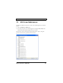
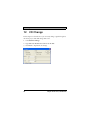
1
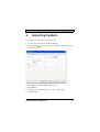
User’s Guide
Preface
Information Designer User’s Guide
Preface
Information Designer is a software application for the configuration of
CIMREX and EXTER operator terminals. Information Designer helps
you create logical, flexible, and effective HMI applications that provide the
right information on the right occasion to operators and other systems.
This manual is based on an example project that the user completes step
by step.
Information Designer also includes a Reference Manual (MA00749).
© Beijer Electronics AB, MA00750A, 2005-02
The information in this document is subject to change without notice and is provided as
available at the time of printing. Beijer Electronics reserves the right to change any information without updating this publication. Beijer Electronics assumes no resposibility for any errors that may appear in this document.
All examples in this manual are only intended to improve understanding of the functionality
and use of the software. Beijer Electronics AB cannot assume any liability if these examples
are used in actual applications.
In view of the wide range of applications for this software, users must acquire sufficient
knowledge themselves in order to ensure that the software is correctly used in their specific
application.
Beijer Electronics AB will accept no liability for any damage incurred during the installation
or use of this software.
Beijer Electronics AB prohibits all modification of the software.
Beijer Electronics, MA00750A
1
Contents
Contents
1 Introduction..................................................................................... 4
1.1 Manual Structure ....................................................................... 4
2 Installing and Starting the Program.................................................. 5
2.1 System Requirements ................................................................. 5
2.2 Installing the Configuration Tool............................................... 6
2.3 Starting the Configuration Tool ................................................. 6
3 Creating a New Project .................................................................... 7
3.1 Select File/New... ....................................................................... 7
3.2 Open the Block Manager ........................................................... 8
3.3 Save the Project .......................................................................... 8
3.4 Add Object................................................................................. 9
4 Starting the Simulator .................................................................... 12
5 Creating Jumps between Blocks ..................................................... 13
5.1 Add a Block.............................................................................. 13
5.2 Open the Main Block............................................................... 14
5.3 Create a Jump back to the Main Block ..................................... 14
6 Importing Symbols ........................................................................ 15
7 Adding a Trend Object .................................................................. 17
7.1 Test run the Project.................................................................. 18
8 Alarm Management........................................................................ 19
8.1 Create a Jump back to the Alarm Block.................................... 20
8.2 Create an Object to Activate the Alarm .................................... 20
8.3 Test run the Project.................................................................. 21
9 Create a Recipe Block .................................................................... 22
9.1 Copy Object............................................................................. 24
9.2 Create a Series .......................................................................... 25
9.3 Create Functions to Load and Save Recipes.............................. 25
10 Report Printouts ............................................................................ 27
10.1Print the Report Block ............................................................ 28
11 I/O Cross Reference....................................................................... 29
2
Beijer Electronics, MA00750A
Contents
12 I/O Change.................................................................................... 30
13 Test the Project .............................................................................. 31
14 Dual Drivers .................................................................................. 32
14.1Data Exchange between Controllers........................................ 32
15 The Terminal as an FTP Server...................................................... 33
15.1Activate FTP Server ................................................................ 33
Beijer Electronics, MA00750A
3
Introduction
1
Introduction
The Information Designer configuration tool is a software package for the
development of projects for the CIMREX and EXTER operator terminals.
The HMI system is supplied with all the basic functions you could possibly
need for your application. The functions are well tested and have been
developed with customer needs and preferences in focus.
The configuration tool can be used to easily create a complete process image with the aid of pre-defined objects. In this way, it is easy to gain an
overview of a complex application. Users can also customize the predefined objects or create their own.
Communication drivers for most controllers and automation equipment
on the market are available.
1.1
Manual Structure
This manual is based on examples, which makes it easy to get started with
program development with Information Designer. The idea behind the
manual is that the reader follows the instructions from the start to finally
produce a functioning project that can be further developed or used for
ideas. The examples are shown in an operator terminal with touch display.
It is assumed that the user has good knowledge of Windows and access to
documentation for the Windows 2000/XP operating system. For information about the use of the configuration tool, refer to the help files (press
F1) and the Reference Manual for EXTER.
4
Beijer Electronics, MA00750A
Installing and Starting the Program
2
Installing and Starting the
Program
For ease of use, we recommend using a mouse with the configuration tool.
For keyboard commands, refer to the manual for Windows 2000/XP
Professional.
The help text for the current function in the program is obtained by
pressing the F1 key.
2.1
System Requirements
Hardware and Software
Operating System
Recommended
Windows 2000 Professional
Windows XP Professional
Processor
Pentium II, 266 MHz
RAM
64 MB
Free space on hard drive
100 MB
Installed software
Internet Explorer 5.0 or later
The configuration tool ought to be used on a color monitor with more
than 256 colors.
Beijer Electronics, MA00750A
5
Installing and Starting the Program
2.2
Installing the Configuration Tool
The configuration tool is supplied on a CD. The manuals can also be read
from the CD.
The installation creates an icon for the configuration tool in the
Information Designer program group.
2.3
Starting the Configuration Tool
Once the configuration tool is installed, you can start it by selecting
Information Designer under Start/All Programs/Information Designer.
The first time the configuration tool is started, the Project Manager is
shown together with certain toolbars.
6
Beijer Electronics, MA00750A
Creating a New Project
3
3.1
Creating a New Project
Select File/New...
Select File/New... to create a new project. Select Operator Terminal and
Controller systems. Click OK. The project is named the first time it is
saved.
When a new project is created, a tree structure for the project (Project
Manager), various menus, toolbars, and object palettes are shown.
Beijer Electronics, MA00750A
7
Creating a New Project
3.2
Open the Block Manager
In the manual, we will use the block manager as the starting point when
creating our project. Select View/Block Manager to activate the block
manager.
3.3
Save the Project
Save the project by clicking the diskette symbol or select File/Save as....
Specify a name for the project and the save destination. In this case, name
the project User_guide. Finish by clicking Save.
8
Beijer Electronics, MA00750A
Creating a New Project
3.4
Add Object
1. Double-click Main in the block manager. The main block is opened.
2. Select the Speedometer
object in the object palette and click in
the block. The properties dialog for the object now opens.
3. Type D0 in the Analog signal field on the General tab.
4. Click OK.
The object is now shown in the block. Drag the handles to resize and
position the object as desired.
Beijer Electronics, MA00750A
9
Creating a New Project
When, for example, adding objects or drawing graphics in the work area,
the Undo function in the Edit menu can be used (10 steps). The keyboard
shortcut Ctrl+Z can also be used.
5. Now add a slider by selecting the Slider
palette and click in the block.
object in the object
6. Type D0 in the Analog signal field on the General tab.
Note:
On the Access tab, the Enable operator input function must be
checked in order to be able to maneuver the object.
7. Click OK.
10
Beijer Electronics, MA00750A
Creating a New Project
Beijer Electronics, MA00750A
11
Starting the Simulator
4
Starting the Simulator
The Simulator is used to test run the project on a personal computer. Save
the project and click the Play button
or select Project/Run. Now, a new
window is shown, acting as the operator terminal.
You can now drag the slider to see how the speedometer changes.
Press Esc to end the simulator and return to the configuration tool.
12
Beijer Electronics, MA00750A
Creating Jumps between Blocks
5
Creating Jumps between Blocks
This chapter describes how to create jumps between the different blocks in
the project.
5.1
Add a Block
1. Right-click in the block manager and select New Block. Type a name
for the block, in this case Block1, and click OK. The block is now
opened.
2. Press and hold the left mouse button with the pointer located in the
main block in the block manager and drag an arrow to Block1. A
jump is now created to the new block.
Block1 is now found in the block manager, as shown.
Beijer Electronics, MA00750A
13
Creating Jumps between Blocks
5.2
Open the Main Block
3. Double-click the main block in the block manager.
A button has now been automatically created for a jump to Block1.
5.3
Create a Jump back to the Main
Block
Create a jump back to the main block by dragging an arrow from Block1
to the main block in the block manager. A button is now created in Block1
to implement the jump to the main block.
14
Beijer Electronics, MA00750A
Importing Symbols
6
Importing Symbols
In this chapter we will add a symbol to Block1.
1. Double-click on Block1 in the Block Manager.
2. Select Symbol
in the object palette and click the block. The Static
Symbol dialog opens.
3. Click Select. The Select Symbol dialog opens.
4. Click Browse....
5. Find and select the desired symbol, in this example Static
Symbol2.bmp.
Beijer Electronics, MA00750A
15
Importing Symbols
6. Click OK.
The Digital symbol and Multisymbol objects are added in the same way.
16
Beijer Electronics, MA00750A
Adding a Trend Object
7
Adding a Trend Object
The trend function is used to store register information from the controller
in the operator terminal. We shall now add a trend object with two curves.
1. Create a new block and name it Block2.
2. Select the Trend
object in the object palette and click in the block.
The trend dialog now opens.
3. Type a name for the trend file, in this example TREND, and select the
Curves tab. Make the settings as shown in the figure.
Beijer Electronics, MA00750A
17
Adding a Trend Object
4. Click OK.
5. Drag to resize and position the object as desired.
7.1
Test run the Project
Save the project and click the Play button
18
to test run the project.
Beijer Electronics, MA00750A
Alarm Management
8
Alarm Management
We shall now create a function to generate an alarm.
1. Select Functions/Alarms.... The Alarms dialog now opens. Click New
Alarm and make the settings as shown in the figure.
2. Type the alarm text Security door open. This text will be shown in the
alarm list.
3. Specify M0 as the signal to generate the alarm.
4. Click OK.
5. End Alarms using Exit.
Beijer Electronics, MA00750A
19
Alarm Management
8.1
Create a Jump to the Alarm Block
The alarm block is a so-called system block that already exists. Create a
jump to the alarm block by dragging an arrow in the block manager from
the main block to the alarm block.
8.2
Create an Object to Activate the
Alarm
In the main block, we add a digital text object that will activate the alarm.
Select the object in the object palette and click in the main block. Make
the settings in the dialog as shown in the figure.
Note:
In order to be able to maneuver the object, the Enable operator input
function on the Access tab must be checked.
20
Beijer Electronics, MA00750A
Alarm Management
8.3
Test run the Project
Save the project and click the Play button
Beijer Electronics, MA00750A
to test run the project.
21
Create a Recipe Block
9
Create a Recipe Block
This function is used to save the signal value from the controller in the
block in question.
1. Add a new block and name it Recipe.
2. Add an analog numerical object and make the settings as shown in the
figure.
Note:
Do not forget to activate Enable operator input on the Access tab.
22
Beijer Electronics, MA00750A
Create a Recipe Block
3. Add a static text object and type D10 as the text in the block.
Beijer Electronics, MA00750A
23
Create a Recipe Block
9.1
Copy Object
4. Select the objects by dragging a frame around them and press Ctrl C.
Then press Ctrl V in order to paste a copy. Move the copy so that they
are lined up.
5. Edit the new object by double-clicking it. Change the signal to D11
in both the static text and the analog numerical object.
24
Beijer Electronics, MA00750A
Create a Recipe Block
9.2
Create a Series
6. Select the analog numerical objects and select Object/Create Series.
7. Specify the number of columns as 6.
8. Finish with OK. A series is now created of the relation between the
two objects first created.
9. You can copy/paste static text objects for the text above the Analog
Numeric Objects.
9.3
Create Functions to Load and Save
Recipes
10. Add a touch key by selecting
the block.
in the object palette and clicking in
11. The dialog for the key now opens. Select Load recipe under Other
functions in the dialog and type the text Load on the Text tab.
12. Finish by clicking OK.
Beijer Electronics, MA00750A
25
Create a Recipe Block
13. Make another key for Save recipe.
During operation, when you select Save a keyboard is shown in order to
type the name of the recipe file.
14. Finish by clicking OK.
26
Beijer Electronics, MA00750A
Report Printout
10 Report Printout
In this chapter we will shall create a report printout to be printed on a
connected printer.
1. Create a new block of the Text type and name it Report.
2. Type the desired report text. For example: Report Printout from
EXTER.
3. Add a digital object by selecting a digital text object in the object
palette and clicking in the block.
4. Connect it to the M0 signal.
5. Similarly, add an analog numerical object and connect it to the M1
signal.
6. Close the block.
Beijer Electronics, MA00750A
27
Report Printout
10.1 Print the Report Block
Right-click the report block in the block manager and select Properties.
The properties dialog for the block now opens. Specify the M10 signal as
Print signal on the Printout tab. When M10 is activated, the report will
be printed on the connected printer.
28
Beijer Electronics, MA00750A
I/O Cross Reference
11 I/O Cross Reference
The I/O Cross Reference function is used to show which signals are used in the
project.
1. Select View/IO Cross Reference.
2. You can specify the start and end signals, for example, D0 to D99. If no
interval is specified, all I/O signals in use are shown.
The list that is shown describes the signals with blocks, objects, and pixel
positions. No interval is specified for the list below.
Beijer Electronics, MA00750A
29
I/O Change
12 I/O Change
In this chapter we describe how you can easily change a signal throughout
the entire project. We shall change D0 to D1.
1. Select Edit/I/O Change.
2. Type D0 under From I/O and D1 under To I/O.
3. Click Start to implement the change.
30
Beijer Electronics, MA00750A
Test the Project
13 Test the Project
We shall now test the project. Select Project/Test.
If you want to test run the project this can be done in the simulator.
Beijer Electronics, MA00750A
31
Dual Drivers
14 Dual Drivers
It is possible to use two different drivers in the operator terminal, which
means that the operator terminal can communicate with two different
controllers simultaneously.
1. Select Project/Properties/Controller 2. In the dialog that opens, select
Demo. Finish with OK.
2. Create a new block and name it Dual Drivers.
3. Make a jump from the main block to Dual Drivers.
4. Add an analog numerical object and connect it to C0.
5. Add a speedometer and connect it to D0@2 (controller 2)
14.1 Data Exchange between Controllers
1. Select Functions/Data exchange.
2. Make the following settings.
32
Beijer Electronics, MA00750A
The Operator Terminal as an FTP
15 The Operator Terminal as an
FTP Server
FTP (File Transport Protocol) is a standard Internet protocol. When the
operator terminal works as an FTP server it is possible to upload/download
files to/from the operator terminal (e.g. recipe files). An FTP client is
required in order to upload/download files. CIMREX Tools, Internet
Explorer, Windows Commander, or some other standard FTP program
can be used as the FTP client.
The FTP server in the operator terminal only allows transfers in passive
mode. The operator terminal does not utilize the date stamps on files. The
date shown in the FTP client shall therefore be ignored. Language-specific
characters are not supported in file names. The files in the different libraries in the operator terminal allocate memory from the project memory.
Information on the available project memory is included in the file info.txt.
15.1 Activate FTP Server
1. Select Setup/Network/Services.
2. Select FTP Server.
3. Click Exit.
Beijer Electronics, MA00750A
33
The Operator Terminal as an FTP Server
Fig: 1
34
The file structure in the operator terminal.
Beijer Electronics, MA00750A
Beijer Electronics HMI Products is a pioneer in connecting
people with the processes they control. Our HMI solutions
build on 25 years of automation knowledge, yet they handle
industrial applications with everyday ease. Used with simple intuition,
they set machines, information and ideas in motion.
HMI Products is part of the Beijer Electronics group, which is listed
on the Stockholm Stock Exchange and based in Malmö, Sweden. The
group has subsidiaries in 10 countires in Asia, Erope and North America, as well as close relationships with OEMs, brand-label partners
and distribution partners worldwide.
For the representative nearest you, visit www.beijerelectronics.com.
HEAD OFFICE
SUBSIDIARIES
SWEDEN
Beijer Electronics Products AB
Box 426
201 24 Malmö, Sweden
Telephone +46 40 35 86 00
Fax +46 40 93 23 01
[email protected]
GERMANY
Beijer Electronics GmbH
Zettachring 2A
705 67 Stuttgart, Germany
Telephone +49 711 327 599-0
Fax +49 711 327 599-10
[email protected]
CHINA
Beijer Electronics Co. Ltd.
Room 201, Building B, No. 1618,
Yishan Road, Shanghai 201103, China
Telephone +86 21 6145 0400
Fax: +86 21 6145 0499
[email protected]
USA
Beijer Electronics Inc.
939 N. Plum Grove Road, Suite F
Schaumburg IL 60173, USA
Telephone +1 847 619 6068
Fax +1 847 619 6674
[email protected]
TAIWAN R.O.C.
Hitech Electronics Corp.
4F, No 501-15 Chung-Cheng Rd.
Shin-Tien, Taipei Shien, Taiwan, R.O.C.
Telephone +886-2-2218-3600
Fax +886-2-2218-9547
[email protected]
MA00750A 2007-09