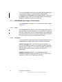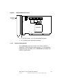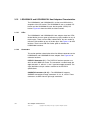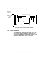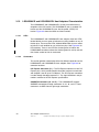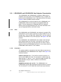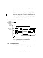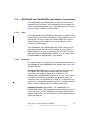
1
USER’S
GUIDE
3 Gbit/s Serial Attached SCSI
Host Adapters
LSISAS3040X
LSISAS3041X,
LSISAS3041E,
LSISAS3442X,
LSISAS3442E,
LSISAS3080X,
LSISAS3800X
LSISAS3041XL
LSISAS3041EL
LSISAS3442XL
LSISAS3442EL
LSISAS3080XL
February 2006
Version 2.0
®
DB15-000333-01
Electromagnetic Compatibility Notices
This device complies with Part 15 of the FCC Rules. Operation is subject to the following two conditions:
1.
2.
This device may not cause harmful interference, and
This device must accept any interference received, including interference that may cause undesired operation.
This equipment has been tested and found to comply with the limits for a Class B digital device, pursuant to part 15
of the FCC Rules. These limits are designed to provide reasonable protection against harmful interference in a
residential installation. This equipment generates, uses, and can radiate radio frequency energy and, if not installed
and used in accordance with the instructions, may cause harmful interference to radio communications. However,
there is no guarantee that interference will not occur in a particular installation. If this equipment does cause harmful
interference to radio or television reception, which can be determined by turning the equipment off and on, the user
is encouraged to try to correct the interference by one or more of the following measures:
•
•
•
•
Reorient or relocate the receiving antenna.
Increase the separation between the equipment and the receiver.
Connect the equipment into an outlet on a circuit different from that to which the receiver is connected.
Consult the dealer or an experienced radio/TV technician for help.
Shielded cables for SCSI connection external to the cabinet are used in the compliance testing of this Product.
LSI Logic is not responsible for any radio or television interference caused by unauthorized modification of this
equipment or the substitution or attachment of connecting cables and equipment other than those specified by
LSI Logic. The correction of interferences caused by such unauthorized modification, substitution, or attachment will
be the responsibility of the user.
The LSI Logic LSISAS PCI/PCI-X/PCI Express host adapters (LSISAS3040X, LSISAS3041X, LSISAS3041XL,
LSISAS3442X, LSISAS3442XL, LSISAS3080X, LSISAS3080XL, LSISAS3800X, LSISAS3041E, LSISAS3041EL,
LSISAS3442E, and LSISAS3442EL) are tested to comply with FCC standards for home or office use.
This Class B digital apparatus meets all requirements of the Canadian Interference-Causing Equipment Regulations.
Cet appareil numérique de la classe B respecte toutes les exigences du Règlement sur le matériel brouilleur du
Canada.
This is a Class B product based on the standard of the Voluntary Control Council for Interference from Information
Technology Equipment (VCCI). If this is used near a radio or television receiver in a domestic environment, it may
cause radio interference. Install and use the equipment according to the instruction manual.
LSI Logic Asia, Inc. Taiwan Branch
10/F, 156, Min Sheng E. Rd., Section 3,
Taipei, Taiwan, R.O.C.
Tel: 886.2.2718.7828
FAX: 886.2.2718.8869
LSI Logic Corporation
North American Headquarters
Milpitas, CA
Tel: 408.433.8000
ii
Version 2.0
Copyright © 2005, 2006 by LSI Logic Corporation. All rights reserved.
This document contains proprietary information of LSI Logic Corporation. The
information contained herein is not to be used by or disclosed to third parties
without the express written permission of an officer of LSI Logic Corporation.
LSI Logic products are not intended for use in life-support appliances, devices,
or systems. Use of any LSI Logic product in such applications without written
consent of the appropriate LSI Logic officer is prohibited.
Document DB15-000333-01, Version 2.0, February 2006
This document describes the LSI Logic Corporation LSISAS3040X,
LSISAS3041X, LSISAS3041XL, LSISAS3041E, LSISAS3041EL, LSISAS3442X,
LSISAS3442XL, LSISAS3442E, LSASAS3442EL, LSISAS3080X,
LSISAS3080XL, and LSISAS3800X, PCI/PCI-X/PCI Express to SAS/SATA host
adapters and will remain the official reference source for all revisions/releases of
these products until rescinded by an update.
LSI Logic Corporation reserves the right to make changes to any products herein
at any time without notice. LSI Logic does not assume any responsibility or
liability arising out of the application or use of any product described herein,
except as expressly agreed to in writing by LSI Logic; nor does the purchase or
use of a product from LSI Logic convey a license under any patent rights,
copyrights, trademark rights, or any other of the intellectual property rights of
LSI Logic or third parties.
Copyright © 2005, 2006 by LSI Logic Corporation. All rights reserved.
TRADEMARK ACKNOWLEDGMENT
LSI Logic, the LSI Logic logo design, Fusion-MPT and Integrated RAID are
trademarks or registered trademarks of LSI Logic Corporation. Windows and
Windows NT are registered trademarks of Microsoft Corporation. All other brand
and product names may be trademarks of their respective companies.
SR
To receive product literature, visit us at http://www.lsilogic.com.
For a current list of our distributors, sales offices, and design resource
centers, view our web page located at
http://www.lsilogic.com/contacts/index.html
iii
Version 2.0
Copyright © 2005, 2006 by LSI Logic Corporation. All rights reserved.
iv
Version 2.0
Copyright © 2005, 2006 by LSI Logic Corporation. All rights reserved.
Preface
This document is the user’s guide for the LSI Logic 3.0 Gbit/s SAS to
PCI/PCI-X/PCI Express host adapters referred to as LSISAS host
adapters. It contains a functional description of the LSISAS host adapters
as well as physical and electrical specifications. It also contains
instructions for installing the host adapters and for connecting SAS
devices.
Audience
This document assumes that you have some familiarity with Serial
Attached SCSI (SAS) devices and PCI/PCI-X/PCI Express devices. This
document benefits people installing and using the LSISAS host adapter.
Organization
This document has the following chapters:
•
Chapter 1, Introduction, describes the LSISAS host adapters.
•
Chapter 2, Hardware Installation, describes how to install the
LSISAS host adapters in a system.
•
Chapter 3, Host Adapter Characteristics, provides the
environmental and electrical specifications for the LSISAS host
adapters. This chapter also provides the mechanical drawings and
connector locations for the LSISAS host adapters.
3 Gbit/s Serial Attached SCSI Host Adapters User’s Guide
Version 2.0
Copyright © 2005, 2006 by LSI Logic Corporation. All rights reserved.
v
Related Publications
LSI Logic Documents
LSISAS1064 PCI-X to 4-Port Serial Attached SCSI/SATA Controller
Technical Manual, Document No. DB14-000274-xx
LSISAS1064E PCI Express to 4-Port Serial Attached SCSI Controller
Technical Manual, Document No. DB14-000331-xx
LSISAS1068 PCI-X to 8-Port Serial Attached SCSI/SATA Controller
Technical Manual, Document No. DB14-000287-xx
LSISAS1068E PCI Express to 8-Port Serial Attached SCSI Controller
Technical Manual, Document No. DB14-000330-xx
Fusion-MPT™ Device Management User’s Guide, Document No.
DB15-000186-xx
Integrated RAID User’s Guide, Document No. DB15-000292-xx
LSI Logic World Wide Web Home Page
www.lsilogic.com
ANSI
11 West 42nd Street
New York, NY 10036
(212) 642-4900
InterNational Committee on Information Technology Standards
(INCITIS) T10 Technical Committee
http://www.t10.org
Global Engineering Documents
15 Inverness Way East
Englewood, CO 80112
(800) 854-7179 or (303) 397-7956 (outside U.S.); FAX (303) 397-2740
vi
Preface
Version 2.0
Copyright © 2005, 2006 by LSI Logic Corporation. All rights reserved.
PCI Special Interest Group
2575 N. E. Katherine
Hillsboro, OR 97214
(800) 433-5177; (503) 693-6232 (International); FAX (503) 693-8344
Revision Record
Version
Date
Remarks
1.0
2/2005
Initial release provides information about the LSISAS3040X, LSISAS3041X,
LSISAS3041XL, LSISAS3442X, LSISAS3442XL, LSISAS3080X,
LSISAS3080XL, and LSISAS3800X PCI/PCI-X to SAS/SATA host adapters.
2.0
1/2006
Changed the title of this user guide from LSISAS (Serial Attached SCSI)
PCI/PCI-X Host Adapters User’s Guide to 3 Gbit/s Serial Attached SCSI Host
Adapters User’s Guide.
Added the LSISAS3041E/LSISAS3041EL and LSISAS3442E/LSIASA3442EL
PCI Express host adapters.
Preface
Version 2.0
vii
Copyright © 2005, 2006 by LSI Logic Corporation. All rights reserved.
viii
Preface
Version 2.0
Copyright © 2005, 2006 by LSI Logic Corporation. All rights reserved.
Contents
Chapter 1
Introduction
1.1
1.2
1.3
1.4
Overview
Features
PCI Performance
1.3.1
PCI/PCI-X Features
1.3.2
PCI Express Features
Software
1-1
1-3
1-4
1-4
1-5
1-6
Chapter 2
Hardware Installation
2.1
2.2
Quick Installation Instructions
Detailed Installation Instructions
2-1
2-2
Chapter 3
Host Adapter Characteristics
3.1
Characteristics of the LSISAS Host Adapters
3-1
3.1.1
LSISAS3040X Host Adapter Characteristics
3-2
3.1.2
LSISAS3041X and LSISAS3041XL Host Adapters
Characteristics
3-4
3.1.3
LSISAS3041E and LSISAS3041EL Host Adapters
Characteristics
3-6
3.1.4
LSISAS3442X and LSISAS3442XL Host Adapters
Characteristics
3-8
3.1.5
LSISAS3442E and LSISAS3442EL Host Adapters
Characteristics
3-11
3.1.6
LSISAS3080X and LSISAS3080XL Host Adapters
Characteristics
3-13
3.1.7
LSISAS3800X Host Adapter Characteristics
3-15
3 Gbit/s Serial Attached SCSI Host Adapters User’s Guide
Version 2.0
Copyright © 2005, 2006 by LSI Logic Corporation. All rights reserved.
ix
3.2
Electrical and Environmental Specifications
3.2.1
Electrical Characteristics
3.2.2
Thermal and Atmospheric Characteristics
3.2.3
Safety Characteristics
Customer Feedback
x
Contents
Version 2.0
Copyright © 2005, 2006 by LSI Logic Corporation. All rights reserved.
3-17
3-17
3-17
3-18
Figures
2.1
2.2
3.1
3.2
3.3
3.4
3.5
3.6
3.7
Installing an LSISAS x4 Host Adapter in a PCI-X Slot
2-3
Installing an LSISAS x8 Host Adapter in a PCI Express Slot 2-4
LSISAS3040X Board Layout
3-3
LSISAS3041X and LSISAS3041XL Board Layout
3-5
LSISAS3041E and LSISAS3041EL Board Layout
3-7
LSISAS3442X and LSISAS3442XL Board Layout
3-9
LSISAS3442E and LSISAS3442EL Board Layout
3-12
LSISAS3080X and LSISAS3080XL Board Layout
3-14
LSISAS3800X Board Layout
3-16
Contents
Version 2.0
xi
Copyright © 2005, 2006 by LSI Logic Corporation. All rights reserved.
xii
Contents
Version 2.0
Copyright © 2005, 2006 by LSI Logic Corporation. All rights reserved.
Tables
1.1
1.2
1.3
3.1
LSISAS Host Adapters and Controllers
SAS Bandwidths
Software Support
Maximum Power Requirements
Contents
Version 2.0
1-2
1-3
1-7
3-17
xiii
Copyright © 2005, 2006 by LSI Logic Corporation. All rights reserved.
xiv
Contents
Version 2.0
Copyright © 2005, 2006 by LSI Logic Corporation. All rights reserved.
Chapter 1
Introduction
This chapter describes the LSI Logic Serial Attached SCSI (LSISAS)
PCI/PCI-X/PCI Express host adapters and consists of the following
sections:
1.1
•
Section 1.1, “Overview”
•
Section 1.2, “Features”
•
Section 1.3, “PCI Performance”
•
Section 1.4, “Software”
Overview
The LSISAS PCI/PCI-X/PCI Express host adapters provide four or eight
serial ports for connection to SAS/SATA (Serial ATA) devices. Each port
is capable of 3.0 Gbits/s SAS link rates and 3.0 Gbits/s SATA link rates.
The PCI-X interface operates as a zero wait state bus master with data
bursts up to 1064 Mbytes/s on a 64-bit PCI-X 133 MHz bus. The PCI
Express transmission and reception data rate is 2.5 Gbits/s in each
direction, yielding a total bandwidth of 5.0 Gbits/s for each full-duplex
lane. The LSISAS PCI Express host adapters are implemented using
four or eight PCI Express phys, which provide possible host-side
maximum transmission and reception rates of up to 4.0 Gbytes/s.
The LSISAS host adapters contain Flash ROM for storing the BIOS and
firmware, and NVSRAM for storing nonvolatile RAID information. The
LSISAS3442E, LSISAS3442EL, LSISAS3442X, and LSISAS3800X host
adapters provide a 128 K x 36-bit PBSRAM memory device for storing
SAS Address Port information allowing for connection to more than 128
devices. The LEDs on the host adapters report a heartbeat, activity, and
fault conditions when detected by firmware. Fusion-MPT™ firmware
operates the host adapter.
3 Gbit/s Serial Attached SCSI Host Adapters User’s Guide
Version 2.0
Copyright © 2005, 2006 by LSI Logic Corporation. All rights reserved.
1-1
The LSISAS PCI/PCI-X interface is compliant with the PCI-X
Specification, revision 2.0. The LSISAS PCI Express interface is
compliant with the PCI Express Specification, revision 1.0a. All PCI
software is backwards compliant with previous versions of the PCI/PCIX specifications. The PCI/PCI-X host adapters are keyed for 3.3 V
PCI/PCI-X add-in card slots. The PCI Express host adapters are not
keyed for a specific signaling level voltage. The LSISAS implements the
PCI Express interface as a x4 or x8 interface. The LSISAS host adapters
use either a standard PCI or a low-profile PCI bracket type. The LSISAS
host adapter SAS interface is compatible with the ANSI Serial Attached
SCSI Specification, revision 1.0 and the Serial ATA Specification, revision
1.0a.
The functionality of LSISAS host adapters come from either the
LSISAS1064/LSISAS1064E controller chips or the LSISAS1068/
LSISAS1068E controller chips. The LSISAS1064/LSISAS1064E
integrates four high-performance SAS/SATA phys and the
LSISAS1068/LSISAS1068E integrates eight high-performance
SAS/SATA phys. The design of LSISAS host adapters makes it easy to
add SAS interfaces to any computer, workstation, or server with a
PCI/PCI-X/PCI Express bus.
Table 1.1 shows the LSISAS controllers and their associated host
adapters that support SAS/SATA devices. Boards without an “L” after the
numbers in their name use a standard PCI bracket type. Boards with an
“L” after the numbers in their name use a low-profile PCI bracket type.
Boards with an “X” after the numbers in their name use the PCI-X bus
and boards with an “E” after the numbers in their name use the PCI
Express bus.
Table 1.1
1-2
LSISAS Host Adapters and Controllers
Controllers
LSISAS Host Adapters
PCI Slot
LSISAS1064
LSISAS3040X, LSISAS3041X, LSISAS3041XL PCI/PCI-X
LSISAS1068
LSISAS3442X, LSISAS3442XL,
PCI/PCI-X
LSISAS3080X, LSISAS3080XL, LSISAS3800X
LSISAS1064E
LSISAS3041E LSISAS3041EL
PCI Express
LSISAS1068E
LSISAS3442E, LSISAS3442EL
PCI Express
Introduction
Version 2.0
Copyright © 2005, 2006 by LSI Logic Corporation. All rights reserved.
1.2
Features
This section lists features of the LSISAS host adapters:
•
Table 1.2
Supports narrow port and wide port as shown in Table 1.2.
SAS Bandwidths
Half Duplex
Full Duplex
Narrow Port (1 Lane)—300 Mbytes/s
Narrow Port (1 Lane)—600 Mbytes/s
Wide Port (2 Lanes)—600 Mbytes/s
Wide Port (2 Lanes)—1200 Mbytes/s
Wide Port (4 Lanes)—1200 Mbytes/s
Wide Port (4 Lanes)—2400 Mbytes/s
•
Supports SSP, STP, and SMP as defined in the Serial Attached SCSI
(SAS) Specification, version 1.0.
•
Supports SATA as defined in the Serial ATA Specification, version
1.0a.
•
Provides configurable drive spin-up sequencing on a per-phy basis.
•
Simplifies cabling with a point-to-point, serial architecture.
•
Provides smaller and thinner cables that do not restrict airflow.
•
Provides a serial, point-to-point, enterprise-level storage interface.
•
Transfers data using SCSI information units.
•
Provides two LEDs for each phy to indicate link activity and faults for
the LSISAS3040X, LSISAS3041X, LSISAS3041XL, LSISAS3442X,
LSISAS3442XL, LSISAS3800X, LSISAS3041E, and LSISAS3041EL
host board adapters (HBAs).
•
Provides two light pipes routed through the PCI bracket for the
LSISAS3442X, LSISAS3442XL, LSISAS3080X, LSISAS3080XL,
LSISAS3800X, LSISAS3442E, and LSISAS3442EL host adapters.
One light pipe indicates activity on any phy. The other light pipe
indicates a heartbeat or a fault condition.
•
Provides compatibility with SATA target devices.
Features
Version 2.0
1-3
Copyright © 2005, 2006 by LSI Logic Corporation. All rights reserved.
1.3
PCI Performance
LSISAS host adapter boards support both PCI/PCI-X and PCI Express
interfaces. The following lists are of their features.
1.3.1
PCI/PCI-X Features
PCI/PCI-X features of the LSISAS host adapters include:
•
1-4
PCI/PCI-X Supports a 133 MHz, 64-bit PCI/PCI-X interface that does
the following:
–
Operates up to 133 MHz PCI-X
–
Operates at 33 MHz or 66 MHz PCI
–
Supports 32-bit or 64-bit data transfers
–
Supports 32-bit or 64-bit addressing through Dual Address
Cycles (DAC)
–
Provides a theoretical 1064 Mbytes/s PCI bandwidth
–
Complies with the PCI Local Bus Specification, revision 3.0
–
Complies with the PCI-X Addendum to the PCI Local Bus
Specification, revision 2.0
–
Complies with the PCI Bus Power Management Interface
Specification, revision 1.2
–
Complies with the PC2001 Specification
•
Provides unequalled performance through the Fusion-MPT
architecture
•
Provides high throughput and low CPU utilization to offload the host
processor
•
Presents a single electrical load to the PCI Bus
•
Reduces Interrupt Service Routine (ISR) overhead with interrupt
coalescing
•
Supports 32-bit or 64-bit data bursts with variable burst lengths
•
Supports the PCI Cache Line Size register
•
Supports the PCI Memory Write and Invalidate, Memory Read Line,
and Memory Read Multiple commands
Introduction
Version 2.0
Copyright © 2005, 2006 by LSI Logic Corporation. All rights reserved.
1.3.2
•
Supports the PCI-X Memory Read Dword, Split Completion, Memory
Read Block, and Memory Write Block commands
•
Supports 16 PCI-X Split Transaction cycles
•
Supports backwards compatibility with previous revisions of the PCI
specification
•
Provides a full 32-bit or 64-bit PCI-X DMA bus master
•
Reduces time-to-market with the Fusion-MPT architecture that
provides:
–
Single driver binary for SAS/SATA, SCSI, and Fibre Channel
products
–
One firmware build that supports all Integrated RAID™
capabilities
–
Thin and easy to develop drivers
–
Reduced integration and certification effort
PCI Express Features
The PCI Express features of the LSISAS host adapters include:
•
Provides four or eight PCI Express phys
•
Supports a single-phy (1 lane) link transfer rate up to 2.5 Gbits/s in
each direction
•
Supports x8, x4, and x1 link widths
•
Automatically downshifts to a x4 link width if plugged into a x4
connector or into a x8 connector that is wired as a x4 connector
•
Provides a scalable interface
•
–
Single-lane aggregate bandwidth of up to 0.5 Gbytes/s
(500 MBytes/s)
–
Quad-lane aggregate bandwidth of up to 2.0 Gbytes/s
(2000 Mbytes/s)
–
8-lane aggregate bandwidth of up to 4.0 Gbytes/s
(4000 Mbytes/s)
Supports serial, point-to-point interconnections between devices
–
Reduces the electrical load of the connection
PCI Performance
Version 2.0
1-5
Copyright © 2005, 2006 by LSI Logic Corporation. All rights reserved.
–
1.4
Enables higher transmission and reception frequencies
•
Supports lane reversal and polarity inversion
•
Supports PCI Express Hot Plug
•
Supports Power Management
–
Supports PCI Power Management 1.2
–
Supports Active State Power Management (ASPM), including the
L0, L0s, L1 states, by placing links in a power-savings mode
during times of no link activity
•
Contains a replay buffer that preserves a copy of the data for
retransmission in case a CRC error occurs
•
Supports the PCI Express Advanced Error Reporting capabilities
•
Uses a packetized and layered architecture
•
Achieves a high bandwidth per pin with low overhead and low latency
•
PCI Express is software compatible with PCI and PCI-X software
–
Leverages existing PCI device drivers
–
Supports the Memory, I/O, and Configuration address spaces
–
Supports memory read/write transactions, I/O read/write
transactions, and configuration read/write transactions
•
Provides 4 Kbytes of PCI Configuration address space per device.
•
Supports posted and non-posted transactions
•
Provides quality of service (QOS) link configuration and arbitration
policies
•
Supports Traffic Class 0 and one virtual channel
•
Supports Message Signaled Interrupts (both MSI and MSI-X) as well
as INTx interrupt signaling for legacy PCI support
•
Supports end-to-end CRC (ECRC) and Advanced Error Reporting
Software
The LSISAS host adapters support all major operating systems, as
shown in Table 1.3.
1-6
Introduction
Version 2.0
Copyright © 2005, 2006 by LSI Logic Corporation. All rights reserved.
Table 1.3
Software Support
OS Support
Versions
Windows
XP, 2000, Server 2003 32-bit and 64-bit
(x86, AMD, and IA-64)
Linux: Red Hat Enterprise Linux (RHEL) 3 and 4
Linux: SuSE Enterprise Server
(SLES) 8 and 9
Novel NetWare
5.1 and 6.5
Sun Sparc Solaris
2.6, 2.7, 2.8, 2.9, and 2.10
Utilities
Install, Flash and BIOS Configuration Utility
The LSISAS host adapters use the Fusion-MPT architecture for all major
operating systems, which allows for thinner drivers for better
performance. To obtain a device driver that supports your operating
system, contact the LSI Logic Technical Support team at 719-533-7230
or visit our web site at http://www.lsilogic.com.
Software
Version 2.0
1-7
Copyright © 2005, 2006 by LSI Logic Corporation. All rights reserved.
1-8
Introduction
Version 2.0
Copyright © 2005, 2006 by LSI Logic Corporation. All rights reserved.
Chapter 2
Hardware Installation
This chapter provides both quick instructions and detailed instructions on
how to install the LSISAS host adapter. This chapter consists of the
following sections:
2.1
•
Section 2.1, “Quick Installation Instructions”
•
Section 2.2, “Detailed Installation Instructions”
Quick Installation Instructions
The following steps summarizes the installation instructions.
Use these instructions to install your LSISAS host adapter if you are
comfortable with the installation procedure. Section 2.2 provides detailed
installation instructions.
Step 1.
Unpack the host adapter and inspect it for damage.
Step 2.
Turn off the system and remove the power cord(s).
Step 3.
Remove the cover from the system.
Step 4.
Insert the host adapter in an available PCI/PCI-X or PCI
Express slot.
Step 5.
Secure the bracket to the system’s chassis.
Step 6.
Connect the serial cable(s) between the host adapter and the
serial hard disk drive(s). Figure 2.1 and Figure 2.2 illustrate the
locations of the connectors on your host adapter.
Step 7.
Replace the cover and the power cord(s), then power-up the
system.
LSISAS host adapter hardware installation is complete.
3 Gbit/s Serial Attached SCSI Host Adapters User’s Guide
Version 2.0
Copyright © 2005, 2006 by LSI Logic Corporation. All rights reserved.
2-1
2.2
Detailed Installation Instructions
The following steps provide detailed installation instructions:
Step 1.
Unpack the host adapter and inspect it for damage.
Unpack the host adapter in a static-free environment. Remove
the host adapter from the anti-static bag and inspect it for
damage. Contact LSI Logic or your OEM support representative
if the host adapter appears damaged.
Step 2.
Turn off the system and disconnect the power cord(s).
Turn off the system’s power and physically remove the power
cord(s) from the system.
Step 3.
Remove the cover from the system.
Remove the cover from the system’s chassis. Disconnect the
system from any networks.
Step 4.
Insert the host adapter in an available PCI/PCI-X or PCI
Express slot.
Locate an empty PCI/PCI-X or PCI Express slot. Remove the
blank bracket panel on the back of the computer that is aligned
with the PCI/PCI-X or PCI Express slot you have selected.
Save the bracket screw when present.
Align the host adapter to a PCI/PCI-X or PCI Express slot.
Press down gently but firmly to properly seat the host adapter
in the slot. Figure 2.1 and Figure 2.2 illustrate how to insert the
host adapter in a PCI/PCI-X or PCI Express slot.
Note:
Step 5.
The PCI/PCI-X HBAs only are keyed for a 3.3 V slot. The
keying of edge connector J1 prevents the card from being
installed in a 5 V slot.
Secure the bracket to the system’s chassis.
Install the bracket screw, when present, or engage the system’s
retention mechanism to secure the host adapter to the system’s
chassis.
Step 6.
2-2
Connect the serial cable(s) between the host adapter and the
serial hard disk drive(s) (HDD). Figure 2.1 and Figure 2.2
illustrate the locations of the connectors on your host adapter.
Hardware Installation
Version 2.0
Copyright © 2005, 2006 by LSI Logic Corporation. All rights reserved.
Step 7.
Replace the cover and the power cord(s), then power-up the
system.
Replace the system’s cover, reconnect the power cord(s) and
any network cables. Turn power on to the system.
LSISAS host adapter hardware installation is complete.
Figure 2.1
Installing an LSISAS x4 Host Adapter in a PCI-X Slot
Serial Signal
Cable
Bracket
Screw
HDD
Connector
Press Here
HBA Single
Lane Connector
Press Here
32-bit Slots
(3.3 V)
Edge of
Host Board
Note:
64-bit Slots
(3.3 V)
The HBA shape, size, and locations of components on your
x4 HBA and its bracket may vary from this illustration.
Detailed Installation Instructions
Version 2.0
Copyright © 2005, 2006 by LSI Logic Corporation. All rights reserved.
2-3
Figure 2.2
Installing an LSISAS x8 Host Adapter in a PCI Express
Slot
HDD
Connector
Bracket
Screw
Serial Signal
Cables
Press Here
HBA to HDD
Breakout Cable
Press Here
4 Lane Internal
HBA Connector
SFF-8484
4 Lane
External
PCB
Receptacle
and Cable
with
Jackscrews
SFF-8470
Edge of
Host Board
Note:
2-4
32-bit Slots
(3.3 V)
PCI Express x8 Slot
64-bit Slots
(3.3 V)
The HBA shape, size, and locations of components on
your x8 HBA and its bracket may vary from this illustration.
A PCI Express connector is smaller than a PCI/PCI-X
connector.
Hardware Installation
Version 2.0
Copyright © 2005, 2006 by LSI Logic Corporation. All rights reserved.
Chapter 3
Host Adapter Characteristics
This chapter describes the characteristics of the LSISAS PCI/PCI-X and
PCI Express host adapters. The chapter includes these topics:
3.1
•
Section 3.1, “Characteristics of the LSISAS Host Adapters”
•
Section 3.2, “Electrical and Environmental Specifications”
Characteristics of the LSISAS Host Adapters
The LSISAS host adapters use either the LSISAS1064/1064E controller
or the LSISAS1068/1068E controller. The LSISAS1064/1064E controller
connects up to four SAS/SATA devices to a computer system through the
PCI/PCI-X/PCI Express interface. The LSISAS1068/1068E controller
connects up to eight SAS/SATA devices to a computer system through
the PCI/PCI-X/PCI Express interface. The LSISAS1064 and the
LSISAS1068 support a 133 MHz, 64-bit PCI-X bus. The LSISAS1064E
and LSISAS1068E are implemented using four or eight PCI Express
phys. Each phy operates at 2.5 Gbits/s which provide possible host-side
maximum transmission and reception rates of up to 4.0 Gbytes/s.
The LSISAS1064/1064E and the LSISAS1068/1068E controller chips
contain the PCI/PCI-X or PCI Express functionality for the LSISAS host
adapters. The controller chip connects directly to the PCI/PCI-X or PCI
Express bus and generates timing and protocol in compliance with the
PCI, PCI-X, and PCI Express specifications.
The LSISAS1064/1064E and the LSISAS1068/1068E controller chips
contain the SAS/SATA functionality for the LSISAS host adapters. The
controller chips connect channels directly to the SAS/SATA devices.
The LSISAS host adapters provide up to 4 M x 8-bit Flash ROM for
storing the BIOS and firmware. The LSISAS host adapters provide up to
3 Gbit/s Serial Attached SCSI Host Adapters User’s Guide
Version 2.0
Copyright © 2005, 2006 by LSI Logic Corporation. All rights reserved.
3-1
32 K x 8-bit NVSRAM for storing the nonvolatile RAID information when
a system failure happens. The LSISAS3442E, LSISAS3442EL,
LSISAS3442X, and LSISAS3800X host adapters provide a 128 K x 36bit PBSRAM memory device for storing SAS Address Port information
allowing for connection to more than 128 devices.
3.1.1
LSISAS3040X Host Adapter Characteristics
The LSISAS3040X host adapter uses a standard PCI bracket as shown
in Figure 3.1.
3.1.1.1
LEDs
The LSISAS3040X host adapter has four LEDs, labeled A0-A3, that turn
green to indicate an activity condition on any of the four phys. There are
four LEDs, labeled F0-F3, that turn amber to indicate a fault condition on
any of the four phys. See Figure 3.1 for LED locations. There is one LED
that flashes green to indicate the LSISAS1064 heartbeat.
3.1.1.2
Connectors
This section provides a description of the five different connectors on the
LSISAS3040X host adapter. See Figure 3.1 for connector locations.
PCI/PCI-X Connector (J1) – The PCI/PCI-X interface operates as a
32-bit or 64-bit DMA bus master. The connection is made through the
edge connector J1, which is a +3.3 V type board edge connector. The
signal definitions and pin numbers conform to the PCI/PCI-X
specifications.
SAS/SATA Connectors (J2–J5) – The LSISAS3040X supports
SAS/SATA connections through connectors J2, J3, J4, and J5. These
connectors are SATA internal right-angle connectors.
3-2
Host Adapter Characteristics
Version 2.0
Copyright © 2005, 2006 by LSI Logic Corporation. All rights reserved.
LSISAS3040X Board Layout
Fault LEDs
LSISAS3040X
Standard PCI
Bracket
Activity LEDs
Heart beat
Figure 3.1
Port 3
J2
Port 2
Port 1
Port 0
J4
J3
J5
LSISAS1064
J1
3.1.1.3
•
J1: PCI/PCI-X 64-bit, +3.3 V type board edge connector
•
J2–J5: SATA internal right-angle connectors
Physical Characteristics
The LSISAS3040X board is 6.6 inches x 3.4 inches. PCI/PCI-X
connection is made through the edge connector J1. The component
height on the top and bottom of the LSISAS3040X board follows the
PCI/PCI-X specifications.
Characteristics of the LSISAS Host Adapters
Version 2.0
Copyright © 2005, 2006 by LSI Logic Corporation. All rights reserved.
3-3
3.1.2
LSISAS3041X and LSISAS3041XL Host Adapters Characteristics
The LSISAS3041X and LSISAS3041XL are the same HBA with the
exception of the PCI bracket. The LSISAS3041X uses a standard PCI
bracket and the LSISAS3041XL uses the low-profile (LPPCI) PCI
bracket. Figure 3.2 shows the HBAs and their brackets.
3.1.2.1
LEDs
The LSISAS3041X and LSISAS3041XL host adapters have four LEDs,
labeled A0-A3, that turn green to indicate an activity condition on any of
the four phys. There are four LEDs, labeled F0-F3, that turn amber to
indicate a fault condition on any of the four phys. See Figure 3.2 for LED
locations. There is one LED that flashes green to indicate the
LSISAS1064 heartbeat.
3.1.2.2
Connectors
This section provides a description of the five different connectors on the
LSISAS3041X and LSISAS3041XL host adapters. See Figure 3.2 for
connector locations.
PCI/PCI-X Connector (J1) – The PCI/PCI-X interface operates as a
32-bit or 64-bit DMA bus master. The connection is made through the
edge connector J1, which is a +3.3 V type board edge connector. The
signal definitions and pin numbers conform to the PCI/PCI-X
specifications.
SAS/SATA Connectors (J2–J5) – The LSISAS3041X supports
SAS/SATA connections through connectors J2, J3, J4, and J5. These
connectors are SATA internal right-angle connectors.
3-4
Host Adapter Characteristics
Version 2.0
Copyright © 2005, 2006 by LSI Logic Corporation. All rights reserved.
Figure 3.2
LSISAS3041X and LSISAS3041XL Board Layout
LSISAS3041X
Standard PCI
Bracket
Port 2
J2
J3
Fault
Activity
Heart beat
Port 3
LSISAS3041XL
Low-Profile
(LPPCI)
PCI Bracket
Port 1
Port 0
J4
J5
LSISAS1064
J1
3.1.2.3
•
J1: PCI/PCI-X 64-bit, +3.3 V type board edge connector
•
J2–J5: SATA internal right-angle connectors
Physical Characteristics
The LSISAS3041X and LSISAS3041XL boards are 6.6 inches x 2.536
inches. PCI/PCI-X connection is made through the edge connector J1.
The component height on the top and bottom of the LSISAS3041X and
LSISAS3041XL boards follows the PCI/PCI-X specifications.
Characteristics of the LSISAS Host Adapters
Version 2.0
Copyright © 2005, 2006 by LSI Logic Corporation. All rights reserved.
3-5
3.1.3
LSISAS3041E and LSISAS3041EL Host Adapters Characteristics
The LSISAS3041E and LSISAS3041EL are the same HBA with the
exception of the PCI bracket. The LSISAS3041E uses a standard PCI
bracket and the LSISAS3041EL uses the low-profile (LPPCI) PCI
bracket. Figure 3.3 shows the HBAs and their brackets.
3.1.3.1
LEDs
The LSISAS3041E and LSISAS3041EL host adapters have four LEDs,
labeled A0-A3, that turn green to indicate an activity condition on any of
the four phys. There are four LEDs, labeled LNP0-LNP3, that turn amber
to indicate a fault condition on any of the four phys. See Figure 3.3 for
LED locations. There is one LED that flashes green to indicate the
LSISAS1064E heartbeat and one that flashes green for activity and one
that flashes amber for fault in the bracket.
3.1.3.2
Connectors
This section provides a description of the five different connectors on the
LSISAS3041E and LSISAS3041EL host adapters. See Figure 3.3 for
connector locations.
PCI Express Connector (J1) – The PCI Express interface has four PCI
Express phys, which provide possible host-side maximum transmission
and reception rates of up to 2.0 Gbytes/s. The PCI Express connection
is made through the edge connector J1. The signal definitions and pin
numbers conform to the PCI Express specifications.
SAS/SATA Connectors (J2, J5–J7) – The LSISAS3041E supports
SAS/SATA connections through connectors J2, J5, J6, and J7. These
connectors are SATA internal right-angle connectors.
3-6
Host Adapter Characteristics
Version 2.0
Copyright © 2005, 2006 by LSI Logic Corporation. All rights reserved.
Figure 3.3
LSISAS3041E and LSISAS3041EL Board Layout
LSISAS3041E
Standard PCI Bracket
LSISAS3041EL
Low-Profile
(LPPCI)
PCI Bracket
Port 3
Port 2
Port 1
Port 0
J3
U5
J4
J2
LSISAS1064E
J5
J6
J7
Fault LEDs
J8
Activity LEDs
Two Light Pipes,
One Green and
One Bi-color
3.1.3.3
J1
•
J1: PCI Express x4 type board edge connector
•
J2, J5–J7: SATA internal right-angle connectors
Physical Characteristics
The LSISAS3041E and LSISAS3041EL boards are 6.6 inches x 2.713
inches. PCI Express x4 connection is made through the edge connector
J1. The component height on the top and bottom of the LSISAS3041E
and LSISAS3041EL boards follows the PCI Express specifications.
Characteristics of the LSISAS Host Adapters
Version 2.0
Copyright © 2005, 2006 by LSI Logic Corporation. All rights reserved.
3-7
3.1.4
LSISAS3442X and LSISAS3442XL Host Adapters Characteristics
The LSISAS3442X and LSISAS3442XL are identical HBAs with the
exception of the PCI bracket. The LSISAS3442X uses a standard PCI
bracket and the LSISAS3442XL uses a low-profile (LPPCI) PCI bracket.
Figure 3.4 shows the HBAs and their brackets.
The LSISAS3442X-R is physically identical to the LSISAS3442X and
LSISAS3442XL HBAs but also supports the Integrated RAID (IR)
options. The two components or Integrated RAID are: Integrated
Mirroring (IM) and Integrated Striping (IS). For more information on IR
see the Integrated RAID for SAS User’s Guide.
3.1.4.1
LEDs
The LSISAS3442X and LSISAS3442XL host adapters have eight LEDs,
labeled A0-A7, that turn green to indicate an activity condition on any of
the eight phys. There are eight LEDs, labeled F0-F7, that turn amber to
indicate a fault condition on any of the eight phys. See Figure 3.4 for LED
locations.
The LSISAS3442X and LSISAS3442XL host adapters have two light
pipes routed through the PCI bracket. One light pipe turns green to
indicate activity on any phy. The other light pipe is bi-color. It flashes
green to indicate the LSISAS1068 heartbeat, or it turns amber when the
LSISAS1068 firmware detects a fault condition.
3.1.4.2
Connectors
This section provides a description of the three different connectors on
the LSISAS3442X and LSISAS3442XL host adapters. See Figure 3.4 for
connector locations.
PCI/PCI-X Connector (J1) – The PCI/PCI-X interface operates as a
32-bit or 64-bit DMA bus master. The connection is made through the
edge connector J1, which is a +3.3 V type board edge connector. The
signal definitions and pin numbers conform to the PCI/PCI-X
specifications.
SAS/SATA Connectors (J2 and J5) – The LSISAS3442X and
LSISAS3442XL support SAS connections through connectors J2 and J5.
The J5 connector is an SFF-8484 SAS internal right-angle connector
3-8
Host Adapter Characteristics
Version 2.0
Copyright © 2005, 2006 by LSI Logic Corporation. All rights reserved.
with four sideband lines. The J2 connector is an SFF-8470 SAS external
right-angle connector.
J5 contains four Serial General Purpose Input Output (SGPIO) signals.
SGPIO is a method to serialize general-purpose IO signals. SGPIO
defines the communication between an initiator (for example, a host bus
adapter) and a SGPIO target (for example, a backplane holding disk
drives). The SGPIO target typically converts the output signals into
multiple parallel LED signals and provides the input signals from generalpurpose inputs. The SGPIO signals are SCLOCK on pin 14, SLOAD on
pin 15, SDATAOUT on pin 18, and SDATAIN on pin 19.
Figure 3.4
LSISAS3442X and LSISAS3442XL Board Layout
LSISAS3442X
Standard PCI Bracket
LSISAS3442XL
Low-Profile
(LPPCI)
PCI Bracket
Fault
LEDs
Two Light Pipes,
One Green and
One Bi-color
Active
LEDs
J5
LSISAS1068
J2
J1
3.1.4.3
•
J1: PCI/PCI-X 64-bit, +3.3 V type board edge connector
•
J2: SFF-8470 SAS external right-angle connector
•
J5: SFF-8484 SAS internal right-angle connector with four sideband
lines
Physical Characteristics
The LSISAS3442X and LSISAS3442XL boards are 6.6 inches x 2.536
inches. PCI/PCI-X connection is made through the edge connector J1.
Characteristics of the LSISAS Host Adapters
Version 2.0
Copyright © 2005, 2006 by LSI Logic Corporation. All rights reserved.
3-9
The component height on the top and bottom of the LSISAS3442X and
LSISAS3442XL boards follows the PCI/PCI-X specifications.
3-10
Host Adapter Characteristics
Version 2.0
Copyright © 2005, 2006 by LSI Logic Corporation. All rights reserved.
3.1.5
LSISAS3442E and LSISAS3442EL Host Adapters Characteristics
The LSISAS3442E and LSISAS3442EL are the same HBA with the
exception of the PCI bracket. The LSISAS3442E uses a standard PCI
bracket and the LSISAS3442EL uses a low-profile (LPPCI) PCI bracket.
Figure 3.5 shows the HBAs and their brackets.
3.1.5.1
LEDs
The LSISAS3442E and LSISAS3442EL host adapters have eight LEDs,
labeled A0-A7, that turn green to indicate an activity condition on any of
the eight phys. There are eight LEDs, labeled LNP0-LNP7, that turn
amber to indicate a fault condition on any of the eight phys. See
Figure 3.5 for LED locations.
The LSISAS3442E and LSISAS3442EL host adapters have two light
pipes routed through the PCI bracket. One light pipe turns green to
indicate activity on any phy. The other light pipe is bi-color. It flashes
green to indicate the LSISAS1068E heartbeat, or it turns amber when
the LSISAS1068E firmware detects a fault condition.
3.1.5.2
Connectors
This section provides a description of the three different connectors on
the LSISAS3442E and LSISAS3442EL host adapters. See Figure 3.5 for
connector locations.
PCI Express Connector (J1) – The PCI Express interface has eight
PCI Express phys, which provide possible host-side maximum
transmission and reception rates of up to 4.0 Gbytes/s. The
LSISAS3442E or LSISAS3442EL supports x8, x4, and x1 PCI Express
link widths, and automatically downshifts if plugged into either a x4
connector or into a x8 connector that is wired as a x4 connector. The
connection is made through the edge connector J1. The signal definitions
and pin numbers conform to the PCI Express specifications.
SAS/SATA Connectors (J2 and J5) – The LSISAS3442E and
LSISAS3442EL support SAS connections through connectors J2 and J5.
The J5 connector is an SFF-8484 SAS internal right-angle connector
with four sideband lines. The J2 connector is an SFF-8470 SAS external
right-angle connector.
Characteristics of the LSISAS Host Adapters
Version 2.0
Copyright © 2005, 2006 by LSI Logic Corporation. All rights reserved.
3-11
J5 contains four Serial General Purpose Input Output (SGPIO) signals.
SGPIO is a method to serialize general-purpose IO signals. SGPIO
defines the communication between an initiator (for example, a host bus
adapter) and a SGPIO target (for example, a backplane holding disk
drives). The SGPIO target typically converts the output signals into
multiple parallel LED signals and provides the input signals from generalpurpose inputs. The SGPIO signals are SCLOCK on pin 14, SLOAD on
pin 15, SDATAOUT on pin 18, and SDATAIN on pin 19.
Figure 3.5
LSISAS3442E and LSISAS3442EL Board Layout
LSISAS3442X
Standard PCI Bracket
LSISAS3442XL
Low-Profile
(LPPCI)
PCI Bracket
J6
U5
Two Light Pipes,
One Green and
One Bi-color
LSISAS1068E
Fault
LEDs
J5
Active
LEDs
J2
J1
3.1.5.3
•
J1: PCI Express x8, +3.3 V type board edge connector
•
J2: SFF-8470 SAS external right-angle connector
•
J5: SFF-8484 SAS internal right-angle connector with four sideband
lines
•
J6: 4-pin, right angle, 0.1” pitch, pin header for driving external
activity LED.
Physical Characteristics
The LSISAS3442E and LSISAS3442EL boards are 6.6 inches x 2.713
inches. PCI Express x8 connection is made through the edge connector
J1. The component height on the top and bottom of the LSISAS3442E
and LSISAS3442EL boards follows the PCI Express specifications.
3-12
Host Adapter Characteristics
Version 2.0
Copyright © 2005, 2006 by LSI Logic Corporation. All rights reserved.
3.1.6
LSISAS3080X and LSISAS3080XL Host Adapters Characteristics
The LSISAS3080X and LSISAS3080XL are the same HBA with the
exception of the PCI bracket. The LSISAS3080X uses a standard PCI
bracket and the LSISAS3080XL uses a low-profile (LPPCI) PCI bracket.
Figure 3.6 shows the HBAs and their brackets.
3.1.6.1
LEDs
The LSISAS3080X and LSISAS3080XL host adapters have two light
pipes routed through the PCI bracket. One light pipe turns green to
indicate activity on any phy. The other light pipe is bi-color. It flashes
green to indicate the LSISAS1068 heartbeat, or it turns amber when the
LSISAS1068 firmware detects a fault condition.
3.1.6.2
Connectors
This section provides a description of the three different connectors on
the LSISAS3080X and LSISAS3080XL host adapters. See Figure 3.6 for
connector locations.
PCI/PCI-X Connector (J1) – The PCI/PCI-X interface operates as a
32-bit or 64-bit DMA bus master. The connection is made through the
edge connector J1, which is a +3.3 V type board edge connector. The
signal definitions and pin numbers conform to the PCI/PCI-X
specifications.
SAS/SATA Connectors (J2 and J5) – The LSISAS3080X and
LSISAS3080XL support SAS/SATA connections through connectors J2
and J5. The J2 and J5 connectors are SFF-8484 SAS internal right-angle
connectors with four sideband lines.
J2 and J5 contain four Serial General Purpose Input Output (SGPIO)
signals. SGPIO is a method to serialize general-purpose IO signals.
SGPIO defines the communication between an initiator (for example, a
host bus adapter) and a SGPIO target (for example, a backplane holding
disk drives). The SGPIO target typically converts the output signals into
multiple parallel LED signals and provides the input signals from generalpurpose inputs. The SGPIO signals are SCLOCK on pin 14, SLOAD on
pin 15, SDATAOUT on pin 18, and SDATAIN on pin 19.
Characteristics of the LSISAS Host Adapters
Version 2.0
Copyright © 2005, 2006 by LSI Logic Corporation. All rights reserved.
3-13
Figure 3.6
LSISAS3080X and LSISAS3080XL Board Layout
LSISAS3080X
Standard
PCI Bracket
LSISAS3080XL
Low-Profile
(LPPCI)
PCI Bracket
J2
Two Light Pipes,
One Green and
One Bi-color
J5
LSISAS1068
J1
3.1.6.3
•
J1: PCI/PCI-X 64-bit, +3.3 V type board edge connector
•
J2 and J5: SFF-8484 SAS internal right-angle connectors with four
sideband lines
Physical Characteristics
The LSISAS3080X and LSISAS3080XL are 6.6 inches x 2.536 inches.
PCI/PCI-X connection is made through the edge connector J1. The
component height on the top and bottom of the LSISAS3080X and
LSISAS3080XL boards follows the PCI/PCI-X specifications.
3-14
Host Adapter Characteristics
Version 2.0
Copyright © 2005, 2006 by LSI Logic Corporation. All rights reserved.
3.1.7
LSISAS3800X Host Adapter Characteristics
The LSISAS3800X uses a standard PCI bracket as shown in Figure 3.7.
3.1.7.1
LEDs
The LSISAS3800X host adapter has eight LEDs, labeled A0-A7, that turn
green to indicate an activity condition on any of the eight phys. There are
eight LEDs, labeled F0-F7, that turn amber to indicate a fault condition
on any of the eight phys. See Figure 3.7 for LED locations.
The LSISAS3800X host adapter has two light pipes routed through the
PCI bracket. One light pipe turns green to indicate activity on any phy.
The other light pipe is bi-color. It flashes green to indicate the
LSISAS1068 heartbeat, or it turns amber when the LSISAS1068
firmware detects a fault condition.
3.1.7.2
Connectors
This section provides a description of the three different connectors on
the LSISAS3800X host adapter. See Figure 3.7 for connector locations.
PCI/PCI-X Connector (J1) – The PCI/PCI-X interface operates as a
32-bit or 64-bit DMA bus master. The connection is made through the
edge connector J1, which is a +3.3 V type board edge connector. The
signal definitions and pin numbers conform to the PCI/PCI-X
specifications.
SAS/SATA Connectors (J2 and J5) – The LSISAS3800X supports
SAS connections through connectors J2 and J5. The J2 and J5
connectors are SFF-8470 SAS external right-angle connectors.
Characteristics of the LSISAS Host Adapters
Version 2.0
Copyright © 2005, 2006 by LSI Logic Corporation. All rights reserved.
3-15
Figure 3.7
LSISAS3800X Board Layout
LSISAS3800X
Standard
PCI Bracket
J8
J5
Fault
LEDs
Active
LEDs
Two Light Pipes,
One Green and
One Bi-color
LSISAS1068
J2
J1
3.1.7.3
•
J1: PCI/PCI-X 64-bit, +3.3 V type board edge connector
•
J2 and J5: SFF-8470 SAS external right-angle connectors
•
J8: 4-pin, right angle, 0.1” pitch, pin header for driving external
activity LED.
Physical Characteristics
The LSISAS3800X board is 6.6 inches x 3.8 inches. PCI/PCI-X
connection is made through the edge connector J1. The component
height on the top and bottom of the LSISAS3800X board follows the
PCI/PCI-X specifications.
3-16
Host Adapter Characteristics
Version 2.0
Copyright © 2005, 2006 by LSI Logic Corporation. All rights reserved.
3.2
Electrical and Environmental Specifications
The design and implementation of the LSISAS host adapters minimize
electromagnetic emissions, susceptibility to radio frequency energy, and
the effects of electrostatic discharge. The board carries the CE mark,
C-Tick mark, Canadian Compliance Statement, Korean MIC, Taiwan
BSMI, Japan VCCI, FCC Class B and is marked with the FCC SelfCertification logo. The board also meets the requirements of CISPR
Class B.
3.2.1
Electrical Characteristics
Table 3.1 lists the maximum power requirements for the LSISAS host
adapters under normal operation.
Table 3.1
Maximum Power Requirements
Host Adapters
PCI/PCI-X PCI/PCI-X
+5.0 V
+3.30 V
PCI
Express
+12.0 V
Power
Operating
Range
LSISAS3040X
1.5 A
—
—
7.5 W
0 °C to 60 °C
LSISAS3041X,
LSISAS3041XL
—
2.26 A
—
7.5 W
0 °C to 60 °C
LSISAS3041E,
LSISAS3041EL
—
—
2.34 A
4.4 W
0 °C to 60 °C
LSISAS3442X,
LSISAS3442XL
—
2.26 A
—
7.5 W
0 °C to 60 °C
LSISAS3442E,
LSISAS3442EL
—
—
3.68 A
6.8 W
0 °C to 60 °C
LSISAS3080X,
LSISAS3080XL
—
2.26 A
—
7.5 W
0 °C to 60 °C
LSISAS3800X
—
2.26 A
—
7.5 W
0 °C to 60 °C
The PCI/PCI-X PRSNT1# and PRSNT2# pins are set to indicate 7.5 W
maximum configuration at board build time.
3.2.2
Thermal and Atmospheric Characteristics
The atmospheric characteristics for the LSISAS host adapters are:
•
Temperature range: 0 °C to 60 °C (dry bulb)
Electrical and Environmental Specifications
Version 2.0
Copyright © 2005, 2006 by LSI Logic Corporation. All rights reserved.
3-17
•
Relative humidity range: 5% to 90% non-condensing
•
Maximum dew point temperature: 32 °C
The following parameters define the storage and transit environment for
the LSISAS host adapters:
3.2.3
•
Temperature range: -45 °C to +105 °C (dry bulb)
•
Relative humidity range: 5% to 90% non-condensing
Safety Characteristics
All LSISAS host adapters meet or exceed the requirements of UL
flammability rating 94V-0. Each bare board is marked with the supplier’s
name or trademark, type, and UL flammability rating. Because these
boards are installed in a PCI, PCI-X or PCI Express bus slot, all voltages
are below the SELV 42.4 V limit.
3-18
Host Adapter Characteristics
Version 2.0
Copyright © 2005, 2006 by LSI Logic Corporation. All rights reserved.
Customer Feedback
We would appreciate your feedback on this document. Please copy the
following page, add your comments, and fax it to us at the number
shown.
If appropriate, please also fax copies of any marked-up pages from this
document.
Important:
Please include your name, phone number, fax number, and
company address so that we may contact you directly for
clarification or additional information.
Thank you for your help in improving the quality of our documents.
3 Gbit/s Serial Attached SCSI Host Adapters User’s Guide
Version 2.0
Copyright © 2005, 2006 by LSI Logic Corporation. All rights reserved.
Reader’s Comments
Fax your comments to:
LSI Logic Corporation
Technical Publications
M/S E-198
Fax: 408.433.4333
Please tell us how you rate this document: 3 Gbit/s Serial Attached SCSI
Host Adapters User’s Guide. Place a check mark in the appropriate blank
for each category.
Excellent Good Average
Completeness of information
Clarity of information
Ease of finding information
Technical content
Usefulness of examples and
illustrations
Overall manual
Fair
Poor
____
____
____
____
____
____
____
____
____
____
____
____
____
____
____
____
____
____
____
____
____
____
____
____
____
____
____
____
____
____
What could we do to improve this document?
If you found errors in this document, please specify the error and page
number. If appropriate, please fax a marked-up copy of the page(s).
Please complete the information below so that we may contact you
directly for clarification or additional information.
Name
Telephone
Date
Fax
Title
Department
Company Name
Street
City, State, Zip
Mail Stop
Customer Feedback
Version 2.0
Copyright © 2005, 2006 by LSI Logic Corporation. All rights reserved.