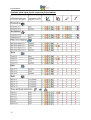
1
User Manual Version V3 An easily operated Finite Elements Program for Windows-, LINUX-, and Mac OS X computers This Freeware Version is the literary property of the Chair for Engineering Design and CAD, University of Bayreuth, Germany, composed and edited by Professor Dr.-Ing. Frank Rieg In collaboration with: Dr.-Ing. Bettina Alber-Laukant; Dipl.-Ing. Daniel Billenstein; Kevin Deese, M.Sc.; Christian Dinkel, M.Sc.; Pascal Diwisch, M.Sc.; Michael Frisch, M.Sc.; Christian Glenk, M.Sc.; Dipl.-Ing. Daniel Goller; Dipl.-Wirtsch.-Ing. Reinhard Hackenschmidt; Stefan Hautsch, M.Sc.; Dipl.-Ing. Claudia Kleinschrodt; Dr.-Ing. Dipl.-Math. Martin Neidnicht; Dipl.-Ing. Florian Nützel; Dr.-Ing. Bernd Roith; Frank Rudolph, M.Sc.; Dr.-Ing. Alexander Troll; Dipl.-Ing. Felix Viebahn; Dr.-Ing. Christoph Wehmann; Dr.-Ing. Jochen Zapf; Dipl.-Ing. Markus Zimmermann; Dr.-Ing. Martin Zimmermann All rights reserved by the editor Version 3 March 2015 is a registered trademark (No. 30 2009 064 238) of Professor Dr.-Ing. Frank Rieg User Manual ABOUT Z88AURORA AND WHAT’S NEW IN Z88AURORA V3 Z88 is a software package for solving structural mechanical, static problems with the aid of the Finite Element Analysis (FEA), which is available under the GNU-GPL as free software with source code. The software, originally created by Professor Frank Rieg in 1986, is currently being further developed by a team of ten under the supervision of Professor Rieg at the University of Bayreuth. In addition to the present compact Z88, which is currently available in the 14th version, an extended program Z88Aurora is on the market since 2009. Z88Aurora is based on Z88 and is available for Windows 32-bit and 64-bit, Linux 64-bit and Mac OS X for free download (as an executable file). In addition to the efficient solvers contained in Z88, Z88Aurora offers a graphic user interface, a completely new preprocessor and an extension of the approved postprocessor Z88O. Developing Z88Aurora great importance was attached to intuitive operation. Since version V2, Z88Aurora offers, in addition to static strength analysis, a material database containing more than 50 established construction materials and modules such as non-linear strength calculations, natural frequency analysis and contact and thermal analyses. The present version Z88Aurora V3 includes an extended nonlinear equation solver, which now also allows to consider non-linear material behavior besides geometrically nonlinear analysis. Therefore, three plastic material laws are implemented. The surface has been enhanced accordingly in order to be able to enter the additionally required material data. Other modules such as a module for transient analysis and one for contact analysis are in development. The modules: Module for thermal analysis In this module of Z88Aurora steady state thermal conduction and the thermal expansion are calculated. The simulated temperature profile is treated separately and is time-independent, i.e. the state of equilibrium is displayed. By linking the thermal and mechanical boundary conditions the user can calculate thermo-mechanical displacements or stress in addition to 3 User Manual the thermal results, like temperature or heat flow. With this, statements can be made about the influence of temperature on the construction component. Module for natural frequency Since Version V2, Z88Aurora also gives the possibility to analyse a component regarding its natural frequency. If the material properties Young´s modulus, Poisson’s ratio and densitiy are known, this module can calculate the natural frequency. Alternatively fixing constraints for sets of nodes in one or several spatial directions can be applied. As a result the user gains information about the smallest natural frequency as well as the distortion of the component. Module Z88NL for non-linear calculation Lastly there is the possibility to conduct non-linear calculations of the structural mechanics. Regarding the boundary conditions homogeneous and heterogeneous displacements, different kinds of applying forces as well as pressure loads can be observed. The equation solver Z88NL evaluates the Finite Element Analysis considering the geometrical nonlinearities or, since V3, also considering non-linear material behavior. With this module the displacements (Z88NLO2.TXT) as well as Chauchy’s stress (Z88NLO3.TXT) can be calculated for the the element types 1 (Hexahedron with 8 nodes), 4 (truss), 10 (hexahedron with 20 nodes), 7 (plain stress element with 20 nodes), 8 (torus with 8 nodes), 16 (tetrahedron with 10 nodes) and 17 (tetrahedron with 4 nodes). With this new Version Z88Aurora V3 three different plastic material laws can be calculated. The Z88 philosophy is also valid for Z88Aurora! - Fast and compact: Developed for PC, no ported mainframe system - full 64-bit support for Windows, Linux and Mac - native Windows and Mac OS X programs, no emulations - Windows and Mac OS X versions use the same computing kernels - full data exchange from and to CAD systems (AutoCAD *.DXF, *.STP, *.STL) - FE structure import (*.COS, *.NAS, *.ANS, *.INP) - context sensitive online-help and video tutorials - simple installation with Microsoft® Installer (MSI) 4 User Manual - Z88Aurora is completely compatible with Z88 V14OS and Z88Aurora V2. Already existing Z88 V13 files or Z88Aurora V1 files can be easily imported with the conversion tool “Mitoo”! 5 User Manual Note: Always compare FE calculations with analytical rough calculations, results of experiments, plausibility considerations and other tests without exception! Keep in mind that sign definitions of Z88Aurora (and also other FEA programs) differ from the usual definitions of the analytical technical mechanics from time to time. Unit conventions are independently managed by the user. The material database integrated in Z88Aurora uses the units mm/t/N. Z88Aurora is a powerful, complex computer program, which is still under development. Please note that currently not all the functions are implemented, therefore certain functions cannot be selected and the modification of parameters in the user interface may show to some extent no effect. How Z88 deals with other programs and utilities etc. hasn’t been tested yet! It is the aim of this research version to give you an understanding of the fundamental operating concept. The developers of Z88Aurora are interested in constantly improving this software. Proposals, suggestions and remarks can be sent to [email protected]. In addition, FAQs are available on the homepage www.z88.de. 6 User Manual LICENSE Software Products: Z88Aurora - Software as delivered, ("Software") Licensor: Chair for Engineering Design and CAD ("LCAD") This is a legal agreement between you, the end user, and Chair for Engineering Design and CAD, Universitaetsstr. 30, 95447 Bayreuth, Germany. By installing, by downloading or by agreeing to the integrated conditions of this End-User License Agreement, you are agreeing to be bound by the terms of this agreement. If you do not agree to the terms of this agreement, promptly return the Software and the accompanying items (including written materials and binders or other containers) to the place you obtained them for a full refund. 1. Grant of license This LCAD license agreement (license) permits you to use a copy of the Software acquired with this license on any computer in multiple number of installations. The Software is in use on a computer when it is loaded into the temporary memory or installed into the permanent memory (e.g. hard disk, CD ROM, or other storage device) of that computer. 2. Copyright The Software is owned by LCAD and is protected by copyright laws, international treaty provisions, and other national laws. Therefore, you must treat the Software like any other copyrighted material (e.g. a book). There is no right to use trademarks, pictures, documentation, e.g. without naming LCAD. 3. Other restrictions You may not rent or lease the Software, but you may transfer your rights under this LCAD license agreement on a permanent basis provided you transfer all copies of the Software and all written materials, and the recipient agrees to the terms of this agreement. You may not reverse engineer, decompile or disassemble the Software. Any transfer must include the most recent update and all prior versions. The Software is for calculation Finite-ElementStructures; there is no warranty for accuracy of the given results. 4. 7 Warranties User Manual LCAD gives no warrants; the Software will perform substantially in accordance with the accompanying documentation. Any implied warranties on the Software are not given. 5. No liability for consequential damages In no event shall LCAD be liable for any other damages whatsoever (including, without limitation, damages for loss of business profits, business interruption, loss of business information, or other pecuniary loss, personal damage) arising out of the use of or inability to use this Software product, even if LCAD has been advised of the possibility of such damages. 7. Governing Law This Agreement shall be governed exclusively by and be construed in accordance with the laws of Germany, without giving effect to conflict of laws. SYSTEM REQUIREMENTS Operating systems: Microsoft® Windows XP, Vista™, Windows 7® or Windows 8.1®, 32- and 64-bit respectively; Mac OS X (ex 10.6); Linux 64-bit. Graphics requirements: OpenGL driver Main memory: for 32-bit 512 MB minimum, for 64-bit 1 GB minimum Documentary and videos require PDF-reader, videoplayer, browser INSTALLATION For more information see the installation guide which comes with the installation of the Z88Aurora package. For starting either use the desktop icon “Z88Aurora V3“ or open the program in the start menu: “Z88Aurora V3” “Z88Aurora V3”. If you haven’t installed the desktop icon nor the start menu entry you can start the program via the Windows-Explorer: “c:\Z88AuroaV3\win\bin\z88aurora.exe”. DOCUMENTATION The Z88Aurora documentation consists of: 8 User manual containing a detailed overview of GUI (Graphical User Interface) Theory manual with an elaborate description of the embedded modules Examples for the most common applications in mechanical analyses Element library displaying the integrated element types in Z88Aurora User Manual 9 Video manual containing some topics of special interest SPIDER-Workflow: Process support by a workflow tool User Manual TABLE OF CONTENTS 1. AN OVERVIEW OF THE USER INTERFACE ............................................................................................... 13 2. MENU BARS .......................................................................................................................................... 13 3. PROJECT FOLDER MANAGEMENT ............................................................................... 15 3.1 CREATING A NEW PROJECT FOLDER .......................................................................................................... 15 3.2 OPENING A PROJECT FOLDER................................................................................................................... 16 3.3 CLOSING A PROJECT FOLDER..................................................................................................................... 17 3.4 PROJECT FOLDER MANAGEMENT IN THE TEXT MENU BAR ................................................................................... 17 3.5 DELETING PROJECT FILES........................................................................................................................ 17 4. VIEW ..................................................................................................................................................... 19 4.1 TOOLBARS .................................................................................................................................................. 19 4.2 CAMERA SETTINGS...................................................................................................................... 21 4.3 COLORS ..................................................................................................................................... 21 4.4 DISPLAYS ............................................................................................................................ 21 4.5 VIEWS AND VIEW OPTIONS .............................................................................................. 23 4.6 LABELS ............................................................................................................................... 23 Labels: Nodes ........................................................................................................................................ 23 Labels: Elements .................................................................................................................................... 24 Labels: Nodes and Elements ................................................................................................................. 24 Hide all labels: Nodes and Elements...................................................................................................... 24 4.7 SIZE OF BOUNDARY CONDITIONS / GAUSS POINTS/ PICK-POINTS ...................................... 24 Size of boundary conditions ............................................................................................................. 24 Size of Gauss Points .......................................................................................................................... 24 Size of Pick-Points ............................................................................................................................. 25 5. CONTEXT SENSITIVE SIDE MENUS ............................................................................. 26 5.1 IMPORT OF CAD AND FE DATA............................................................................................................... 26 Compatibility with other versions of Z88 .................................................................................................... 26 Data Import ................................................................................................................................................. 27 10 User Manual Import Text Menu Bar ................................................................................................................................. 30 Import tool bar ............................................................................................................................................ 31 Import Text Menu Bar ................................................................................................................................. 31 5.2 PREPROCESSOR.................................................................................................................................... 32 Preprocessor in the text menu bar .............................................................................................................. 32 Tool bar Preprocessor ................................................................................................................................. 33 Picking .................................................................................................................................................... 33 Picking of nodes .................................................................................................................................... 34 Picking of elements ............................................................................................................................... 37 Picking of surfaces ................................................................................................................................. 37 How to select the best picking option ......................................................................................................... 38 Set management ................................................................................................................ 39 Creating FE Structures: Trusses/Beams ................................................................................................ 40 Meshing ............................................................................................................................................ 44 U Proof Mesh ............................................................................................................................................ 46 Generating Super elements / mesh generator Z88N ............................................................................. 47 Element parameters ........................................................................................................................ 52 Material ................................................................................................................................................ 56 Applying Boundary Conditions .............................................................................................................. 64 5.3 SOLVER ............................................................................................................................................ 69 The linear Solvers Z88R and Z88RS .............................................................................................................. 69 The nonlinear solver Z88NL ......................................................................................................................... 71 The thermal solver Z88TH ........................................................................................................................... 72 The vibration solver Z88EI ........................................................................................................................... 72 The solver in the text menu bar .................................................................................................................. 76 Available solver types for the respective finite elements ........................................................................... 77 5.4 6. POSTPROCESSOR .................................................................................................................................. 78 TOOLS ................................................................................................................................................... 84 6.1 ANALYSIS............................................................................................................................................. 84 6.2 EDIT STL .............................................................................................................................................. 84 6.3 OPTIONS.............................................................................................................................................. 86 11 User Manual 7. HELP AND SUPPORT............................................................................................. 88 Help ....................................................................................................................................................... 88 SPIDER support ..................................................................................................................................... 95 About Z88Aurora................................................................................................................................... 96 Support ...................................................................................................................................... 96 8. 12 LITERATURE .......................................................................................................................................... 97 User Manual 1. AN OVERVIEW OF THE USER INTERFACE Z88Aurora is characterized by an intuitive operation of the pre- and postprocessor. The project data management is carried out by means of a project folder management. A status display provides better ease of use. Figure 1: User interface of Z88Aurora V3 2. MENU BARS Several menu bars are of importance for operation. The four icon menu bars provide quick access to all functions of Z88Aurora. The main functions of the first icon menu bar, such as preprocessor , open additional side menus. The four main functions "Import", "preprocessor", "solver" and "post processor" are also on the F-keys (F2-F5) available. The other three icon menu bars contain view, color and import options and the functionalities for the preprocessor. The text menu bar contains all functionalities of the icon menu bar and the side menus, the correspondent icons precede the text commands. Depending on the current procedure, there 13 User Manual are several tabs on the tab bar, such as the material cards in the material menu, between which you can switch. Each tab can be closed by clicking the corresponding “X”. The icon menu bar is separated into different areas: the project folder management, the type of analysis and the pushbuttons, which access the context sensitive side menus and the support. Depending on the state of the analysis several icons are displayed in grey, because their functions aren’t available at that time. Figure 2: Pushbuttons of the icon menu bar Please always note the status display at the lower left edge of the user interface. Here you can find references to the next steps and information about operation! Figure 3: Keyboard layout 14 User Manual 3. PROJECT FOLDER MANAGEMENT Depending on the status of the project it is possible to launch a new project folder or to open an existing project. Options which aren’t accessible at the time are displayed in grey. Figure 4: Project folder management of Z88Aurora 3.1 Creating a New Project Folder Create a new folder Enter folder name „Name“ Confirm (Return) Click OK to confirm The input mask disappears and you can start the compilation of the computation model. For further use, the project folder can be put into the quick access! ( Add) 15 User Manual Figure 5: Launching a new project folder 3.2 Opening a Project Folder Select a project folder to open Click "OK" to confirm. The project is displayed in the work area. Figure 6: Opening an existing project folder 16 User Manual Generally it is possible to open the current project folder directly at the GUI with a double click, see Figure 7. Figure 7: Direct file picker 3.3 Closing a Project Folder With this button the presently open project folder is closed. You must always close the current project folder before creating a new one or opening another project! 3.4 Project Folder Management in the Text Menu Bar In addition to the icon menu bar, Z88Aurora possesses a text menu bar above the icon menu bar. This either contains further functionalities or you can access the same functions as in the icon menu bar. The text menu bar with its respective functions is described in the corresponding chapters. Functionalities which aren’t available are displayed in grey. Figure 8: Project folder management in the text menu bar 3.5 Deleting Project Files In the text menu bar there is also the option to delete the complete content of the project folder. The folder itself is preserved. 17 User Manual Figure 9: Deleting project data in the text menu bar 18 User Manual 4. VIEW The view options can be edited in many ways in Z88Aurora. It is possible to display often required tool bars and to change their arrangement, to change the light, material and legend color or to switch miscellaneous additional view options on and off. With “labels” is possible to switch the numeration of nodes and elements on an off. Figure 10: View options 4.1 Toolbars For import/export, view and preprocessor it is possible to show additional toolbars. This can be done permanently via the settings in the file z88enviro.dyn or session-oriented via the menu "View">"Setup". Contrary to Z88Aurora V1 the arrangement of the icons can be completely adjusted to the user’s requirements. For this the default settings of the toolbars are stored in the z88enviro.dyn file with their respective icon number: **Buttons of the toolbars: TOOLBAR 1 1 2 3 4 0 1 0 5 6 7 8 0 9 10 0 11 -1 TOOLBAR 2 1 50 51 52 53 0 54 55 27 0 22 23 24 25 -1 TOOLBAR 3 1 12 13 14 26 0 15 17 16 0 18 19 20 21 0 28 29 0 30 31 0 32 33 -1 TOOLBAR 4 1 19 User Manual 41 42 43 44 45 46 47 48 0 35 0 36 37 64 0 65 0 39 0 40 -1 Figure 11: Extract of z88enviro.dyn In the following figures the default arrangement of the toolbars and their meanings are displayed: Figure 12: push buttons of the second toolbar Figure 13: push buttons of the third toolbar Figure 14: push buttons of the forth toolbar To adjust the toolbar simply arrange the respective numbers. 20 User Manual 4.2 Auto scale 3D Camera Settings offers the possibility to fit the model into the Open GL window. With Rotations a precise rotation can be applied. Z limit towards the user is a clipping option. By setting a defined Z plane the component can be viewed from inside. With all three planes can be used for clipping via the scroll bar. 4.3 Colors The legend color as well as the background color of the Open GL window can be changed arbitrarily. For this, you can resort to defined standards (black/white, white/black, default) or manually set a certain color. The component is adequately displayed via the component color and the light settings. 4.4 Displays There are four possible view options. These can be accessed via the icons in the icon menu bar. Figure 15: Display options in Z88Aurora The view options shaded, surface mesh and mesh can be applied by the user according to his needs; the Picking view is used for the selection of nodes, surfaces and elements. Activating quick view in combination with the display mode “shaded” enables large components to be moved quickly. To improve the display rate of the picking mode in combination with large 21 User Manual components, the Boundary/Solid View can be activated. In this mode only the surface of the component can be selected. The Picking display depends on the previously selected display mode. Thus, you can either select all nodes or only surface nodes! Figure 16: Switching to the display option "Picking", left: surface, right: all nodes 22 User Manual 4.5 Views and View Options Figure 17: View options in Z88Aurora Double clicking on the respective icon or further clicking after the first orientation will rotate the view by 180°. 4.6 Labels The menu item "Labels“ is used to indicate the respective nodes and element numbers of selected objects and contains the following sub items: Labels: Nodes A window appears in which the numbers of the desired nodes must be entered. The dialog is ended with "OK“. 23 User Manual Labels: Elements Similar to "Labels nodes“, the desired element numbers must be entered, in order to display them. Labels: Nodes and Elements This function displays the labels of all nodes and elements. Please keep in mind that this function might make the display of big structures with many elements and nodes confusing and, apart from that, may influence the speed of the program negatively, depending on the hardware used. Hide all labels: Nodes and Elements This function hides the labels of all nodes and elements. 4.7 Size of Boundary Conditions / Gauss Points/ PickPoints Size of boundary conditions The function "Size of boundary conditions“ causes the shown boundary conditions to be displayed enlarged or reduced in the preprocessor menu. Size of Gauss Points With the menu item "Size of Gaussian points“ the size of the calculated Gaussian points, depicted here in the Z88Aurora postprocessor, is defined (Figure 18). Size of boundary conditions 24 User Manual Size of Gaussian Points Figure 18: Display of boundary conditions and Gaussian points Size of Pick-Points The function "Size of Pick-Points“ causes the shown pick-points to be displayed enlarged or reduced in the menu "boundary conditions”. 25 User Manual 5. CONTEXT SENSITIVE SIDE MENUS When you have started a project, you can perform different actions. You can display and alter an existing project, but you can also import a structure from a CAD program as well as from an FE program. 5.1 Import of CAD and FE Data After creating a new project folder it is possible to import geometry data as well as FE structures and to continue using them in Z88Aurora. You will find an overview of the available formats in Figure 18. X X Figure 19: Import and export options in Z88Aurora Compatibility with other versions of Z88 For users who have already worked with Z88V14 OS there is the possibility to import existing Z88 input files into Aurora. In the process, the definition files required by Z88Aurora are created automatically. A more profound insight into the file structure of Z88Aurora is offered by chapter 3 of the Theory Manual. The input files Z88I1.TXT, Z88I2.TXT, Z88I3.TXT, Z88I5.TXT and the mesh generator file Z88NI.TXT can be imported. The file Z88I4.TXT is not required any longer in Z88Aurora. Older projects from Z88Aurora V1 and Z88V13 files can be imported by the migration tool “Mitoo.exe” 26 , which is provided since Aurora V2. It can be found in the “bin” directory. User Manual Double clicking opens the migration dialogue. The files are converted after choosing the respective directory and clicking on “Start”. Figure 20: Migration tool Mitoo For further processing files in Z88V14OS you can insert “enable write_only” in the file Z88.fcd. This creates a complete data set for Z88V14OS in the folder “bin”>“Z88V14OS”. The previous folder is replaced. If you still want to use these files you should save them in another directory. Data Import As an example, the import procedure of a STEP file is demonstrated (Figure 21): X Select Import/Export Click " STEP file“, a selection window is opened Select file Click OK to confirm 27 User Manual Figure 21: Import of a STEP file The default setting determining which input file is supposed to be imported, is defined by the user. The import procedure depends on the quality of the given data. Incomplete or damaged STEP or STL data lead to incorrect displays and faulty meshing in Z88Aurora. In this case it is necessary to adjust the export settings. Depending on the CAD program the lateral length, the interior angle or the width-to-height ratio can be changed. 28 User Manual Figure 22: Import of a STL-file All import features are described in detail in chapter 4.1 of the Theory Manual. Table 1 offers an overview of the model data, which can be transferred from FE structure data. Table 1: model data which can be transferred from FE-structure data AUTOCAD-DXF files can be imported as four different file types (Figure 23). More information about creating an AutoCAD files and their preparation can be found in the Theory Manual, Chapter 4.1.5. 29 User Manual Figure 23: Possibilities to import a DXF-structure The DXF import is designed for files created by the CAD system AutoCAD. If you are using a different program, the import might fail. Import Text Menu Bar Figure 24: Import in the text menu bar 30 User Manual Import tool bar The tool bar “Import” is shown by default. In the menu “View” and “Setup” you can deselect the view option “Import”. Figure 25: Tool bar Import Import Text Menu Bar Figure 26: Export menu A currently loaded FE structure can be written out again using the export function as an STL file. 31 User Manual 5.2 Preprocessor Clicking the preprocessor icon opens the context sensitive side menu "Preprocessor" (Figure 27) you can either create a FE structure or mesh an imported geometry. Afterwards it is possible to select a material from the database or to edit your own material. In addition, all mechanical boundary conditions can be applied. All possibilities of the preprocessor are introduced separately below. Figure 27: Side menu „Preprocessor“ Preprocessor in the text menu bar All functions of the preprocessor can be accessed via the text menu bar. Figure 28: Text menu bar „Preprocessor“ 32 User Manual Tool bar Preprocessor In the menu “View” and “Setup” “Toolbars” you can select “Import” to show the preprocessor buttons: Picking A main innovation in Z88Aurora is the possibility to apply boundary conditions such as forces, pressure and restraints with only one mouse click in the graphic user interface. This will be called “Picking” in the following chapters. For Picking there is a separate view, which can be displayed by clicking the button main window. Figure 29: Picking options in Z88Aurora V3 33 in the User Manual Hot keys With the mouse and a view shortcuts it is possible, to “pick” single or several nodes, elements or surfaces, in order to define the boundary conditions you need: + (click) + (hold) Selecting single nodes New selection of several nodes in a rectangular area while discarding the previous selection. + + (hold) Additional selection of several nodes in a rectangular area while maintaining the previous selection. + (hold) Selecting a rectangular area for deselecting several nodes. The respective nodes, elements and surfaces are marked as small black rectangles. Selecting is carried out by clicking on the rectangles and using the shortcuts. Picking of nodes The Picking of nodes includes the following options: - single nodes - surface (doesnot work with shell elements) - edge - switch - deselect all 34 User Manual Figure 30: Picking of nodes Single nodes: You can select single nodes via the node number as well as adjacent areas. Surface: If you would like to select the interior surface of a drill hole to apply boundary conditions you can use the option “surface”. Pick a node with + (click). With the scroll bar you can choose an angle, which influences the selection. This value describes the angle between the element that contains the selected node and the adjacent element. If the value is smaller or equal the value chosen via the scroll bar, the nodes on these elements will be selected. To find the proper selection for the surface you want to choose, you might have to try some different values in order to achieve the desired result. These settings can be used as a starting point to select the right surfaces (Figure 31): 35 Planar surface: 0.0° A double line of nodes with a large curvature radius: 1° - 2° Lateral surface (complete or partial) with a large curvature radius: 5° - 10° Interior surface of a drill hole: 10° - 20° User Manual Figure 31: Setting of angles Only the selection of a corner node is possible (no nodes in the middle of the element)! Edge: A group of adjacent nodes, which are located on an edge of a FE-model, can be selected via the option “Edge”. With this option it is possible to select nodes on an edge of a drill hole or on a circumferential edge of a profile. Only one node on the edge must be selected. With the scroll bar also only a part of the edge can be selected. Switch: With “switch” the selection is inverted. Deselect: Deselecting of selected areas. 36 User Manual Picking of elements There are following options for picking elements: - surface - all elements - switch - deselect Figure 32: Picking of elements To assign a material it can be advantageous to assign different material properties to different elements. This can be done with “picking of elements” with the normal picking option or with “picking of surfaces”. For rod- and beam-elements the selection of the elements can only be done by using the element number. The elements cannot be selected by the mouse-control. Picking of surfaces There are following options for picking surfaces: 37 - surface - edge - switch - deselect User Manual Figure 33: Picking of elements The option “picking surface” works like the option “picking of nodes”. With both options you can select the surface of a building element. Pick with „surface“. „All surfaces“ selects the entire surface. How to select the best picking option 38 + (click) a surface an select User Manual Set management Every selection done by the picking menu can be saved as a marker. Simply click on “Add” at the marker you would like to save. These markers serve as starting basis for defining sets and later on applying boundary conditions, material assignments, refinements of tetrahedrons or displaying options. With Boolean operators several markers can be added or trimmed. When you achieve the desired result click on “Add Set”. Figure 34: Markers and sets in the picking menu Figure 35: Boolean operation to create a set from a combination of different markers 39 User Manual Creating FE Structures: Trusses/Beams Like in Z88 V14 OS, it is possible in Z88Aurora to create and calculate truss and beam structures. Figure 36: Creating structural elements In the submenu “Creating nodes and elements” nodes are created by entering the coordinates, and then the element type is selected and created. It is not possible to create mixed structures with different element types! To do this, the use of Z88V14 OS is recommended. 40 User Manual Figure 37: Creating structural elements create new node coordinates enter "x“ enter "y“ enter "z“ click After entering the data, the nodes can be edited or deleted: The selection of the nodes to be changed can be done via the selection from the list. 41 User Manual Edit with the node is selected for futher processing in the pop up menu “Edit”. Figure 38: Node menu For further information about the selection of nodes, see chapter " X Picking" X Selecting from the list: U + select the node to be edited from the list the node turns red Afterwards, the selected node can be edited or deleted. When all nodes have been created, the elements can be defined. For this, you have to switch to the menu. With “Add” a node can be inserted in the node list afterwards, the other nodes are renumbered automatically. 42 User Manual Figure 39: menu "Elements" create new element determine element type (Truss No. 4 / No. 9, Beam No. 2 / No. 13 / No. 25, Cam No. 5) for further information please see the Theory Guide enter node 1 (by direct selection of the node via mouse+ enter node 2 (or by entering the node number) ) click After the elements have been entered, they can still be edited or deleted. The selection is done via the element table. The compilation of the entry file is now completed. You can save the data and close the submenu. In the next steps element parameters (geometry, cross section etc.), material and boundary conditions must be allocated. For this, please consult the help for parameters”, “ 43 Material“ or “ Constraints“. X “Element User Manual Meshing You have three possibilities of meshing parts in Z88Aurora. On the one hand, a continuum can be meshed to miscellaneous FE structures with the mesh generator Z88N via the intermediate step of super element creation. On the other hand, two Open Source meshers, TetGen and NETGEN, for the creation of tetrahedron meshes, are integrated in Z88Aurora. It is also possible to convert STL files directly into shell elements. Creating a tetrahedron mesh After import of geometry via *.STEP or *.STL, the part can be meshed by tetrahedrons. Two Open Source meshers are available: TetGen was developed by Dr. Hang Si of the research group "Numerical Mathematics and Scientific Computing" at the Weierstrass Institute for Applied Analysis and Stochastics in Berlin. In Z88Aurora this mesher can be used for tetrahedrons with 4 or 10 nodes. In Z88Aurora this mesher can be used for tetrahedrons with 4 or 10 nodes. NETGEN was mainly developed by Professor Joachim Schöberl (Institute of Analysis and Scientific Computing at the Vienna University of Technology, research group Computational Mathematics in Engineering) within the framework of the projects "Numerical and Symbolic Scientific Computing" and the Start Project "hp-FEM". In Z88Aurora this mesher can be used for tetrahedrons with 4 nodes. In Z88Aurora this mesher can also be used for tetrahedrons with 4 or 10 nodes. 44 User Manual Figure 40: Creating of tetrahedron meshes and the options Tetgen/Netgen Select TetGen or NETGEN determine mesh parameter (accuracy of the mesh) and element type (this value correlates to the edge length in the respective unit of length) click (the rule for meshing is created) The data for the rule can be viewed any time. afterwards either with or add a new rule leave the tetrahedron menu Depending on the selected mesher, the mesh creation may take some time. Please note the information window "meshing" and the status display! Chose the accuracy of the mesh adequately to the size of your component. 45 User Manual U Proof Mesh As an additional function there is the feature "proof mesh" for the quality check of imported or self-created meshes. Please keep in mind that the results of the FE calculation are only plausible when you have a sufficiently good mesh. Therefore always conduct a quality check at the end of the meshing. If the mesh is faulty the flawed element is displayed in red (view option: “mesh”). Additionally the file z88det.txt is created in the project folder. Figure 41: Prove mesh 46 User Manual Generating Super elements / mesh generator Z88N The mesh generator Z88N from Z88 is integrated in Z88Aurora with additional features: Z88N for hexahedrons, tori, plain stress elements, plate and volume shells Tetrahedron refiner Shell thickener → Volume shell STL refiner These features are openend with the icon in the preprocessor menu Figure 42: menu “Preprocessor” with the start icon “Super elements” of the mesh generator Z88N 47 User Manual Usage of Z88N in Z88Aurora The mesh generator can create 2 or 3 dimensional FE structures from super structures. Generating a mesh is only possible with continuum elements. Table 2 offers an overview of the possible FE structures. Table 2: Overview of possible super structures in Z88Aurora Super structure Finite Element Structure Plane Stress Element No. 7 Plane Stress Element No. 7 Torus No. 8 Torus No. 8 Plane Stress Element No. 11 Plane Stress Element No. 7 Torus No. 12 Torus No. 8 Hexahedron No. 10 Hexahedron No. 10 Hexahedron No. 10 Hexahedron No. 1 Hexahedron No. 1 Hexahedron No. 1 Plate No. 20 Plate No. 20 Plate No. 20 Plate No. 19 Shell No. 21 Shell No. 21 In all spatial directions a super structure can be refined uniformly, in ascending or descending order. For this element sets must be created, the rules for meshing must be defined and afterwards meshed. For example: Define 3 element sets, change to Define element type local x-direction: uniform, ascending or descending fragmentation local y-direction: uniform, ascending or descending fragmentation local z-direction: uniform, ascending or descending fragmentation 48 User Manual click on (the rule for meshing is created) The data for the rule can be displayed any time. either or create another rule; only one rule can be defined per set leave the menu with Figure 43: menu “Super elements” of the mesh generator Z88N After creating the mesh, the rules for meshing are deleted! 49 User Manual Refining a tetrahedron mesh With this option it is possible to improve already existing tetrahedron meshes. With “picking” a set can be created with the tetrahedron that should be refined. Each element is divided into 8 tetrahedrons. Figure 44: refining of a tetrahedron: input mask (right), process (left) The adjacent elements are adjusted to the changed node numbers and are divided as well. For this a minimum element angle must be specified to prevent a large deformation. Instead of the ideal interior angle of 60°, an angle of 3°-10° is realistic. 50 User Manual Figure 45: Process of the algorithm for refinement Shell thickener With this feature it is possible to thicken already existing shells, which have nodes in only one plane (e.g. from Nastran or DXF import), and thus creating volume shells (element No. 21 and No. 22) Figure 46: normal shells (above) and volume shells (below) 51 User Manual Figure 47: Shell thickener in Z88Aurora More information see “ Creating a tetrahedron mesh“ Element parameters You can allocate element parameters for the element types plate, shell, truss, beam and cam element and plain stress element. According to the element types following icons are selectable: : beam, truss, cam : plate, plain stress element, shell beam, truss, cam If you have created these structures beforehand, they can be edited here. Element parameters of imported Z88 files (Z88V14, Z88V13, Z88Aurora V1) must be created anew, because they cannot be imported with the structure! Depending on what element type you have chosen, you can assign the respective geometry date. You can assign one geometry to all elements (from/to element) and assign one geometry per section. 52 or you can define sections User Manual Figure 48: Assigning cross section in the menu “element parameter” When using the element type 25, another menu is available, which need special settings for the control node can be made. For details, see theory manual. The element parameters can be inserted by hand. Additionally Z88Aurora V3 can calculate the element geometry of a circle, tube, rectangle, square profile or I-profile. 53 User Manual Figure 49: Cross sections that can be automatically calculated 54 User Manual To do this: select element geometry insert entry parameters (depending on the selected element type only the required data is used for the calculation) With the element parameters are assigned to the structural elements. Plate, plain stress element, shell You can assign one geometry to all elements or you can define sections (from/to element) and assign one geometry per section. edit thickness with double clicking Figure 50: Assign thickness to plain stress elements, plates and shells 55 User Manual Material In order to carry out static strength analyses, natural frequency analyses and thermic calculations the present version of Z88Aurora offers a material database containing more than 50 established construction materials. Z88Aurora Material Database The Z88Aurora material database is selected in the preprocessor menu ( ) via the button (or via "Preprocessor" “Material Database”). To facilitate your work with Z88Aurora, several materials, such as miscellaneous types of steel and aluminum, have already been predefined. If you select a material from the list on the left, its allocated properties can be viewed in “Details” (Figure 51). If a material should be edited, a copy of the material is created so that the internal data base remains consistent. The flow curves are not copied by non-linear material. Already existing materials from other projects can also be imported. Figure 51: Z88Aurora Material database If the required material is not included, you have the possibility to define new materials in the database. For this, click in the right menu and the context menu "Material Parameters" is opened (Figure 52). In the first input array you can define the material type by means of "Material Name", "Identifier" and "Material Number". In the second input array 56 User Manual the material properties, such as Young's Modulus, Poisson's ratio and density ( Unit density: t/mm³) are entered for the linear analysis. Figure 52: Context menu material parameters In the case of unalloyed construction steel (according to DIN EN 10025-2) this would look as follows: 57 Name: construction steel (common name) Description: S235JR Number: 1.0038 Annotation: own annotations e.g. delivery Young's Modulus: 210000 N/mm² Density: 7.85 E-9 t/mm³ Poisson's Ratio: 0.29 User Manual For thermal analysis you have to assign heat conductivity and heat expansion (tab “Thermal”, cp. figure below). Figure 53: Input for thermal analyses Figure 54: Context menu material parameters II Only the material properties required by the respective type of analysis have to be entered. 58 User Manual Please note that you have to enter a dot as decimal point and that the material name must be unique (e.g. "construction steel1“, "construction steel2“, etc.). With the pushbutton you can edit already entered materials. A copy of the material is created so that the data base remains consistent. Define With Delete the material is added to the structure, with it is deleted. If you want to apply one material to the whole structure, set a check mark at “All elements”. Otherwise you can apply different materials to different elements sets, e.g. to create a Close bimetal. With the data base is saved and the tab is closed. Materialmodels In nonlinear analyses different material laws can be chosen to consider elastic or plastic material behavior. Table 3: Overview of material models material behavior Young´sModulus Hooke linear-elastic Von Mises elastic-plastic Wehmann elastic-plastic, different poisson ratio in plastic sector Poisson Ratio Flow curve Further parameter • flow direction parameter w or • course of the flow direction parameter f(w) Therefore, the table with the assigned materials contains an additional column in the module nonlinear strength. Figure 55 shows this column, in which the favored material law can be selected. This selection has to be confirmed with the "ENTER" button so that it is adopted. In case of Hooke's law, linear-elastic material behavior is present, geometric nonlinearity alone will be taken into account. Regarding the material parameters, only Young´s modulus and 59 User Manual Poisson's ratio are necessary in this case. These two parameters are specified under the “Linear” tab (see. Figure 52). Figure 55: Choice of the material law for nonlinear analyses By selecting one of the other laws, plastic material behavior is present and additional material data must be specified. In these cases, no geometrical non-linearities are taken into account. Necessary additional parameters for the plastic material models must be specified under the “Non-linear” tab. Figure 56 shows which parameters must be entered for the "von Mises" law. You have to enter the flow curve, which is defined by pairs of values of the plastic elongation and yield stress. By clicking the button “Add” you can define a new pair of values, the values can always be selected and edited by double-clicking. With the “Delete” button the selected value pair is deleted. Also, importing a text file with all pairs of values is possible. 60 User Manual Figure 56: Input of the material data for the material law "von Mises" Figure 57 shows the structure of a sample file. After its import, the values result in the way shown in figure 56. It is important that the first line of the file contains the number of pairs of values. Figure 57: Structure of a txt-file for the import as yield curve The unit for the plastic strain is always 1 (dimensionless), i.e. 0.05 corresponds to 5% plastic strain. The flow curve can be determined by the following two equations from the Stressstrain curve (σ-ε diagram). Thereby, is the yield stress and ε the total strain. Figure 59 shows an exemplary stressstrain diagram and the corresponding flow curve. Flow curve Flow stress kf / N/mm² Stress σ / N/mm² Stress-strain diagram 900 800 700 600 500 400 300 200 100 0 0 0.025 0.05 Total strain ε / 1 0.075 0.1 900 800 700 600 500 400 300 200 100 0 0 0.025 0.05 0.075 Plastic strain εpl / 1 Figure 58: Stress-strain diagram and the corresponding flow curve 61 0.1 User Manual In case of the Wehmann model, the selection must be switched to " Wehmann (w constant)” as shown in figure 59 on the left. This model allows to adjust the transverse contraction in the plastic range decoupled, with the help of an additional material parameter. If you, for example, notice that the von Mises-law does not describe the transverse contraction correctly, you can achieve an improved description with the help of the Wehmann model. For Wehmann model, as for von Mises, a yield curve must be specified. Figure 59: Input of the material data for the material law „Wehmann model“ In addition, the flow direction parameter w has to be specified, which can assume values between 0 and 1 (see. figure 59 right). The parameter can be determined in a tensile test, by including the measurement of the transverse contraction. Using a circular sample having a diameter the cross-sectional area and length results in the following determinative equation. and are the change of diameter and the change of length. Note that and identified. are applied. With Young's modulus (elastic) Poisson's ratio are is the force in the tensile test. Further information on Wehmann model can be found in [Wehm14]. 62 and User Manual In case that the parameter according to the equation above for tensile test data is not constant, the modified Wehmann model exists. Once the selection is switched to " Wehmann (w variable)", the additional material parameters can be entered (see. figure 60). Figure 60: Input of the material data for the material law „modified Wehmann“ Entering the course of the w parameter is similar to the input of the flow curve (see figure 60 right). Again, a file can be imported with the value pairs. The file has the same structure as the one for the flow curve (see figure 57), only the parameter must be entered instead of the yield stress, respectively. Thereby the parameter is determined according to the equation below from tensile test data. With the plastic transverse strain is denoted. The following applies: So the course of the plastic transverse strain plotted over the plastic elongation is to be determined from the tensile test. The gradient of this curve corresponds to the w-parameter. Also applies here. For further information on the theoretical background of modified Wehmann model we refer to [Wehm14]. 63 User Manual Applying Boundary Conditions Z88Aurora offers the possibility to define all boundary conditions within the preprocessor. Boundary conditions can only be applied to sets, so first of all these have to be defined with (for more information see chapter „Picking“) Figure 61: Picking options for boundary conditions Imported structures can either be calculated with the existing boundary conditions in Z88Aurora or new entries can be applied. For imported boundary conditions sets are created automatically, that can be viewed in boundary conditions menu. For both types of analysis and two different views of the menu are available, that can be selected in the upper left corner of the menu. 64 User Manual Figure 62: Creating boundary conditions I In order to apply a boundary condition, proceed as follows: Select analysis type Select set Select Directions/Rotations, e.g. x-direction Select type, e.g. “Displacements” Enter value, e.g. “0” Enter name, e.g. “fixed” Add In the OpenGL window the boundary condition appears with the respective color. 65 User Manual Figure 63: Creating boundary conditions II Figure 63 shows the possibilities to apply boundary conditions. You can apply displacements, pressure and forces. You can choose between uniformly distributed force, surface load, projected surface load, line load and projected line load. Force (uniformly distributed) applies always the same force to the nodes while Surface load and Line load distributes the load according to FEA rules (for further information see theory manual) Thermal boundary conditions are not dependent on direction! Pressure always requires a surface-set. 66 User Manual Delete deletes existing boundary conditions. “Show all” shows the boundary conditions, which are activated via the check mark. The different boundary conditions are shown in their respective color: Figure 64: view options “boundary conditions“ To view single boundary conditions separately, the respective constraint can be selected via "Administration". Figure 65: viewing boundary conditions separately Close With 67 the menu is closed. User Manual Size of boundary conditions The function "Size of boundary conditions" effects that the shown boundary conditions are displayed at a larger or smaller scale in the preprocessor menu. Figure 66: Changing the size of boundary conditions The labeling of the boundary conditions is not scaled by the size of the component. If you do not see applied boundary conditions, please change the size via the tool bar "View" or the sub item "Size of boundary conditions" in the "View" menu. 68 User Manual 5.3 Solver The solver is the heart of the program system. It calculates the element stiffness matrices, compiles the total stiffness matrix, scales the system of equations, solves the (huge) system of equations and stores the displacements, the nodal forces and stresses. The linear Solvers Z88R and Z88RS Z88 features three different solvers: A Cholesky solver without fill-in. It is easy to handle and very fast for small and medium structures. However, like any direct solver Z88F reacts badly on ill-numbered nodes but you may improve the situation with the Cuthill-McKee program Z88H. Z88F is your choice for small and medium structures, up to 20,000 ... 30,000 degrees of freedom. A direct sparse matrix solver with fill-in. It uses the so-called PARDISO solver. This solver is very fast but uses very much dynamic memory. It is your choice for medium structures, up to 150,000 degrees of freedom. A sparse matrix iteration solver. It solves the system of equations by the method of conjugate gradients featuring SOR- preconditioning or preconditioning by an incomplete Cholesky decomposition depending on your choice. This solver deals with structures with more than 100,000 DoF at nearly the same speed as the solvers of the large and expensive commercial FEA programs as our tests showed. In addition, a minimum of storage is needed. This solver is your choice for large structures with more than 150,000 … 200,000 DoF. FE-structures with ~ 5 million DoF (degrees of freedom) are no problem for it if you use a 64-bit operation system (Windows or Linux or Mac OS X) along with the 64-bit version of Z88 and about 6 GByte of memory. This very stable and approved solver works always, so you may use it as your standard solver. 69 User Manual Figure 67: solver menu linear mechanical analysis Accelerated versions of the linear solvers were already added to Z88Aurora V2b. Some steps in the solution process could be reduced, without compromising the quality of results. In particular, the two variants of the CG iterative solver were parallelized, thereby not only one CPU but any number can be used simultaneously. Therefor it requires twice as much memory as the CG-solvers from Z88R. Further, the termination criterion for the mathematical residual is now used, which includes the Euclidean norm of the error vector. This threshold corresponds to the root of the termination criterion of the Z88R. Even with the boundary conditions and other task-phase modifications were made, so that the already parallelized Pardiso solver could be accelerated too. All changes are marked as Z88RS and are used when a check mark is set for "Solver Speedup". The following Table 4 should serve for orientation when each solver can be used. 70 User Manual Table 4: Overview solver Solver Type Number of DoF Required Memory Speed Multi -CPU Notes Z88R -t/c choly Cholesky Solver without Fill-In up to ~ 30,000 medium medium no only for trusses and beams in Z88Aurora V2 Z88R -t/c parao direct Solver with Fill-In up to ~ 150,000 with 32-bit PCs very high very high yes useful with several CPUs and very much memory Z88R -t/c -siccg or -sorcg conjugated gradients solver with preconditioning no limits (tested with more than 12 Mio. DoF on a normal PC) an absolute minimum no a very stable and reliable solver for very large structures medium Z88RS -t/c -parao direct Solver with Fill-In up to ~ 150,000 with 32-bit PCs very high maximum yes Z88RS -t/c -siccg or -sorcg conjugated gradients solver with preconditioning no limits (tested with more than 12 Mio. DoF on a normal PC) very low high yes once more accelerated version of the direct Pardiso Solver from Z88R requires twice as much memory as the CG-solvers from Z88R and enables several CPUs The nonlinear solver Z88NL The module Z88NL represents a solver for nonlinear calculation. Nonlinearities can either be geometrical origin or material nonlinearities, for which the stress-strain relationships are nonlinear. Regarding the material properties Young’s modulus and Poisson’s ratio are required for pure geometrical nonlinearity, just like for the linear solver Z88R. For material nonlinearities additional data such as the flow curve have to be specified (see section 5.2). The same boundary conditions as in the linear mechanical calculation can be applied. Following elements can be handled with geometrical nonlinearity: Type 1 (hexahedron with 8 nodes), type 4 (3dimensional truss), type 7 (plain stress element with 8 nodes), type 8 (torus with 8 nodes), type 10 (hexahedron with 20 nodes), type 16 (tetrahedron with 10 nodes) and type 17 (tetrahedron with 4 nodes). Type 1 and type 16 can be used for material nonlinearities. The main difference to linear calculation is the parameterization of the solvers, which are described in detail in the theory manual. Also the postprocessor is different: Now results for every load step are available. This affects both the node based results of displacements and the integration point based stress results. For stress results the comparison stress is calculated after the von Mises yield criterion, which is based on Cauchy stress. 71 User Manual The thermal solver Z88TH For the calculation the module for steady-state thermal simulation resorts to the solver types Pardiso, SORCG and SICCG. The number of values used in the system of equations is decreased by using the finite elements for pure thermal analysis (hexahedrons, tetrahedrons) because of the reduction of the DoF to one (instead of three), so the system of equations itself is reduced. In contrast there are no changes in the thermo-mechanical calculation, the usual three DoF have to be regarded. The thermal conductivity is the only material property that is required for determining the steady-state thermal conduction. If a thermo-mechanical simulation is to be conducted the coefficient of thermal expansion is also needed (in addition to the material properties used in elastostatic problems: Young’s modulus, Poisson’s ratio). No additional adjustments have to be done for a thermo-mechanical calculation. The solver Z88TH automatically conducts the desired simulation, if thermal and mechanic boundary conditions have been applied. If only thermal boundary conditions are applied a steady-state thermal calculation is conducted. The vibration solver Z88EI The module for natural frequency uses a numeric method, which is especially approved in FEA and was introduced already in 1950 by Cornelius Lanczos. Although no one could have thought about numeric modal analysis then, the algorithm possesses many advantages for FE programing. The basic idea, to reduce the matrix to a tridiagonal matrix (non-zero elements only in the main diagonal and the first diagonal below and above) by iteration is very effective regarding memory management. Additionally it is guaranteed mathematically, that the eigenvalues of this tridiagonal matrix are approximately equal to the eigenvalues of the original matrix. Each iteration of the solver can be divided into two stages. Initially an additional row or column of the tridiagonal matrix is calculated – basically only three matrix values, because all previously calculated entries preserved. In the second stage the eigenvalues of the matrix are determined – starting at zero and sorted in ascending order. 72 User Manual Further information and theoretical background on the solvers can be found in the theory manual. The solver types are selected via the solver menu, depending on the type of analysis the solver menu is adjusted. Under “failure theory” the following comparison stresses can be selected, depending on the preceding calculation: - von Mises theory - Rankine’s theory / principal stresses - Tresca’s theory Additionally a view control values for the respective solver have to be defined in the menu solver” “solver parameters” - Termination criterion: maximum number of iterations (e.g. 10000) - Termination criterion: residual vector < Epsilon (e.g. 1e-7) - Parameter for convergence acceleration: shift factor Alpha (between 0 and 1, good values may vary from 0.0001 to 1; start with 0.0001). - Termination criterion: maximum number of iterations (e.g. 10000) - Termination criterion: residual vector < Epsilon (e.g. 1e-7) - Parameter for convergence acceleration: relaxation factor Alpha (between 0 and 2, good values may vary from 0.8 to 1.2). 73 User Manual Non-linear mechanical Figure 68: Solver menu non-linear calculation Calculation of equivalent stress with Z88NL is only possible with von Mises theory. New in version V3 (see figure above, bottom left) is the possibility of spring back calculation. This is provided for calculations with the plastic material laws. If the hook is set, the number of steps for the spring back calculation can be determined. With five steps chosen, for example, the load is reduced at the end in 20% increments from 100% to 0%. 74 User Manual Figure 69: Solver menu steady-state thermal calculation The settings correlate to those of the linear mechanical calculation. Figure 70: Solver menu natural frequency 75 User Manual - Number of frequencies that are calculated Termination criterion: maximum number of iterations (e.g. 10000) Termination criterion: residual vector, eigenvalue remains constant Difference between two frequencies: Difference between two eigenvalues (if the difference is smaller, the eigenvalues cannot be distinguished) - Block length Kappa: critical value; after this number of iterations the residual vector is checked After defining of all required parameters the calculation is started with. When the calculation is finished, an information window is opened automatically. Figure 71: Information window The solver in the text menu bar The solver can also be accessed via the text menu bar: Figure 72: Selecting the solver via the text menu bar 76 User Manual Available solver types for the respective finite elements 77 User Manual 5.4 Postprocessor After the calculation has run, the results can be displayed in the Z88Aurora postprocessor by clicking the button . Figure 73: Z88Aurora Postprocessor On the right side of the screen a context menu appears. Here it is possible to have the component displayed in the results window in various ways: deflected, undeflected or both at the same time. Below there is the results menu: the displacements (component-by-component and as value) as well as the stresses (at the corner nodes, averaged by elements and at the Gauss points) can be shown, the Gauss point display, however, is only shown in an undeflected condition. 78 User Manual Figure 74: Color scale Figure 75: Menu bar Post-processor Under "Postprocessor Output data“ you can access the single output files of the calculation, in order to get the exact numerical values (for further information see Z88Aurora Theory Manual): 79 User Manual Figure 76: Output files 80 Z88O0.TXT – prepared input data Z88O1.TXT – prepared boundary conditions Z88O2.TXT – calculated displacements Z88O3.TXT – calculated stresses Z88O4.TXT – calculated nodal forces Z88TO0.TXT – calculated temperature Z88TO1.TXT – calculated heat flow Z88TO2.TXT – calculated thermal expansion Z88TO3.TXT – calculated thermal forces Z88TO4.TXT – calculated displacements Z88TO6.TXT – calculated nodal forces (thermo-mechanic) Z88TO7.TXT – calculated stress (thermo-mechanic) Z88NLO2.TXT - calculated displacements, nonlinear calculation with Z88NL Z88NLO3.TXT – calculated Cauchy-stress, nonlinear calculation with Z88NL User Manual In addition to the results data in a text file *.txt, where all nodes-, element- or Gauss pointinformation are stored, since version Z88Aurora V2b it is possible by user-defined node- or element-sets (“Pre-processor Picking”) to write out the results of a specific component range. Therefore you have to choose “Export data” in the menu bar post-processor (figure 68). Afterwards a new menu pops up, where on the right hand all sets are listed. These include the sets that were created automatically and the sets that have been created individually. Figure 77: Export of results If you choose one set, for example the node-set “Fixed” on the right hand, on the left hand there will be the minimal/maximum displacements, the minimal/maximum/average stress and the minimal/maximal/average/sum of the forces illustrated. Figure 78: Results of the node-set “Fixed” 81 User Manual By selecting the button “Settings” (see figure 69) the user can decide individually which kind of export data of the chosen set should be written in a *.txt-file or a *.csv-file (figure 70). Figure 79: Individual outpout data This is done by checking the corresponding output data set on the left side. Furthermore, the user can set the separator (space or semicolon) and the decimal separator for the output data (Please note which language setting the data processing software such as MS Excel, has!). For the node-set “Fixed” with all selected output data the table looks like figure 73, for example: Figure 80: Example of a Postinfo file The file itself will be saved automatically in the project file directory, it is called PostInfo_Fixed.csv (the name is a combination of PostInfo and the set-name). It can be seen that the type of the output file Fixed is Nodes with a number (count) of 745 nodes. The following table 4 shows the shortcuts of the output data file. 82 User Manual Table 4: shortcuts of the Postinfo file Nr number X x-coordinate Y y- coordinate Z z- coordinate disX displacement in x-direction disY displacement in y-direction disZ displacement in z-direction disMag total displacements Fx forces in x-direction Fy forces in y-direction Fz forces in z-direction Fmag total forces stress stresses It is also possible the currently displayed deformed structure to save as an STL file. This is available for all element types except the structural elements (type 2,4,5,9,13 and 25). 83 User Manual 6. TOOLS 6.1 Analysis For exact analysis of an FE-mesh or an imported model you can get information about nodes, elements and surfaces via “Analysis”. You select in the respective picking menu the object and go to “Tools”>”Analysis”. With “measuring” you can view the special orientation of two nodes. Figure 81: Tool for analysis 6.2 Edit STL Switched surfaces in STL-import files, that cause a meshing abort, can be repaired via the tool “edit STL”. To do this select “Edit STL” in the “Tools” menu. the switched surfaces are displayed in red click on one (!) green element 84 User Manual confirm with “Yes” Figure 82: Edit STL 85 User Manual 6.3 Options Changes in the user interface can be done in the menu “Options”. Here you can select the language, the data folders, the memory settings and the view options. Figure 83: Options The global settings for CPU and memory selected here are independent from the local settings in the solver options menu. The changes only take effect after rebooting Z88Aurora! - Media Player Selecting the media player with which you can play the instruction videos. e.g. Windows Media Player; „C:\ Program Files \Windows Media Player\wmplayer.exe “ 86 User Manual - Browser Selecting the browser with which you can view the homepage and the user forum directly from Z88Aurora e.g. Internet Explorer; „C:\ Program Files \Internet Explorer\iexplore.exe“ - PDF-Reader Selecting the PDF reader with which you can open the Z88 user manual and theory manual e.g. Adobe Acrobat Reader; „C:\Program Files\Adobe\Reader 9.0\Reader\AcroRd32.exe“ The dialogue and the information windows are closed with “OK”. Afterwards you can restart Z88Aurora. 87 User Manual 7. HELP AND SUPPORT Help Z88Aurora offers you several different help functions, which can be used separately. Following is an overview of the separate help components. The icon in the icon menu bar opens the popup menu for the selection of the single help modules. Figure 84: Help options Video manual To make learning easier, video sequences dealing with some special topics are available. The videos are accessed via the menu "Video manual". 88 User Manual Figure 85: Video manual in Z88Aurora These are: Picking Views Node information User Manual In the User Manual all functions available in Z88Aurora are explained. Theory Manual The Theory Manual addresses the issue of the computation bases of Z88Aurora. For experienced Z88 V14 users the differences between Z88 V14 OS and Z88Aurora are presented. Furthermore, all input and output files as well as the element types are illustrated in detail. The modules which are accessed from the user interface are explained here. Element Library A short description of the element types integrated in Z88Aurora. 89 User Manual Examples By means of different examples the basic functions are explained. Plane elements: Example: fork wrench As an example, a DXF-file from AutoCAD was chosen– a fork wrench as plane stress element. By means of this component the export procedure of the structure from the CAD program as well as the import of DXF-files into Z88Aurora is demonstrated. Furthermore, the creation and finer meshing of super structures is illustrated, as well as the execution and evaluation of a linear strength analysis. Volume elements: Example: engine piston As already described in previous chapters, you can import data from 2D- and 3D-CAD- and FE-systems in Z88Aurora. The example cited here is an engine piston; it was designed in PTC Pro/MECHANICA and saved as a NASTRAN file. By means of this component, the import of the NASTRAN format and the calculation of tetrahedron meshes in Z88Aurora are demonstrated. Shell elements: Example: square pipe To display thin walled structures, such as bent sheet metal parts or profiles, shell models can be used. The component employed here is a square profile, which was designed as a shell model with an external FE program and saved as NASTRAN file together with the boundary conditions. By means of this component the import and the calculation of shell models in Z88Aurora are demonstrated. Truss elements: Example: crane girder A simple example with 20 nodes and 54 trusses forming a spatial framework. These structures can easily be entered manually, CAD programs won't help much. Just try it for yourself. 90 User Manual Volume element: Example: Two-stroke engine piston A piston for a two-stroke engine should be calculated. The load is the combustion pressure of 42.5 bar, the gudgeon pin is defined as bearing. The piston was designed in the 3D CAD program Pro/ENGINEER and meshed – selecting linear tetrahedrons - with Pro/MECHANICA. Then the structure and the mesh were exported as NASTRAN file. The piston contains 3211 nodes, thus 9633 degrees of freedom and 12489 elements (tetrahedron type 17 with 4 nodes). Tetrahedron elements: Example: motorcycle crankshaft Applying a piston load of -5,000 N a single cylinder motorcycle crankshaft is to be calculated. In this case the constraints have to be considered in a special way, which is kind of tricky. Plane stress element: Example: gearwheel l A gearwheel, whose center is pressed on a shaft, is examined. The interference fit assembly's groove pressure is 100 N/mm². Crucial point is the deformation transmitted by the center's expansion to the gear teeth (which are left out for model simplification). Plate element: Example: circular plate This sample is intended as an introduction for plate calculation. Z88 contains plate elements (Reissner-Mindlin approach) with 6-node Serendipity elements (type 18), 8-node Serendipity elements (type 20) and 16-node Lagrange elements (type 19). Nevertheless the plate is a 2D element. With plates thus being 2D elements the calculation requires some skills to map this paradox in FE software. 91 User Manual Hexahedron elements: Example: plate segment A three-dimensional plate segment with curvilinear hexahedrons is calculated. Though seeming simple, this example can barely be solved analytically. It's a valuable sample for experiments with the mapped masher. Creating a structure and element parameters: Example: gear shaft In Z88Aurora an editor for creating beam and truss elements is included. The required nodes for creating the structure can be entered by using coordinates; the coincidence is created via the graphic user interface. This is explained using an example of a gear shaft. Shell thickener/Clipping Example: submarine A submarine, which was constructed in Pro/ENGINEER as shell structure is imported with the NASTRAN interface and thickened to create a volume shell in Z88Aurora. The displacements and stresses in the submarine’s hull should be calculated in the case of a dive depth of 50 m. The submarine is supposed to float in the water, thus it is fixed in Z88Aurora via a virtual fixed-point. ABAQUS-import/line load Example: 3D gear In this example a gear, which was imported as ABAQUS INP file, is calculated. This is done with a static load, so it cannot replace a strain calculation according to DIN 3990. The gear in this example is an involute spur gear without any deviations in the tooth flank. The gear body is constructed out of ribs to save weight. 92 User Manual Natural frequency Example: Drum A popular example natural frequency analysis is the oscillating drumhead, because it can be calculated analytically as well. This is an example for pure natural frequency, because the drumhead achieves steady-state (final tone) only after one stroke because of the equilibrium between mass inertia and reset force. The fixing of the drumhead at the frame allows only certain modal form vectors, which can be described with mathematical methods. These form vectors should be simulated in FEA as well. Thermo mechanics Example: Spoon As example for heat flow and temperature analysis a spoon, which is hold with one hand and used for eating soup, should be simulated. The spoon was constructed in Pro/ENGINEER and imported as .stl-file into Z88Aurora and was then meshed. At the handle the temperature is defined by the temperature of the hand, the heat flow through the handle is caused by the heat of the soup. Geometric nonlinearity Example: Hinge In this example a hinge to lock a cylindrical truss in position is examined. The clamping force is very high, so there are great deformations. Material non-linearity Example: Ball coupling In this example, a heavy loaded ball coupling is considered. These couplings are used in agricultural engineering. In the notches, plastic deformations occur, so that taking plasticity into account leads to significantly improved stress results. 93 User Manual Material non-linearity Example: Tensile test This example deals with the simulation of a tensile test with the different material models which can be chosen. The models are compared to each other in order to explain the differences. 94 User Manual SPIDER support To achieve clearly arranged settings and functionalities for the user, the proceeding of FEA is displayed within the SPIDER work flow tool. Help can be accessed via the F1 key. You can choose between two different types of user support: the work flow scheme or additional videos, explanations or decision propositions. Figure 86: Work flow support SPIDER in Z88Aurora 95 User Manual About Z88Aurora Figure 87: Information about Z88Aurora Support Homepage See www.z88.de for further information! Email If you need support: [email protected]! 96 User Manual Forum On the homepage you can find a forum where you can discuss Z88 topics and issues with other users. For Development news on Z88Aurora All duplication rights remain with the Chair for Engineering Design and CAD; author: Dr. B. Alber-Laukant 8. LITERATURE [RHA14] [Wehm14] 97 Rieg, F.; Hackenschmidt, R.; Alber-Laukant, B.: Finite Element Analysis for Engineers. Basics and Practical Applications with Z88Aurora. 1st english edition, Carl Hanser, Munich, Vienna, 2014 C. Wehmann: Nichtlineare Finite-Elemente-Analyse für Berechnungen im Maschinenbau. Geometrische Nichtlinearitäten und plastisches Materialverhalten ausgewählter Maschinenelemente. PhD Thesis, University of Bayreuth, Shaker, Aachen, ISBN 978-3-8440-3063-1, 2014