1
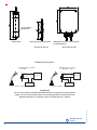
Betriebsanleitung
Operating instructions
Instructions d`utilisation
Pegelsonde
Level probe
Sonde pour puits
Typ:
BS
08/2010 Art.-Nr.:400835-DB922047
MANFREDJÜNEMANN
Mess- und Regeltechnik GmbH
Max-Planck-Str. 49
D-32107 Bad Salzuflen
Tel: +49 (0)5222 / 80768-0
Fax: +49 (0)5222 / 80768-20
www.juenemann-instruments.de
eMail: [email protected]
Quality for the
future
Schutzkappe
Polyamid
Pegelsonde
Aufhängung für Pegelsonde
Kabelgehäuse IP 67 mit atmosphärischer Belüftung
Bestell-Nr.:405 781
Bestell-Nr.:101 524
Elektrischer Anschluss
Ub+/S- 1
Pamb
L+
Versorgung
Ub-/S+ 2
M
Ub+
1
L+
Ub-/S- 2
M
In-
4
In+
S+
PE
4
Versorgung
3
In-
Pamb
Kabelanschluss, 3-Leiter
0 ... 20 mA, 0 ... 10 V
In+
Kabelanschluss, 2-Leiter
4 ... 20 mA
PE
Verbraucher
1: weiß, - 2: grau, - 3: grün - 4: gelb.
Verbraucher
1: weiß, - 2: grau, - 3: grün - 4: gelb.
!! Achtung !!
Das Anschlusskabel mit Kapillarrohrbelüftung darf nicht gequetscht oder geknickt
werden, da sonst der Druckausgleich zum Umgebungsdruck unterbrochen wird.
Mindestbiegeradius: festverlegt = 20mm / flexibler Einsatz = 100mm
2
08/2010 Art.-Nr.:400835-DB922047
Quality for the
future
1.0 Elektrischer Anschluss
Der elektrische Anschluss wird über ein abgeschirmtes Kabel mit Kapillarrohrbelüftung hergestellt.
Die genauen Anschlussbelegungen können den Zeichnungen entnommen werden.
Ferner sind Anschlussbelegung und die erforderliche Hilfsenergie auf dem Typenschild am Gehäuse vermerkt.
2.0 Einbau und Inbetriebnahme
Nach Herstellung der elektrischen Anschlüsse ist die Pegelsonde sofort betriebsbereit. Das Ausgangssignal
muss dann gemäß Typenschild 0 oder 4 mA sein. Danach wird die Pegelsonde entsprechend dem Messbereich
abgesenkt.
Bedeutung der Klemmenbezeichnung:
Ub+ / Ub-
Hilfsenergie
S+ / S-
Ausgangssignal
Schirm / PE
Abschirmung
2.1 Stromausgang
Ausgangssignal:
Hilfsenergie:
zulässige Bürde:
4 ... 20 mA / Zweileiter
0 ... 20 mA / Dreileiter
Ub = 12 ... 30 V DC
Ra = (Ub - 12 V) / 20 mA
2.2 Spannungsausgang
Ausgangssignal:
Hilfsenergie:
zulässige Bürde
0 ... 10 V / Dreileiter
Ub = 17 ... 30 V DC
Ra ≥ 10 kΩ
3.0 Service- und Wartungsarbeiten
08/2010 Art.-Nr.:400835-DB922047
Die hier beschriebene Pegelsonde ist wartungsfrei. Sie enthält keinerlei Komponenten die vor Ort instandgesetzt
oder ausgetauscht werden müssen. Reparaturen werden ausschließlich im Herstellerwerk durchgeführt.
Je nach Einsatzbedingungen sollte die Pegelsonde ca 1x im Jahr auf Einhaltung ihrer Spezifikationen überprüft
und ggf. nachjustiert werden.
Quality for the
future
3
Protective
polyamid
Level Probe
Suspension for level probe
Cable box IP 67 with pressure compensation to the atmosphere
Order No.:405 781
Order No.:101 524
Electrical connections
Ub+/S- 1
Pamb
L+
Power supply
Ub-/S+ 2
M
Ub+
1
L+
Ub-/S- 2
M
4
In-
In+
S+
4
PE
Power supply
3
In-
Pamb
Cable connection, 3-wire
0 ... 20 mA, 0 ... 10 V
In+
Cable connection, 2-wire
4 ... 20 mA
PE
Consumer load
Consumer load
1: white, - 2: gray, - 3: green - 4: yellow.
1: white, - 2: gray, - 3: green - 4: yellow.
!! Attention !!
The connecting cable with capillary must not be pinched or bended to
avoid interruption of pressure compesation to ambient pressure.
Minimum bending radius: fixed = 20mm / flexible application = 100mm
4
08/2010 Art.-Nr.:400835-DB922047
Quality for the
future
1.0 Wiring
Electrical connection is made by shielded cable with cappillary tube.
Precise wiring schemes can be seen in the drawings.
In addition, wiring details and required power supply are given on the rating plate.
2.0 Commissioning
The level probe is immediately ready for service after the electrical connections have been made.
The output signal must be in accordance with the nameplate 0 or 4 mA.
Thereafter, the level probe is lowered corresponding to the measurement range.
Significance of applied terminal designations:
Ub+ / Ub-
supply voltage
S+ / S-
output signal
shield / PE
cable shield/case, earth
2.1 Current output
output signal:
Power supply:
Admissible load:
2.2 V Signal
Output signal:
Power supply:
Admissible load:
4 ... 20 mA / 2 wire-system
0 ... 20 mA / 3 wire-system
Ub = 12 ... 30 V DC
Ra = (Ub - 12 V) / 20 mA
0 ... 10 V / 3 wire-system
Ub = 17 ... 30 V DC
Ra ≥ 10 kΩ
3.0 Service and Maintenance
08/2010 Art.-Nr.:400835-DB922047
The level probe described here under is maintenance free.
It includes no components which have to be repaired or replaced on the site.
Repairs have to be carried out at the factory.
Depending on working conditions, the level probe should be checked about once a year to ensure that it is
within their specifications and be adjusted if necessary.
Quality for the
future
5
Capuchonde
protection /
polyamid
Sonde de puits
Suspension de la sonde de puits
Boîtier terminel IP 67 avec element
de ventilation
N°de commande:405 781
N°de commande:101 524
Raccordements électriques
Ub+/S- 1
Pamb
L+
Alimentation
Ub-/S+ 2
M
Ub+
1
L+
Ub-/S- 2
M
4
In-
In+
S+
4
PE
Alimentation
3
In-
Pamb
Câble, à 3-fils
0 ... 20 mA, 0 ... 10 V
In+
Câble, à 2-fils
4 ... 20 mA
PE
Récepteur
Récepteur
1: blanc - 2: gris - 3: vert - 4: ambre
1: blanc - 2: gris - 3: vert - 4: ambre
!! Attention !!
Le câble de raccordement avec cathéter ne doit pas être écrasé ou courbé,
sinon la compensation de pression à la pression ambiante est interrompue.
Rayon de corbure minimum: fixe = 20mm / emploi flexible = 100mm
6
08/2010 Art.-Nr.:400835-DB922047
Quality for the
future
1.0 Branchement électrique
Le branchement électrique se fait au moyen d'en cuiver avec cathéter.
Les schémas de branchement détaillés se trouvent dans les plans.
Le schéma de branchement, ainsi que l'alimentation sont également indiqués sur la plaque signalétique du boîtier.
2.0 Mise en service
Après avoir raccordé la sondes de puits et établi le branchement électrique, la sondes de puits sont prêts pour
la mise en service. Le signal de sortie doit être 0 ou 4 mA sur la plaque signalétique.
Ensuite la sonde de niveau est abaissée conformément au étendue de mesure.
La définition de la désignation des bornes:
Ub+ / Ub-
alimentation
S+ / S-
signal de sortie
Protection / PE
blindage
2.1 Sortie de courant
Signal de sortie
Alimentation:
Charge admissible: 4 ... 20 mA / système à 2 fils
0 ... 20 mA / système à 3 fils
Ub = 12 ... 30 V cc
Ra = (Ub - 12 V) / 20 mA
2.2 Sortie de tension
Signal de sortie:
Alimentation:
Charge admissible:
0 ... 10 V / système à 3 fils
Ub = 17 ... 30 V cc
Ra ≥ 10 kΩ
3.0 Travaux de service et d'entretien
08/2010 Art.-Nr.:400835-DB922047
La sondes de puits décrit ici ne nécessite pas d'entretien. Il ne contient aucun élément nécessitant une réparation
sur lieu ou un remplacement. Les réparations s'effectuent exclusivement à l'usine.
Selon les conditions d'emploi, ce la sondes de puits devrait être contrôlé environ une fois par an quant
À l'observation de ses spécifications, et, au besoin, être réajusté.
Quality for the
future
7
08/2010 Art.-Nr.:400835-DB922047
Quality for the
future